1
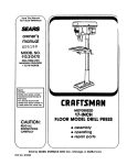
RYOBI OPERATOR'S
MANUAL
10 in. (254 mm) TABLE SAW
Model BTS10
THANK YOU FOR BUYING A RYOBI TABLE SAW.
Your new Table Saw has been engineered and manufacturedto Ryobi'shigh standardsfor dependability,ease of operation,
and operator safety. Properly cared for, it will give you years of rugged, treuble-free performance.
[_k
CAUTION: Carefully read
this entire
through
operator's manual before using your new table saw.
I
Pay close attentionto the Rules for Safe Operation, Warnings, and Cautions. If you use yourtable saw pmpedy and onlyfor
what it is intended, you will enjoy years of safe, reliable service.
Please fill out and return the Warranty RegistrationCard so we can be of future service to you.
Thank you again for buying Ryobi tools.
Table of Contents ...................................................................................................................................................................
2
Rules for Safe Operation ....................................................................................................................................................
3-5
Specific Safety Rules for the BTS1O Table Saw ................................................................................................................
Glossary of Woodworking Terms .......................................................................................................................................
5-6
6-7
Unpacking and Checking Contents .......................................................................................................................................
List of Loose Parts ...........................................................................................................................................................
8
8
Features .................................................................................................................................................................................
9
Assembly .........................................................................................................................................................................
10-11
Tools Needed .................................................................................................................................................................
10
Assembling the Blade Control Handle ...........................................................................................................................
10
Attaching Blade Guard Assembly ..................................................................................................................................
10
Install Miter Gauge ........................................................................................................................................................
11
Installing the Rip Fence Lock Down Handle ..................................................................................................................
11
Installing the Rip Fence .................................................................................................................................................
11
General Information .............................................................................................................................................................
On/Off Switch Key .........................................................................................................................................................
Grounding .....................................................................................................................................................................
Overload Reset Button ..................................................................................................................................................
Speed and Wiring ..........................................................................................................................................................
12
12
12
12
12
Adjustments ...................................................................................................................................................................
13-14
Calibrating and Adjusting Your Saw ...............................................................................................................................
13
Checking/Adjusting Saw Blade and Blade Guard Assembly Alignment ........................................................................ 13
Bevel Adjustments .........................................................................................................................................................
13
Checking 90° and 45 ° Positive Stops ............................................................................................................................
13
ToAdjust the 90 ° Positive Stop ......................................................................................................................................
13
ToAdjust the 45 ° Positive Stop ......................................................................................................................................
14
ToAdjust the Blade Height ............................................................................................................................................
14
ToAdjust the Rip Fence .................................................................................................................................................
14
ToAdjust the Miter Gauge .............................................................................................................................................
14
Operation .......................................................................................................................................................................
15-20
Making Cuts ...................................................................................................................................................................
15
Cutting "13ps....................................................................................................................................................................
16
To Make a Rip Cut .........................................................................................................................................................
16
To Make a Cross Cut ...............................................................................................................................................
16-17
To Make a Miter Cross Cut ............................................................................................................................................
17
To Make a Bevel Cross Cut ...........................................................................................................................................
17
To Make a Bevel Rip Cut ...............................................................................................................................................
18
To Make a Compound Miter Cross Cut ......................................................................................................................... 18
To Make Non-Through Cuts ....................................................................................................................................
!8-19
Push Sticks ....................................................................................................................................................................
19
Safety Considerations ...................................................................................................................................................
20
Maintenance .........................................................................................................................................................................
General Maintenance ....................................................................................................................................................
Specific Table Saw Maintenance ...................................................................................................................................
21
21
21
Troubleshooting ...................................................................................................................................................................
22
Parts Ordering / Service .......................................................................................................................................................
24
Page 2
The purpose of safety symbols is to attract your attention to possible dangers. The safety symbols, and the
explanations
with them, deserve your careful attention and understanding.
The safety warnings do not by
themselves eliminate any danger, The instructions
or warnings they give are not substitutes for proper
accident prevention measures.
SYMBOL
A
A
A
A
NOTE:
MEANING
SAFETY ALERT SYMBOL:
Indicates danger, warning, or caution.May be used in conjunctionwithother symbols or pictogrephs.
DANGER: Failureto obey a safetywarningwill result in serious injuryto yourselforto others.Always
follow the safety precautions to reduce the dsk of fire, electricshock and personal injury.
WARNING: Failuretoobey a safetywarningcanresultin seriousinjurytoyourselfor toothers.Always
followthe safety precautionsto reduce the risk of fire, electricshock and personalinjury.
CAUTION: Failure to obey a safety warning may result in propertydamage or personal injuryto
yourselforto others. Alwaysfollow the safety precautionsto reducethe riskoffire, electricshockand
personalinjury.
Advises you of informationor instructionsvital to the operation or maintenance of the equipment.
IMPORTANT
A WARNING:
Servicing requiresextreme care and knowledgeand should
be performed only by a qualified service technician. For
service we suggestyou retum thetoolto yournearest RYOBI
AUTHORIZED SERVICE CENTER for repair. When
servicing, use only identicalRyobi replacement parts.
WARNING:
Do not attempt to operate this tool until you have read
thoroughly and understand completely all instructions,
safety rules, etc. contained in this manual. Failure to
complycan resultinaccidentsinvolvingfire,electricshock,
or serious personal injury.Save this operator's manual
and review frequentlyfor continuingsafe operation and
instructingothers who may use this tool.
I
Observe all normalsafety precautionsrelated to avoiding I
electrical shock.
I
I®"w'""'"°"I
Keep hands away from blade at all times.
A WARNING:
I
The operation of any table saw can result in foreign objects being thrown into youreyes, which |
can result in severe eye damage. Before beginning power tool operation, always wear safety
goggles or safety glasses with side shields and a full face shield when needed. We recommend
Wide Vision Safety Mask for use over eyeglasses or standard safety glasses with side shields.
I
A
I
Look for this symbol
It means attention!H
to point out important safety
Your safety is involved.
Page 3
precautions.
I
l
READAND
18. Remove adjusting keys and wrenches. Form the habit
UNDERSTAND ALL INSTRUCTIONS
1. Know your power tool. Read and understand the
operator'smanualcarefully.Learn the saw'sapplications
and limitationsas well as the specificpotentialhazards
related to this tool.
2.
Guard against electrical shock by preventing body
contactwith groundedsurfaces such as pipes, radiators,
ranges, refrigerator enclosures.
3.
Ground your saw. Make sure that your saw is properly
polarized with an approved ground connection.
4.
Keep the work area clean. Cluttered work areas and
work benches invite accidents. Do not leave tools or
pieces of wood on the saw while It is in operation.
5.
Avoid dangerous environment. Do not use powertools
near gasolineor otherflammable liquids,in damp or wet
locations, or expose them to rain. Keep the work area
well lit.
of checkingto see that keys and adjustingwrenchesare
removed from tool before turningit on.
19. Avoid accidental starting. Make sure switchis offbefore
plugging saw into power source.
20. Use the proper extension cord. Make sure your
extensioncord is ingood condition.Use onlya cordheavy
enough to carry the current your productwill draw. An
undersizedcordwill causea drop in linevoltageresulting
in loss of power and overheating. A wire gage size
(A.W.G.) ofat least t4 is recommendedforan extension
cord 25 feet or less in length. If in doubt, use the next
heavier gauge. The smaller the gauge number, the
heavier the cord.
21. Keep blades clean, sharp and with sufficient set.
Sharp blades minimizestallingand kickback.
22. Keep hands away from cutting area and the blade,
Do not reach underneath work or in blade cutting path
for any reason. Always turn the power off.
6.
Keep children and visitors away. All visitors should
wear safety glasses and be kept a safe distance from
work area. Do not let visitors contact toot or extension
cord while operating,
7.
Make workshop child-proof with padlocks and master
switches or by removing starter keys.
8.
Do not force the tool Itwill do the job better and more
safely at the rate for which it was designed.
23. Never use this tool in an explosive atmosphere.
Normal sparking of the motor could ignite fumes.
9.
Use the right tool for the job. Do not fo_'cethe tool or
attachment to do a job it was not designed for. Use it
only the way it was intended.
24. Inspect tool cords periodically. If damaged, have
repaired by a qualified service technician at an authorized
Ryobi Service Center. The conductor with insulation
having an outer surface that is green with or without
yellow stripes is the equipment-grounding conductor. If
repair or replacement of the electric cord or plug is
necessary, do not connect the equipment-grounding
conductor to a live terminal. Repair or replace a damaged
or worn cord immediately. Stay constantly aware of cord
location and keep it well away from the moving blade.
10. Dress properly. Do not wear loose clothing, gloves,
neckties,rings, bracelets,or otherjewelry. They can get
caught and drawyou intomovingparts.Non-slipfootwear
is recommended. Also wear protective hair coveringto
contain long hair.
11. Always wear safety glasses with side shields.
Everyday eyeglasses have only impact resistantlenses;
they are not safety glasses.
12. Protect your lungs, Wear a dust mask to keep from
inhalingfine particles.
13. Protect your hearing. Wear headng pmtaction during
extended periodsof operation.
!
_ WARNING:
Blade coastsafter being turned off.
25. Inspect extension
damaged.
cords
periodically
and replace if
26. Keep tool dry, clean, and free from oil and grease.
Always use a clean cloth when cleaning. Never use brake
fluids, gasoline, petroleum-based
products, or any
solvents to clean tool.
14. Do not abuse cord, Never yank cord to disconnectit
from receptacle. Keep cord from heat, oil, and sharp
edges.
27. Stay alert and exercise control. Watch what you are
15. Do not overreach. Keep proper footing and balance at
all times.
28. Check damaged parts. Before further use of the tool,
doing and use common sense. Do not operate tool when
you are tired. Do not rush.
16. Maintain tools with care. Keep toolssharp and clean
for better and safer performance. Follow instructionsfor
lubricating and changing accessories.
17. Disconnect all tools, When not in use, before servicing,
or when changing attachments, blades, bits, cutters, etc.,
all tools should be disconnected from power supply.
check any damaged parts, including guards, for proper
operation and performance. Check alignment of moving
parts, binding of moving parts, breakage of parts, saw
stability, mounting and any other conditions that may
affect its operation. A damaged part must be properly
repaired or replaced by a qualified service technician at
an authorized Ryobi Service Center to avoid risk of
personalinjury.
Page 4
29. Do not use tool if switch does not turn it on and off.
Have defective switches replaced by a qualifiedservice
technicianat an authorized Ryobi Service Center.
30. Guard against kickback. Kickbackcan occurwhen the
blade stalls rapidly, drivingthe work piece back toward
theoperator.It can pullyourhand intothe blade, resulting
in serious personalinjury.Stay out of the blade path and
turn switchoff immediately if blade binds or stalls.
31. Use the rip fence. Always use a fence or straightedge
guide when ripping.
44. Save these instructions. Refer to them frequently and
use to instructother users.If you loansomeone thistool,
loan them these instructionsalso.
[
CAUTION:
When servicing, use only identical Ryobi replacemen
parts. Use of any other parts may create a hazard or cause
product damage.
I
32. Support large work pieces to minimize risk of blade
being pinched and creating a kickback.
33. Before making a cut, be sure all adjustments are
secure.
34. Use only correct blades. Do not use blades with
incorrect size holes. Never use blade washers or bolts
that are defective or incorrect. The maximum blade
capacity of your saw is 10 inches (254 ram).
35. Use recommended accessories. Using improper
accessoriesmay cause dsk of injury.
36. Never stand on tool, Serious injurycould occur if the
tool is tipped or if the blade is unintentionallycontacted.
37. Use the right direction of feed. Feed work intoa blade
or cutter againstthe direction of rotationof the blade or
cutteronly.
38. Never leave tool running unattended. Turn the power
off. Do not leave tool until it comes to a complete stop.
39. Avoid cutting nails. Inspect for and remove all nails
from lumber before cutting.
40. Never touch blade or other moving parts during use.
41. Never start tool when any rotating component is in
contact with the workpiece.
42. Do not operate this tool while under the influence of
drugs, alcohol, or any medication.
Remove all fences and attachments before transporting
saw. Failure to do so can result in an accident causing
possibleserious personalinjury.
Ak WARNING:
I
A WARNING:
Some dust created by power sanding, sawing, grindin
drilling, and otherconstruction activities contains chemicals
known to cause cancer, birth defects or other reproductive
harm. Some examples of these chemicals are:
• lead from lead-based paints,
• crystalline silica from bricks and cement and other
masonry products, and
• arsenic and chromium from chemically-treated
lumber.
Your risk from these exposures varies,depending on how
often you do this type of work. To reduce your exposureto
these chemicals: work in a well ventilated area, and work
with approved safety equipment, such as those dust
masks that are specially designed to filter out microscopic
particles.
43. Ground all tools. If this tool is equipped with a 3-prong
plug, it should be plugged into a 3-hole electrical
receptacle.
Firmly bolt your saw to a workbench or table. The
most comfortable height is approximately 39" (1 m), or
hip height.
Always secure work firmly against rip fence or miter
gauge.
Always use blade guard, riving knife, and antikickback pawls on all "through-sawing" operations.
Through-sawingoperationsare those in whichthe blade
cuts completely through the workpiece as in rippingor
cross-cutting. Keep the blade guard down, the antikickback pawls down, and the riving knife in place over
the blade.
Page 5
Secure work. Use clamps or a vise to hold work when
practical. It'ssafer than usingyour hand and frees both
hands to operate tool.
Always use a push stick for ripping narrow stock. A
pushstickis a device used to pusha workpiecethrough
the blade insteadof usingyour hands. Size and shape
can vary but the push stick must always be narrower
than the workpiece to prevent the push stick from
contactingthe saw blade. When ripping narrow stock,
always use a push stick so your hand does not come
closeto thesaw blade. Use a pushblockor featherboard
for non-throughcuts.
•
Never perform any operation freehand, which means
using onlyyourhands to supportor guide the workpiece.
Always use either the rip fence or the miter guide to
position and guide the work.
•
Never stand or have any part of your body in line
with the path of the saw blade.
•
Never reach behind, over, or within three inches of the
blade with either hand for any reason.
•
Move the rip fence out of the way when cross-cutting.
•
Never use the rip fence as a cut-off gauge when crosscutting.
•
Never attempt to free a stalled saw blade without first
turning the saw off and disconnecting the saw from the
power source.
•
Use a support for the sides and back of the saw table
when sawing wide or long workpieces.
To prevent
tipping, use a sturdy "outrigger"
support if a table
extension is more than 24 inches long and is attached to
the saw,
•
•
Avoid kickbacks (work thrown back toward you) by:
Keeping the blade sharp.
Keeping rip fence parallelto the saw blade.
Keeping riving knife, anti-kickback pawls, and blade
guard in place and operating.
Not releasing the work before it is pushed all the way
pastthe saw blade using a push stick.
Not rippingwork that is twisted or warped or does not
have a straight edge to guide along the fence.
•
Check with a qualified electrician if grounding
instructionsare not completelyunderstoodor if in doubt
as to whetherthe tool is properlygrounded.
•
Use only correct electrical devices: 3-wire extension
cords that have 3-prong grounding plugs and 3-pole
receptaclesthat accept the toors plug.
•
Do not modify the plug provided. If it will not fit the
outlet, have the proper outlet installed by a qualified
electrician.
•
Use only recommended
accessories
listed in this
manual. Blades must be 10" (254 mm) in diameter, rated
for at least 4,800 rpm or higher, with 5/8" (16 mm) arbor
holes. Use of accessories that are not listed may cause
the risk of personal injury. Instructions for the safe use of
accessories are included with the accessory.
•
Double check all setups. Make sure blade is tight and
not making contact with saw or workpiece before
connecting to power supply.
•
Make sure the work area has ample lighting to see
the work and that no obstructions will interfere with safe
operation before performing any work using this tool,
•
Always turn off saw before disconnecting it, to avoid
accidental starting when reconnecting to power supply.
Never leave the table saw unattended while connected
to a power source.
•
Save these instructions.
Refer to them frequently and
use to instruct other users. If you loan someone this tool,
loan them these instructions also.
Avoid awkward operations and hand positions where
a sudden slip could cause your hand to move intothe
blade.
Anti-Kickback Pawls
Device which, when properly installed and maintained, is
designed to stop the workpiece from being kicked back
toward the front of the saw during a dppingoperation.
Arbor
The shaft on which a blade or cuttingtool is mounted.
Bevel Cut
A cutting operation made with an angled blade.
Dado
A non-through cut which produces a square sided notch or
trough in the workpiece.
Featherboard
A device used to help controlthe workpiece by guiding it
securely against the table or fence during any rip cut
operation.
Compound Miter Cut
A single cutmade with botha miterangle and a bevel angle.
Cross Cut
A cut or shaping operation made across the grain of the
workpiece.
Freehand
Performinga cut withoutusing a fence, miter gauge, fixture,
hold down clamp, or other proper device to keep the
workpieca from twisting during the cut.
Gullets
The valleys or notchesbetween the teeth in a saw blade.
Cut-off Stock
Gum
The unused material that remains after a cuffingoperation,
A sticky, sap-based residue from wood products.
Page 6
Heel
Misalignment
oftheblade,
Kerf
Rip Fence
Adjustable guide used in ripping cuts to keep the workpiece
parallelto the saw blade.
The amount of material removed by the blade in a throughcut, or the slot produced by the blade in non-through or partial
cut.
Riving Knife
Also known as a separatoror spreader.A metal piece slightly
thinnerthan the saw blade which helps keep the kerf open
during cuttingand preventskickbacks.
Kickback
An uncontrolledgrabbing or throwing of the workpiece back
toward the front of the saw. Associated with the workpiece
closing the kerf and pinching the blade or otherwise placing
tension on the blade.
Leading End
The end of the workpiece which, during a rip type operation,
is pushed into the cutting tool first.
Miter Cut
A cutting operation made with the wood at any angle other
than 90 ° to the blade.
Molding
A cut which produces a specialshape in the workpiece,used
for joiningor decoration.
Non-Through Cut
Any cutting operation where the blade does not extend
completelythrough the thicknessof the workpiece.
Push Block
A device used tofeed the workpiecethrough the saw, except
duringnarrow riptype operationswhere a push stickshould
be used. It also helps keep the operator'shands well away
from the blade.
Push Stick
A device used to feed the workpiecethrough the saw to help
keep the operator'shands well away from the blade.
Rabbet
A notch in the edge of the workpiece.
Resin
A sticky,sap-based substancethat has hardened.
Rip Cut
A cutting or shapingoperationmade alongthe length or grain
of the workpiece.
RPM
Revolutionsper Minute. The number of turns completed by
a spinningobject in one minute. Used to measure the speed
of the blade.
Saw Blade Path
The area over, under, behind, or in front of the blade. As it
appliestothe workpiece,that area whichwillbe, or has been,
cut by the blade.
Set
The distance that the tip of the saw blade tooth is bent (or
set) outward from the face of the blade.
Throat Plate
That part of the table surface through which the blade
protrudes.Removal of the throat plate allows access to the
blade arbor.
Throw-Back
Throwing of a workpiece in a manner similar to a kickback.
Usually associatedwith a cause otherthan the kerf closing,
such as a workpiece being droppedonto the blade or being
placed inadvertentlyin contact with the blade.
Through Sawing
Any cutting operation where the blade extends completely
through the thickness of the workpiece.
Trailing End
The end of the workpiece last cut by the blade in a ripping
operation.
Workpiece
The piece of wood on which the cutting operation is being
performed.
Page 7
Your Model BTS10 Table Saw is shipped complete in one
carton and includes rip fence, miter gauge, blade guard,
accessory storage brackets, wrenches, Operator'sManual,
and warranty information.
When you get your new table saw home, unpack the box to
make sure all information and accessories are included.
Separate all loose parts and compare with the illustration
below to make sure all loose items are accounted for. Do not
discard any packing material until you are sure you have
everything or have checked all packaging for any missing
parts.
If any parts are missing or damaged, contact 1-800-525-2579.
WARNING:
To avoid risk of serious personal injury, do not attemptto
assemble the table saw, plug in the power cord, or turn
the power switch on until all damaged or missing parts
are obtained and properly installed.
4
1
9
10
2
14
is
i6
19
Fig. 1
List of Loose
Parts
Key # Description
1
2
3
4
5
6
7
8
9
10
Quantity
Key # Description
Rip Fence ........................................................... 1
Rip Fence Lock Down Handle ............................ 1
M4 x 15 mm Tapping Screw ...............................
Blade Guard/Riving Knife Assembly ...................
1/4-20 x 2-1/4" Socket Head Bolt .......................
1/4" External Tooth Lock Washers ......................
114"Internal Tooth Lock washer .........................
1/4" Flat Washer .................................................
1
1
1
4
1
2
Blade Guard Mounting Bracket .......................... 1
Blade Guard Support Bracket ............................. 1
Page 8
Quantity
11
1/4-20 x 1/2" Hex Head Bolt ............................... 2
12
13
14
15
16
M6 Wing Nut .......................................................
M6 x 19 mm Carriage Bolt..................................
Blade Control Handle .........................................
1/4-20 x 2-7/16" Shoulder Bolt ...........................
1/4-20 Lock Nut ..................................................
1
1
1
1
1
17
18
19
20
Miter Gauge ........................................................
Wrenches ...........................................................
1/4" Flat Washer .................................................
Operator's Manual (Not Shown) .........................
1
2
1
1
Know Your Table Saw
•
Blade height control handle to set depth of cut.
Your saw is designed to perform as a versatile, accurate,
precision wood cutting tool that is easy to operate. It is
equipped with the followingfeatures for convenience, ease
of use, and high quality performance:
•
Combination saw blade.
•
•
Rack and pinion bevel control.
Overload reset button.
•
On/off switch key.
•
Bevel indicator to set the exact angle of the blade, with
locking lever.
•
Adjustable miter gauge.
•
Adjustable rip fence with scale indicator.
•
Riving knife and blade guard with anti-kickback pawls.
•
Front and rear guide rails with an easy to read scale on
front rail.
WARNING:
Before attempting to use your new Ryobi table saw,
familiarize yourself with all the safety requirements listed
in this Operator's Manual and the operating features
shown in Figure 2.
i
BLADEGUARD
MITERGAUGE
LOCKKNOB
RIVINGKNIFE
ANTI-KICKBACK
PAWLS
10"(254mm)BLADE
MITERSCALE
THROATPLATE
MITERGAUGE
CHANNEL
ON/OFFSWITCHWITH KEY
BLADE
CONTROLHANDLE
RIPFENCE
BEVEL
LOCKLEVER
ACCESSORY
STORAGE
BRACKETS
(NOTSHOWN)
BEVELSCALE
RIPFENCELOCK
DOWNHANDLE
FRONTRAIL
RIPFENCE
SCALE
Fig. 2
Page 9
Do not connect to power supply until assembly is
complete. Failure to comply could result in accidental
_ WARNING:
starting and possibleserious personal injury.
I
TOOLS NEEDED
Fig. 4
i
Assemble the internal tooth lock washer, flat washer, and
external tooth lock washer onto the 1/4-20 x 2-1/4" socket
head bolt. Then feed the assembled bolt through the hole in
the mounting bracket and into the exposed end of the
threaded rod at the back of the saw as show in Figure 5.
Securely tighten with hex wrench provided.
NOTE: The exposed end of the threaded rod on the back of
the saw inserts into the recessed end of the mounting bracket.
ASSEMBLING THE BLADE CONTROL HANDLE
Feed the 1/4-20 x 2-7/16" shoulder bolt through the front of
the handle so that the screw head is recessed in the handle.
Place the M6 wing nut in the nut pocket in the rear of the
control wheel, behind the pre-drilled hole. Place your finger
over the nut to hold it in place.
Insert the screw through the hole in the front of the control
wheel. Holding the nut and screw in place, tighten with a
Phillips screwdriver.
ATTACHING
WARNING:
BLADE GUARD ASSEMBLY
Loosen bevel control by turning bevel lock lever all the way
to the left. If it needs to be further loosened, pull spring-loaded
bevel lock lever out and rotate it back to the right. Release
bevel lock lever and allow it to seat in its original position.
Turn it to the left again until loose.
Push the handle on the control wheel in toward the saw and
rotate clockwise until the blade is set to 90 ° as indicated on
the bevel indicator.
Confirm blade guard assembly is properly aligned and all
mounting hardware is attached and securely tightened
before each use of the saw. Failure to comply can result
in serious personal injury.
Position the blade guard on the supportbracket so that the
top circular tab fits in the upper hole in the blade guard
assembly and the lower tab is in the slot. See Figure 6.
Tighten bevel controlby turning bevel lock lever to the right.
If it needs to be tightened more, pull the spring-loaded bevel
lock lever out and rotate it to the left. Then release bevel
lock lever and allow it to return to its original position. Rotate
to the right again. Repeat this process until bevel lock lever
is securely tightened.
Fastenthe support bracket to the mounting bracket as shown
in Figure 4 using the two 1/2" hex head bolts and two 1/4"
external tooth lock washers. Do not tighten bolts.
Fig. €
Page 10
Attach blade guard assembly to support bracket with
M6 x 19 mm carriage bolt. Secure with a 1/4" flat washer,
external tooth lock washer and wing nut.
NOTE: Before tightening wing nut, make sure there is at least
1/8" (3 mm) between the end of the table and blade guard
assembly. Also check to make sure that the two circular tabs
are still engaged inside the upper hole and slotted opening.
Raise the saw blade by turning the control wheel handle
counterclockwise.
Raise the transparent blade guard, then use a straight edge
to make sure that the blade guard assembly is aligned with
the saw blade.
If the blade guard assembly is not aligned with the blade,
loosen the 1/2" hex head bolts and/or the 2-1/4" socket head
bolt and reposition the blade guard assembly so that it is
aligned with the blade. Once aligned, securely tighten all bolts.
Fig. ?
i
INSTALLING THE RIP FENCE
Failure to confirm blade guard assembly is properly
aligned with the blade could cause the workpiece to jam
while sawing, causing kickback and injury,
_
WARNING:
INSTALL
MITER
I
GAUGE
To install the pre-assembled
miter gauge, simply slide the
long end of the miter gauge into the miter gauge channel as
shown in Figure 7.
INSTALLING
THE RIP FENCE
LOCK
DOWN
HANDLE
Locate the lock down handle and an M4 x 15 mm tapping
screw.
The rip fence attaches to the rear and front rails by two flanges
on either end of the fence, When the lock down handle is in
the Up position (parallel to the fence), the flanges are relaxed,
allowing you to reposition the rip fence. When the lock down
handle is in the Down position (perpendicular to the fence),
the flanges are drawn together and the rail is held in place.
To install the rip fence, place the end furthest from the handle
so that the flange is over the rear edge of the table: Then
lower the end closest to the lock down handle over the front
rail.
NOTE: For accuratealignment,make surethatthe frontblock
is flush against the front rail.
Push the lock down handle downto fix the railin place.
Slide the handle over the exposed end of the rip fence. Make
sure the handle is inserted as far as it can go. The hole in the
metal rip fence should line up with the recessed hole in the
handle. Secure handle using the M4 x 15 mm tapping screw.
Page 11
Check with a qualified electrician or service personnel if the
grounding instructions are not completely understood, or if
in doubt as to whether the tool is propedy grounded.
WARNING:
Yourtable saw has a precision built electric motor. It should
only be connected to a power supply that is 120 volts,
60 Hz, AC only (normal household current). Do not operate
this tool on direct current (DC). A substantial voltage drop
will cause a loss of power and the motor will overheat. If
your tool does not operate when plugged into an outlet,
double check the power supply.
ON/OFF
SWITCH
Repair or replace a damaged or worn cord immediately.
This tool is intended for use on a circuit that has an outlet
like the one shown in Figure 9. It also has a grounding pin
like the one shown.
KEY
Your Ryobi table saw is equipped with an on/off switch key
that, if removed, prevents the saw from being turned on. The
key must be in place to turn the saw on. If the key is removed
during operation, the saw may be turned off but may not be
turned on again until the key is replaced. See Figure 8.
GRO ,"=NG \
COVEROFGROUNDED
OUTLETBOX
Fig. c
#
OVERLOAD
Fig. 8
GROUNDING
In the event of a malfunction or breakdown, grounding
provides a path of least resistance for electric current to
reduce the risk of electric shock. This tool is equipped with
an electric cord having an equipment-grounding conductor
and a grounding plug. The plug must be plugged into a
matching outlet that is properly installed and grounded in
accordance with all local codes and ordinances.
Do not modify the plug provided. If it will not fit the outlet,
have the proper outlet installed by a qualified electrician.
Improper connectionof the equipment-groundingconductor
can result in electricalshock.The conductorhavingan outer
surface that is green with or without yellow stripes is the
equipment-groundingconductor.If repair or replacement of
the electric cord or plug is necessary, do not connect the
equipmentconductorto a live terminal.
_ WARNING:
If an extension
cord
is used,
I
make
sure
Your Ryobi table saw features an overload reset button. In
the event that your saw turns off during operation,turn the
saw off and allow the motorto cool down for approximately
3 minutes. Push the reset buttonand attemptto turnthe saw
on again. If the saw does not turnon, turn the switchoff and
check all cordsfor properconnectionand retry.If it stilldoes
not turn on, contactyour authorizedRyobi Service Center. If
it turns on and then cutsoff whileyou are working,you may
be trying to feed the workpiece too quickly or may be
operating with a dull blade or may be tryingto operate on a
circuitprovidinginsufficientvoltage.
SPEED
AND WIRING
The no-loadspeed of your saw is approximately 4,800 rpm.
This speed is not constantand decreases under a load or
with lower voltage. A line intended only for lights cannot
properlycarrya powertool motor.Wire that is heavyenough
for a shortdistancewill be too lightfor a greater distance.A
line that can support one power tool may not be able to
supporttwo or three.
it is a grounded/I
3-prongplug and is adequateto prevent excessive voltage I
loss. See ExtensionCord Caution on back page.
RESET BUTTON
J
Page 12
CALIBRATING
AND ADJUSTING
YOUR
SAW
BEVEL ADJUSTMENTS
WARNING:
Before performing any adjustmentsor calibrations, make
sure the table saw is unplugged from the power supply
and the switch is in the "OFF" position.Failure to heed
this warning can resultin serious personal injury.
Before operating your saw, check for proper alignment of
the blade and riving knife. You should also check that the
90 ° and 45 ° positive stops are accurate. These should be
done prior to each use.
CHECKING/ADJUSTING
BLADE
GUARD
SAW
ASSEMBLY
BLADE
AND
Your Ryobi Table Saw has a rack and pinion bevel control
that allowsyou to make angled cuts from 90 ° to 45 °.
NOTE: A 90 ° cut has a 0 ° bevel and a 45 ° cut has a 45 °
bevel.
To change the bevel angle follow these steps.
1. Disconnectthe saw from the power supply.
2.
Loosen bevel control by turning bevel lock lever all the
way to the left. If it needs to be further loosened, pull
spring-loaded bevel lock lever out and rotate it back to
the right. Release bevel lock lever and allow it to seat in
its original position. Turn it to the left again until loose.
3.
Adjust the bevel angle by pushing the wheel in toward
the saw then turning it. Turning the wheel counterclockwise increases the angle of the blade, bdnging it
closer to 45 °. Turning it clockwise decreases the angle,
bringing the blade closer to 90 °.
4.
Tighten bevel control by turning bevel lock lever to the
dght. If it needs to be tightened more, pull the spdngloaded bevel lock lever out and rotate it to the left. Then
release bevel lock lever and allow itto return to its original
position. Rotate to the right again. Repeat this process
until bevel lock lever is securely tightened.
ALIGNMENT
To check the alignment of the saw blade and blade guard
assembly, raise the blade guard. Place a straight edge flush
against the face of the saw blade. The straight edge should
line up flush with the blade guard assembly. Lower the blade
guard to its original position.
If the blade guard assembly and blade are not in alignment,
adjust the blade guard assembly by doing the following:
1. Raise the blade guard.
2.
To adjust the horizontalalignment, loosen the two 1/2"
hex head bolts holding the mounting bracket to the
support bracket. See Figure 10. Reposition the blade
guard assembly so that the blade guard assembly lines
up with the saw blade. Securely tighten bolts.
CHECKING
90 ° AND 45 ° POSITIVE
STOPS
To check the 90 ° positive stop, use a framing square. First,
make sure the bevel indicator is as far to the left as possible.
This will engage the 90 ° positive stop. Next, place the square
with one side flush with the table surface. The other side
should line up flush with the blade.
To check the 45 ° positive stop, use the angled corner of the
combination square. Engage the bevel control and tilt the
blade all the way to the dght to engage the 45 ° positivestop.
Place the square on the table surfacewith the angled corner
against the blade. The blade and table shouldbothbe flush
with the square.
If the positivestops need adjusting,proceed as follows.
TO ADJUST THE 90° POSITIVE STOP
Fig. 10
3.
4.
To adjustthe verticalalignment,loosen the 2-1/4" socket
head bolt holding the mounting bracket to the back of
the saw. Use a framing square to make sure the blade
guard assembly is perpendicular to the table surface.
Securely tighten bolt.
Return the blade guard to the lowered position.
WARNING:
If the blade guard/riving knife is out of alignment with the
saw blade, adjust the alignment of the blade guard/riving
knife assembly and securely tighten all mounting
hardware. Do not attempt to adjust the alignment of the
saw blade. Failure to heed this warning can result in
serious personal injury.
Make sure the saw is unplugged from the power source.
Raise the blade to the maximum height byturningthe blade
controlwheel counterclockwise.Loosenthe bevel controlby
turningthe bevel lock lever to the left.
Next, push the blade control wheel in toward the saw and
rotateclockwiseuntilitstops.Use theframingsquaretocheck
the positionof the blade.
If the blade angle is less than 90 °, turn the 90 ° Positive
StopAdjustmentScrewcounterclockwiseone tum. Pushthe
blade control wheel in and rotate counterclockwiseuntil it
stops. Recheck the blade position. Continue this process
until the blade is at 90°. Tightenthe bevel controllever.
If the blade angle is greater than 90 °, use the framing
square to positionthe blade to 90 °. Turn the 90° Positive
Stop Adjustment Screw clockwiseuntil it stops.Tightenthe
bevel controllever.
Page 13
For through-cuts, place the workpiece to be cut flush
against the blade. Set the blade so that the tips of the
uppermost tooth are about an 1/8" (3 mm) higher than
the workpiece and the valley between the teeth (gullet)
is lower than the workpiece as in Figure 13.
3,
,L
APPROXIMATEU
Fig. 15
Reset the Bevel Indicator to 90 ° by loosening the screw
holding the indicator. Line up the red line on the indicator
with the 0° mark on the bevel scale.
TO ADJUST
THE 45 ° POSITIVE
4.
For non-through cuts, use a ruler or other graduated
straight-edge to measure from the table surface to the
tip of the uppermost tooth on the blade.
TO ADJUST THE RIP FENCE
STOP
Make sure the saw is unplugged from the power source.
Raise the blade to the maximum height by turning the blade
control wheel counterclockwise.
Turn the bevel lock lever to
the left to loosen the bevel.
Next, push the blade control wheel in and rotate
counterclockwise until it stops. Check the blade position using
the angled corner of a combination square or triangle.
To reposition the rip fence, lift the lock down handle to the
Up position(parallel to the fence). Use the indicatoron the
fence to slidethe fence to the desired position.Make sure
the front bar on the rip fence is flush against the front rail.
Then move the lock down handle to the Down position
(perpendicularto the fence).
TO ADJUST TENSION ON THE RIP FENCE
To avoid risk of kickback and to ensure accuracy, the rip
fence must be securely attached to the front rail and rear
edge. If there is lateral play in the fence, tighten the
adjustment nut at the back of the fence. If the rip fence lock
down lever is too tight, loosen the adjustment nut.
The rip fence must be positioned parallel to the miter
gauge channel to prevent risk of kickback.
WARNING:
Fig. 12
If the blade angle is greater than 45 ° , turn the 45 ° Positive
Stop Adjustment Screw counterclockwise 1 turn and rotate
the bevel control wheel counterclockwise until it stops.
Recheck the blade position. Continue this process until the
blade is at 45 °. Tighten the bevel control lever.
If the blade angle is less than 45 ° , use the combination
square or triangle to position the blade at 45 °, Turn the 45 °
Positive Stop Adjustment
Screw clockwise until it stops.
Tighten the bevel control lever.
Reset the Bevel Indicator to 45° by loosening the screw
holding the indicator. Line up the red line on the indicator
with the 45 ° mark on the bevel scale.
TO ADJUST
THE BLADE
HEIGHT
1. Disconnectsaw from power supply.
2. Turn blade control wheel. Turningit clockwise lowers the
blade. Turningit counterclockwiseraises it.
J
To ensure proper alignment,use a framing squareto measure
the distance from the front end of the rip fence to either of
the miter gauge channels. Then measure from the rear end
of the fence to the same miter gauge channel. If the two
measurementsare not the same, repositionthe rear end of
the fence and measure again.
TO ADJUST THE MITER GAUGE
To adjust the miter gauge, simply loosen the lock knob and
rotate the miter gauge to the desired position. Then tighten
the lock knob.
NOTE: There are two miter gauge channels,one on either
side of the blade. When making a 90° cross-cut, you can
use either miter gauge channel. When making a beveled
cross cut (the blade tilted in relation to the table) the miter
gauge shouldbe located in the slot on the right so that the
blade is tilted away from the miter gauge and your hands.
Page 14
MAKING CUTS
There are seven basic types of cuts:
Bevel Rip Cut
Cut made along the grain with the blade tilted.
Straight Cross Cut
Cut made across the grain.
Fig. 1£
Fig. 1_
Miter Cross Cut
Cut made with the workpiece at an angle (other than 90 °)
relative to the blade,
Compound Miter Cross Cut
Cut made with an angled blade on wood that is angled to the
blade.
[
Non-through Cut
A cut in whichthe blade does not cutthrough the entirethickness of the workpiece.
Straight Rip Cut
Cut made with the grain.
Fig. 17
Bevel Cross Cut
Cut made with the blade tilted relative to the table surface
across the grain.
Page 15
This section deals with the proper procedures for making
these seven basic cuts.
CUTTING
3.
TIPS
The kerf (the cut made by the blade in the wood) will be
wider than the blade to prevent overheating or binding.
Make allowances for the kerr when measuring wood.
Make sure the kerf is made on the scrap side of the
measuring line.
Cut the wood with the finish side up.
Knock out any loose knots with a hammer before making
the cut.
Always provide proper support for the wood as it comes
out of the saw.
TO MAKE A RIP CUT
4. Make sure that all loose items have been removed from
the table surface and that the workpiece is not in contact
with the blade.
5. Turn the On/Oft switch to the On position.
6. Position the workpiece flat on the table with the edge
flush against the rip fence. Let the blade build up to full
speed before feeding the workpiece into the blade.
7. Using a push stick and/or push blocks, slowly feed the
workpiece toward the blade. Stand slightly to the side of
the wood as it contacts the blade to reduce the chance
of injury should kickback occur.
8,
It is recommended that you make a test cut on scrap wood
first.
& WARNING:
9.
Make sure the blade guard assembly is securely installed
and working properly to avoid sedous personal injury.
,
If ripping a piece larger than 36" long, place a support
the same height as the table surface behind the saw for
the cut work.
Once the blade has made contact with the workpiece,
use the hand closest to the rip fence to guide it. Make
sure the edge of the workpiece remains in solid contact
with both the rip fence and the surface of the table. If
ripping a piece narrower than 4", use a push stick to
move the piece through the cut and past the blade.
Continue to feed the workpiece into the blade until the
cut has been completed.
10. Grasp the workpiece from the lead end (the end that
was fed into the blade first) and carefully remove it from
the table.
11. Turn the On/Off Switch to the Off position.
12. After the blade has stopped completely, remove the cutoff stock.
A WARNING:
GUIDINGHAND
PUSHINGHAND
PROPERFEEDINGPROCEDURE
FORRIPCUTS
Fig. 21
i
To avoidseriouspersonal injury, never push a small piece
of wood intothe blade with yourhand, always use a push
stick. The use of push blocks, push sticks, and
featherboards are mandatory when making non-through
cuts.
TO MAKE A CROSS-CUT
It is recommendedthat you make a test cut on scrap wood
first.
Make surethe bladeguard assembly issecurelyinstalled
A WARNING:
and workingproperlyto avoid seriouspersonal injury.
I
1. Remove the rip fence by liftingthe lock downhandle.
2. Loosenthe lock knob on the miter gauge, set the miter
gauge to 90 ° and tighten the lock knob.
1. Removed the miter gauge by sliding it out of the channel.
2. Position the rip fence the desired distance from the blade,
remembering to allow for the kerf, and lock down the
handle.
3. Make sure that all loose items have been removedfrom
the table surface and that the workpieceis not in contact
with the blade.
4. Turn the On/Oft Switch to the On position.
Page 16
5. Position the workpiece flat on the table with the edge
flush against the miter gauge. Let the blade build up to
full speed before feeding the workpiece into the blade.
workpiece toward the blade. Stand slightly to the side of
the wood as it contacts the blade to reduce the chance
of injury should kickback occur.
6. Use two hands to slowly advance the workpiece and the
miter gauge toward the blade. Use the hand furthest from
the blade to keep the workpiece flush against the miter
gauge. Use the other hand to push the miter gauge and
workpiece toward the blade. Stand slightly to the side of
the wood as it contacts the blade to reduce the chance
of injury should kickback occur.
7. Continue to feed the workpiece into the blade until the
cut has been completed.
7. Continue to feed the workpiece into the blade until the
cut has been completed.
8. Once the cut is complete, pull the workpiece away from
the blade and back toward you.
9. Turn the On/Off Switch to the Off position.
8. Once the cut is complete, pull the workpiece away from
the blade and back toward you.
9. Turn the On/Off Switch to the Off position.
10. After the blade has stopped completely, remove the cutoff stock.
TO MAKE A BEVEL CROSS CUT
It is recommended that you place the piece to be saved on
the left side of the blade and that you make a test cut on
scrap wood first.
10. After the blade has stopped completely, remove the cutoff stock.
TO MAKE A MITER CROSS CUT
Make sure the blade guard assembly issecurelyinstalledI
It is recommendedthat you make a test cat on scrap wood
first.
IA
WARNING:
and workingproperlyto avoid serious personalinjury.
J
1. Remove the rip fence by lifting the lock down handle.
page
Make sure the blade guardassembly is securelyinstalled
I
and working properlyto avoid serious personal injury.
_
WARNING:
13.
3.
the the
bladebevel
to theangle
correctto depth.
See page
14. See
2. Set
Adjust
the desired
setting.
4. Loosen the lock knob on the miter gauge, set the miter
gauge to 90 ° and tighten the lock knob.
5. Make sure that all loose items have been removed from
the table surface and that the workpiece is not in contact
with the blade.
6. Turn the On/Off Switch to the On position.
7. Position the workpiece flat on the table with the edge
flush against the miter gauge. Let the blade build up to
full speed before feeding the workpiece into the blade.
8. Use two hands to slowly advance the workpiece and the
miter gauge toward the blade. Use the hand furthest from
the blade to keep the workpiece flush against the miter
gauge. Use the other hand to push the miter gauge and
workpiece toward the blade. Stand slightly to the side of
the wood as it contacts the blade to reduce the chance
of injury should kickback occur.
Fig. 23
1. Remove the dp fence by lifting the lock down handle.
2. Loosen the lock knob on the miter gauge, set the miter
gauge to the desired angle and tighten the lock knob.
3. Make sure that all looseitems have been removed from
the table surface and that the workpiece is not in contact
with the blade.
10. Once the cut is complete, pull the workpiece away from
the blade and back toward you.
4. Turn the On/Off Switch to the On position.
11. Turn the On/Off Switch to the Off position.
5. Position the workpiece flat on the table with the edge
flush against the miter gauge. Let the blade build up to
full speed before feeding the workpiece into the blade.
12. After the blade has stopped completely, remove the cutoff stock.
9. Continue to feed the workpiece into the blade until the
cut has been completed.
6. Use two hands to slowly advance the workpiece and the
miter gauge toward the blade. Use the hand furthest from
the blade to keep the workpiece flush against the miter
gauge. Use the other hand to push the miter gauge and
Page17
TO MAKE A BEVEL
RIP CUT
TO MAKE A COMPOUND
It is recommended that you place the piece to be saved on
the right side of the blade and that you make a test cut on
scrap wood first.
rip fence must be on the right side of the blade to
_The
WARNING:
]
avoid trapping the wood and causing kickback.
MITER
CROSS
CUT
It is recommended that you place the piece to be saved on
the left side of the blade and that you make a test cut on
scrap wood first.
l, WARNING:
Make sure the blade guard assemblyis securelyinstalled
and workingproperlyto avoid serious personalinjury.
I
1. Remove the rip fence by lifting the lock down handle.
Make sure the blade guard assembly issecurely installed
and workingproperlyto avoid serious personalinjury.
WARNING:
2. Adjust the bevel angle to the desired setting. See
page 13.
I
1. Remove the miter gauge by sliding it out of the channel.
2. Position the rip fence the desired distance from the right
side of the blade and lock down the handle.
3. Adjust the bevel angle to the desired setting. See
page l&
4. Set the blade to the correct depth. See page 14.
5. If ripping a piece larger than 36" long, place a support
the same height as the table surface behind the saw for
the cut work.
6. Make sure that all loose items have been removed from
the table surface and that the workpiece is not in contact
with the blade.
7. Turn the On/Off switch to the On position.
8. Position the workpieca flat on the table with the edge
flush against the rip fence. Let the blade build up to full
speed before feeding the workpiece intothe blade.
9. Using a push stick and/or push blocks, slowly feed the
workpiece toward the blade. Stand slightly to the side of
the wood as it contacts the blade to reduce the chance
of injury should kickback occur.
10. Once the blade has made contact with the workpieca,
use the hand closest to the rip fence to guide it. Make
sure the edge of the workpieca remains in solid contact
with both the rip fence and the surface of the table. If
ripping a piece narrower than 4", use a push stick to
move the piece through the cut and past the blade.
11. Continue to feed the workpiece into the blade until the
cut has been completed.
12. Grasp the workpieca from the lead end (the end that
was fed into the blade first) and carefully remove it from
the table.
13. Turn the On/Off Switch to the Off position.
14. After the blade has stopped completely, remove the cutoff stock.
3. Set the blade to the correct depth. See page 14.
4. Loosen the lock knob on the miter gauge, set the miter
gauge to the desired angle and tighten lock knob.
5. Make sure that all loose items have been removed from
the table surface and that the workpiece is not in contact
with the blade.
6. Turn the On/Off Switch to the On position.
7. Position the workpieca fiat on the table with the edge
flush against the miter gauge. Let the blade build up to
full speed before feeding the workpiece into the blade.
8. Use two hands to slowly advance the workpiece and the
miter gauge toward the blade. Use the hand furthest from
the blade to keep the workpieca flush against the miter
gauge. Use the other hand to push the miter gauge and
workpieca toward the blade. Stand slightly to the side of
the wood as it contacts the blade to reduce the chance
of injury should kickback occur.
9. Continue to feed the workpiece into the blade until the
cut has been completed.
10. Once the cut is complete, pull the workpiece away from
the blade and back toward you.
11. Turn the On/Off Switch to the Off position.
12. After the blade has stopped completely, remove the cutoff stock.
TO MAKE NON-THROUGH
CUTS
Non-threugh cuts can be made with the grain (ripping) or
across the grain (cross cut). Non-throughcutsare essential
in cuttinggrooves,rabbets, and dadoes. This isthe onlytype
of cut made with the blade guard assembly removed. You
must make sure the entire blade guard assembly is reinstalled properlyupon completionof this type of cut.
In additionto this section, make sure to read the sectionon
the specifictype of non-throughcutbeingmade. Forexample,
if your non-threughcut is a cress cut, read and understand
the sectionon cross cuts thoroughlybefore proceeding.
IA
WARNING:
Unplug the saw to avoid serious personal injury.
Page 18
I
|
!
1. Remove
thewing nut and carriage
bolt holding the blade
guard assembly to the blade guard support bracket. See
Figure 24. Remove the blade guard assembly.
2.
Lower the blade to the correct height by turning the blade
control handle counterclockwise.
3.
Always use push blocks, push sticks and featherboards
when making non-through cuts to avoid the risk of serious
personal injury. See Figure 25.
PUSH STICKS
A push stick is a device used to safely push a workpiece
through the blade instead of using your hands. Push sticks
in various sizes and shapes can be made from scrap wood.
The stick must always be narrower than the workpiece. If it
is too wide, it may jam on the rip fence or blade. When ripping
narrow stock, always use a push stick so your hand does
not come close to the saw blade.
NOTE: Push blocks and featherboards should always be
used when making non-through cuts.
WARNING:
Carefully check all set ups and rotate the blade one full
revolutionto assure properclearance before connecting
saw to power source. Failure to comply can result in
serious personal injury.
A simple push stick design is shown in Figure 25. Remember
that the push stick must always be narrower than your
workpiece. You may want to make several push sticks of
varying widths.
WING NUT
Fig. 2_
Fig. 2_=
WARNING:
Never feed wood through with your hands when making
non-throughcuts such as rabbetsor dadoes.Always use
push sticksand pushblocks. Failureto head this warning
can result in serious personalinjury.
4.
When the cut is complete, unplugthe saw and raise the
blade.
5.
Reinstallthe blade guard assembly,attachingthe blade
guardassemblyto the supportbracket usingthe carriage
bolt and wing nut. Make sure the circular tabs on the
supportbracket are alignedwiththe hole and sloton the
blade guard assembly.Tighten the wing nut. Securely
tighten all mountinghardware.
6.
Check rivingknife alignmentto blade face and adjust if
necessary. See page 13.
WARNING:
Confirm blade guard assembly is properly alignedand all
mounting hardware is attached and securely tightened
before each use of the saw. Failure to comply can result
in serious personal injury.
Page19
SAFETY CONSIDERATIONS
TO AVOID KICKBACK
AVOIDING
1. Always use the correct blade depth setting. The top of
the blade teeth should clear the workpiece by 1/8" to
1/4".
KICKBACK
Kickback can occur when the blade stalls or binds, kicking
the workpieca back toward the front of the saw with great
force and speed. Kickback can cause serious injury.
Precautions must be taken to avoid the risk of kickback.
2.
Inspectthe workpieca for knots or nails before beginning
a cut. Knock out any loose knots with a hammer. Never
saw into a loose knot or nail.
3.
Make straight cuts. Always use the rip fence when rip
cutting. This helps prevent twisting the wood in the cut.
4.
Always use clean, sharp, properly-set blades. Never
make a cut with a dull blade.
5.
To avoid pinching the blade, support the workplace
properly before beginning a cut.
The followingcan cause kickback and should be avoided:
making a cut with incorrectblade depth.
attemptingto saw throughknotsor nailsinthe workpieca.
twistingthe wood while making a cut.
failingto propedy positionthe rivingknife.
making a cut with a dull, gummed-up, or improperly set
blade.
failing to support large workpieces.
8. When making a cut, use steady, even pressure. Never
force a cut.
forcing the workpiece through the saw blade.
7.
cutting warped or wet lumber.
8.
Do not cut wet or warped lumber.
not following correct operating procedures.
failing to use the anti-kickback pawls.
using the wrong blade for the type of cut.
Always hold your workpiece firmly with both hands or
use push blocks, push sticks, and featherboards to keep
your body in a balanced position to be able to resist
kickback should it occur. Use featherboards and push
sticks to control non-through cuts on small workpiecas.
WARNING:
Never stand directly in line with the blade or allow hands
to come closer than 3 inches to the blade. Do not reach
over or across the blade. Failure to comply can result in
serious personal injury.
9.
Page2O
Usa the right type of blade for the cut being made.
GENERAL
MAINTENANCE
WARNING:
Always begin any maintenance
procedure
by
disconnecting the saw from the power supply to avoid
risk of serious personal injury.
1.
2.
3.
4.
5.
Periodically check the tightness and condition of all nuts,
bolts, and screws. Make sure that the throat plate is in
proper position and securely attached.
Check the blade guard assembly for secure mounting
and smooth operation.
To maintain the table surface, fence and rails, periodically
apply paste wax to them and buff to provide smooth
functioning. To prevent work from slipping during cutting
operation, do not wax the working face of the miter gauge.
To improve function and prolong the life of your saw,
periodically clean out sawdust from underneath the table
and in the blade teeth. To keep blade clean, remove blade
from saw and clean with resin solvent.
Clean plastic parts only with a soft damp cloth. Do
not use any aerosol or petroleum solvents.
SPECIFIC
TABLE
SAW
To remove
or change
MAINTENANCE
the blade
1,
Raise the blade to the maximum height.
2,
Remove the two screws holding the throat plate in place
and remove the throat plate. See Figure 26.
3.
To keep blade arbor from rotating, place the open ended
wrench on fiats located on the left side of the blade. See
Figure 27,
4.
Place the second wrench over the arbor nut located on
the right side of the blade. Turn nut counterclockwise to
loosen.
5.
Remove arbor nut, washer and saw blade.
6.
Position new blade on the arbor, making sure the teeth
are pointing down toward the front of the table,
7,
Attach washer and arbor nut.
8,
Tighten arbor nut, making sure to hold the blade
stationary with the open ended wrench.
9.
Replace throat plate, making sure that the side with the
rolled edge underneath is closest to the blade,
10. Securely attach throat plate with screws.
!]
THROATPLATESCREWS
Fig, 27
i
F'
26
Page 21
Problem
Excess Vibration,
Rip fence does not operate
smoothly.
Cutting binds or burns work.
Possible
Cause
Solution
1. Blade is out of balance.
1. Remount and recheck blade.
Replace if necessary
2. Blade is warped or damaged.
2. Replace blade immediately. See
page 21.
3. Saw is not mounted securely to a
level work surface.
3. Reposition on a level surface and
tighten all mounting hardware
securely.
1. Rip fence not mounted correctly.
1. Remount the rip fence.
See page 11.
2. Rails are dirty or sticky.
2. Wax underneath front bar of rip
fence and front rail.
3. Adjustment nut needs adjusting.
3. Adjust nut counterclockwise.
1. Blade is dull.
1. Replace or have blade sharpened.
2. Slow the feed rate.
2. Work is fed too fast.
3. Rip fence is misaligned.
4. Wood is warped.
3. Align the rip fence. See page 14.
5. Blade is heeling.
5. Call Ryobi Technical Service at
1-800-525-2579
1. Rip fence is misaligned.
1. Check and adjust the rip fence.
See page 14.
2. Blade not properly sharpened.
2. Have blade resharpened.
Saw does not make accurate
90° or45 ° bevel cuts.
1. Positive stops need adjusting.
1. Adjust positive stops.
See pages 13 and 14.
Saw does not make accurate
90° or 45 ° miter cuts.
1. Miter gauge is misaligned.
1. Recheck setting on miter scale.
Blade makes poor cuts.
1. Blade is dull or dirty.
1. Clean blade (see page 21) or have
blade sharpened.
2. Blade is wrong type for cut
2. Replace with correct type.
3. Blade is mounted backwards.
3. Remount blade, See page 21.
Blade does not lower when
turning blade control handle,
1. Saw dust build up underneath
saw.
1. Clean underside of saw.
Motor labors in rip cut.
1. Incorrect blade for rip cut.
1. Change blade to Ryobi 4650324,
or similar 24-tooth, carbide rip
blade.
Wood edges away from rip fence
when ripping.
Page 22
4. Replace wood.
Page23
RYOBI oPE
ToR's
MA.UA,
10 in. (254 mm) TABLE SAW
Model BTS10
EXTENSION
CORD CAUTION
**Ampere
IVhen usinga power toolat a considerabledistancefrom a power
source, be sure to use an extension cord that has the capacity
to handle the current the tool will draw. An undersized cordwill
cause a drop in line voltage, resultingin overheating and loss of
_ower. Use the chart to determine the minimum wire size required in an extension cord. Only round jacketed cords should
be used.
When working with a tool outdoors, use an extension cord that
is designed for outside use. This is indicated by the letters "WA"
on the cord's jacket.
Before using any extension cord, inspect it for loose or exposed
wires and cut or worn insulation.
rating
(ontcoldatap_ate)
0-2.0
2,1-3.4
3.5-5.0
5.1-7,0
7.1-12.0
12.1-t6.0
Cord Length Wire Size (A.W.G.)
25'
16
16
16
!6
14
14
50'
16
16
16
14
14
12
_kCAUTION:
Keep the extension cord clear of the working
area. Positionthe cordso that it will not get caught onworkpiece,
tools, or other obstructionswhile you are working with a power
tool.
**Usedon 12gauge- 20 ampcircuit.
• SERVICE
Now that you have purchased
service,
simply contact
your
provide
nearest
your tool, should a need
nearest
Ryobi Authorized
ever exist for repair parts or
Service
Center. Be sure to
all pertinent
facts when you call or visit. Please call 1-800-525-2579
for your
Ryobi Authorized
Service
Center.
You can also check our web site at
www.ryobitools.com
for a complete
list of Authorized
Service
Centers.
• MODEL NO.
The model and serial numbers of your tool will be found on a plate attached to the motor
housing.
Please
record
the serial number
MODEL NUMBER
in the space provided
below.
BTS10
SERIAL NUMBER
RYOBI TECHNOLOGIES,
INC.
1428 Pearman Dairy Road Anderson SC 29625
Post Office Box 1207
Anderson SC 29622-1207
Phone 1-800-525-2579
www.ryobitools.com
972000-910