1
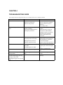
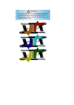
68MICROMAG™
PAINTBALL GUN
MAINTENANCE MANUAL
and
TROUBLE-SHOOTING GUIDE
PRO-TEAM PRODUCTS, INC.
Technical Information: (904) 437-3375
[email protected]
Fax: (904) 437-7108
MAINTENANCE MANUAL
FOR THE 68MICROMAG
68MICROMAG
68MICROMAG ARENABALL, ARENABALL PLUS, ARENABALL DELUXE
68MICROMAG COMPETITION, COMPETITION PLUS, COMPETITION DELUXE
68MICROMAG TOURNAMENT, TOURNAMENT PLUS, TOURNAMENT DELUXE
ReTro Valve 68MICROMAG TOURNAMENT, TOURNAMENT PLUS, TOURNAMENT DELUXE
68MICROMAG 2000 COMPETITION, COMPETITION DELUXE
68MICROMAG 2000 TOURNAMENT, TOURNAMENT DELUXE
68MICROMAG ARENABALL, ARENABALL DELUXE
RetroValve 68MICROMAG 2000 COMPETITION, COMPETITION DELUXE
TABLE OF CONTENTS
CHAPTER 1. INTRODUCTION
1-1.
Description
1-2.
Technical Data
1-3.
Components
1-4.
Tools
CHAPTER 2. OPERATION AND FUNCTION
2-1.
Operation
2-2.
Safety
2-3.
Loading
2-4.
Unloading
2-5.
Operation Cycle
2-6.
Removing the Propellant Source
2-7.
Replacing the Propellant Source
2-8.
Filling the Propellant Source
2-9.
Adjusting the Velocity
2-10.
Adjusting the Input Pressure
CHAPTER 3. MAINTENANCE
3-1.
3-2.
3-3.
3-4.
Disarming the Gun
Basic Maintenance
Complete Disassembly
Cleaning and Lubrication
CHAPTER 4. TROUBLE-SHOOTING GUIDE
4-1.
CHAPTER 5. ACCESSORIES
CHAPTER 6. CUSTOMER SERVICE
6-1. Pro-Team Products Warranty
6-2. Repair Guidelines
6-3. Service
MICROMAG, 68MICROMAG, 68MICROMAG COMPETITION, 68MICROMAG TOURNAMENT,
68MICROMAG ARENABALL, RetroValve 68MICROMAG, 68MICROMAG 2000, MILLENNIUM
SERIES, STEALTH, PRO-SERIES, PRO-DOT, ARMSON, PRO-FEED, PRO-FLOW, f/x, ACCURIZER,
PRO-RING, PRO-WASH, PRO-PLUS, PRO-CLEAN, and PRO-LUBE are trademarks of PRO-TEAM
PRODUCTS. 68AUTOMAG, RT AUTOMAG, MINIMAG and A.I.R. are trademarks of AIRGUN
DESIGNS Inc. AUTOCOCKER is a trademark of wOrr Games Products Inc.
CHAPTER 1
INTRODUCTION
This chapter provides a description of the 68MICROMAG, its components and general information
regarding its operation.
1-1 DESCRIPTION
The 68MICROMAG (and its variants - Competition, Tournament, Arenaball, Plus and Deluxe,
ReTroValve, Micromag 2000) is a lightweight, compact, semiautomatic paintball gun manufactured under
license from AIRGUN DESIGNS INC.,(makers of the 68AUTOMAG, MINIMAG, RT AUTOMAG, RT
PRO and E-MAG paintball guns).
Like the 68Automag, the 68MICROMAG utilizes an A.I.R. valve (Advanced Integrated Regulator) as its
main operating component. With the exception of the body, feed and barrel (see FIGURE 1 ) all
components of the 68MICROMAG and the 68MICROMAG A.I.R. valve are interchangeable with AirGun
Designs Automag components.
The 68MICROMAG has been designed to shoot ONLY 68 caliber paintballs.
The 68MICROMAG can utilize either C02, compressed NITROGEN or compressed AIR as a propellant
source.
ReTroValve versions of the 68MICROMAG may only use compressed Air or Nitrogen as power sources.
The 68MICROMAG utilizes wOrr Games Products style AUTOCOCKER threaded barrels.
Additional features of the 68MICROMAG include a ball detent integrated into the gun body, a removeable
powerfeed or a fixed Vertical feed and a compact, aluminum body.
1-2 SPECIFICATIONS
The technical specifications for the 68MICROMAG are as follows:
a. Gun
Length (without barrel)
Height (without loader or tank)
Weight Unloaded (without barrel)
Weight Loaded (20oz Tank, 200 round
loader)
b. Paintball Ammunition
Caliber
Weight
c. Operational Characteristics
Action
Sights
Input Pressure
8 inches
9 inches
2 Lbs., 5 OZ
6 Lbs., 7 OZ (approximately)
.68
3.5 grams (maximum)
Semiautomatic
Optional, 3/8" Dovetail Mount
650 - 850 psi
Maximum Approved Muzzle Velocity
Rate of Fire
300 fps
12.6 rounds per second maximum
1-3. COMPONENTS
The major components of the 68MICROMAG (including standard variations) and their purpose are
covered here and are shown in Figures 1 thru (x).
a. Gun Body
b. Grip Frame
c. A.I.R. valve assembly
d. Bottomline ASA adapter or Vertical ASA adapter (on some models only)
e. Barrel
f. Sight Rail
g. Ball Detent
h. Powerfeed
i. Remote Quick-Disconnect fitting from valve (some models)
a. GUN BODY. The gun body assembly serves as the chassis for all of the gun's components.
b. GRIP FRAME. The grip frame attaches to the gun body and holds the trigger, safety and Bottomline
ASA adapter assemblies.
c. A.I.R. VALVE. The A.I.R. valve consists of the regulator, the ON/OFF assembly, the POWER TUBE
assembly and the BOLT assembly. The regulator is located at the rear of the valve assembly and
incorporates the VELOCITY ADJUSTER (see FIGURE ). The ON/OFF assembly controls the gas flow
between the regulator and the gun (see FIGURE ). The POWER TUBE assembly, along with the BOLT
assembly push the ball into the barrel and releases the gas which fires the ball.
d. RETROVALVE. This variation is similar to the A.I.R. valve in construction, but is a more advanced
design which incorporates a rapid trigger return system.
d. BOTTOMLINE ASA ADAPTER. This fitting receives the CO2 tank (as well as some regulated
compressed N2 or compressed air systems) in a 'back bottle' or 'shoulder stock' mount and delivers gas to
the valve through its hose connection. It can also be connected to a 'remote tank hook-up' with the use of
an additional adapter.
e. VERTICAL ASA ADAPTER. This fitting receives the CO2 tank (as well as some regulated HPA
systems) in a vertical or foregrip mount. It can also be connected to the BOTTOMLINE ADAPTER when
used with an expansion chamber or gas-thru foregrip, and many aftermarket foregrips are made to attach to
it as well. It can also be connected to a 'remote tank hook-up' with the use of an additional adapter.
f. BARREL. The Micromag barrel uses the standard Autococker barrel thread. Standard model
MICROMAGs are furnished with a stock barrel. Some models may be furnished with an ARMSON
internally rifled barrel.
g. SIGHT RAIL. The sight rail is integrated into the Micromag's body and will accept all 1/2 inch dovetail
mounts and sights.
h. BALL DETENT. This is a spring operated device mounted below the POWERFEED which prevents
more than one ball from entering the chamber at a single time.
i. POWERFEED. The POWERFEED is attached to the side of the gun body and is used to guide balls
into the chamber and also serves as the attachment point for all paintball feeder elbows.
1-4. TOOLS
a. ASSEMBLY AND DISASSEMBLY. The only tool required for normal assembly and disassembly are:
1/8 inch allen wrench (front frame screw, field strip screw, velocity adjusting nut
b. CLEANING AND MAINTENANCE. Tools required for maintenance and cleaning include those
required for assembly and disassembly and the following:
small pick
cleaning cloth/rag/paper towel
squeegee
Pro-Lube or similar paintball gun lubricant
Pro-Wash barrel brush or other recommended barrel brush
Pro-Clean barrel cleaner (recommended)
Pro-Plus barrel treatment (recommended)
Medium phillips head screw driver
CHAPTER 2
OPERATION AND FUNCTION
This chapter discusses the operation of the 68MICROMAG and its' function when gassed and loaded.
2-1 OPERATION
The 68MICROMAG's operations include loading, unloading, gassing, degassing and shooting the paintball
gun. The 68MICROMAG uses a high pressure pneumatic regulator and valve to fire a .68 caliber paintball.
A CO2 or a regulated compressed N2 or compressed air tank is attached to the regulator via a pressure
hose. The regulator reduces the operating pressure which is passed on to the valve. The valve itself
contains an additional regulator which is used to adjust the gun's velocity. Once the trigger is pulled, the
passage between the regulator and the valve is closed and the bolt is released by the sear. This action
simultaneously pushes the bolt forward, chambering a paintball, and releases the gas which fires the ball.
2-2. SAFETY
Maintaining a paintball gun safely requires that the operator is always aware of the gun's current condition
(either loaded, unloaded, charged with gas or uncharged) and that the proper safety precautions are
followed on a regular basis.
Before attaching a pressure source to the gun, the following steps must be taken:
a. moving the trigger safety to 'safe': this blocks the trigger, preventing the gun from firing
b. Turning the gun upside down to drop any balls in the chamber back into the feeder and then turning the
powerfeed plug to the blocking or off position: (See Diagram ). This prevents balls in the feeder from
dropping into the chamber.
WARNING: unless the ball which was in the chamber is dropped out, the gun will remain capable of
discharging a paintball.
c. placing a barrel plug in the barrel.
WARNING: if barrel plugs are improperly inserted the barrel plug itself can be fired.
WARNING: it is recommended that only barrel plugs made for this purpose and for the specific barrel
be used.
As an added precaution, please disconnect the pressure source and degass the gun following use.
WARNING: unless the gun is degassed, enough pressure may remain in the valve to fire several shots
The 68MICROMAG is charged and ready to fire whenever a pressure source has been connected to the
regulator and the passage between the tank and the regulator has been opened. (Some compressed N2 and
compressed air tank systems are supplied with on/off valves. In this case it will be necessary to connect the
tank to the gun and then open the valve.)
WARNING: Whenever and where ever paintball guns are used it is mandatory to use Paintball
Approved Safety Goggles and Masks, unless in an area specifically designated otherwise.
WARNING: Whenever and where ever paintball guns are used it is mandatory to use Paintball
Approved Barrel Plugs.
WARNING: Never place your finger on the trigger or inside the trigger guard unless you are planning to
fire the gun.
WARNING: Never look down the barrel of a gun. If you are working on the gun (for maintenance or
cleaning purposes) it is highly recommended that you wear paintball approved safety goggles.
WARNING: Never attempt repairs, cleaning or maintenance on a gun which remains under pressure.
Always remove the pressure source and degas the gun before working on it.
To completely render the 68MICROMAG 'Safe', it is recommended that ALL four safety procedures be
used simultaneously.
2-3. LOADING
To load the 68MICROMAG, attach an elbow to the feed port (see Diagram) and attach a feeder (several
different models are available) to the elbow. Load paintballs into the feeder and insure that the powerfeed
plug (see Diagram) is turned to the ON/FEED position.
If an agitating or electronic feeder is being used, insure that the power to the feeder has been turned on to
insure proper feeding of paintballs.
2-4. UNLOADING
To unload the 68MICROMAG, first turn the entire gun upside down in order to allow any balls which are
in the chamber to drop out. Visually inspect the chamber to insure that all paintballs have dropped out. If a
paintball remains in the chamber, gently shake or tap the gun to knock it out. Next, turn the powerfeed
plug to the BLOCKED or OFF position. Making sure that you are in an area in which you are allowed to
discharge a paintball gun, make sure that any other people in the area are wearing their goggles, point the
gun towards a safe location and fire once in order to discharge any paintballs which may remain in the
chamber.
Next, turn off or disconnect the propellant source.
Place a barrel plug securely in the barrel.
Finally, remove the paintballs from the feeder.
2-5. OPERATION CYCLE
Understanding how the 68MICROMAG operates is a key to correcting any problems which may occur and
to using the gun properly and effectively.
The gun's cycle begins when the propellant source has been attached to the gun and opened, allowing gas to
flow from the tank into the gun's regulator. Gas flows from the regulator, through the ON/OFF chamber
and into the valve.
When the gas flows into the ON/OFF chamber, the gas pressure pushes the ON/OFF PIN, which in turn
depresses the rear of the trigger sear. This action raises the front portion of the sear which captures the bolt
and pushes the trigger into the 'firing position' (Usually audible as a faint 'click').
The bolt, which is held in position by the sear, seals the valve, preventing gas from flowing down the
barrel.
The gun is now ready to fire.
When the trigger is pulled, the following actions occur:
(1) The sear pivots, releasing the bolt and depressing the ON/OFF PIN
(2) The ON/OFF PIN prevents gas from flowing from the regulator into the valve
(3) The bolt is pushed forward by gas pressure from the valve.
(4) The bolt pushes a paintball into the barrel
(5) Once the bolt has traveled completely forward, the gas in the valve is released, firing the ball
(6) The BOLT SPRING pushes the bolt back, where it is again captured by the sear, completing the cycle
and preparing the gun to fire once again.
2-6. REMOVING THE PROPELLANT SOURCE
There are four different basic configurations of propellant source tank attachments. These are:
ASA Bottomline attachment
ASA Vertical attachment
Tank-to-valve attachment
Remote line attachment
Additionally, all of these configurations can be set up with or without a quick-disconnect fitting, with or
without a check-valve (an in-line on/off bleed valve) or a variety of other fittings, such as a reducer or
elbow.
Both CO2 and regulated compressed N2 or compressed air systems, depending upon the manufacturer and
user configurations, can utilize any of these attachments.
CO2 and regulated compressed N2 or compressed air systems which attach directly to the gun (either
vertically or bottomline mount) are removed using the same procedure:
Follow the unloading procedures found in section 2-4. Next (1) Insure that the valve on the tank has been turned to the OFF position if the tank is provided with an
on/off valve. (Consult the tank manufacturer's instructions for this procedure.)
(2) Point the gun barrel in a safe direction.
(3) Grasping the tank firmly, turn the tank counter-clockwise. Make sure to observe the valve and insure
that the valve is turning with the tank. (If the valve is NOT turning with the tank, STOP IMMEDIATELY
and seek qualified assistance.)
(4) Approximately every quarter to half turn of the tank, pull the trigger; this allows you to relieve pressure
on the tank's o-ring, giving the o-ring longer life and making the tank easier to remove.
(5) When the tank valve has been unscrewed approximately half-way, any gas remaining in the gun will be
able to vent out of a small relief hole which is built in to the bottomline or vertical adapter.
WARNING: Loose valves on propellant source tanks can be extremely dangerous. It is of the utmost
importance that you insure that the valve unscrews from the gun, and does not unscrew from the tank, when
removing the tank. You can make this procedure safer by placing a mark on the valve and the neck of the
tank where the two meet: if the two halves of the mark separate at all during removal, you can easily
observe it by watching the mark. Nail polish or a flourescent paint should be used to make this mark, as
can an indelible, magic marker made for use on metal.
You can also maintain safer tanks by checking the valve every time prior to filling: using your hands
ONLY, attempt to remove the valve from the tank; if the valve moves or unscrews from the tank, do not
fill the tank.
CO2, regulated compressed N2 or compressed air systems which attach directly to the gun's valve are
removed using a different procedure:
(1) Insure that the valve on the tank has been turned to the OFF position. . (Consult the tank
manufacturer's instructions for this procedure.)
(2) Use the manufacturer-supplied bleed, line cut-off or slidecheck valve to discharge any residual pressure
remaining in the gun.
NOTE: If there is no bleed, line cut-off or slidecheck valve supplied with the system, the gun must be fired
in order to discharge the remaining gas. If the tank itself does not have an on/off valve, all of the gas
remaining in the tank will have to be discharged before the tank can be removed from the gun.
NOTE: Some tank configurations are not supplied with an ON/OFF or with a bleed valve. In this case it is
not possible to disconnect the tank from the gun without discharging all pressure in the tank.
2-7. REPLACING THE PROPELLANT SOURCE
CO2 and regulated compressed N2 or compressed air systems which screw directly into the gun are reattached using the following procedure:
(1) Visually inspect the bottle's o-ring (see diagram); replace the o-ring if it is cut, dented or torn. Insure
that the threads are clean and that the valve is free of dirt and obstructions. Place a drop or two of Pro-Lube
or silicon grease on the o-ring
(2) Place the safety of your gun in the 'Safe' position. Turn the powerfeed plug to the OFF/Blocked
position.
(3) Inspect the ASA adapter and insure that it is free of dirt and obstructions and that the internal threads
are clean. Holding the bottle in an upright position, line the bottle's threads up with the ASA adapter
(vertical or bottomline), insert the bottle into the ASA adapter and turn clockwise until the valve threads are
fully seated.
(4) Continue to turn the tank clockwise, tightening it until it is hand-tight.
(5) If the tank valve has an ON/OFF, turn the ON/OFF valve to the ON position. This will charge the gun.
If there is no ON/OFF, the valve will automatically open once it is in the proper position. Gas entering the
gun's valve will be audible.
CO2 and regulated compressed N2 or compressed air systems which connect directly to the gun valve may
be equipped with a Quick-Disconnect fitting. Before attaching the quick-disconnect, inspect the inside of
the female half of the fitting and insure that it is clean and free from dirt. A drop of Pro-Lube can also be
placed inside the fitting to lubricate the o-ring inside. Inspect the outside of the male half of the fitting and
make sure that it is clean and free from nicks, dents and scratches. Follow the manufacturers instructions
for attaching a tank with this configuration. For systems with cut-off and bleed valves, it will be necessary
to open those valves to permit gas to flow from the tank and into the gun.
2-8. REFILLING THE PRESSURE TANK
Pressure tank fills must be performed by a qualified technician according to approved industry practices.
Please obtain fills at local facilities which provide these services.
2-9. ADJUSTING THE VELOCITY
The 68MICROMAG'S velocity is adjusted by turning the VELOCITY ADJUSTING NUT located at the
rear of the A.I.R. valve (see diagram).
NOTE: To properly adjust the gun's velocity a chronograph (velocity measuring device) will be required.
To adjust the velocity:
(1) Insert the 1/8 inch allen wrench into the VELOCITY ADJUSTING NUT
(2) To INCREASE the velocity, turn the Velocity Adjusting Nut CLOCKWISE
(3) To DECREASE the velocity, turn the Velocity Adjusting Nut COUNTER-CLOCKWISE
(4) After making the adjustment, fire several single shots (three to five) over the chronograph and observe
the reading.
(5) Repeat steps 1 thru 4 as required.
NOTE: The 68Micromag's velocity can be adjusted over a wide range. A small adjustment of
approximately 1/4 turn will change the velocity by as much as 30 feet per second or more.
WARNING: Shooting velocities in excess of 300 Feet Per Second are potentially illegal and extremely
dangerous.
NOTE: In the event that the 68MICROMAG's valve pressure has been adjusted too high, the PRESSURE
RELIEF VALVE will vent gas out through the back of the gun. This is a safety feature built into the gun
and is NOT user adjustable. Should the gun be venting gas out the rear of the valve:
Adjust the velocity by turning the VELOCITY ADJUSTING NUT a full turn COUNTERCLOCKWISE
If gas is still venting from the rear of the velocity adjuster, continue to turn the velocity adjusting nut
counterclockwise until gas no longer vents.
Chronograph the gun
Adjust accordingly.
If air continues to vent out the back of the gun, seek assistance from a qualified technician.
2-10. ADJUSTING THE PROPELLANT TANK INPUT PRESSURE
CO2 tanks require no input pressure adjustment.
Regulated compressed N2 or compressed air tanks MAY require adjustment. Please refer to the
manufacturer's product guide for this information.
An input pressure of 650 psi (pounds per square inch) is adequate to supply the gun with working pressure.
However, in order to avoid fluctuations in gun pressure and to prevent 'shoot-down' problems (the velocity
of each shot drops lower in rapid-fire situations) it is recommended that the input pressure be set between
750 and 900 psi.
Lower input pressures will increase the number of shots you will get from a tank, but will also increase
shot-to-shot velocity fluctuations and may increase the incidence of shoot-down.
Higher input pressures will decrease the number of shots from a tank, and will also reduce shot-to-shot
velocity fluctuations and decrease the chances of shoot-down.
NOTE: some regulated compressed N2 or compressed air systems are supplied with 'pre-set' regulators.
These regulators output a fixed pressure and can not be adjusted. In most cases these types of tanks are set
to output between 800 and 850 psi, which should be more than adequate for most users. If you are using
one of these products and feel that you need a higher output pressure from the tank, please consult the
manufacturer.
CHAPTER 3
MAINTENANCE
Proper maintenance of your 68MICROMAG is important to insuring proper function and long life. This
chapter discusses the correct procedures for cleaning, lubricating and maintaining the gun.
3-1. Disarming the Gun
Follow the procedures found in Sections 2-2 SAFETY, 2-4 UNLOADING and 2-6 REMOVING THE
PROPELLANT TANK for instructions on how to disarm the gun prior to performing maintenance and
cleaning operations.
WARNING: Failure to completely render the gun 'SAFE' and failure to completely degas the gun prior
to disassembly can result in injury.
WARNING: Never attempt to clean or work on your gun while it is connected to a propellant source.
NOTE: Cleaning and maintenance is best performed in a clean, well-lit environment which provides
enough stable surface area to lay out parts and tools. For additional safety, it is recommended that you
wear paintball-approved goggles while working on your gun.
3-2 Basic Maintenance
Basic maintenance of your 68Micromag consists of two operations - proper cleaning and proper
lubrication.
Cleaning is easily accomplished using low-residue paper towel or cleaning cloth, water and or alcohol.
Dirt, paint and excess lubricant should be removed from all surfaces.
Using Pro-Clean, the barrel should be thoroughly washed.
The interior of the gun body and powerfeed can be easily cleaned once the A.I.R. valve assembly been
removed.
The A.I.R. valve assembly should be removed for lubrication on a regular basis; this should be performed
after or just prior to each playing session.
To remove the A.I.R. valve assembly:
Disconnect the hose fitting which is attached to the valve port if it is a quick-disconnect fitting. If there is
no quick-disconnect, the hose will have to remain in place, but it is flexible enough to allow you to remove
the valve.
Remove the Field Strip screw located on the back of the body underneath the valve.
Grasp the A.I.R. assembly and then pull the trigger back. While holding the trigger back, pull the A.I.R.
assembly towards the rear of the gun.
Once the A.I.R. has moved as far as it will go, slightly rotate the valve counter-clockwise.
Pull the A.I.R. valve assembly the rest of the way out of the gun body.
All exterior surfaces of the A.I.R. valve assembly should be cleaned. The bolt and bolt bumper (large oring at the base of the power tube) should be removed from the power-tube and cleaned. The outer surface
of the power tube should be cleaned.
The interior of the body can also be cleaned at this time.
To lubricate the air valve, it is recommended that you use Pro-Lube or Autolube, oils which have been
specifically designed for this gun.
Turn the A.I.R. valve assembly upside down and locate the two holes in the body which are labelled 'OIL'.
Lubricant can be placed in either of these holes. Place two or three drops of lubricant into the A.I.R. valve
assembly.
NOTE: Excessive lubrication can adversely affect the performance of your gun by allowing dirt to
accumulate in the valve.
3-3 Complete Disassembly
General Procedure: Always disassemble your 68Micromag using a clean, well-lit, flat surface. Lay the
various parts out in order as they are disassembled, as the gun will be re-assembled in the reverse order.
Refer to Diagram () for the following sections.
(1) Removing the A.I.R. Valve
Disconnect the hose fitting which is attached to the valve port if it is a quick-disconnect fitting. If there is
no quick-disconnect, the hose will have to remain in place, but it is flexible enough to allow you to remove
the valve.
Remove the Field Strip screw located on the back of the body underneath the valve.
Grasp the A.I.R. assembly and pull it towards the rear of the gun, pulling the trigger at the same time.
Once the A.I.R. has moved as far as it will go, slightly rotate the valve counter-clockwise.
Pull the A.I.R. valve assembly the rest of the way out of the gun body.
(2) Removing the ON/OFF assembly
Grasp the on/off top and pull the assembly up and out of the valve.
Look inside the on/off chamber to determine if either of the on/off bottom o-rings have remained in the
chamber.
Lightly tap the chamber or use a small pick or allenwrench to remove any o-rings which remain in the
chamber.
(3) Disassembling the ON/OFF assembly
Separate the brass on/off bottom from the stainless steel on/off top. Note, this will cause any o-rings which
remain attached to the on/off pin to fall off.
Pull the on/off pin out of the on/off top.
(4) Disassembling the Regulator
Unscrew the rear portion (regulator) of the A.I.R. valve from the forward portion (valve).
Remove the regulator seat (disc-shaped o-ring).
Remove the regulator pin and regulator pin spring (both should pull out together; a pick may be required to
remove the spring).
Unscrew the velocity adjusting nut.
Drop the regulator spring pack out of the regulator body.
Insert the 7/64 inch allen wrench through the hole in the front face of the regulator body. Gently apply
pressure to the allen wrench to push the regulator piston out of the regulator body.
(5) Disassembling the Powertube
Use a nickle, quarter or similar-size coin to unscrew the brass powertube tip.
Use the pick or small allen wrench to remove the powertube spring or spacer.
Use the pick to remove the powertube o-ring.
(6) Disassembling the Sear
Locate the sear pin (see diagram) hole on the side of the 68Micromag body. Your gun may have one of
two versions of the sear pin; the commonest is a pressure-fit pin. The second is a screw-in pin, which can
be identified by the allen hex head which will be visible when looking at the sear pin.
In order to remove the pressure fit sear pin, use the allen wrench to push the sear pin out of the body. The
sear assembly, including the sear, clevis and trigger rod will then drop out of the body.
In order to remove the screw-in sear pin, use the an allen wrench and turn counter-clockwise until the sear
pin is completely out of the body.
(7) Disassembling the Grip
Using the phillips screwdriver, unscrew the two screws in each grip panel to remove the grips.
3-4 CLEANING AND LUBRICATION
(1) Cleaning
Using a pick, remove and inspect all o-rings carefully for abrasion, nicks, cuts or deformations. Replace
any o-rings which are worn with the appropriate replacement.
Following inspection, clean each o-ring using water or alcohol and a soft cloth or paper towel.
Inspect all chambers and air passages for dirt and oil build-up. Gently clean all air passages and chambers
with Pro-Clean or denatured alcohol and a soft cloth or paper towel.
Wipe down the springpack, removing all dirt and oil.
Clean the bolt and bolt spring thoroughly.
Clean the barrel, the breach and the powerfeed using a barrel brush and Pro-Clean. If desired (and
recommended) then treat the barrel with Pro-Plus barrel treatment by placing the treatment on a swab and
working it completely into the barrel.
(2) Lubrication
Once cleaning has been completed, lubricate the following parts:
Springpack: place several drops of Pro-Lube or silcone grease directly onto the springs.
Regulator: drop two to three drops of Pro-Lube into the hole marked -oil- on the side of the regulator.
3-4. REASSEMBLY.
NOTE: A diagram for the reassembly of the ON/OFF valve and has been laser engraved directly onto the
A.I.R. valve body. This can be followed easily by matching the parts to the diagram and assembling those
parts in the order indicated.
(7) Reassembling the Grip
Using the phillips screwdriver, replace the grip panels.
(6) Reassembling the Sear
Please refer to the accompanying diagram for instructions on how to reassemble the sear.
(5) Reassembling the Powertube
Place the power tube o-ring into the power tube and push it as far down as possible.
Drop the powertube spacer or powertube spring on top of the o-ring.
Re-attach the powertube tip (brass piece) using a coin to screw it firmly into place. The powertube tip must
be secure, but not over-tightened.
(4) Reassembling the Regulator
Place the regulator piston, brass bottom IN, into the regulator chamber. Push it into place using the allen
wrench.
Place the spring pack, wide diameter IN, into the regulator chamber.
Screw the velocity adjusting nut back into place.
Place the regulator pin and spring assembly back into the face of the valve. Note: This is pushed into place
SPRING FIRST. The regulator pin fits inside of the small end of the cone-shaped spring.
Place the regulator seat into the round receptacle located on the face of the regulator. NOTE: this seat has
two different sides, one slightly larger than the other. The larger side should be placed against the
regulator, and should 'snap' snuggly into place when assembled correctly.
Screw the two halves of the A.I.R. valve together hand tight, until the 68MICROMAG logo which is laser
engraved on the body is lined up.
(3) Reassembling the ON/OFF assembly
Nest the small teflon o-ring inside the larger urethane o-ring.
Place the brass on/off bottom piece onto the on/off pin.
Push the end of the pin protruding from the brass piece down onto the o-rings so that you create one
assembly.
(2) Replacing the ON/OFF assembly
Push this entire assembly, o-ring end down, into the on/off hole in the A.I.R. valve.
(1) Replacing the A.I.R. Valve
Place the bolt spring over the bolt.
Make sure that the powertube bumper (large, thin o-ring) is in place over the powertube.
Drop the bolt onto the powertube.
Line the A.I.R. valve (bolt end in) up with the back of the gun's body, so that the guide pin (see diagram) is
line up with the slot in the body.
Push the A.I.R. valve into the body, turning it clockwise slightly when the guide pin meets resistance.
Replace the field strip screw.
Reconnect any gas hoses.
CHAPTER 4
TROUBLESHOOTING GUIDE
This chapter has been designed to allow you to identify and correct common problems.
SYMPTOM
Gun will not fire
PROBABLE CAUSE
Gas source not attached, not
charged or not turned on
Safety in 'safe' position
Gun fires but paintballs are not
shot
Powerfeed plug is turned to off
Loader is jammed
Over-sized or misshaped ball is
blocking the powerfeed
Gas leaks out the back of the gun
Velocity is set too high
Gas input pressure is too high
Spring pack may need to be
replaced, contact Pro-Team
Gun fires once and then 'sticks'
Debris around bolt or in
powertube
Powertube spacer too small
Gun leaks down the barrel
Powertube spacer too large
Gun leaks in little spurts like a
lawn sprinkler
Air leaking down the barrel,
extremely hard trigger pull, long
recharge with hot shot
Holding the trigger back stops the
leak
On/Off o-rings are worn, dry or
dirty
Liquid CO2 in valve system
ACTION
Make sure that tank is full
Make sure that tank is attached
Make sure that all valves are
turned on
Move safety to 'fire'
Turn powerfeed plug to the firing
position
Insure that loader is turned on,
that loader is loaded and that
paintballs can move freely from
the loader to the powerfeed
Remove obstructions in the
powerfeed
Degas the gun. Turn velocity
adjusting nut counterclockwise at
least one full turn. Re-gas the
gun and chronograph.
Adjust the tank output pressure so
that it is between 650 and 850 psi
Remove debris
Replace spacer with next longest
size
Replace worn main spring
Replace spacer with next shortest
size
Lubricate and or replace On/Off
o-rings
Degas gun, wait for internals to
warm up
CHAPTER 5
ACCESSORIES
This chapter will acquaint you with the aftermarket accessories and upgrades which can be purchased for
your gun.
NOTE: Numerous manufacturers produce aftermarket products for the 68Micromag. Before purchasing
upgrades or modifications to your gun, check to make sure that doing so does not void your warranty.
STANDARD FEATURES OF THE 68MICROMAG INCLUDE .45 FRAME: Combines the classic .45 comfort and style with quality and performance. Precision
machined, includes safety and f/x/ trigger
WRAPAROUND GRIPS: Fits all 1911 style .45 grips. Diamond-textured and finger-grooved for
comfort and grip.
OPTIONAL FEATURES INCLUDE:
.45 DOUBLE-TRIGGER FRAME: High performance version of the .45 frame, with extended trigger
guard for added safety. Please note that cutting your trigger frame to install a double trigger is potentially
dangerous and WILL void your warranty.
ARMSON FOLDING FOREGRIP: Revolutionary foregrip folds down when you need it and back up for
crawling and other tight spots.
GAS-THRU FOREGRIP: Bolt on gas-thru foregrip constructed of light-weight aluminum
ARMSON STEALTH BARRELS: Internal polygonal rifling. Combines the range and accuracy of the
Pro-Series barrel with sound reduction porting. Rated 4 Stars by PCRI!
EXPANSION CHAMBER: Finest quality x-chamber available. Rated 4 Stars by PCRI!
PRO-DOT SIGHT: Allows two-eye sighting with no loss of peripheral vision. Anodized aluminum body,
high quality internal optics and adjusments for windage and elevation
STRAIGHT FEED ADAPTER: Bolt-on modification replaces the powerfeed for down-the-barrel
sighting.
MILLENNIUM TANK SYSTEM: Compressed N2 or compressed air, light-weight, adjustable regulator
system with 68 cubic inch fiber-wrapped tank or 53 cubic inch aluminum tank. Comes complete with
cradle mounting system
MILLENNIUM COILED REMOTE HOSE: Virtually indestructible KEVLAR coiled hose. Three
years in development. Can handle very high pressure without splitting.
MILLENNIUM DROP FORWARD CRADLE: Shortens the overall length of your gun. Bolt on design.
Perfect for longer bottle systems.
VERITCAL BOTTLE ADAPTER: Bolt on modification for vertical foregrip or bottle mount.
ANGLED BOTTOMLINE Adapter: Precision CNC machined, angled for comfort and to keep liquid
co2 from entering the valve. Fits all standard bottom-line grips.
PRO-FLOW FILTER:In-line filter system featuring replaceable filter elements.
ACCURIZER FOAMIELESS BOLT: Foamieless design with eight straight cut venturi ports for
improved accuracy and polished for reduced friction.
MICROGAUGES: Feature 1/8 NPT thread, neon HI-VIZ faces and overpressurization vent. Available for
low pressure and high pressure.
PRO-FEED ELBOW: Double-clamp design for a no-slip fit. Available for 7/8 or 1" feeders.
PRO-PLUS Barrel Treatment: Proven to improve accuracy. Formulated to gently remove gelatin and
other residue. Leaves behind a protective Teflon coating.
PRO-CLEAN Barrel Cleaner: Specially formulated for paintball with special additives. Safe for all
paintball gun parts.
PRO-LUBE gun oil: Developed specifically for paintball.
PRO-SERIES BARREL PLUG: High-visibility neon colors with an exclusive design which allows
adjustment to fit 'relieved' barrels, as well as standard barrels.
CHAPTER 6
6-1 PRO-TEAM PRODUCTS WARRANTY
PLEASE NOTE: Pro-Team Products is not responsible for, nor does Pro-Team Products warrant or repair
accessories or aftermarket products which are not manufactured by Pro-Team Products or its licensors
(Armson, Airgun Designs, wOrr Games Products), nor is Pro-Team Products responsible for warranting or
repairing equipment which was damaged or destroyed as a result of using such accessories or aftermarket
products with products manufactured by Pro-Team Products.
Pro-Team Products are provided with repair and replacement warranties provided directly from the
licensor(s), as well as Pro-Team Products' own warranty. Pro-Team Products warranties are only extended
to those licensed products which are packaged and sold with the Pro-Team Product they are intended to be
used with.
PLEASE NOTE: Repairs, modifications or upgrades performed by unauthorized individuals or companies
will void any warranty obligation by Pro-Team Products.
PLEASE NOTE: Pro-Team Products will NOT perform any warranty repair or upgrade on any gun or gun
related accessory which has been installed on a gun which has had its trigger guard removed.
WARRANTY:
The A.I.R. valve and its associated components are warranted by AirGun Designs for 90 days following the
ORIGINAL retail purchase: this limited warranty covers parts, labor, manufacturing defects and
malfunctions. It does not cover user abuse or mistreatment.
After 90 days from the original retail purchase, the A.I.R. valve and components are covered under AirGun
Designs punch card warranty program. Each time the A.I.R. valve is sent in to be fixed for a major
problem, one of the stars laser-engraved on the valve will be removed. Once all of the stars have been
removed, the valve will still be repaired by AirGun Designs, but at the owner's expense.
Pro-Team Products also offers its own lifetime repair and service warranty on all of the other parts of the
68Micromag. Parts which are broken due to manufacturer's defect and malfunctions will be repaired at no
charge.
6-2 REPAIR GUIDELINES
Before returning a product for warranty repair, it is essential to call Pro-Team Products and request an
Return Authorization Number. This R.A. number allows Pro-Team Products to track the repair and insures
that it will be returned to its owner as quickly as possible.
Product returned to Pro-Team Products for repairs should include the following:
return address
owner's day-time phone number
brief outline of the problem(s)
R.A. number
Additionally, the R.A. number should be printed on the outside of the shipping box in the following
manner:
ATTENTION WARRANTY REPAIR: R.A. NUMBER ####
6-3 SERVICE
Pro-Team Products will typically return a warranty repair within 24 to 48 hours of receiving it. Pro-Team
Products will cover the shipping costs of returning the product to its owner, using UPS Ground Shipping.
Should you need a rapid return, you will be charged the additional shipping fees.
Please note that guns which are received on a Thursday or a Friday can not be returned that same weekend.