1
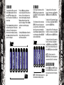
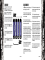
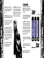
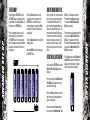
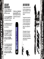
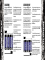
> UPGRADE BOARD
OPERATORS MANUAL
1.
2.
3.
4.
INSTALLATION
USING ZERo.B
ADVANCED SET-UP
WARRANTY INFO
INSTALLING YOUR ZERO.B BOARD
Ensure that your Eclipseblade frame is
powered down and de-gassed. Remove
the barrel and loader to make the frame
easier to work on.
Remove the 9 volt battery (if present), and carefully unplug the cocking
solenoid from the top port on your PCB,
the sear solenoid from the middle port on
your PCB and the Breech sensor from
the bottom port on your PCB.
Using a 5/64th inch (2mm) hex key undo
the three PCB screws that are holding
your original circuit board into the frame.
Remove the old PCB being careful not to
loose the 3 pushbutton caps in the rear
of the frame.
4
Ensure that the three pushbutton caps
are correctly positioned, and position
the Zero-B board into the frame. Loosely
screw in the three PCB screws and
holding the middle pushbutton, tighten
Release the middle pushbutton, and
manually test all three push buttons, to
ensure that the Zero-B board is in the
correct position. Reconnect the cocking
solenoid to the top port on your Zero-B
PCB, the sear solenoid to the middle
port on your Zero-B PCB and the Breech
sensor to the bottom port on your Zero-B
PCB.
Install a fresh 9 volt battery and turn the
Zero B frame on in exactly the same
manner as your old Eclipseblade PCB.
Ensure that the trigger activates the
PCB when pulled, and if not make the
necessary adjustments (see setting the
trigger in either the Eclipseblade or the
E2 manual).
Screw in the three rubber grip screws on
the right hand side of your frame using
the 5/64th inch hex key.
Congratulations! You have now installed
your Zero-B board.
installation
installation
Remove the three grip rubber grip
screws from the right hand side of the
Eclipseblade grip frame and bend the
rubber grip out of the way.
all three screws to correctly position the
Zero-B board.
5
Switching On
Pressing and holding the Select (middle) pushbutton
will switch the frame on. The LCD display will show
the Eclipseblade Zero.B logo. When the pushbutton is
released, the LCD display will show the designated display
screen.
Screen Layout
Breech
Sensor Indicator
Using Zero.B
Using Zero.B
The standard layout of an Eclipseblade Zero.B display is as
follows:
Run Screen Name
Battery Level
Indicator
6
7
THE MAIN MENU
To activate the Main Menu, press and
hold the Select pushbutton. After one
second OFF will be displayed, this is
one of the options on the Main Menu, as
shown below.
Selecting the Back option will return the
display to the display from which the
main menu was selected.
Scroll through the main menu until the
DISPLAY option is displayed and then
press Select. This has now activated the
DISPLAY Menu.
The left hand side of the screen shows
DISPLAY, the name of the option that
you are currently in, whilst the right hand
side of the screen can be changed by
using the Raise and Lower pushbuttons
to scroll through the different DISPLAY
options as detailed below.
8
To display the Game Timer when the
frame is in normal use, simply Select the
TIMER option from the DISPLAY Menu.
To display the Shot Counter when the frame
is in normal use, simply Select the SHOTS
option from the DISPLAY Menu.
To display the Rate of Fire Indicator when
the frame is in normal use, simply Select
the ROF option from the DISPLAY Menu.
To display the Graphics Option when the
frame is in normal use, simply Select
the GRAPHIC option from the DISPLAY
Menu. To return to the Main Menu, scroll
to the CANCEL option and press Select.
NOTE: The Option chosen in the
DISPLAY Menu, will be the designated run
screen when the Zero.B is in normal use.
USING THE DISPLAY MENU
NOTE: The Edit indicators appear on the
left hand side when editing an option.
Both the TIMER and the SHOTS options
from the DISPLAY Menu are covered in
their respective sections in the following
pages.
Using Zero.B
Using Zero.B
Press the Lower (bottom) pushbutton to
scroll down through each of the options
on the menu. Once the last option on
the menu has been displayed, pressing
the Lower pushbutton will cause the first
option to be displayed.
THE MAIN MENU
Press the Raise (top) pushbutton to
scroll up through each of the options on
the menu. Once the first option on the
menu has been displayed, pressing the
Raise pushbutton will cause the last
option to be displayed. Press the Select
pushbutton to select the displayed
option.
9
RATE OF FIRE OPTION
The Rate of Fire (ROF) option is a
means by which you can monitor your
rate of fire whilst using the Eclipseblade
Zero.B. The Rate of Fire screen looks
like this:
With the breech sensor on (and no paint
present), the rate of fire will be limited by
your Cocking Time Out setting as it will
determine the length of time the breech
is held open waiting for a ball to fall into
the breech.
10
Breech
Sensor Indicator
Current
Rate of Fire
Screen Name
Maximium
ROF Achieved
Battery Level
Indicator
The Rate of Fire Indicator records every
pull and release of the trigger over a
period of one second and calculates the
number of valid shots that were fired
during that period.
The current Rate of Fire is displayed in
the top right hand corner. The maximum
Rate of Fire that has been achieved
is displayed in the bottom right hand
corner.
To reset the maximum Rate of Fire
simply push and hold the Lower
pushbutton for a 1 second period.
The GRAPHIC option is a means
by which you can display either the
standard Eclipseblade Zero.B logo or a
custom graphic of your choice that has
been uploaded using the Eclipseblade
Programmer Kit (sold separately). When
GRAPHIC is chosen from the Display
menu, it simply displays the graphic that
you have chosen whilst the frame is in
use.
REFLECTIVE BREECH SENSOR
The Eclipseblade Zero.B is designed to
be used with a Reflective breech sensor.
The breech sensor is an advanced antichop eye. When the breech sensor is
on, the software will prevent the breech
from closing until a ball is detected in
the breech. In this way the Eclipseblade
Zero.B prevents the bolt from closing
prematurely and chopping or trapping a
paintball.
The Eclipseblade Zero.B is compatible
with the Eclipseblade E2 Break-beam
eye kit, available separately from
www.planeteclipse.com
Using Zero.B
Using Zero.B
To use the Rate of Fire screen without
shooting paint, simply switch the breech
sensor off using the Raise pushbutton.
Graphic Option
11
12
The signal from the breech sensor is
represented as a percentage value and
this value is shown at the top right of the
display. As an object passes in front of
the breech sensor (or between the transmitter and receiver in the case of a break
beam sensor) then this value increases,
as the object is removed then the value
decreases. The breech sensor value is
also represented by a graphical bar on
the right-hand side of the screen.
The Sensitivity parameter is shown at the
bottom right of the display and this is also
expressed as a percentage value. When
the breech sensor value is less than the
Sensitivity then the Eclipseblade Zero.B
considers that the breech is empty. When
the breech sensor value is greater than
the Sensitivity then the Eclipseblade
Zero.B considers that the breech is full,
To determine whether or not the breech
sensor is working correctly, simply open
the breech by retracting the bolt and
watch the breech sensor value drop.
Close the bolt and the breech sensor
value will rise.
Setting the
sensitivity Paramater
The factory setting for the Sensitivity
parameter should be fine for most setups
and paint, however you may have to
make adjustments to this parameter
if the breech sensor is not detecting
paintballs.The procedure for doing this is
as follows:
1. Retract the bolt and ensure that nothing is in the breech. Note the breech sensor value in the top right of the display.
2. Drop a paintball into the breech. In
the case of multi-coloured paintballs,
ensure that the darker colour is facing
the breech sensor (not applicable for
break beam sensors). Note the breech
sensor value.
3. Set the Sensitivity parameter to a
value approximately half way between
the two recorded breech sensor values.
To adjust the parameter, press SELECT
to enter the edit mode. Press and release
the Raise pushbutton to increase the parameter value. Press and hold the Raise
pushbutton to increase the parameter
value more rapidly. Press and release the
Lower pushbutton to decrease the parameter value. Press and hold the Lower
pushbutton to decrease the parameter
value more rapidly.
Using Zero.B
Using Zero.B
Scroll through the Main Menu until the
SENSTIV parameter is displayed.
i.e. that a paintball is present.
Break Beam If Fitted
The sensitivity parameter is used to
define the point at which the Eclipseblade Zero.B registers that a ball is in the
breech of the marker.
Break Beam If Fitted
THE SENSITIVITY PARAMETER
13
THE GAME TIMER MENU
Scroll through the main menu until the
TIMER option is displayed and then
press Select. You have now entered the
GAME TIMER Menu.
By using the Raise and Lower pushbuttons, you can scroll through the menu as
illustrated below:
To set the game timer, simply Select the
GAME option.
To set the alarm timer, simply Select the
ALARM option.
To set the starting method of the game
timer, simply Select the START option.
14
Once the GAME option has been
selected from the GAME TIMER Menu,
the preset game time will be displayed
on the right hand side of the screen, the
factory setting for which is 7 minutes and
0 seconds, and the edit indicators also
appear.
To increase the preset game time,
repeatedly press and release the
Raise pushbutton. Each time that the
pushbutton is pressed, the game time
will increase by 10 seconds. To increase
the time more rapidly, press and hold the
Raise pushbutton. The maximum preset
game time is 60 minutes, once this value
has been exceeded the game timer will
wrap around to 0 minutes and 0 seconds.
To decrease the preset game time,
repeatedly press and release the
Lower pushbutton. Each time that the
pushbutton is pressed, the game time will
decrease by 10 seconds. To decrease
the time more rapidly, press and hold the
Lower pushbutton. The minimum preset
game time is 0 minutes and 0 seconds,
once this value has been exceeded
continued ...
the game timer will wrap around to 60
minutes and 0 seconds.
Once you have set the game timer to the
preset time that you require, press the
Select pushbutton to save the value. The
time will briefly flash, indicating that the
time has been accepted.
SETTING THE ALARM TIMER
As well as a game timer we have added
an Alarm feature that allows you to set a
designated time during the game timer at
which the Alarm feature will be activated.
When the game timer reaches the Alarm
time the display will flash repeatedly until
the game time has expired.
Once the ALARM option has been
selected from the GAME TIMER Menu,
the preset alarm time will be displayed
on the right hand side of the screen, the
factory setting for which is 1 minute and
0 seconds.
To increase the preset alarm time,
repeatedly press and release the
Raise pushbutton. Each time that the
pushbutton is pressed, the alarm time will
increase by 10 seconds.
continued ...
Using Zero.B
Using Zero.B
To return to the Main Menu, scroll to the
BACK option and press Select.
SETTING THE GAME TIMER
15
16
To decrease the preset alarm time,
repeatedly press and release the
Lower pushbutton. Each time that the
pushbutton is pressed, the alarm time will
decrease by 10 seconds. To decrease
the time more rapidly, press and hold the
Lower pushbutton. The minimum preset
alarm time is 0 minutes and 0 seconds,
once this value has been exceeded the
alarm timer will wrap around to 9 minutes
and 59 seconds.
preset method of starting the game timer
will be displayed on the right hand side of
the screen, the factory setting for which
is BUTTON.
To change the starting option for the
Game Timer, simply use the Raise or
Lower pushbuttons to scroll through the
menu choices.
BUTTON means that pressing the Lower
pushbutton will start the game timer
(when displayed). TRIGGER means that
pulling the trigger will start the game
timer (when displayed). CANCEL returns
to the GAME TIMER Menu.
STARTING THE GAME TIMER
When TIMER has been selected as the
designated Display screen, the game
timer will be displayed.
Starting the game timer depends on
whether you have chosen BUTTON or
TRIGGER in the START option of the
GAME TIMER Menu (detailed above).
By starting the game timer using your
chosen method, the timer will start to
count backwards, in seconds, towards
zero.
Once you have set the alarm time to the
preset time that you require, press the
Select pushbutton to save the value. The
time will briefly flash, indicating that the
time has been accepted.
If an alarm time has been set, the display
will flash when the timer reaches the
designated alarm time. The display will
continue to flash every two seconds
until the timer reaches 0 minutes and
0 seconds, when GAME OVER will be
displayed until the game timer is reset.
SETTING THE START METHOD
OF THE GAME TIMER
Once the START option has been selected from the GAME TIMER Menu, the
continued ...
If no alarm time has been set, the display
will still flash GAME OVER when the
game timer reaches 0 minutes and 0
seconds.
To stop the game timer, push and release
the Lower pushbutton. The game
timer will pause at whatever time it had
counted down to.
To reset the game timer, press and hold
the Lower pushbutton for 1 second.
The game timer will return to its preset
value. The game timer will also be reset
whenever the Eclipseblade Zero.B is
switched off.
Using Zero.B
Using Zero.B
To increase the time more rapidly, press
and hold the Raise pushbutton. The
maximum preset alarm time is 9 minutes
and 59 seconds, once this value has
been exceeded the alarm timer will wrap
around to 0 minutes and 0 seconds.
17
THE MODE MENU
USING THE MODE MENU
Scroll through the main menu until the
MODE option is displayed and then
press Select. The edit indicators appear
and you you have now entered the
MODE Menu as shown to the right:
In SEMI mode, depressing the trigger will
start the firing cycle as follows:
The Sear solenoid is energised, which
actuates the sear and causes the hammer to be released.
18
The Cocking solenoid is energised,
which causes the cocking block to retract
the bolt and open the breech.
To select the Semi-automatic mode of
operation, scroll to the SEMI option and
press Select.
If the breech sensor is active, then the
cocking block remains retracted for a
preset time (determined by your C T/OUT
value) or until a paintball is detected in
the breech. If the breech sensor is inactive then the cocking block will remain
retracted for a preset time (determined
by your C ON value).
To select the Classic mode of operation,
scroll to the CLASSIC option and press
Select.
To select the Training mode of operation,
scroll to the TRAINING option and press
Select.
The cocking solenoid is de-energised
and the cocking block brings the bolt
forward, closing the breech.
To return to the Main Menu, scroll to the
CANCEL option and press Select.
In CLASSIC mode, depressing the
trigger will again start the firing cycle as
follows:
continued ...
The Cocking solenoid is energised,
which causes the cocking block to retract
the bolt and open the breech.
If the breech sensor is active, then the
cocking block remains retracted until the
trigger is released, and either a ball is
detected by the sensor or a preset time
has elapsed without a ball being detected
(determined by your C T/OUT value). If
the breech sensor is inactive then the
cocking block will remain retracted until
the trigger is released, provided that the
cocking block has been retracted for at
least a preset time (determined by your
C ON value).
The cocking solenoid is de-energised
and the cocking block brings the bolt
forward, closing the breech.
continued ...
Using Zero.B
Using Zero.B
The Eclipseblade Zero.B has three different modes of operation: Semi-automatic
mode, Classic mode and Training mode.
The Sear solenoid is energised, which
actuates the sear and causes the hammer to be released.
19
The Information Menu
CLASSIC mode provides the feel of a
classic mechanical marker, but without
the possibility of “short stroking” the
trigger.
In TRAINING mode, depressing the trigger will start the cocking cycle as follows:
20
If the breech sensor is active, then the
cocking block remains retracted for a
preset time (determined by your C T/OUT
value) or until a paintball is detected in
the breech. If the breech sensor is inactive then the cocking block will remain
retracted for a preset time (determined
by your C ON value).
The cocking solenoid is de-energised
and the cocking block brings the bolt
forward, closing the breech.
Scroll through the main menu until the
INFO option is displayed and then press
Select. You have now entered the Information menu.
By using the Raise and Lower pushbuttons, you can scroll through the INFO
Menu as illustrated below:
In the INFO Menu, the Eclipseblade
E2 Electronic Grip Frame displays the
current version of firmware that it has
programmed into it, and the total number
of shots that the frame has fired. There
is no user interaction in the Information
Menu; it is simply a way of finding out
facts about your Zero.B.
To display the current Version of Firmware being used, scroll to the VERSION
option.
To display the Total number of shots
that your Zero.B has fired, scroll to the T
SHOTS option.
To return to the main menu, scroll to the
BACK option and press Select.
Using Zero.B
Using Zero.B
The Cocking solenoid is energised, which
causes the cocking block to retract the
bolt and open the breech.
In TRAINING mode the firing cycle does
not activate. Training mode provides a
way of using your Eclipseblade Zero.B to
increase your rate of fire and find a trigger set-up that suits your requirements,
without the noise of the marker firing.
21
THE SET-UP MENU
To activate the SET-UP Menu, first
remove the three rubber grip screws
from the right hand side of the frame and
peel back the rubber grip to expose the
Zero.B board inside the frame. Press
and hold the Set-up pushbutton, which is
located on the PCB above the battery.
Press the Lower pushbutton to scroll
down through each of the options on the
menu. Once the last option has been displayed, pressing the Lower pushbutton
will cause the first option to be displayed.
Press the Raise pushbutton to scroll up
through each of the options on the menu.
Once the first option has been displayed,
pressing the Raise pushbutton will cause
the last option to be displayed.
22
Press the Select pushbutton to select the
displayed option.
Selecting BACK will return the display to
Advanced Set-Up
Advanced Set-Up
After one second, TIMING will be
displayed - this is the first option on the
SET-UP Menu as shown below:
the Run Screen from which the SET-UP
Menu was selected.
23
24
Press the Select pushbutton to select the
displayed option.
Selecting BACK will return the display to
the SET-UP Menu.
Scroll through the TIMING Menu until
the Sear Solenoid On Time (SEAR ON)
parameter is displayed.
On Time (SEAR ON) and the edit indicator will disappear from the display to indicate that the value has been accepted.
The current value of the Sear Solenoid
On Time (SEAR ON) is displayed in
milliseconds on the right hand side of the
display.
Press the Select pushbutton to enter the
edit function and the edit indicator will
appear on the display.
Press and release the Raise pushbutton
to increase the Sear Solenoid On Time
(SEAR ON) in 0.1 millisecond increments. Press and hold the Raise pushbutton to increase the Sear Solenoid On
Time (SEAR ON) more rapidly.
Press and release the Lower pushbutton
to decrease the Sear Solenoid On Time
(SEAR ON) in 0.1 millisecond increments. Press and hold the Lower pushbutton to decrease the Sear Solenoid
On Time (SEAR ON) more rapidly.
Press Select to save the Sear Solenoid
Edit Indicator
Press the Lower pushbutton to scroll
down through each of the options on
the TIMING Menu. Once the last option
has been displayed, pressing the Lower
pushbutton will cause the first option to
be displayed.
SEAR SOLENOID ON TIME
Press the Raise pushbutton to scroll
up through each of the options on the
TIMING Menu. Once the first option
has been displayed, pressing the Raise
pushbutton will cause the last option to
be displayed.
Advanced Set-Up
Advanced Set-Up
Scroll through the SET-UP Menu until
the TIMING option is displayed and then
press Select. This will display SEAR ON
the first parameter on the TIMING Menu.
Standard
THE TIMING MENU
25
COCKING SOLENOID ON DELAY
Scroll through the TIMING Menu until the
Cocking Solenoid On Delay (C DELAY)
parameter is displayed.
26
Scroll through the TIMING Menu until
the Cocking Solenoid On Time (CON)
option is displayed.
The current value of the Cocking Solenoid On Time (CON) is displayed on the
right hand side of the display.
Press the Select pushbutton to enter the
edit function and the edit indicator will
appear on the display.
Press the Select pushbutton to enter the
edit function and the edit indicator will
appear on the display.
Press and release the Raise pushbutton
to increase the Cocking Solenoid On
Delay (C DELAY) time in 0.1 millisecond
increments. Press and hold the Raise
pushbutton to increase the Cocking
Solenoid On Delay (C DELAY) time
more rapidly.
Press and release the Raise pushbutton
to increase the Cocking Solenoid On
Time (CON) in 1 millisecond increments.
Press and hold the Raise pushbutton
to increase the Cocking Solenoid On
Time (CON) more rapidly.
Press and release the Lower pushbutton
to decrease the Cocking Solenoid On
Delay (C DELAY) time in 0.1 millisecond
increments. Press and hold the Lower
pushbutton to decrease the Cocking
Solenoid On Delay (C DELAY) time
more rapidly.
indicator will disappear from the display
to indicate that the value has been accepted.
Press and release the Lower pushbutton
to decrease the Cocking Solenoid On
Time (CON) in 1 millisecond increments.
Press and hold the Lower pushbutton
to decrease the Cocking Solenoid On
Time (CON) more rapidly.
Press Select to save the Cocking
Solenoid On Time (CON) and the edit
Advanced Set-Up
Advanced Set-Up
The current value of the cocking solenoid
on delay is displayed on the right hand
side of the display.
COCKING SOLENOID ON TIME
Press Select to save the Cocking
Solenoid On Delay (C DELAY) time
and the edit indicator will disappear from
the display to indicate that the value has
been accepted.
27
COCKING SOLENOID TIME OUT
28
COCKING SOLENOID OFF TIME
and the edit indicator will disappear from
the display to indicate that the value has
been accepted.
Scroll through the timing menu until the
Cocking Solenoid Off Time (C OFF)
option is displayed.
The current value of the Cocking Solenoid Time Out (C T/OUT) is displayed
on the right hand side of the display.
The current value of the Cocking Solenoid Off Time (C OFF) is displayed on
the right hand side of the display.
Press the Select pushbutton to enter the
edit function and the edit indicator will
appear on the display.
Press the Select pushbutton to enter the
edit function and the edit indicator will
appear on the display.
Press and release the Raise pushbutton
to increase the Cocking Solenoid Time
Out (C T/OUT) in 0.1 second increments.
Press and hold the Raise pushbutton to
increase the Cocking Solenoid Time
Out (C T/OUT) more rapidly.
Press and release the Raise pushbutton
to increase the Cocking Solenoid Off
Time (C OFF) in 1 millisecond increments. Press and hold the Raise pushbutton to increase the Cocking Solenoid
Off Time (C OFF) more rapidly.
Press and release the Lower pushbutton
to decrease the Cocking Solenoid Time
Out (C T/OUT) in 0.1 second increments.
Press and hold the Lower pushbutton to
decrease the Cocking Solenoid Time
Out (C T/OUT) more rapidly.
Press and release the Lower pushbutton to decrease the Cocking Solenoid
Off Time (C OFF) in 1 millisecond
increments. Press and hold the Lower
pushbutton to decrease the Cocking Solenoid Off Time (C OFF) more rapidly.
Press Select to save the Cocking
Solenoid Time Out (C T/OUT) setting
Press Select to save the Cocking
Solenoid Off Time (C OFF) time and
the edit indicator will disappear from the
display to indicate that the value has
been accepted.
Advanced Set-Up
Advanced Set-Up
Scroll through the TIMING Menu until the
Cocking Solenoid Time Out (C T/OUT)
option is displayed.
29
THE FILTER MENU
30
Press the Lower pushbutton to scroll
down through each of the options on
the FILTER Menu. Once the last option
has been displayed, pressing the Lower
pushbutton will cause the first option to
be displayed.
USING THE BREECH SENSOR FILTER
Press the Raise pushbutton to scroll
up through each of the options on the
FILTER Menu. Once the first option
has been displayed, pressing the Raise
pushbutton will cause the last option to
be displayed.
Press the Select pushbutton to select the
displayed option.
Selecting BACK will return the display to
the SET-UP Menu.
During the firing cycle, the breech sensor
looks first for an empty breech and then
for a paintball within the breech. Only
when the sensor has detected both conditions will it allow the bolt to close. The
breech sensor software filter allows you
to fine tune the operation of the breech
sensor by allowing you to specify how
long the sensor has to see an “empty”
breech for and how long it has to see a
ball for.
(BALL) in 1 millisecond increments.
Press and hold the Raise pushbutton
to increase the Ball Detection Time
(BALL) more rapidly.
SETTING THE BALL DETECTION TIME
Press Select to save the Ball Detection
Time (BALL) and the edit indicator will
disappear from the display to indicate
that the value has been accepted.
Scroll through the FILTER Menu until the
Ball Detection Time (BALL) option is
displayed.
The current value of the Ball Detection
Time (BALL) is displayed on the right
hand side of the display.
Press the Select pushbutton to enter the
edit function and the edit indicator will
appear on the display.
Press and release the Raise pushbutton to increase the Ball Detection Time
Press and release the Lower pushbutton
to decrease the Ball Detection Time
(BALL) in 1 millisecond increments.
Press and hold the Lower pushbutton
to decrease the Ball Detection Time
(BALL) more rapidly.
Advanced Set-Up
Advanced Set-Up
Scroll through the SET-UP Menu until
the FILTER option is displayed and then
press Select. This will display BALL, the
first option on the FILTER Menu:
31
SETTING THE EMPTY
BREECH DETECTION TIME
32
The current value of the Empty Breech
Detection Time (EMPTY) is displayed
on the right hand side of the display.
Press the Select pushbutton to enter the
edit function and the edit indicator will
appear on the display.
Press and release the Raise pushbutton
to increase the Empty Breech Detection Time (EMPTY) in 0.1 millisecond
increments. Press and hold the Raise
pushbutton to increase the Empty
Breech Detection Time (EMPTY) more
rapidly.
Press and release the Lower pushbutton
to decrease the Empty Breech Detection Time (EMPTY) in 0.1 millisecond
increments. Press and hold the Lower
pushbutton to decrease the Empty
Breech Detection Time (EMPTY) more
rapidly.
Press Select to save the Empty Breech
Detection Time (EMPTY) and the edit
indicator will disappear from the display
to indicate that the value has been accepted.
The trigger has to be pulled for a specific
time in order for that trigger pull to be accepted as a valid trigger pull. The marker
cannot be fired until it has had a valid
trigger pull.
The trigger then has to be released for a
specific time in order for that release to
be accepted as a valid trigger release.
The marker cannot be fired again until
it has first had a valid trigger release
(followed, of course, by another valid
trigger pull).
With the addition of the Trigger Transition software filter, you can minimise
the amount of time for which the trigger
has to be pulled and released in order to
maintain high rates of fire whilst eliminating the risk of “bounce”.
Advanced Set-Up
Advanced Set-Up
Scroll through the FILTER Menu until
the Empty Breech Detection Time
(EMPTY) option is displayed.
USING THE TRIGGER FILTERING
33
SETTING THE TRIGGER PULL TIME
Scroll through the FILTER Menu until
the Trigger Pull Time (PULL) option is
displayed.
34
Note: A Trigger Pull Time (PULL) of
1ms is recommended when using the
additional TT filtering correctly.
Scroll through the FILTER Menu until
the Trigger Release Time (RELEASE)
option is displayed.
indicator will disappear from the display
to indicate that the value has been accepted.
The current value of the Trigger Release
Time (RELEASE) is displayed on the
right hand side of the display.
Note: A Trigger Release Time (RELEASE) of 1ms is recommended when
using the additional TT filtering correctly.
Press the Select pushbutton to enter the
edit function and the edit indicator will
appear on the display.
Press the Select pushbutton to enter the
edit function and the edit indicator will
appear on the display.
Press and release the Raise pushbutton to increase the Trigger Pull Time
(PULL) in 1 millisecond increments.
Press and hold the Raise pushbutton to
increase the Trigger Pull Time (PULL)
more rapidly.
Press and release the Raise pushbutton
to increase the Trigger Release Time
(RELEASE) in 1 millisecond increments.
Press and hold the Raise pushbutton
to increase the Trigger Release Time
(RELEASE) more rapidly.
Press and release the Lower pushbutton to decrease the Trigger Pull Time
(PULL) in 1 millisecond increments.
Press and hold the Lower pushbutton to
decrease the Trigger Pull Time (PULL)
more rapidly.
Press and release the Lower pushbutton
to decrease the Trigger Release Time
(RELEASE) in 1 millisecond increments.
Press and hold the Lower pushbutton
to decrease the Trigger Release Time
(RELEASE) more rapidly.
Press Select to save the PULL value
and the edit indicator will disappear from
Press Select to save the Trigger
Release Time (RELEASE) and the edit
Advanced Set-Up
Advanced Set-Up
The current value of the Trigger Pull
Time (PULL) is displayed on the right
hand side of the display.
SETTING THE TRIGGER RELEASE TIME
the display to indicate that the value has
been accepted.
35
36
The Zero.B incorporates an advanced
debounce (anti-bounce) algorithm known
as the Trigger Transition Filter (TT Filter),
which is fully adjustable and can be used
to completely eliminate trigger bounce.
The TT Filter works by analysing each
trigger pull and determining whether
that trigger pull is a legitimate pull of the
trigger by the user, or one that has been
caused by the gun bouncing, in which
case the algorithm will take steps to stop
that bounce.
There are two adjustable parameters
associated with the TT Filter -
SETTING UP THE TT FILTER
TT BAND
In order to optimise the TT Filter it is necessary to have the TT Band parameter
as high as possible and the TT Tolerance parameter as low as possible -
TT TOLERANCE
1. Select the TT Band parameter.
Observe that the graphical bar rises and
falls as the trigger is pulled and released.
The actual value of the bar is displayed
in the top right of the display.
This parameter defines the operating
range of the TT Filter in terms of trigger
movement. The larger the TT Band, the
less the gun is able to bounce.
This parameter defines how strictly the
TT Filter applies its debounce rules - the
lower this value, the less the gun is able
to bounce.
2. Set the Post-travel Trigger Stop
as required and ensure that the bar is
as close to 100% as possible when the
trigger is fully depressed against the set
screw.
3. Set the Pre-travel Trigger Set Screw
as required and ensure that the bar is as
close to 0% as possible when the trigger
is fully released against the set screw.
4. Set the Trigger Return Force Set
Screw as required, making the return
force as strong as possible without compromising the ‘feel’ of the pull.
5. Adjust the TT Band parameter, shown
in the bottom right of the screen, and observe the movement of the two horizontal
markers by the side of the bar. As the
TT Band is decreased these markers
move closer together, and as the TT
Band is increased these markers move
further apart. Set the TT Band such that
when the trigger is fully depressed the
bar settles above the upper marker and
when the trigger is fully released the bar
settles below the lower marker. This ensures that the TT Band operates across
the full range of the trigger pull
6. Select the TT Tolerance parameter.
With the gun gassed up and preferably
fitted with loader and firing paint, try to
get the gun to bounce by pulling the trigger very slowly. If the gun does bounce
then reduce the TT Tolerance until it
no longer does so. If the gun does not
bounce then increase the TT Tolerance
until the gun does bounce and then
reduce the TT Tolerance again until the
bouncing stops.
Whilst this set up should completely
eliminate bounce, it may result in a trigcontinued ...
Advanced Set-Up
Advanced Set-Up
USING THE TRIGGER
TRANSITION FILTERING
37
38
Note: The fastest way to shoot an E2 is
to walk the trigger with two or more fingers. Feathering (not fully releasing) the
trigger will cause the TT Filter to reduce
the rate of fire in order to eliminate what
it perceives as trigger bounce.
THE BREECH SENSOR TYPE
The Breech Sensor Type parameter
defines which type of breech sensor is
fitted to the marker.
REFLECTV refers to the standard Reflective Breech Sensor which is supplied
with the Eclipseblade / Eclipseblade E2.
BRK BEAM refers to the Break-beam
Breech Sensor system, sold separately.
NONE allows the Zero.B to be used with
no Breech Sensor fitted.
Note: When selecting NONE , the Zero.B
will power up with the breech sensor
permanently disabled and the user will
not be able to switch it on or off.
SELECTING THE BREECH
SENSOR TYPE
Scroll through the SET-UP Menu until the
Breech Sensor Type (BS TYPE) option
is displayed. The current breech sensor
choice is displayed. Pressing Select
enters into the edit feature of the Breech
Sensor Type (BS TYPE) Menu.
Press the Lower pushbutton to scroll
down through each of the options on the
Breech Sensor Type (BS TYPE) Menu.
Once the last option has been displayed,
pressing the Lower pushbutton will
cause the first option to be displayed.
Press the Raise pushbutton to scroll
up through each of the options on the
continued ...
Advanced Set-Up
Advanced Set-Up
ger pull that is not ideally suited to the
user, in which case it will be necessary
to make adjustments to the trigger and
then modify the TT Filter parameters
accordingly.
39
Advanced Set-Up
Press the Raise pushbutton to scroll
up through each of the options on the
POWER Menu. Once the first option
has been displayed, pressing the Raise
pushbutton will cause the last option to
be displayed.
Press the Select pushbutton to select the
displayed option.
Press the Select pushbutton to select the
displayed option.
Selecting BACK will return the display to
the SET-UP Menu.
Selecting BACK will return the display to
the SET-UP Menu.
THE POWER MENU
The POWER Menu gives the user options to adjust the power saving settings
of their Zero.B. It is possible to change
the characteristics of both the LCD backlight and of the Auto-off feature using the
POWER Menu.
USING THE POWER MENU
Scroll through the SET-UP Menu until
the POWER option is displayed and then
press Select. This will display LIGHT, the
first option on the POWER Menu:
Press the Lower pushbutton to scroll
down through each of the options on
the POWER Menu. Once the last option
has been displayed, pressing the Lower
pushbutton will cause the first option to
be displayed.
continued ...
Advanced Set-Up
40
Breech Sensor Type (BS TYPE) Menu.
Once the first option has been displayed,
pressing the Raise pushbutton will cause
the last option to be displayed.
41
THE BACKLIGHT MENU
42
Press the Lower pushbutton to scroll
down through each of the options on the
Backlight (LIGHT) Menu. Once the last
option has been displayed, pressing the
Lower pushbutton will cause the first
option to be displayed.
SELECTING THE AUTO-OFF TIME
Press the Raise pushbutton to scroll up
through each of the options on the Backlight (LIGHT) Menu. Once the first option
has been displayed, pressing the Raise
pushbutton will cause the last option to
be displayed.
Press the Select pushbutton to select the
displayed option.
To have the backlight permanently on,
select the ON option.
To have the backlight permanently off,
select the OFF option.
To activate the backlight every time the
trigger is pulled, select the TRIGGER
option.
Scroll through the POWER Menu until
the Auto Off-time (AUT OFF) option is
displayed and then press Select. This
will display the current Auto-off option on
the Auto Off-time (AUT OFF) Menu:
Press the Lower pushbutton to scroll
down through each of the options on
the Auto Off-time (AUT OFF) Menu.
Once the last option has been displayed,
pressing the Lower pushbutton will
cause the first option to be displayed.
Press the Raise pushbutton to scroll up
through each of the options on the Auto
Off-time (AUT OFF) Menu. Once the
first option has been displayed, pressing
the Raise pushbutton will cause the last
option to be displayed.
Press the Select pushbutton to select the
displayed option.
To set the Zero.B to never power down
after a period of inactivity, select the
NEVER option.
To set the Zero.B to power down after ten
minutes of inactivity, select the 10 MIN
option.
To set the Zero.B to power down after
twenty minutes of inactivity, select the 20
MIN option.
To activate the backlight every time a
push button is depressed, select the
BUTTON option.
To set the Zero.B to power down after
thirty minutes of inactivity, select the 30
MIN option.
Selecting CANCEL will terminate the selection mode leaving the original choice
unchanged.
To set the Zero.B to power down after
sixty minutes of inactivity, select the 1
HOUR option. Selecting CANCEL will
terminate the selection mode leaving the
original choice unchanged.
Advanced Set-Up
Advanced Set-Up
Scroll through the POWER Menu until
the LIGHT option is displayed and then
press Select. This will display the current backlight option on the Backlight
(LIGHT) Menu:
43
Full Name
THE FACTORY SETTINGS PARAMETER
Advanced Set-Up
As a guideline, we would recommend
that:
44
When using the Zero.B on a standard autococker with standard pneumatics using
a gravity fed loading device, the frame
should be set at Factory Slow.
When using the Zero.B on a mid-range
autococker, such as an Eclipse Pro
Series or Pro Series Plus marker using
an electronic loading device, the frame
should be set at Factory Medium.
When using the Zero.B on a top of the
line autococker, with heavily upgraded
pneumatics (Nexus Ram and QEV’s),
such as the Nexus DC2 marker, the
frame should be set at Factory Fast.
As an aside, if the user has chosen to
deviate from the factory settings,
CUSTOM will be displayed as the selected choice.
SELECTING A FACTORY SETTING
Scroll through the SET-UP Menu until
the Factory Setting (FACTORY) option
is displayed and then press Select. This
will display the current Factory option on
the Factory Setting (FACTORY) Menu:
Postal / Zip Code
Press the Lower pushbutton to scroll
down through each of the options on
the Factory Setting (FACTORY) Menu.
Once the last option has been displayed,
pressing the Lower pushbutton will
cause the first option to be displayed.
Press the Raise pushbutton to scroll
up through each of the options on the
Factory Setting (FACTORY) Menu.
Once the first option has been displayed,
pressing the Raise pushbutton will cause
the last option to be displayed.
Press the Select pushbutton to select the
displayed option.
continued ...
WARRANTY REGISTRATION
Address
City
Country
Serial No
Email
Cut along line
The Factory settings option gives the
user a simple way of selecting a group
of factory settings to suit their marker,
without having to individually go through
and adjust each parameter.
Planet Eclipse offers a 6-month limited warranty period
on the Zero.B Board and is warranted to be free from all
manufacturing and production defects for a period of 6
months from the time of original purchase. Warranty cover is
dependant on successful completion, and receipt by Planet
Eclipse Limited, of warranty form either in electronic form
on www.planeteclipse.com or via mail using the warranty
card included in every Zero.B manual. Warranty exemptions
include, but are not limited to, accidental damage, wear and
tear, unreasonable force and perishable components (at our
discretion).
Please complete and return this form with proof of
purchase, within 14 days so that we may validate
your 6 month limited warranty on your Eclipse®
manufactured product. Please return to the address
on the reverse of this form.
I verify that I am at least 18 years of age and I have read the
manual supplied with my Eclipse® Ego and I understand the
safety cautions and warnings that it contains.
(Contact your dealer or Planet Eclipse Limited directly if you
need a replacement set of instructions).
Note: warranty form must be
completed in full to validate warranty.
Signed
To set the Zero.B frame to Factory Slow,
select the SLOW option.
To set the Zero.B frame to Factory Medium, select the MEDIUM option.
To set the Zero.B frame to Factory Fast,
select the FAST option.
Cut along line
Please complete and return in an envelope
Selecting CANCEL will terminate the selection mode leaving the original choice
unchanged.
Advanced Set-Up
It is not possible to select CUSTOM
as an option from the Factory Setting
PLANET ECLIPSE LTD
UNITS 5 to 8 SOUTHFIELD IND EST.
PRAED ROAD
TRAFFORD PARK
MANCHESTER
M171SJ
ENGLAND
(FACTORY) Menu, as this is only
displayed when Factory Settings are not
adhered to.
47
> ECLIPSEBLADE UPGRADE BOARD
> ELIMNATES BOUNCE
> ADVANCED TT FILTER
Eclipse, Planeteclipse, Eclipseblade, the Eclipseblade Logo, the Eclipse E logo, the E2 logo and the
Eclipse grip design are all design trademarks, trademarks or registered trademarks of Planet Eclipse Ltd.
Cocker and Autococker are registered trademarks of Worr Game Products.