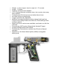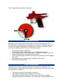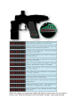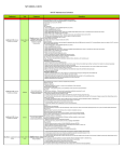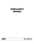
1
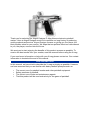
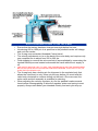
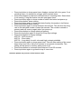
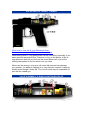
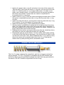
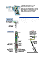
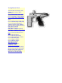
THIS PAINTBALL MARKER IS NOT A TOY! This paintball marker should
be treated as a dangerous instrument and should always be treated with
respect. Never point a paintball marker at anyone not properly attired. This
paintball marker can cause serious bodily injury including, but not limited
to, blindness or even death. Please read all safety instructions and
directions in this manual before using this paintball marker. Always wear
approved safety goggles or an approved mask whenever you handle this
paintball marker!
Do not point or shoot this paintball marker at animals. Do not point or
shoot this paintball marker at any person unless you and your target are
engaged in paintball activities and are wearing proper safety gear including
approved paintball goggles, mask, and pads. Never shoot anyone at close
range! Never load this paintball marker with anything except approved
paintballs. Never put anything down the barrel except paintballs, barrel
squeegees or barrel plugs. Do not attempt to repair this paintball marker
by yourself. Follow all maintenance instructions carefully. If you are unsure
about any aspect of the maintenance procedures contact your local dealer
or Airgun Designs, Inc. at the number located at the end of this manual.
This paintball marker is always armed and cocked when an air supply is
installed. Always engage the safety (located behind the trigger on the grip)
and use an approved barrel bag/sock when an air supply is attached or
installed. Disengage the safety and remove the barrel bag/sock only when
on a playing field, the game has started and all players are wearing proper
safety gear. When the red ring of the safety pin is showing, the safety is off
and the paintball marker will fire.
Always chronograph this paintball marker before using it. Never shoot this
paintball marker when the chronograph readings exceed 300 fps! There is
a blow-off valve incorporated into the valve mechanism that will release air
pressure if pressure exceeds a predetermined amount. This blow-off valve
is factory set and is not user adjustable. Remember to wear proper
approved goggles or masks when chronographing your paintball marker.
USE COMPRESSED AIR ONLY
Your X-mag is designed to run on compressed air only! It will not function
at all on CO2 no matter what hoses, expansion chambers, etc. you use.
We recommend that you purchase a high-quality compressed air tank and
regulator for your X-mag. Working input pressure to the paintball marker is
600 psi to 1000 psi for best performance. Pressures over 1000 psi will
damage the regulator and reduce performance.
BLOW-OFF VALVE
The blow-off valve is self-contained in the regulator piston and is not user
adjustable. It is a safety device for venting gas from the paintball marker
should abnormally high pressure occur in the regulator or air chamber.
Always check your velocity any time the blow-off valve has vented.
FEEDING PAINTBALLS
When firing the paintball marker, it’s important to remain aware of whether
the loader is feeding paintballs at a sufficient rate. Due to the unique
recoiless design of the X-mag, paintballs may not feed because the
marker does not shake the loader. We strongly suggest that you use an
agitator type loader to keep the balls feeding.
BOLT STICK
The bolt can stick forward causing the trigger to lock due to either paint
chips wedging between the bolt and breech or when degassing the
paintball marker, caused by turning off the tank and firing or shooting
those last few blooping shots when the tank is empty. When the bolt sticks
forward the trigger will not come forward. Remove the barrel and use a
SQUEEGEE to push the bolt back until the trigger clicks forward.
EXHAUSTED GAS SUPPLY
The paintball marker will give very little indication that it is running out of
gas; by the time you see the velocity drop you are 20-30 shots away from
total shutdown. Additionally, if you use a compressed air tank with an
on/off valve, make sure you open it all the way.
DO NOT OIL FILL NIPPLE
Do not let oil enter the fill nipple of your air supply. As the bottle is filled,
the oil can vaporize in the bottle and reach flash point due to the
temperature of the incoming pressurized air. This can cause a fire or
potential explosion.
Thank you for selecting the Airgun Designs E–Mag Xtreme electronic paintball
marker. Here at Airgun Designs we strive to continue our long history of producing
quality products and service. Airgun Designs focuses on giving you, the player, the
best possible value for your money. We hope that our policies reflect our commitment
to you, the player, now and into the future.
We want you to start enjoying the benefits of this product as soon as possible. To
receive the best results from your marker, read this manual before using the X-mag
If you need more information or help with your X-mag please contact us. Our contact
information is located at the end of this manual.
OUR ASSUMPTIONS
In this manual, we have tried to describe the X-mag as simply as possible. However,
we have assumed that you are familiar with basic paintball principles such as:
•
•
•
•
The correct use of a paintball marker and other paintball equipment.
Safety practices of paintball.
The correct use of tools and maintenance agents.
That this product will be used exclusively for the game of paintball.
QUICK OVERVIEW OF HOW TO USE THE X-MAG
•
•
•
•
•
Ensure that the battery has been charged overnight before first use.
Introducing 600 to 1000 psi of air pressure to the paintball marker will charge
and cock the marker.
The X-mag uses a standard threaded Cocker barrel.
The velocity adjustment nut is on the back of the valve body and requires only
one complete turn to adjust from 200 to 300 fps.
Field stripping to remove the valve and bolt is accomplished by unscrewing the
knurled field strip screw located underneath the frame while the air supply is
off.
•
THE SAFETY MUST BE “OFF” TO PULL THE TRIGGER BACK AND THE TRIGGER MUST
BE PULLED (WITH SELECTOR SWITCH POINTING FORWARD, 9 O'CLOCK TO “M”) TO
SLIDE THE VALVE BODY OUT.
•
The X-mag body has a locking pin for alignment in the regulator body that
allows the valve body to only come out part way before you must twist the
valve body clockwise to continue sliding out the back. Once removed, the
entire valve and bolt assembly is available for cleaning.
When adjusting the velocity regulator, dry fire the paintball marker several
times before chronographing to allow the regulator piston and spring to seat
properly. Always start below your intended velocity and work your way up.
•
The X-mag is Airgun Designs’ flagship marker. Starting with the worlds fastest
recharging RT valve system and ending with the world’s only manual override
switch the X-mag can’t be beaten for looks and performance.
The X-mag comes in a variety of feed styles to suit every type of play. AGD is the
only marker manufacturer that designs interchangeable bodies into their markers
so when your style changes your marker can too. The X-mag has an aluminum
main body, which incorporates a modular feed system (patent pending). The
modular system allows the whole feed tube to be removed and replaced with a
different style. Currently available are center feed & warp feed modules in left and
right handed versions.
A model of simplicity, the electronic version has only one more moving part over
the mechanical ‘Mag. A solenoid in the grip pulls the trigger to fire the marker on
command from the electronic trigger.
The trigger is one of a kind and uses a magnetic sensor embedded in the grip to
sense the position of the magnet in the trigger. Airgun Designs knows you like to
fine tune your marker so we made the trigger FULLY ADJUSTABLE for stroke and
tension. Many players get the trigger stroke down to a half a millimeter or better.
The single most unique feature of the X-mag is the Manual Override Switch
located just behind the trigger, allowing you to completely bypass the electronics
and fire the marker in manual mode with a flick of your thumb. We like to think of it
as your primary and your backup marker in one! You never have to worry about
dead batteries or broken wires taking you out of a game.
The front grip houses the removable Nickel Metal Hydride battery pack that can
power you through 20,000 shots before recharging. Remove the battery and use
the provided charger to juice up the battery from your car’s cigarette lighter!
The LED display shows total shots, game timer, adjustable firing rate and shots
since turned on.
The system works with standard Autococker barrels which hold the module in
position. When you want to change the module, just unscrew the barrel by a few
turns, remove one module, and replace it with another...It’s that easy!
•
•
•
•
•
•
•
•
•
•
•
•
•
Weight - no tank, hopper, barrel or sight rail - 2.7 pounds
Length - 16 inches
Aluminum 45 Grip frame standard
L.E.D. Display features countdown timer, shot counter, plus many
other features
Tested beyond 20 shots per second without shoot down
No visible wiring or components
Trigger sensitivity fully adjustable
Modular Feed system (patent pending) change feed type from
Center Feed to Warp Feed in seconds; left, center and right feed
modules optional
New Cut & Carve versions now available, machined on a 4th Axis
CNC Mill
Revolutionary MAT system (Magnetically Actuated Trigger)
Accepts standard Autococker barrels
Revolutionary Dual selector, switches from Electric to Manual
operation
Operates on 18v Nickel Metal Hydride (NiMH) rechargeable
battery pack
The X-mag has three modes of operation.
1. MECHANICAL MODE
Indicated by the selector switch positioned so that it points toward the “M” (9
O'clock Position) marked above the trigger on the left side of the grip frame and
the electronic system disengaged. Disengage the electronic system by either
removing the battery pack or turning off the power switch.
•
•
•
•
•
•
This mode is purely mechanical.
No shot count, timer, burst mode, etc. is available in this mode.
This mode provides a “Reactive Trigger”, meaning the trigger is returned
forward by gas pressure supplied from the valve.
There is longer trigger travel and greater effort required to pull the trigger in
this mode.
Partial trigger pulls “half stroking” is possible in this mode.
Emulates Automag RT/Pro
2. ELECTRONIC MODE
Indicated by the selector switch positioned so that it points toward the “E” (6
O'clock position) marked behind the trigger on the left side of the grip frame while
the electronics is turned on.
•
•
•
This mode is “purely” electronically controlled.
The trigger pull will be light and short in this mode.
Each time the trigger is pulled the electronics will activate causing a
complete firing cycle to take place. This mode will not allow “half stroking.”
•
•
•
The shot counter, count-down timer and various other LED indicators are
active in this mode.
The firing cycle is triggered via the Hall Effect Sensor in this mode.
Eliminates the “Reactive Trigger” meaning the trigger is returned via the
return magnet system located above and forward of the trigger.
3. HYBRID MODE
Indicated by the selector switch positioned so that it points toward the “M” (9
O'clock position) marked above the trigger on the left side of the grip frame while
the electronics is switched on.
•
•
•
•
This mode is a mixture or “Hybrid” of Mechanical and Electronic modes.
The firing cycle is controlled electronically and is triggered via the Hall
Effect Sensor.
The trigger is “Reactive” and is returned via air pressure supplied from the
AIR valve pushing the trigger rod forward.
In this mode the Shot Counter, Count-Down Timer and various other LED
indicators are active.
While the marker is powered up display will flash one pixel every four seconds to
show it’s on. When the battery is low it will flash “low bat.” every few seconds.
•
•
•
•
•
•
•
•
•
•
•
•
•
Press top button to show game timer: displays minutes left in the game. If not
counting down, it is waiting for a trigger pull to activate timer.
Press lower button to stop clock and reset timer if counting down. Starts timer
if not running. Firing the marker can also start game timer.
Press top button again to show number of shots fired since last power up.
Press lower button: does nothing
Press top button again to show total shots fired by this marker in its lifetime.
Press lower button: does nothing.
Press top button again to show shots per second limit. This will limit the firing
rate to the indicated number of shots per second. The number is stored in
memory and will come up again when you power up.
Press lower button to change shots per second.
Press the top button again to show Anti Chop Eye settings.
Press lower button to change settings.
ACE 00 – ACE turned off
ACE 01 – Short delay
ACE 02 – Long delay for multi color and high contrast paintballs.
Press top button again to show game timer. This will allow setting of the count
down timer from five to thirty five minutes in one-minute increments. This
setting will be saved in memory when power is off.
Press lower button to increment timer between 5 and 35 minutes.
Press top button again to go back to top of menu tree.
Software updates may not have all the features listed.
Keeping your X-mag clean and well lubricated will ensure years of faithful service.
How often you maintain your marker should be based on playing conditions,
frequency of play, and environment. Sand and dusty environments are harsh on o–
rings and moving parts; playing at facilities near the coast can allow salt in the air to
attack metal parts such as screws. Pay attention to your environment and how it can
affect your playing equipment and create a maintenance schedule accordingly.
Under normal operating conditions we recommend that you clean your marker after
each day of play and lubricate it about once a month.
Always remember to wear approved paintball goggles and mask when cleaning your
paintball marker if the marker is pressurized. After each use a paintball marker
should be field stripped and all the exposed parts cleaned and inspected for wear or
problems. Lightly lubricate all surfaces and reassemble according to instructions.
DO NOT USE “CLEANING” LUBRICANTS FOR FIREARMS OR SPRAYS SUCH AS
“WD-40”.
Lubricate with quality lubricants designed for pneumatic devices such as “Autolube.”
If used regularly, we find that customers who properly lubricate their paintball
markers once a week have the fewest problems. To lubricate your X-mag, apply 6
drops of AUTOLUBE into the air line running into the valve. Then gas up and dry fire
the paintball marker several dozen times with the barrel removed to prevent oil buildup in the barrel. This cycles the oil throughout the marker and provides needed
lubrication to internal parts.
COMPONENTS
The X-mag is made up of seven essential modules:
•
•
•
•
Battery
Grip Frame
ACE Board
PC Board
•
•
•
Electronic Wiring
Valve Assembly
Body
VALVE AND LVL 10 BOLT O-RINGS
Click here to view the O–ring Reference Chart.
Print the document at 100% and use as described.
Determining which o–ring goes where can be confusing; especially if you
have removed several at once. Place an o–ring on the picture of the o–
ring reference chart till you find one the exact same size. Look at the
Identity description to find out which one you have.
Never use the wrong o–ring as it will cause failures and can damage
your marker. It is better to replace an o–ring that you suspect is causing
trouble even though it looks OK. Tiny cuts or wear may be impossible to
see with the naked eye.
VALVE ASSEMBLY O–RING LOCATION BLOW–UP
LVL 10 CARRIER
The diameter of the carrier is identified by a series of
lines and/or dot, carved into the carrier body.
The diameter determines how snugly the o–ring fits
into the carrier.
Refer to the chart for ID to Size relationship.
LVL 10 COMPONENTS
LVL 10 GENERAL INSTALLATION INSTRUCTIONS
1. Disassemble the marker, and remove the all components from the Power
Tube.
2. Install the delrin backing washer (10) into the power tube. This component
prevents the power tube o–ring from being pushed back into the air
chamber in the valve.
3. Lightly oil a power tube o–ring (9) and place it into one of the carriers (8).
Take the bolt (3) and push the carrier, o–ring first, onto the end of the bolt
shaft. If it is hard to push on, try a larger sized carrier; if it slides on too
easily, use a smaller carrier. you want the seal to be snug but provide as
little friction as possible. Carrier sizes are used to compensate for
inconsistencies in o–ring sizes.
4. Install a carrier o–ring (7) onto the carrier and lightly lubricate with oil. Slide
the carrier, containing the power tube o–ring, into the power tube, o–ring
end first.
5. Install the power tube tip (4), ensuring that it has the power tube tip o–ring
(5) is in place. Do not over-tighten the power tube tip!
6. Install the bolt and spring (1) and reassemble the marker.
7. Gas the marker up and listen to determine if it is leaking down the power
tube. If you hear a leak, push on the front of the bolt using a squeegee. If
the leak changes tone try using the next smaller size carrier. When you no
longer hear a leak move to the next step.
8. Disassemble the marker and remove the power tube tip. Install two shims,
and make sure they are sitting flat so they don't get bent.
9. Reassemble and gas up the marker. Fire the marker while lightly pushing
on the front of the bolt using a squeegee. You should hear air start to vent
out the front of the bolt. If not, add an additional shim. If you add too many
shims the marker will constantly leak out the front. If you find that the
marker locks up after pinching a ball, add another shim.
ORIGINAL VALVE COMPONENTS
The LVL 10 system replaces the original bolt, which is no longer produced by
Airgun Designs. The LVL 10 system is compatible with all AGD markers and
should be used to prevent paintball breakage from balls that may get pinched in
the breech. DO NOT install an original bolt into the X-mag.
The Grip Frame contains all of the
electronics that run the X-mag.
Make sure that the sear screw is removed
before separating the grip frame from the
body. Failing to do so may bend the
solenoid sear shaft cause a failure.
TIP
Use an Allen Key to remove or install magnets
into the top of the Grip Frame. The magnets will
be attracted to the iron in the key, making
removal very simple.
CHARGER AND BATTERY
BATTERY LEDS
HOW TO CHARGE THE BATTERY
•
Unscrew and remove the battery retaining screw (interchangeable with a
•
•
•
•
•
field strip screw).
Slide the battery down and off the battery rail (located in front of the trigger
guard).
Slide the battery into the charging unit and press the field strip screw
through the hole in the charging unit and into the battery.
Insert one end of the power cord adapter into the charging unit and the
other into a 12 volt power source such as an automobile cigarette lighter.
While the battery is charging the light on the charging unit will appear red.
The light will change to green when it is in trickle charge mode; trickle
charge mode occurs when the battery is about 85-90% charged. At this
point, the battery is ready for play. Trickle charge an additional 3-4 hours, if
desired, to attain 100% charge.
Some batteries may cause the green light to come on in a few minutes.
Continue to trickle charge for several hours for a full charge.
PC BOARD INFORMATION
•
•
•
•
•
•
There are no user adjustable components
located on the E–Mag Xtreme PC Board.
Keep all liquids away from the components on
the board at all times.
Make sure that no wires are pinched when
assembling and disassembling the marker.
This can cause the insulating plastic cover on
the wire to break, exposing the inner
conductive wire to the frame of the marker.
This in turn can cause a short or general failure
of the marker.
The frame carries the negative DC from the
battery to the PC Board. Make sure that the
screw that holds the PC Board in place is
reasonably tight to ensure a good electrical
connection.
When removing wiring connector from the
sockets make sure that no excessive force is
applied to any one wire as this can cause a
break. Grasp the wires as close to the
connector as possible and gently pull straight
up and out.
When reinstalling the connectors into the
sockets, note that they are keyed, and can only
be reinstalled one way.
The Anti Chop Eye (ACE) board uses an
infrared reflective sensor to determine if a
ball is fully loaded into the breech.
Sensitivity can be adjusted to handle multicolored paintballs.
Insert the paintball, dark side down into the
breech, pull trigger and rotate sensitivity
adjustment pot using a small flat blade
screwdriver until the gun fires. Then rotate
pot clockwise 2 full turns.
GRIP FRAME PRECAUTIONS
Wires are used to connect the battery, ACE board, PC board, and optional warp feed
unit.
When working on the X-mag make sure that you do not apply any excess force to the
wiring by pulling on them. Also make sure that the wires do not get caught between
the main body and grip frame when reassembling the unit.
As with any other electrical device, ensure that you do not get any water or other
liquids on any of the boards, battery or wires.
If for any reason your marker should get wet internally, immediately remove the
battery. Make sure that all components are thoroughly dry before attempting to
reinstall the battery. If you are unsure about the correct method of drying your marker
contact your local certified Airgun Design representative or give our technical support
department a call.
WARP FEED CONNECTION
A cable is available to connect you X-mag to the Warp feed. If you are making you
own cable, make sure that you have the correct connector for the PC board.
Soldering wires directly to the PC board will immediately void your warranty. The PC
board provides a positive 5V pulse for the warp feed.
Bolt and Valve Assembly
Grip Frame
000157 Regulator Nut O–ring
000845 Regulator Nut Assembly
000799 Regulator Spring Inner
000800 Regulator Spring Outer
000822 Regulator Piston Assembly
000113 Regulator piston o–ring
000779 Valve pin o–ring
000844 Regulator seat o–ring
001297 Grips (pair)
001307 Grip Screws
001304 Hall Harness
001420 Jumper Burst mode
001328 Nylon Bushing
001327 Nylon Washer
001225 PC Board
001331 Quad O–ring
001355 Warp Harness
001605 Nubbin, Molded
Plastic
Regulator Valve
000432 Field strip screw
001446 On/Off Assembly
00123 On/off bottom o–ring
001498 On/off pin .712
000814 On/Off Top
000778 On/off small o–ring
000815 On/off Bottom
Valve Body
000123 Power tube o–ring Spacer
000781 Power tube tip o–ring
000819 Power tube tip Assembly
000796 Bumper
000802 Bolt Foamieless
000798 Bolt Spring
Battery Assembly
Body
001410 Rail
001386 Sear Assembly
001281 Sear Lock
001287 Selector Switch
001237 Solenoid
001286 Trigger Magnet
Mount
001314 Trigger Pin
001224 Trigger Rod
Screws
000176 Front Frame Screw
Other O–rings
001220 Battery Assembly Bolt
000157 Barrel O–ring
001226 Battery Charger
000782 Regulator Body
001223 Battery Pack
001319 Battery Saver Plug (Yellow)
001388 12V Charger Cord
The secret to avoiding marker problems is to keep the X-mag clean and
lubricated. Never use excessive force to assemble or disassemble the
marker. Make sure that all components are correctly reinstalled before
reassembling the marker. No part of the X-mag requires any more force
than that which can be applied by hand.
When attempting to identify a suspected problem with the X-mag, first
ensure that the following external conditions have been met:
AIR SUPPLY TO MARKER
•
•
•
Minimum 1000 psi in bottle for testing purposes.
Minimum output pressure from the bottle regulator is 600 psi.
The bottle supply is turned on and connected correctly.
POWER SUPPLY
•
•
•
•
•
If firing in electronic mode make sure battery is charged.
Marker is switched on.
Good batteries in Hopper.
Good battery in Warp Feed (if installed).
All components are dry.
PAINTBALLS
•
•
•
•
•
Should be round and consistent in size.
Do the AGD paintball drop test to make sure you are using
quality paintballs.
No dirt or moisture on shell surface.
Any broken balls have been completely cleaned out of hopper,
marker, and barrel.
Paintballs have been matched to barrel size diameter. It’s most
important that they are not too large.
PROBLEMS AND SOLUTIONS
Marker goes full auto when trigger is pulled:
On/Off Pin is too short.
With charged battery attached, and marker switched on, nothing
happens; no display:
Magnet in trigger is too close to Hall Effect Sensor; adjust.
With charged battery attached and marker switched on, marker
does not fire, but display is on:
Magnet in trigger is too far away from Hall Effect Sensor; adjust.
Solenoid plunger doesn't move up and down
freely when marker is degassed:
The two diagrams here, illustrate the plunger
and sear, as viewed from the front.
Look closely at the diagram on the left. The
vertical black and white line indicates where a
straight plunger should be. The red and white
dotted line indicates where this clevis is bent. A
correct plunger should look like the diagram on
the right.
Pull out the Sear Assembly in your marker and
make sure plunger is not bent where it should
line up with clevis. Bend the plunger until it is
straight (Same as the one on the right).
PAINTBALLS
There are many different kinds of paintballs on the market, all with different
specifications. The one thing that is consistent is that low quality paintballs will
perform poorly in the X-mag. Always use fresh, high-quality paintballs and try many
different types to find the best one suited to your paintball marker and playing
conditions.
LOADER
An agitator loader such as a VL Revolution or HALO is mandatory for the efficient
and effective use of your X-mag. Always keep at least twenty balls in the loader when
fast firing. In order to assure the optimal feed rates and minimize ball chopping, we
recommend the use of the Airgun Designs Warp Feed friction drive system. The
Warp Feed system will consistently feed at a rate equal to the maximum firing rate of
the X-mag.
Ball breakage may occur with the X-mag due to the incredibly high rates of fire
achievable. If you find that the balls are cut in half in the breech, consider the
purchase of a positive feed loader system combining an agitator with a Warp Feed.
You can also reduce ball breakage by reducing the set rate of fire in Electronic mode.
BARREL BAGS/SOCKS
The ability to make the electronic trigger so sensitive means that if the trigger is
accidentally bumped while the marker is live it can shoot multiple paintballs. The
traditional barrel plug is great at preventing one paintball from exiting the barrel, but
not multiples. We strongly recommend that you purchase a good barrel bag that will
stop this occurring. The barrel bag should have a reinforced end.
ACCESSORIES
Airgun Designs has a variety of add–on products for your paintball marker, including
left, right and center feed models, Warp feed, and complete air systems. Airgun
Designs also carries hats, t-shirts, patches, gun cases, and other promotional items.
Visit http://store.airgun.com
to see our latest paintball products and accessories .
X-mag Manual Home
"Interview with Tom Kaye" (ASF)
X-mag 20bps "X logo" Video
(MPEG)
LVL 10 "Buck Stops Here" Video
(AVI)
LVL 10 "Halo Barn" Video (MPEG)
LVL 10 "Halo" Video (Real Media)
LVL 10 20bps "Full Auto" Video
(AVI)
LVL 10 "Ball on Block" Video (AVI)
LVL 10 "No Ball Chop" Video (AVI)
LVL 10 “Tongue” Video (AVI)
"Hellfire V's Patio" Video (MPEG)
Warp PDF Blow-up Diagram (PDF)
EMag Manual (Word)
EMag Manual (Text)
EMag Blow-up Diagram (Word)
EMag Blow-up Diagram (Word Pad)
LVL 10 Fast Start Manual (Word)
LVL 10 Fast Start Manual (Word
Pad)
LVL 10 Manual (Word)
LVL 10 Manual (Word Pad)
LVL 10 Blow-up Diagram (JPEG)
LVL 10 Animation (GIF)
LVL 10 Stage 1 (JPEG)
LVL 10 Stage 2 (JPEG)
Warp Manual (Word)
Warp Manual (Text)
Angel to Warp Interface
Intelliframe to Revy
Red X-mag CnC (JPEG)
Tequila Fade X-mag CnC (JPEG)
Blue to Silver Fade X-mag (JPEG)
Red & Tequila Fade X-mag CnC
Pewter X-mag CnC (JPEG)
Shatner’s CnC X-mag (JPEG)