1
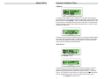
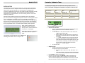
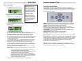
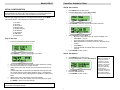
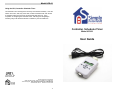
Model UCS-01 Using the UCS, Controller Scheduler-Timer The Scheduler-Timer is designed for accuracy and maximum flexibility. Once the UCS is set for time, date, day of the week, location and Network ID, then all that is needed is setting each event for the desired ON and OFF time. Upon completion of configuring the Scheduler-Timer, switching from ON [RUN] to vacation [VAC] mode should be all that is needed for years of reliable use. Controller, Scheduler-Timer Model UCS-01 User Guide Simply Automated, Incorporated 5825 Avenida Encinas, Suite 101, Carlsbad, CA 92008 USA Technical Support: www.simply-automated.com or 800-630-9234 452-0031-0101 Rev A Revised: June 22, 2006 12 Model UCS-01 Controller, Scheduler-Timer CIM Mode To configure the Scheduler-Timer to operate as a Computer Interface Module (CIM), allowing a PC with Upstart to access a UPB network, select the CIM mode from the menu and press ENTER button to initiate CIM mode operation. Note the unit will not run scheduled events when in the CIM mode. During CIM mode operation pressing any button will end the CIM mode function. There is no timeout period for CIM mode. The UCS may now be used via the RS-232 port as a Computer Interface Module. The default mode is Message Mode. UPStart will put the UCS into Pulse Mode when connecting UPB Device Interface within UPStart. Exit and re-enter CIM mode to put the UCS back into Message Mode. Clock Source Press ENTER button. The Scheduler-Timer is synchronized by the 60hz power signal for maximum accuracy. Selecting N for NO synchronization sets the Scheduler-Timer to operate using the internal clock, which has a maximum error of + 1.7 seconds per day. For maximum accuracy select Y for YES to synchronize the SchedulerTimer to the 60hz power source. Press Up / Down to select Y(es) or N(o). Press ENTER button to save. 11 Model UCS-01 Controller, Scheduler-Timer OTHER MENU SELECTIONS DESCRIPTION Delete Events The UPB Controller, Scheduler-Timer (model UCS) provides control of UPB devices or UPB Links according to a user defined event or schedule. It is designed to communicate with a UPB network when connected to a standard power receptacle; using the L-shaped power connector or the 6 foot power cord, both included. A range of events can be deleted by entering the event range, for example from 5 to 10, then pressing ENTER , which would delete events 5 through 10. A single event may be deleted by specifying the range to be the same number (e.g. from 5 to 5, would delete event 5). Input the desired events to be deleted then press the ENTER button to delete the range of events. Set Randomness The UCS can offload scheduled events from a whole home automation system and provide quick and easy event scheduling for an end user. Up to 99 events can be configured once the time, date and location are set in the UCS. Location is set by entering zip code or latitude/longitude. The 99 available event(s) can control a device or a Link with respect to time, sunrise (dawn), sunset (dusk) or a combination of a time ± minutes from sunrise or sunset. Each event has a mode setting (Event Mode) which can be configured as ON (‘R’), OFF (‘r’) or ON with random time settings (‘V’) for vacation. The Schedule Modes ON [RUN], OFF [OFF] and vacation [VAC] allow the user to quickly change the operation of the Scheduler-Timer so the corresponding Event Modes occur. For example an event set for Event Mode ‘V’ only operates when the Schedule Mode is set for (VAC) vacation. The easy to navigate menus allow configuration without the use of a PC or software. The Scheduler-Timer is intended for use by an installer or homeowner who is familiar with the installed UPB Network and UPB products. Vacation Events are designed so that the ON and OFF time can be random, from plus or minus 1 to 60 minutes, so that the home has a ‘lived in’ look. As an example, if Vacation random is set to 10 minutes, and the Schedule Mode is set for [VAC] Vacation, then all events set for Event Mode ‘V’ will turn ON and/or OFF within plus or minus 10 minutes of the scheduled ON or OFF time. A new random number is applied to each of the Vacation Events every day and is the same random number for both ON and OFF time. In the CIM Mode the Scheduler-Timer may be used as a Computer Interface Module, allowing a PC with UPStart configuration software to connect to a UPB network through the UCS. Select the number of minutes then press ENTER button to save. 1. 2. Set Contrast IMPORTANT SAFETY INSTRUCTIONS When using electrical products, basic safety precautions should always be followed, including the following: 3. 4. 5. 6. 7. 8. To adjust the display contrast (i.e. viewing angle), hold the Up or Down button until the desired contrast is displayed. Press ENTER button to save contrast level. 9. 10 3 READ AND FOLLOW ALL SAFETY INSTRUCTIONS. Keep away from water. If product comes into contact with water or other liquid, unplug immediately. Never use products that have been dropped or damaged. Do not use this product outdoors. Do not use this product for other than its intended use. To avoid risk of fire, burns, personal injury and electric shock, install this product out of reach of small children. Do not cover the product with cloth, paper or any material when in use. This product uses polarized plugs and sockets (one blade is wider than the other) as a feature to reduce the risk of electric shock. These plugs and sockets fit only one way. If they do not fit, contact a qualified technician. Do not use with an extension cord unless plugs can be fully inserted. Do not alter or replace plugs. SAVE THESE INSTRUCTIONS. Model UCS-01 INSTALLATION The Scheduler-Timer is designed for indoor use. Simply plug the appropriate end of the power cord or L-shaped connector into the top of the UCS, and the other end into any 120-volt outlet. For convenience the L-shaped power connector is designed to hang the unit from a high (mid-wall) receptacle, typically found in the kitchen or garage. The 6 foot power cord can be used when programming as a hand-held device, or when mounting the unit in some other location (e.g. table top). Controller, Scheduler-Timer The following table details the Schedule Mode and Event Mode operation. Schedule Mode is displayed on the Idle Screen and adjusted from the Set Time screen. Event Mode is displayed and adjusted in the specific Set Event screen. When the memory battery back-up of the Scheduler-Timer is fully charged (24 hours of powered / charging time required to achieve a full charge) the device can be unplugged or un-powered for up to one week without losing time or events. This feature also makes programming and testing of room lighting easy since the user can power and program the unit in one location, then unplug the device to move it to another ‘plug-in’ location within the house without losing the time or programmed events. The UCS requires 120VAC power to operate. When power is provided to the Scheduler-Timer the unit runs a start-up routine, and then shows the ‘Idle Screen’ on the display. Schedule Mode: (as viewed on Idle Screen) Event Mode: Off mode = ‘r’ [OFF] Off Off Off [RUN] Off Run Off [VAC] Off Run Run with vacation randomness Set On Time / Off Time: o The Up / Down buttons scroll through the hours:minutes, AM / PM and deviations from Dusk and Dawn selections. o Examples: 07:00P 11:00P, where the event or Link turns on at 7PM and turns off at 11PM. Dusk+15 Dawn-30, where the event or Link turns on at Dusk plus 15 minutes and turns off at Dawn minus 30 minutes. ------ 11:00P, where the event or Link (only) turns off at 11PM. This function is used to make sure one or more devices are turned off at a specific time (e.g. all off command). Conversely, an event could be set to only turn ON by entering an ON time and then entering “------“ for the off time. o A = AM, P = PM. • Set Event Type: o The Up / Down buttons scroll through the dim levels D0 through D9, and LA for Link Activator. Dim levels: D0 = 100%, D9 = 90%, D8 = 80%... D1 = 10%. LA is Link Activator, where the device(s) receiving the Link control how they respond for dim Level and Rate. Press ENTER button to save Event Once the event is saved, press ENTER button to test Event On function and press ENTER button another time to test Event Off. The event must be displayed on the Scheduler-Timer screen to run the tests and a Device ID must be valid and stored for the specific event. The diagnostic LED should be lit with an AMBER color indicating the Scheduler-Timer is ready for use. • • 9 Event Mode: Vacation mode = ‘V’ • Idle Screen showing: time, Schedule ‘RUN’ Mode, date and day of the week. 4 Event Mode: Run mode = ‘R’ Model UCS-01 Controller, Scheduler-Timer Step D: Set Events Hint: Each Event in the FUNCTION / NAVIGATION Scheduler-Timer requires the Device ID of the UPB device or the Link ID of the UPB Link to be controlled. It is highly recommended that the user creates a list of Device ID and Link ID numbers correlating to the UPB devices to be controlled before setting up the events. This will prove useful when entering events since the list can be quickly referenced to tie the UPB device to the event. The Scheduler-Timer has an LCD display with 2 lines of 16 characters, a diagnostic LED, 7 buttons, a polarized power connector and a DB-9 serial port. The 7 buttons provide easy navigation through the menus on the LCD display and are described as follows: • Press MENU from the IDLE Screen. • Select Set Events and press ENTER button. • Or, from the IDLE Screen press the Up or Down button and scroll to an available event. • Use the Right / Left buttons to move the cursor across the screen and the Up / Down buttons to change the character at the cursor. The first two characters on the screen are the Event ID numbers. There are 99 Event ID numbers from which to choose, 01 to 99. We recommend selecting 01 as the first event, 02 as the second and so on, so that you can easily see how many events are used and know how many remain unused. The characters following the ‘)’ represent the Device ID of the device being controlled or the Link ID of a Link being controlled. Enter the Device ID or Link ID for the event using the Up / Down buttons. The next characters represent the days of the week. A capital letter turns the event ON for that day and lower case turns the event OFF for that day. Using the Up / Down buttons, enter the days of the week in which the event should be ON (capital) or OFF (lower case). The next character represents the Event Mode which can be R, V or r. o R = Event will operate in Schedule [Run] Mode and [VAC] vacation mode without random time settings. o V = Event will operate in the Schedule [VAC] Mode only, and Vacation random time settings will be applied. o r = Event is off. The event will not occur in either [RUN] or [VAC] Schedule Modes. This ‘r’ setting is used to temporarily turn off and event. For example if the user does not want an event to run when going on vacation. Select the desired Event Mode using the Up / Down buttons. • • • • • 8 MENU: Provides access to the main menu from the Idle Screen. It will also return the display to the previous menu or Idle Screen from any sub-menu by exiting the selection without saving the configuration data. ENTER: Enters and saves a selected setting or menu item. Provides movement through selected menu item’s editable fields, executes commands and edits that are sent to the selected device or network. UP and DOWN: Provide movement through the menus and toggle through characters when editing a selection. RIGHT and LEFT: Provide movement across the display. FUNCTION: Toggles the backlight on the LCD display. Diagnostic LED: The diagnostic LED operates just like the LED of a Computer Interface Module. In CIM Mode the Scheduler-Timer exchanges UPB messages between the powerline and the connected computer or controller. The indicator on the UCS will glow AMBER when powered, flash RED when UPB messages are seen on the power line and flash GREEN when a UPB message is transmitted from the Scheduler-Timer. DB9 Port: Connect a standard serial cable to an RS-232 port to use the Scheduler-Timer as a Computer Interface Module. The DB9 port may also be used to upgrade the firmware in the UCS, if needed. 5 Model UCS-01 Controller, Scheduler-Timer Step B: Set Location INITIAL CONFIGURATION NOTE: In order to completely configure the Scheduler-Timer it is necessary to know the Network ID, Device ID(s) and Link ID(s) to be controlled, writing down the Device ID for each UPB device to be scheduled is recommended. • • Press MENU from the Idle Screen. Press the Down button to select Set Location. • Press ENTER button to view the Set Location sub-menu. • Select Zip Code and press Enter . o Zip Code – Enter Zip by using Up / Down and Right / Left. o Press Enter to save. o Screen will toggle to Longitude & Latitude screen. o Make adjustments if necessary and known, otherwise do not change. With the UCS plugged into power on a configured UPB network, press MENU from the Idle Screen. The following menu selections are available: 1) Set Event 2) Set Time 3) Set Location 4) Delete Events 5) Set Randomness 6) Set Network 7) Set Contrast 8) CIM Mode 9) Clock Source Step A: Set Time • Press the Down button to select Set Time. Press Enter . UCS will calculate and display Dawn (sunrise) and Dusk (sunset). Press ENTER button to save. o o • Press ENTER button to view the Set Time screen. • • • • • • Step C: Set Network Move cursor with Right and Left buttons to select character to change. Use Up and Down buttons to change character. Adjust time by hours and minutes, Up or Down from character on the display. Use the Right button to select the Schedule Mode character, then use UP or Down buttons to select [OFF], [RUN] or [VAC]. The SchedulerTimer will be turned ON by selecting either run [RUN] or vacation [VAC] mode. Adjust month / day / year and day of the week, similarly. When the time, mode, date and day of the week have been set, press the ENTER button to save the settings. NOTE: Pressing the MENU button instead of the ENTER button will exit the screen without saving the settings. 6 7 • • Press MENU from the Idle Screen. Press the Down button to select Set Network. • • Press ENTER button . Enter the UPB Network ID. Press ENTER button to save. Hint: if the Network ID is unknown it will be necessary to run the UPStart configuration software or the Pocket Programmer (model UPP-20) to determine the Network ID. To find the Network ID in UPStart, from the top menu select Network, then Network Properties.