1
owners
manual
MODEL NO.
113.20680
Serial
Number
Model and serial
number may be found
on a plate attached
to your infeed table.
You should record both
model and serial number
CRRFTSMRNo
in a safe place for
future use.
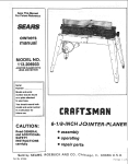
6_- INCH JOIN TER-PLA NER
CAUTION-.
Read GENERAL
and ADDITIONAL
SAFETY
. assembly
o operating
INSTRUCTIONS
carefully
Sold by SEARS,
Part No, 67018
e repair
ROEBUCK
AND
parts
CO.,
Chicago,
IL. 60684
U.SA.
FULL
ONE YEAR WARRANTY
ON CRAFTSMAN
JOINTER/PLANER
This warranty_giVes you specific legal rights; and you may :alsohave other rights which vary from state to state.
SEARS. ROEBUCK
AND
BSC 41-3
SEARS TOWE R
CHICAGO,
I L 60684
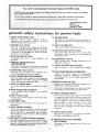
general
safety
instructions
KNOW YOUR POWE R TOOL
This
Learn
its
the specific
Use damps
safer
tool.
ALL TOOLS
tool
is equipped
an approved
3-conductor
in
working
15. MAINTAIN
Keep
and
in
proper
adjustment
habit
of checking
5. KEEP WORK
Cluttered
must
-6,
and
not be slippery
from
toot
benches
turning
it on.
invite
accidents.
should
5ekept
8. MAKE WORKSHOP
- with
padlocks,
starter keys.
work
"
:
for
best
for
and
safest
lubricating
and
changing
accessories
such
as
ACCIDENTAL
STARTING
is in "OFF"
position
before
plugging
KID-PROOF
master
switches,
or
by
Before
and safer at the rate for which
to do a job
contain
long
GOGGLES
hair.
Roll
it was not
long
PARTS
use of the tool,
a guard or other
part that
for alignment
: i
of moving
parts,
binding
of moving
parts,
breakage
conditions
that
of parts,
mounting,
and any other
may ,affect
its operation.
A guard or
other part that
or replaced,
is damaged
: Feed work
of rotation
(Head Protection)':
protectors:(piugs,or
muffS):
opel_atiort.= _:-:
:: ::
DAMAGED
further
21. DIRECTION
sleeves
og es (must corn I w th ANSZ87
1)at
A_so g Use::: face orP_tYust mask ill.cuffing:
operation
is duSty_i andear
duringextended:_HodsiOf
materials above or near the tool .such that
to stand on the toot to reach them.
is damaged should be carefully checked to ensure that it
will operate properly
and perform
its intended
function.
Check
or attachment
ON TOOL
removing
Do not wear loose clothing,
gloves, neckties or jewelry
(rings,
wrist
watches)
to get caught
in moving
parts;
Nonslip
footwear
is recommended.
Wear protective
hair covering
to
above the elbow,
Donor
store
iris necessary
20. CHECK
better
ACCESSORIES
in'ur
j y cou d occur f the too is ti pped or if the
too
s accidentally
contacted .
cutting
........
a Safe
11. WEAR PROPER APPAREL
:
Serious
. ,.
TOOL
Don't force tool
designed for,
Wear:Safety
ati times.
when
etc,
_:: : z19_:NEVER STAND
space.
FORCE TOOL
It will do the job
it was designed,
:
::
clean
Consult
the
owner's
manual
for
recommended
accessories.
Follow
the instructions
that accompany
the accessories.
The use of improper
accessories may
cause hazards,
,
: 12, USE SAFETY
at all times.
instructions
18. USE RECOMMENDED
Floor
area,
10. USE RIGHT
It's
TOOLS
Make sure switch
in.
ENVIRONMENT
Provide adequate surrounding
7
k'l=l=P r_l-lllr_Rl=l_i
_
....................
•-,WAY
9. DON'T
and
Follow
servicing;
17. AVOID
keys and adjusting
before
due to wax or sawdust,
DANGEROUS
visitors
practical.
hands to operate
blades,bits, cutters,
Don't use power tools
in damp or wet locations
or
expose
them
to _r_ain.: Keep, work area well lighted,
All
when
AREA CLEAN
areas
AVOID
KEYS
to see that
are removed
work
frees both
and balance
sharp
16. DISCONNECT
and
before
4. REMOVE ADJUSTING
AND WRENCHES
Form
hand.
accessories.
changing
alignment,
wrenches
your
TOOLS WITH CAR E
tools
performance.
IN PLACE
order,
or a vise to hold
than using
Keep proper footing
to a live terminal,
3. KEEP GUARDS
fools
14. DON'T OVERREACH
with
cord and a 3-prong grounding
type plug to fit the
proper grounding type receptacle. The green conductor
in the cord is the grounding wire. Never connect the
green wire
power
13. SECURE WORK
Read
the
owner's
manual
carefully,
application
and limitations
as well as
potential
hazards peculiar to this tool.
2. GROUND
for
CO.
•
:
22. NEVER
should
be properly
repaired
OF FEED
into a blade or cutter against
of the blade or cutter only.
LEAVE
TOOL
the direction
RUNNING
_: UNATTENDED
:
: Turn power off.
complete stop.
Don't
eave tool
until
t comes
to a
additionaB safety instructions for iointer-paaner
Safety
is a combination
of operator
common
sense and
alertness at all times when the Jointer-Ptaner
is being used.
9. PROTECTION:
a.
WARNING:
FOR YOUR OWN SAFETY, DO NOT ATTEMPT TO OPERATE YOUR JOINTER-PLANER
UNTIL
IT IS COMPLETELY
ASSEMBLED AND INSTALLED
ACCORDING TO THE INSTRUCTIONS,..
AND UNTIL
YOU HAVE READ AND UNDERSTOOD THE FOLLOWING,
GENERAL
SAFETY
INSTRUCTIONS
TOOLS
..............................
b.
FOR POWER
TO KNOW YOUR JOINTER-PLANER
3. BASIC MACHINE
5. MAINTENANCE
6. STABILITY
. . 12
OPERATION ..............
4. USE OF HOLD-DOWN/PUSH
FACE,
EARS,
If any part of your jointer is malfunctioning,
damaged or broken..,
such as the motor
BODY
has been
switch,
or
Wear safety goggles that comply
with
ANSZ87.
11968, and a face shield if operation
is dusty.
Wear
ear plugs or muffs during extended
periods of operation.
2
C,
2. GETTING
HANDS,
other operating
control,
a safety device or the power
cord
. . . cease operating
immediately
until
the
particular
part is properly
repaired or replaced.
PAG E
t.
EYES,
19
BLOCKS .........
ward you.
20
........................
Do not plane, joint, or bevel wood shorter than t2
in. Smaller
pieces of wood can tip over on the
tables, or into the cutterhead
and be kicked back to-
d_
Always use the hold down/push
block when jointing
or beveling wood narrower
than 3 in. but never joint
or bevel wood narrower
than 3/4 in. under any circumstances.
e.
Always use the hold down/push
blocks when
wood thinner
than 3 in. but never plane wood
than 1/2 in. under any circumstances.
f.
Avoid
could
22
OF MACHINE
If there is any tendency
for the Jointer-Planer
to tip
over or move during
certain
operations
such as when
planing
or jointing
long heavy
boards,
the JointerPlaner (stand) should be bolted to the floor,
awkward hand positions,
cause a hand to move
planing
thinner
where a sudden slip
into the cutters.
7. LOCATION
g.
The Jointer-Planer
should be positioned
so neither the
operator nor a casual observer is forced to stand in line
with the wood while it is being planed.
This machine
adequate
is intended
for
indoor
use only.
Provide
h_
lighting.
8. KICKBACKS
Kickbacks - and possible injury
avoided by:
Holding
the workpiece
firmly
from
them can usually
against tables
C.
1/16
of an inch
Not jointing,
planing,
or
smaller than recommended.
deep will
produce
be
GUARD
IN PLACE
AND
OPERAT-
Always feed the wood completely through the cutter
head and past the cutter guard so that the guard returns to the rest position
against the fence. When
using only one hold down/push
block
to feed the
wood, do not place your other hand on the JointerPlaner.
and fence.
10. Warped wood should be surface planed on the concave
side for best results.
the best
11. To avoid a rough planed surface, determine
if possible,
which
way the grain emerges from the wood and feed
the wood accordingly.
beveling
pieces of wood
(See section in this man-
ual,'BasicJointer-Planer
Operations.")
Smaller pieces
of wood can tip over on the tables, or into the cutter
head and can be kicked back toward you.
d.
CUTTER
ING PROPERLY
AT ALL
TIMES.
Regularly
check
the tension
of the cutter
guard spring to assure
satisfactory
operation.
(See Getting To Know Your
Jointer-Planer
section,}
b. Not taking too deep a cut at one time. A deep cut
requires
more effort to feed the wood while planing
and can cause the wood to kickback.
A cut between
1/32 and
results.
Make sure the cutterhead revolves in the right direction, (toward the infeed table).
KEEP
Kickbacks
can cause serious injury. A kickback
occurs
when the operator
looses control
of the workpiece
causing it to be kicked back toward him.
a,
Never turn your Jointer-Planer "ON" before clearing
the table(s) of all objects (tools, scraps of wood, etc.)
except for the workpiece and related feed or support
devicesfor the operation planned.
Keeping blades sharp. BIades that are dull or nicked
require
more effort
While planing and will tend to
pound the wood rather than cut it, which can cause
the wood to kickback.
A nicked blade will cut a rid-
_%"GRAIN EMERGtN/G
ge in your wood and cause the wood to ride up on the
outfeed
table,
Make sure the cutter
blades are installed properly,
and cutter
blade wedge screws are
tight.
12.
3
Do not plane edges of plywood,
composition
materials,
or wood that has glue on it or is painted or varnished.
Planing
these materials
will
dull
the blades quickiy.
additional safety instructions for a'ointer-pmaner
TO BECOME COMMONPLACE.
ALWAYS REMEMBER
THAT A CARELESS
FRACTION
OF A SECOND IS
SUFFICIENT TO INFLICT SEVERE INJURY.
depth wanted, then raise the table to the desired depth_
14_:When
feet
planing,
Iongi
jointing,
make
sure
or beveling
it
wood
is supported
over:four
at
table
(4)
17:
height.
Read and followthe
instructions
label on the cutter guard.
15.: Never leave the Jointer-Planer
work area with the power
on; before the Jointer-Planer
has come to a complete
stop, or without
removing
and storing the switch key.
Never operate the Jointer-Planer
on the
unused
shaft end
of
appearing
on the danger
DANGER
FOR YOUR
READ
16,
....
with protective
cover
the motor
removed.
AND
OWNERS
OWN
FOLLOW
MANUAL
SAFETY
SAFETY
BEFORE
INSTRUCTIONS
OPERATING
THIS
IN
MA-
CHINE.
WARNING:
THE 2" JOINTER-PLANER
PULLEY AND
THE 2-1/2"" MOTOR PULLEY FURNISHED
WILL RUN
THE CUTTER HEAD AT APPROXIMATELY
4300 RPM
WHEN USED WITH A 3450 RPM MOTOR. NEVER
SUBSTITUTE OTHER PULLEYS
TO INCREASE THIS
SPEED BECAUSE IT COULD BE DANGEROUS.
NEVER
TER
OPERATE
GUARD,
THIS
SLIDING
MACHINE
GUARD
WITH
THE
OR BELT
CUT-
GUARDS
REMOVED.
3.
NEVER
ER THAN
MAKE
1/16
4. ALWAYS
JOINTING
WARNING:
DO NOT ALLOW FAMILIARITY
(GAINED
FROM FREQUENT
USE OF YOUR JOINTER-PLANER)
J01NTING
USE
HOLD
MATERIAL
OR PLANING
OR PLANING
CUTS
DEEP-
INCH,
MATERIAL
DOWN/PUSH
NARROWER
THINNER
BLOCKS
FOR
THAN
3 iNCHES
THAN
3 INCHES.
The operation
of any power
tool can result in foreign
objects
being thrown
into the eyes, which
can result in
severe eye damage. Always
wear safety goggles complying
with ANSI
Z87.1 (shown on Package) before commencing
power tool operation.
Safety
retail or catalog stores.
Goggles
are available
at Sears
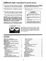
cOntents
POWER TOOL GUARANTEE.
...................
GENERAL SAFETY INSTRUCTIONS FOR
POWER TOOLS ..........................
ADDITIONAL
SAFETY INSTRUCTIONS
FOR
JOINTER-PLANER
........................
2
12
13
13
5
Cutterguard ............................
Infeed Table ...........................
On-Off Switch ..........................
BASIC JOINTER-PLANER
OPERATION
15
15
17
19
5
5
6
7
Feeding the Workpiece ....................
Using the Hold Down/Push Blocks ............
Beveling ..............................
MAINTENANCE
..........................
19
20
21
22
Replacing Cutter Blades....................
Installing Cutter Guard Spring ...............
Sharpening Cutter Blades ..................
GENERAL MAINTENANCE
..................
WIRING DIAGRAM ........................
LUBRICATION
..........................
TROUBLE SHOOTING ......................
RECOMMENDED
ACCESSORIES ..............
REPAIR PARTS .............
.............
22
24
25
26
26
26
27
27
28
2
3
MOTOR SPECl FICATtONS AND ELECTRICAL
REQUIREMENTS
.........................
Connecting to Power Source Outlet ............
Check Motor Rotation ....................
UNPACKING AND CHECKING CONTENTS .......
ASSEMBLY .............................
Mounting Jointer-Planer On Recommended
Craftsman Stand ........................
7
Checking Cutterblade Screws ................
Installing Sliding Guard ....................
Mounting Recommended Craftsman Motor and
Belt Guards ...........................
Check Motor Rotation. ....................
Jointer-Pulley Belt Guard Installation ...........
GETTING TO KNOW YOUR JOINTER-PLANER
Depth of Cut Handwheel ..................
Fence Locks and Stops ....................
Fence Tilt Scale .........................
7
8
8
9
....
11
12
4
.........
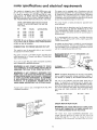
motor specifications and electrical requirements
]'his machine
is designed
to use a 3450 RPM motor only.
Do not use any motor that runs faster than 3450 RPM.
It is wired for operation
on 1t0-120
volts, 60 Hz,, alternating
current.
IT MUST
NOT
BE CONVERTED
TO
OPERATE
ON 230 VOI.TS.
EVEN
THOUGH
SOME OF
]-HE RECOMMENDED
MOTORS
ARE DUAL VOLTAGE.
THESE CRAFTSMAN
MOTORS
FOUND TO BE ACCEPTABLE
THIS TOOL.
HP
P.___M
R
VOLTS
1/2
t/2
3/4
3/4
3450
3450
3450
3450
110-120
110-120
1t0-120
t10-120
HAVE BEEN
FOR USE ON
CATALOG
NO.
12t6
1218
1219
1226
TO POWER SOURCE
This machine
must
be grounded
the operator from electric shock.
while
OUTLET
in use to
Plug power cord into a 1 t0-120V
properly
outlet protected
by a 15-amp. time delay
fuse or circuit breaker.
This plug
requires
outlet as shown.
a mating
3-conductor
grounded
as shown
ground.
and always
It is recommended
that
replace the TWO prong
THREE
prong outlet.
connect
the
grounding
you have a qualified
outlet
with a properly
WARNING:
IF NOT PROPERLY
GROUNDED
THIS
POWER TOOL CAN INCUR THE POTENTIAL HAZARD
OF ELECTRICAL SHOCK, PARTICULARLY
WHEN USED
IN DAMP LOCATIONS IN PROXIMITY
TO PLUMBING.
IF AN ELECTRICAL SHOCK OCCURS THERE IS THE
POTENTIAL
OF A SECONDARY
HAZARD SUCH AS
YOUR HANDS CONTACTING THE CUTTING BLADE.
or cut, or damaged
in any way, have
MAKE SURE THIS IS
CONNECTED
TO A
KNOWN GROUND
GROUNDING
LUG
ADAPTER
3--PRONG
"-""-_.F._,/
2-PRONG
RECEPTACLE
PLUG
------'-_
NOTE: The adapter iltustrated
is for use only if you already
have a properly
grounded
2-prong
receptacle.
Adapter
is
not allowed
in Canada by the Canadian
Electrical
Code.
The use of any extension
cord will cause some loss of
power.
To keep this to a minimum
and to prevent
overheating and motor burn-out,
use the table below to determine the minimum
wire size (A.W.G.)
extension
cord. Use
only 3 wire extension
cords which have 3-prong grounding
type
plugs and 3-pole receptacles
which
accept the tools
plug.
Extension
3--PRONG
PLUG
CHECK
PROPERLY
GROUNDED
electrician
grounded
grounded,
WARNING:
DO NOT PERMIT FINGERS TO TOUCH
THE TERMINALS OF PLUGS WHEN INSTALLING
OR
REMOVING THE PLUG TO OR FROM THE OUTLET.
!f power cord is worn
it replaced immediately.
to
protect
grounded type
or Circuit-Saver
sure that your outlet is properly
by a qualified
electrician,
tug
An adapter as shown below is available for connecting
plugs
to 2-prong receptacles.
The green grounding
lug extending
from the adapter must be connected
to a permanent
ground
such as to a properly
grounded outlet box,
/
If you are not
have it checked
type
If the outlet you are planning to use for this power toot is
of the two prong type
DO NOT REMOVE
OR ALTER
THE
GROUNDING
PRONG
tN ANY MANNER.
Use an
adapter
known
CAUTION:
Do not use blower or washing machine motors
or any motor with an automatic
reset overload protector
as their use may be hazardous,
CONNECTING
This power tool is equipped
with a 3-conductor
cord and
grounding
type plug which has a grounding
prong, approved
by Underwriters'
Laboratories
and the Canadian Standards
Association.
The ground conductor
has a green jacket and
is attached to the tool housing at one end and to the ground
prong in the attachment
piug at the other end.
Cord
Length
Wire
Size
A.W.G.
Upto
100-
100
200
Ft.
Ft,
!4
12
200-
400
Ft.
8
MOTOR
ROTATION
WARNING:
FOR YOUR OWN SAFETY, MAKE SURE
PLUG IS NOT CONNECTED TO POWER SOURCE OUTLET WHEN CHANGING MOTOR ROTATION.
OUTLET.
GROUNDING
PRONG
The
motor
viewed from
must
rotate
COUNTERCLOCKWISE
when
the shaft end to which
you wit_ mount
the
pulley,
(See page
according
to the
9), if it does not, change the direction
instructions
furnished
with
the motor.
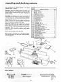
unpacking and
C
heckmg contents:
•
i ¸ .
•
•
•
••
•
Your: jointer:planer is ;shipped: complete in one carton
(_thou_: motor or Stand)_
Qty.
Separateatl parts from packing materials and check each
item ;with illustration and "*Tabie: of Loose Parts'. Make
certain all items are accounted for, before discarding any
packing material.
If any parts are missing, do not attempt to assemble the
jointer-ptaner, plug in thepower cord or turn the switch on
until the missing parts are obtained and installed correctly.
Using a 1/2 inch wrench, remove the wood attached to the
machine. Save the nuts, bolts and washers. You will need
them for attaching the machine to the stand.
Remove the protective 0il that is applied to all unpainted
metal surfaces. Be careful when cleaning the cutter head.
Use any ordinary household type grease and spot remover.
CAUTION:
Never use gasoline, na_ha or similar highly
volatile solvents.
Wipe all parts thoroughly with a clean cloth.
Apply
a coat of automobile
wax to the tables and fence.
This will help prevent rust and make it easier to feed the
work while planing.
1 : Jointer-Planer .......................
12 .i V:Belt, li2x 52". ....................
IV-Belt, 1/2 x 37", ....................
3
5/32 Setscrew Wrench ..................
4
1/8 Setscrew Wrench ...................
5
Motor Pulley, 2-1/2"' Dia ................
6
Sliding Guard Knob ...................
7
Concave Washer ......................
8
Sliding Guard .......................
9
Sliding Guard Rod ....................
10
Nut, 1/2- 13 ........................
11
Lockwasher, 1/2 .....................
12
Lockwasher, No. 10 ...................
13
Screw, Pan Hd., 10- 32 x !/4 .............
14
Owners Manual ......................
15
Depth of Cut Handwheel ................
16
Screw, Sims, 1/4 - 20 x 1-1/4 .............
17
Jointer-Ptaner Belt Guard ...............
18
Attaching Hardware (2 Nuts, 2 Bolts)
19
Motor Pulley Belt Guard ................
20
Belt Guard Clips .....................
21
Belt Guard Support Bracket ..............
22
Belt Guard Support ...................
23
2 self tapping screws
24
Switch Key .........................
t 25
Hold OownlPush Block ....
• • ..._..
1
!
1
1
1
1
1
2
1
1
1
1
2
2
1
1
1
t
1
3
1
1
.....
2
2
eSu pplied in Canada Only
3
5
4
1,,.
14
19
16
21
II
IIII
IIII
II
20
II
I
I
18
III
,
I,
11
t7
HI
IIIIIIIIIIII
I
I
"';
'":
'
, ......................................................
Square
••
:
:
; ::•:•:
:
:/:i/:
:
i'
%•
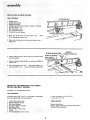
assembly
MOUNTING
JOINTER-PLANER
ON RECOMMENDED CRAFTSMAN STAND
(NOT
SUPPLIED
IN CANADA)
FENCE
See page 27 for recommended
PARTS
Nuts,
LOCK
KNOB
NEEDED
Bolts and Washers removed
1 - Round Hd. Mach.
Tooth Lockwasher
1 - Depth
TOOLS
1/2
stand.
of Cut
when unpacking
Screw t/4-20
attached
x 1-t/4
Jointer.
in. with
1-1/4
Ext.
IN.
SCREW
Handwheel
NEEDED
in. Wrench
Medium
Screwdriver
1, Loosen
FENCE
{t toward
LOCK
KNOB.Tilt
fence upward
and slide
the pulley.
2, Place the
mounting
machine
holes.
It _.,2"/
on
the
stand
as shown,
and
_
_
FLAT
WASHER
align
3. Place a fiat washer, a lock washer and a nut on each boff
from underneath
the stand and tighten.
NOTE:
The length of threads may vary on some bolts
and it may be necessary to add extra flat washers in order
to tighten the nuts securely,
4,
Place handwheel on shaft aligning
with flat surfaces on handwheel,.,
screw.
..... : .........................................
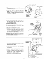
CHECKING
TOOLS
flat surfaces
attach with
on shaft
1-1/4 in.
i,,,
CUTTER
i i nl
BLADES AND SCREWS
i i.,
5/32 IN. SETSCREW
WRENCH
OUTFEED TABLE
NEEDED
5/32"
Jointer).
and
1/8"
Setscrew
Wrenches
(furnished
WEDGE
with
Lead Pencil
Short
straight
edge (or head of combination
1. Insert pencil
in space
cutterhead
guard open.
of
Cut
Rest the straight edge on edge on the surface of outfeed
table so it extends
across the opening
between
the
tables, at three
positions:
near each end and at the
middle of the cutter blade.
cutterhead
by
the
hold
3.
the
with
to
Lower
the
HandwheeL
Rotate
table
of cutterhead
2.
4,
infeed
at end
square)
grasping
the
Depth
2"
dia.
PENCI L
CUTTER
driven
GUARD
5. If a cutter blade adjustment
is not required,
check each
locking
screw of each wedge (5/32"
setscrew wrench)
and
tighten
if
necessary.
Hold
the pu{le¥
whiie
tightening
screws and be careful that your fingers do not
slip off the wrench."
pulley
and make sure each knife ticks
(touches)
the
straight
edge at all three
positions,
If not,
follow
procedure
under "REPLACING
CUTTER
BLADES"
on
ppg. 22 & 23.
7
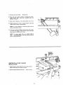
assembly
:= INSTALLING
PARTS
SLIDING
,: : i •:: i¸:•:I:
GUARD
NEEDED
1/2 IN. HEX NUT
1;
1:
1
2
1
1
2:
2
Sliding Guard
Sliding Guard Knob
Sliding Guard Rod
SlidingGuard Washers (one side of washer is concave)
Hex. Nut 1/2 in.- 13
Split Iockwasher 1/2 in.
EXt. tooth lockwashers
10-32x 1/4 Pan Hd. Screws
1. screw nut all the way onto long end of rod..,
1/2 in. lockwasher next to nut.
2. Screw rod all the way into Jointer
tighten nut.
with
short
SLIDING
place
end up...
SLIDING
10-32xl/4
3.
Attach
sliding guard
and Iockwashers.
to fence
4.
Place one Sliding
support rod.
5.
Drop sliding guard onto
cave side UP on rod..,
Guard
with
Washer,
PARTS
for
recommended
two machine
screws
concave side DOWN
GUARD KNOB
WASHER
(CONCAVE SIDE UP)
SCREWS
EXT. TOOTH
LOCKWASH ERS
on
rod..,
place other washer, conscrew on Sliding Guard Knob.
MOUNTING
RECOMMENDED
MOTOR AND BELT GUARDS
See page 5
GUARD ROD
CRAFTSMAN
motors.
NEEDED
4 carriage bolts, 5/16 - 18 x 1 in., flat washers, lock washers
and nuts supplied with Craftsman Stand.
2
2
Hex. Hd. Screws 1/4 -20x
Hex. Nuts 1/4- 20
1 Jointer Planer Belt Guard
1 Motor Pulley Belt Guard
I Belt Guard Support
1 BeltGuard Support Bracket
3 Belt Guard Clips
1 : Motor Pulleys,2-1/2 in; dia.
11 V-Bett:..
2 Pan Head S_rews 10 - 32 x 1/2 in. .........
TOOLS NEEDED
1/2 in.
Medium Screwdriver
5/32 in. Setscrew Wrench (furnished
1/2 and 7/16 in. Wrenches
'
8
with
Jointer)
5/8
IN.
DIA.
SHAFT
PAN HID. SCREWS
1. Place motor on your workbench
(with key way) facing you.
2. Attach
guard
support
to
with
bracket
5/8 in. dia. shaft
with
two
screws.
NOTE:
The holes in the bracket
are not threaded,
but
the screws are "thread
cutting
screws" and will cut a
thread as they are tightened.
BELT
GUARD
SUPPORT
BRACK ET
3,
Loosen setscrew in motor
shaft with hub flush with
shaft key and tighten
CHECK MOTOR
pulley
and place pulley
on
end of shaft, insert motor
DIRECTION
OF
ROTATION
setscrew.
5/32 IN,
SETSCREW
ROTATION
The
motor
must
route
viewed
from
PULLEY
1. Place motor
on your
BELT GUARD
SUPPORT
COUNTERCLOCKWISE
end.
workbench
WRENCH
when
\,
or on floor,
2. Stand
clear of motor
and plug cord into a properly
grounded
outlet (See page 5). Notice rotation
of pulley.
If it is not turning
COUNTERCLOCKWISE,
REMOVE
plug from outlet,
and change rotation
of motor according to instructions
furnished with motor.
WARNING:
FOR YOUR OWN SAFETY, MAKE SURE
PLUG IS NOT CONNECTED TO POWER SOURCE OUTLET WHEN CHANGING ROTATION.
FLUSH HERE
MOTOR
SHAFT
KEY
MOTOR MOUNT
BRACKET
1. Insert carriage bolts
behind motor mount
through
bracket.
holes marked
Loosen
4.
Loosen the two MOTOR
BASE CLAMP
SCREWS
rotate
the motor
so that
the ventilation
holes
facing downward..,
tighten the screws.
the BELT
BELT
GUARD
GUARD
SUPPORT
SUPPORT
GUARD
SCREWS
/
and a lock
but DON'T
3.
5. Tighten
two
from
BELT
2, Attach
motor
. . , place a flat
washer
washer on each bolt . . . screw on nuts
TIGHTEN
them.
the
"X"
SCREWS.
and
are
SCREWS.
.VENTILATION
HOLES
FACING
DOWNWARD
o
BASE
JCLAMP
(BOTH
9
SCREWS
ENOS_
_
assembly
BELT
6.
Install three clips on belt guard 90 ° apart with long tabs
pointing AWAY from round opening.
7. Insert belt into open end of guard.
/
_'_"BELT
GUARD CLIPS
(90 ° APART)
8. Snap guard into position as shown.
=
.
10
.
Remove
knob and washer..,
lift
guard up.
10, Place belt onto
Jointer pulley by rotating the pulley.
MAKE SURE BELT HAS NOT SLIPPED OFF OF
MOTOR PULLEY.
11. Move motor
sideways
12. PUSH downward
tighten
so that
on motor
nuts on motor
13,
to apply
mounting
NOTE:
It is only necessary
does not slip while running,
both
pulleys
are in line.
tension
to belt and
bolts.
to tension
the belt so that
it
If you cannot obtain sufficient
tension with motor pushed all the way down, remove the four motor
bolts and
insert them in LOWER set of holes.
NOTE:
To remove
guard, lift up on LONG
clips.
,. pull guard outward. The clips should
BELT GUARD SUPPORT.
TABS
remain
of
on
WASH ER
(CONCAVE
SIDE UP)
JOINTER-PULLEY
INSTALLATION
BELT GUARD
1. Attach guard to stand with Hex. Hd. screws and nuts,
Make sure belt does not scrape on guard.
2. Replace washer CONCAVE
side up...
screw on knob,
BOLT.
geffing
iointer-planer
WARNING:
FOR YOUR OWN SAFETY TURN SWITCH
"OFF" AND REMOVE PLUG FROM POWER SOURCE
OUTLET BEFORE MAKING ANY ADJUSTMENTS,
FENCE TILT
SCALE
(BEHIND
FENCE)
2
:FENCE
SLIDING
OUTFEED
FENCE
LOCK
KNOB
TABLE
GUARD
KNOB
1NFEED
TABLE
l
SLIDE
BRACKET
:
: ....
4
CUTTER GUARD
ON-OFF
SWITCH
DEPTH OF CUT
HANDWHEEL
INFEED
TABLE
UP
"I. DEPTH OF CUT HAN DW H EE L i _:
Turning the
handwheet counterclockwise will lower
table to maximum depthof:i/8
in.
DEPTH OF CUT
HANDWHEEL
the infeed
DOWN
12
FENCE
,
LOCKS AND STOPS. The fence can be
moved across the Jointer to take full
"sharpness"
of the blades.
The fence should be positioned
(toward
pultey) but not beyond
advantage
of the
to the extreme
right
the end of the blades.
Most of the cutting (usually jointing)
will be done with
the fence in this position, As the blades become dull,
the fence can be moved toward
the left where the
SLIDING
blades are sharper.
To move the fence, loosen the Fence Lock Knob and
the Sliding Guard
Knob and slide to desired position.
PUSH DOWN
WHEN LOCKING
FENCE LOCK KNOB
Make sure SLIDE
BRACKET
is even with surface
of
OUTFEED
TABLE.
If it is above or below the surface,
loosen
screws and adjust
it.
FENCE
a. Always tighten
fence lock knob first
then tighten sliding guard knob.
b. Before
down
C,
d,
tightening
on outfeed
fence lock knob,
hold
table so it does not
To
tables,
fence
at 90 ° to
f.
loosen
45 ° FENCE
STOP
fence
rock.
fence square to tables.
two knobs and pull the
angle and tighten
both
knobs,
tilt fence so the stop
place, Tilt
fence back so the
table and tighten
both knobs.
e,
to align fence,
90 ° Fence Stop positions
To tilt fence, loosen the
stop out. Tilt
to desired
knobs.
set
the
90 ° FENCE
STOP
two
FENCE LOCK
KNOB
springs back into
stop rests on the
SLIDE BRACKET
45 ° Fence Stop positions the fence at 45 ° to the
tables.
To
tilt
fence
to 45 °
90 ° stop out, tilt
table
g. Hold fence
two knobs.
GUARD KNOB
loosen the two
knobs,
pull
fence so the 45 ° stop rests on the
down
on outfeed
table and tighten
the
\/
FENCE
TI LT SCALE
90 ° FENCE'
STOP
=
FENCE TILT SCALE,
Indicates the angle of the
fence to the tables. When the 90 ° fence stop is correctly adjusted, the fence will be 90 ° to the table and
the scale wilt read 90 °.
To check for squareness,
infeed tabte and check
place
fence
position.
MAKE
SURE
SLIDE
BRACKET.
90 °
If fence is not square
a. Slightly
knob.
loosen
SQUARE
an accurate square on
while
locked
at 90 °
STOP
IS
FENCE
/
AGAINST
to table;
fence
lock
knob
and
guard
lock
13
CUTTER
GUARD
INFEED
TABLE
getting to know your iointer-planer
45 o ST
KNURLED
SLEEVE_.
I_oosen 90 ° stop screw with small screwdriver and
turn knurled sleeve which will cause fence to tilt.
Turn sleeve in either direction until fence is square
with infeed table;
b,
_:
_.
90 o. STOPS%
NOTE:
tf you
cannot square fence by turning
knurled
sleeve, loosen three screws "A'" and adjust
fence square to table.
Tighten
knobs.
C.
SCALE
ADJUSTING
90 ° stop Iockscrew and both fence lock
-
d_
_
SCREW
If 90 ° reading
on tilt scale does not line up with
top surface
of the slide bracket,
loosen screws
holding
scale and move
it...
tighten
screws.
-., , oc sc.Ew
::.;:t_l_
II
V_."'_ADJUSTING
SCREW
BRAC KE T
HEAD
OF
SQUARE
FENCE
e. Adjust
45 °
NOTE:
Tilt
was adjusted
.....
•
stop
in the
same
scale wilt not require
for 90 c position;
manner.
adjustment
if it
Ly:+-:
14
INFEED
TABLE
CUTTER
A
_'.
CUTTER
GUARD,
cutter head. it must
ing properly,
Check
per ly,
FENCE
the
guard
to
a, Position
fence
to right for maximum
make sure it is functioning
b. Pass a 1/4 in. thick
between
quard
Guard must return
against fence when
If guard
Shooting
GUARD
Provides
protection
over the
always be in place and function-
piece of wood
width
pro-
of cut.
over cutterhead
and fence,
automatically
to
free of the wood.
does not
return
and Maintenance
automatically,
Sections.
"rest
INFEED TABLE
position'"
see Trouble
CROWNED CUT
_.
INFEEDTABLE:MUST
LEL TO THE
OUTFEED
ALWAYS
TABLE.
BE
PARAL-
If the cut edge or surface
of the workpiece
is
CROWNED,
it is an indication that the OUTWARD
END of the INFEED
table is HIGH
and must be
adjusted.
,.FEED
TAB'E
If the cut edge or surface of the workpiece
is CONCAVE,
it is an indication
that the OUTWARD
END
of the INFEED
table is LOW and must be adjusted.
Check
parallel"
the
infeed
table
to
determine
the
"out
CONCAVE
END
HIGH
TABLE
LOW
CUT
of
condition.
INFEED
15
.getting toknow
your iointer-ploner
ROTATE
BLADE OUT OF
Insert a pencil in space at end of cutterhead to
hold cutterguard open.
b.
PENCIL
Place a straightedge (large square or long level) on
outfeed table. First along one side than along the
other.
c. Raise infeed table until it touches straightedge.
d.
Sight between table and straightedge to determine
high or low condition of end of infeed table.
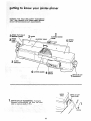
It is easier to adjust the infeed table while the Jointer is
setting on your workbench.
Do not turn the Jointer on its side or upside down to
adjust it.
i
Attach a stripof wood to two blocks of wood 10 in. high.
Drive enough
nails into the strip so that Jointer does
not tip over while resting on blocks.
a. Remove motor
cord from
outlet
t
t
in switch box,
10 IN,
b, Remove,joir_ter
:,
c.
:::
:::d, Lower theinfeed
:
:::e.
Remove Jointer from stand.
f.
table,
Place Jointe_ioh biocksill_
•.
....
pulley guard and V:belt ..........
....
.........
BLOCKS
: : OF WOOD
•_: :i _i_¸::I•:
:
"
YOUR WORK
BENCH
• ii!i___i _i, :_ii;_:_ i'=_i _L,,,:,,,,,,,,II,
I::?_
.i
Ill
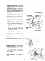
PENCIL
Insert a pencil in space at end of cutterhead to
hold cutterguard open,
g. Wrapa piece of cardboard aroUnd::cutterhead to
i protect your fingers and the blades : . . secure
:cardboard with a piece of tape.
,
i
i_i_i ii_i _i_i
_i _: i : i_!_ i _
i IL!_
_ii, :ii_i !i_;!
ii!;i_ i _
•16
CARDBOAR D"
h. Loosen
wrench.
four
lock screws
2 or 3 turns with
t/2
in.
v
VIEW LOOKING
Turning
the LEVELING
the infeed table.
STUDS
will RAISE
or LOWER
SCREWING in the studs will RAISE the table
UNSCREWING them will LOWER the table,
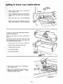
a. With
a 3/4
infeed
in. wrench
table is parallel
turn
with
UP FOR PARTS IDENTIFICATION
leveling
. , ,
studs
until
straightedge.
b. While holding
studs with wrench,
TIGHTEN
all
four LOCKSCREWS...
tighten each screw a little
bit
at a time
until
all four screws are tight.
c.
Recheck
with
straightedge
table is parallel
to outfeed
ill
6.
to make
table.
sure
infeed
"
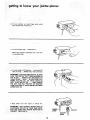
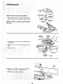
ON-OFF SWITCH:
It
is untikely
turned "ON"
accidentally,
when
because of the way it is shaped.
that
it will
be
touched
or bumped,
"OFF"
by striking
In an emergency,
it can be turned
it with the palm of the hand.
The "yellow
button"
is a key. When inserted in the
switch lever, the power may be turned ON and OFF.
When it is removed,
the power cannot be turned ON.
THtS
FEATURE
IS
INTENDED
UNAUTHORIZED
HAZARDOUS
AND
USE
BY
TO
PREVENT
POSSIBLE
CHILDREN
KEY
AND
OTHERS.
a. Insert
NOTE:
Key into switch.
Key is made of yellow
_
plastic.
17
geffng
to know
your iomter-pJoner
b;To turn machine on, insert finger under Switch
lever and pull end of switch out.
/
c. To turn machine OFF...
PUSH lever in.
Never leave machine unattended until it has come
to a complete stop.
d. To lock switch in OFF position .:.. hold switch IN
with one hand _;. =REMOV E key with other hand;
WARNI NG': FOR YOUR OWN SAFETY, ALWAYS
LOCK THE SWITCH "OFF"
WHEN MACHINE IS
NOT IN USE...
REMOVE KEY AND KEEPIT IN
A SAFE PLACE ... ALSO ... IN THE EVENT OF A
POWER FAILURE
(ALL OF YOUR LIGHTS GO
OUT) TURN SWITCH OFF,..
AND REMOVE
THE KEY. THIS WILL PREVENT THE MACHINE
FROM STARTING UP AGAIN WHEN THE POWER
COMES BACK ON.
e, Plug motor
cord
into
outlet
in switch
PULL
box.
WARNi NG: DON'T CONNECT POWER CORD TO
ELECTRICAL
OUTLET IN YOUR SHOP UNTIL
YOU ARE SURE THAT MOTOR ROTATION
IS
CORRECT.
(SEE PAGE 9h
OUTLET
CORD
CORD
18
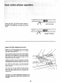
basic iointer-planer
operation
For your own safety, ALWAYS use the hold downtpush
blocks when JOINTING wood that is NARROWER than
3 in .... _)r when PLANING wood that is THINNER than
3in.
Do not
Material
plane, joint
this short
FEEDING
Hold the
AGAINST
or bevel wood
is more difficult
shorter than
to control
being
tables
cut. Small
or into the
pieces of
cutterhead
wood can tip over on the
and can be kicked back to-
ward you,
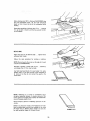
For best results, take light cuts. For average
jointing,
or beveling,
a cut between
1/32 and
deep wilt produce the best results.
t2 in,
while
planing,
1/16 in,
THE WORKPIECE
board
firmly
DOWN
on both
tables and
the fence . . . keep fingers close together,
Feed the board at a continuous
even rate of speed until
the cut is made along the entire length of the board. Any
hesitation
or stopping
could cause a "step"
to be cut
on the edge of the board which would cause the board
to ride up on the outfeed table resulting in a "crooked"
edge on the board.
As the
RIGHT
hand passes over
the cutterhead,
JOINTING
WOOD
THAT
IS WIDER
PLANING
WOOD
THAT
IS THICKER
THAN
3 IN.
remove
the LEFT
hand . , . CONTINUE
feeding while placing
the LEFT
hand behind the RIGHT.
Continue
feeding
in this
manner
"hand
over hand",
until
the entire
length
of the board
is cut.
DO NOT FEED TOO FAST. A slow steady rate of feed
produces
a smooth accurate cut, Feeding too fast causes
a "rippled"
cut . . . makes it difficult
to guide the
workpiece
accurately
and coutd be hazardous.
19
THAN
3 IN.
ic iointer-planer
operation
Always feed WITH THE GRAIN whenever possible. If
the nature of the workpiece is such that it must be fed
AGAINST THE GRAIN, take very light cuts and feed
slowly.
WITH THE GRAIN
AGAINST
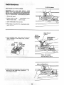
USING THE HOLD DOWN/PUSH
BLOCKS
/
ALWAYS use the holddown/push blocks when JOINTING wood that is NARROWER than 3 in. or planing
wood that is thinner than 3 in.
Grasp the hold down!push blocks firmly with the fingers
close together and wrapped around the handle. Position
them flat on top of workpiece, and push the workpiece
down against the table to provide a quality cut and
minimize the chance of a kickback.
Hold-down pressure must also be sufficient to prevent
hold-down/push block sliding or slipping on the top lace
of workpiece when advancing workpiece over cutter head,
Use a hand over hand motion of the hold down/push
blocks being careful to maintain control over the workpiece at all times.
This means that once the workpiece has been fed past
cutter head onto outfeed table, one hold down/push
block must always maintain contact of workpiece with
outfeed table.
CAUTION_
......
..........
BLOCKS tend to
If: the HOLD:DOWN/PUSH
slip while feedi_g_dean _ubber_surface immediately with
sandl_aper,
.... :
........
20:
THE
GRAIN
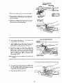
When planing wood 3/4 in. thick and NARROWER
than
the hold down!push
block,
ti]t the hold down/push
block
so that it clears the top of the cutterguard
while
feeding.
Never plane wood that is thinner than 1/2 in ....
because
it is apt to split or shatter and thus has a greater tendency to kickback.
BEVELING
Adjust
the fence to the desired
and guard lock knobs.
Follow
the
same
procedure
angle . , , tighten
for
jointing
or
fence
planing.
NOTE: Removing only the corner on the edge of a board
is known
as CHAMFERING.
Normally
a chamfer
is made with one cut..,
a cut deeper than 1/t6 in. may be made.
therefore,
Use hold down/push
blocks for wood under 3 in. wide.
Position them so you have control
of the workpiece
at
all times and so they do not contact
the guard or the
c_tter head.
CHAMFER
BEVEL
NOTE:
Rabbeting
on a Jointer
is considered
to be a
dangerous
operation
because it requires removal of the
cutter guard and increases the potential of kickback
because of excessive depth of cut.
Never attempt
Jointer.
Rabbet
to perform
cuts should
a rabbeting
be made on the
operation
Radial
on this
Saw or Table
Saw by making two cuts with the sawblade or by using
the Dado Head or Molding Head. Rabbet cuts can also
be made using the Shaper or Portable
Router.
RABBET
21
CUT
BROCK
OFWOOD
,,/
t: Remove belt guard.
:.........
_
2. POsitiOn fer_ce to right..,
approximately I/4
beyond cutter blades . , . lock it in=.place.
in.
3. Lower infeed table atl the way down.
4_ Place block of wood 6-3/4 in. long between cutterguard and fence.
HOLD PULLEY
FIRMLY
5. Hold cutterhead pulley firmly with one hand and
loosen lockscrews in each wedge using a 5/32 in,
setscrew wrench.
BLADE
LI FTER
SCREW
5/32 iN.
SETSCREW
WRENCH
TURN COUNTER
CLOCKWISE
WEDGE
LOCKSCREW
FENCE NOT SHOWN
FOR PICTURE CLARITY
I
1
SMALL SCREWDRIVER
6. While holding cutterhead pulley firmly with one hand,
gently pry up each wedge using a screwdriver..,
remove wedgesand blades.
r
7, Remove
the six lifter
screws.
(Two
under
each blade.)
CUTTER HEAD
SETSCREW
8. Clean cutterhead, wedges and screws thoroughly with
Craftsman
Gum and Pitch Remover. Also remove the
oil from new blades,
MARK SLOTS
9. Replace the six lifter screws and screw them in all the
way, but do not tighten. Mark each slot 1, 2, and 3.
This wilf help you in setting the blades,
1/8 IN. SETSCREW WRENCH
10,
Insert
a blade in slot marked
in, beyond
11.
1 ,..
so it projects
1/16
HEAD OF
SQUARE
end of the cutterhead,
\
"tnsert a wedge next to blade so the flat side of the
wedge is against the blade. Push wedge in manually
-do not install two locking setscrews at this time."
TABLE
t2.::_;Place head of square on outfeed table. Loosen lifter
screws to raise blade until it just touches square and
slightly
raises it. Gently
turn
cutter
head back and
forth with the pulley while raising blade. The blades
should be adjusted
just slightly above the outfeed
table,
by approximately
.003 in. (thickness
of an
average piece of paper},
LIFTER
NOTE: Sears has a knife setting gauge for this purpose. Cat.
# 9-2647
13. "Now install both locking setscrews and tighten (with
the 5/32" setscrew wrench) alternately a little at a
time. Tighten both screws securely, Recheck the blade
to make sure it did not change position,"
SCREW
f
14. Install other two blades the same way.
23
/
:
:I_ST_LLI:NG
::':::
:CUTTER
GUARD
SPRING::
:
guard
(located
underneath infeed
\
table.)
LOCK
.,..---SPRING
SPRING
_"-"
\
t, Remove €otter pin from pivot pin in cUttePguard:and
remove
!
FLAT WASHER
-_PLATE
/
WASHER"_.,
Spring must appear
in sketch from underside of inas
feed table, it will not perform properly if installed
upside down.
_
1
suPPORT
I
/
_'_
SCR EW
BUSHING
i
i
VIEW LOOKING
FENCE
IN PLACE
!,
UP
CUTTER
GUARD
1. Position guard as shown, with PIVOT PIN above hole
in infeed table.
2, Align SLOT in pin with TANG
down,
in spring, and press
3. Replace cotter pin:
_OL[_'
_INFEED
IN
TABLE
r
PIVOTPIN
.....
i
FENCE
LIFT
4. RAISE end of FENCE, rotate guard COUNTER
clockwise only enough to CLEAR fence,
5. LOWER fence and tighten: bothknobs.
:_OTATE
COUNTER
CLOCKWISE
:i:Y•::!ii•::•:
24
The normal position of guard (at REST) when fence is
stationed
at MAXIMUM
WIDTH
OF CUT, is shown as
"position
"A"
NEVER
ROTATE
GUARD
BEYOND
POSITION
"B'" BECAUSE THIS WOULD
EXERT
EXCESSIVE
TENSION
ON SPRING
WHICH
COULD
WEAKEN
OR BREAK
IT.
Check operation
of GUARD
and SPRING,
POSITION
"A'"
1. With fence in MAXIMUM
WtDTH
OF CUT position,
pass a piece of 1/4 in, thick wood on edge (jointing
position)
over cutterhead.
WIDTH
2. The guard should return automatically
position
against the fence when free
3,
CUT
to its REST
of the wood.
1
If guard does not return to its REST position,
remove
cotter pin from pivot pin and remove guard. Check
pivot pin and hole o.. make sure there are no burrs,
rust, or other foreign
matter.
4. Apply a few drops of SAE No. 20 or No. 30 engine
oil to pivot pin.
5, Replace
guard and cotter
pin.
If guard still does not return to its REST position,
consuit your
local Sears Retail
Store
before
using3 the
jointer-planer.
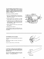
SHARPENING
CUTTER
BLADES
The blades can be honed
oilstone,
individually
with
Make sure your
must be flat,
is not
in the
Be sure to
oilstone
remove
the
burr
worn
on the
fiat
an ordinary
center.
It
side.
If the blades are nicked,
they must be replaced
or reground. They can be reground
several times until they
become 9/t6 in. wide. Never install reground blades less
than 9/16 in, wide.
Have your knives reground
petent. Look in the "Yellow
directory
...
see "Sharpening
8o
by someone who is comPages" of your telephone
Services".
11/16 IN.
NEW BLADE
25
OF
general: rna intenance
Keep your jointer-planer
clean. Put a carton or some kind
of a Container underneath
your jointer-planer
to Catch
the chips. The container should reach above the top of:
the motor.
E
Do not allow
pitch to accumulate
fence, the cutter guard, the cutter
Clean them with Craftsman
Gum
Do not allow chips to accumulate
jointer-planer.
Frequently
blow
side the motor.
on the tables, the
head or the knives.
and Pitch Remover.
For motor
with motor.
Apply a thin coat of automobile-type wax to the tables
and fence so that the wood slides easily while feeding.
out
on the underside
any dust that
maintenance,
follow
may accumulate
instructions
If power cord is worn or cut, or damaged
have it replaced immediately.
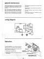
wiring: diagram
_
MOTOR
WHITE
_
OUTLET
L
I
11
_
SWITCH
_
Cap, Flag J
Terminal- I
/',,
E
m
m
m
m
lubrication
The BALL BEARINGS in this machine are packed with
greaseatthe factory. They require no further lubrication.
The following
parts should be oiled occasionally
SAE No. 20 or No. 30 engine oil.
1. Dovetail
spacer and dovetail
2 !. Elevating screw(first
Pitch RemoVer).
with
DOVETAi L
SPACER AND S LIDE
slide.
Clean: with
Craftsman
Gum
of the
and
,
VIEW LOOKING UP FOR
PARTS IDENTIFICATION
in-
furnished
in any way,
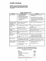
trouble shooting
WARNING: FOR YOUR OWN SAFETY, TURN SWITCH
"OFF" AND REMOVE PLUG FROM POWER SOURCE
OUTLET BEFORE TROUBLE SHOOTING YOUR JOINTER*PLANER.
TROUBLE
SHOOTING
CHART
,,J,_ _ ,J
TROUBLE
Motor
PROBi_BLE
will not run,
I,
Defective
Defective
REMEDY
your
i'.
On-Off switch,
switch cord.
Defective switch
2, Motor protector
motor
box receptacle.
open, (only if
is equipped
,,,i,,
,ll, ,,
Wood strikes outfeed
2. Consult
table after passing over
cutter head.
Ripples on planed
surface.
Feeding wood
ii i
..=l.l,,
Planed surface not
i,
i
I "' ""1 '
Re-adjust
than other,
too fast.
i,
i
i
blades, see Maintenance
t.
Re-adjust
section.
2.
Feed wood
.................................
Infeed table out of adjustment.
Excessivegougingat end Blades set too high above outfeed
of cut.
table.
blades,
1, Fence stops not adjusted
properly.
slower.
i
Infeed
i
i
table loose.
Cutter guard does not
function
properly.
u.i ,H. IH...
I
not even with
II
. I .HH..I
I
H
I IL
[
Hl,.i
i,
To
Know
section.
i
stops,
Jointer
see Getting
Jointer
i,lll,
,
To
PJaner section,
slide bracket,
your
,i,
.
fence
your
Re-adjust
2.
Know
I
,
1. Re-adjust
Know
Fence slide bracket
at your
see Maintenance
Reset blades, see Maintenance
table.
,, LI i
service
H ii
1,,,,,,uu,w
2.
to
section,
Re-adjust infeed table, see Getting
your Jointer
Planer section.
straight.
90° and 45 ° cuts
inaccurate.
Any attempt
may create a HAZARD
I1
adjusted below
table.
1. One blade set higher
2.
i
Sears Service.
repair this motor
using
technician.
Repair service is available
nearest Sears Store.
III I I
Blades improperly
I surface of outfeed
parts before
unless repair is done by a qualified
J"L''_J_'L"LLJ
....
,
Replace defective
machine again.
with an
overload protector).
Other cause
i,,,i, i
J, ,,,J,,
CAUSE
,J,ll,u
see Getting
To
Planer section.
,
t. Dovetail spacer requires adjustment.
2. Female dovetail
loose from table.
1. Tighten screw, key 10, see fig. 2, Parts List.
2. Tighten screws, key 18, see fig. 2, Parts List.
1. Return spring broken,
has been weakened.
1. Replace spring
or spring
Maintenance
immediately.
section,
2. See Maintenance
2. Improper assembly of spring or
guard mounting.
section,
IN CANADA, SEE YOUR LOCAL SIMPSONS-SEARS STORE
OR CATALOG FOR ACCESSORY SELECTION AND NUMBERS
RECOMMENDED
ACCESSORIES
ITEM
Floor Stand
.............................
Cutter Blades
............................
Power Tool Know-how
Handbooks
Radial Saw ........................
Table Saw .............................
Knife
Setting
The above
available
Gauge
CAT.NO.
9-22216
9-2293
9-29t7
9-29!8
.......................
recommended
at the time this
accessories
manual
27
9-2647
are current
was printed.
and were
See
CRAFTSM
AN 6-1/8 1NCH JOINTER-PLAN
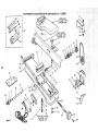
E R MODE L NO. 113.20680
12
INFEED TABLE
SEE FIGURE 2 FOR
EXPLODED VIEW
49
--47
FENCE ASSEMBLY
2 SEE FIGURE 3 FOR
EXPLODED VIEW
....-3
11
10
9
5
I
47
\
t
i
46
30
17
31
43
12
33
34
/
42
/
21
5
7
53
::S
36
37
SWITCH
FigureI
BOX
ASSEMBLY
SEE FIGURE 4 FOR
EXPLODED VIEW
26
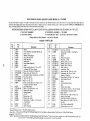
CRAFTSMAN
6-1/8 INCH JOINTER-PLANER
All parts illustrated
in Figures 1 through 4 and listed under
mall from the Cataleg Order House that serves the territory
parts are shipped prepaid within
the limits of the Continental
PART
GIVE THE FOLLOWING
INFORMATION
AS SHOWN ON THiS
3. THE MODEL NUMBER - 113.20680
NAME
4. THE
Always order by Part Number FIGURE
Part
No.
Key
No.
_o
1
2
3
4
5
6
7
8
9
10
11
12
!3
t4
15
.,
21013
Fence Assembly,
Knob, 1 -t/2
67020
21622
,.:::,,
Complete
Washer, Sliding Guard
Ring, Retaining 5/8
Ring, Retaining
Bearing 8all
Ring, Bowed Retaining
Spacer
Pulley with Set Screw, 2"
37158
18441
3509
38879
60345
62023
16
17
18
19
20
21
22
23
24
60252
STD 601105
,60253
60254
60255
37887
60096
455872
25
26
63410
,
. ,
Item
(See Fig. 2)
Dia. x 1/2"
V-Groove,
5/8" Bore, Keyed
*Screw, Set, 5/I6-8
x 5/t 6, Soc. Hd.
*Screw, Hex. Hd. I/4-20 x 1/2
Belt Guard, Pulley includes Key no.s12&14
*Nut, Hex. I/4-20
Belt, "V"
1/2 x 52
oBelt, "'V'" 1/2 x 37
tPulley with Set Screw, 2-1/2 Dia. x 1/2"
V-Groove,
5/8" Bore, Keyed
Guard-Belt,
Motor
*Screw, Ty 23 Pan 10-32 x t/2"
Support-Belt
Guard
Bracket-Support
Clip "'S"
*Wrench Hex., I/8
*Wrench Hex,, 5/32
Screw Much.,
w/Lockwasher
Knob,
Shaft,
67016
Hardware
........
Washer
STD 503103
STD 522505
67008
STD 541025
STD 304520
STD 304370
30646
"Standard
L
1/4-20
x 1-!/4
3-1/4
Elevating
-- May Be Purchased
NAME
Truss Hd.
OF
ITEM
-- 6-1/8
INCH
LIST:
JOINTER-PLANER
not by Key Number
1 PARTS LIST
Key
No.
Description
"18437
No, 113.20680
part numbers may be ordered through any Sears Retail Store or Catalog Order House. Order parts by
in which you llve. In several instances, part numbers are listed for COMPLETE
ASSEMBLIES.
Al!
United States.
WHEN ORDERING REPAIR PARTS, ALWAYS
1. THE PART NUMBER
2. THE
MODEL
Part
No.
27
28
Description
...................
'STD 54103i ...... *Nut, Hex., 5/16-18
102832
Screw; Set, 5/16-18 x 1 Ful! Dog Pt.,
29
30
31
32
33
34
35
36
37
38
39
40
4t
42
43
44
45
46
47
48
49
50
51
52
67017
21638
120238
STD 551150
STD 551125
STD 551025
18516
STD 551131
STD 523117
STD 551210
21733
60078
STD 580025
21636
67019
67021
21237
132275
2145O
18112
60116
21632
60117
60118
53
37159
67018
:::,
Slotted
Sleeve
Hd.
Rod, Sliding Guard
*Nut, Hex., 1/2-13
*Washer, Split Lock,
1/2
*Washer,Split Lock, 1/4
*Washer, Plain, 17/64 I.D.
Stud, Leveling
Lockwasher,
5/16
Screw, Hex. Hd., 5/16-t8
x 1-3/4
*Lockwasher,
No. 10 Int. Tooth
Support - Guard Pin
*Screw, Mach., 5/1648
x 1/2", Hex. Hd.
Key, Woodruff,
No. 9
Arbor
Push Block/Hold
Down
Base
Bracket, Fence Slide
Screw, Mach., 1/4-20 x 1, Fit. Hd. Slotted
Head Assembly,
Complete Cutter
tBtade, Cutter
*Screw, Cap. No. 10-32 x 3/4 Soc. Hd.
Wedge, Cutter Blade
*Screw, Set, 5/16-24 x 7/8 Soc. Hd.
*Screw, Mach., No. 10-32 x 1/2, Flat.
Soc. Hd.
Ring, Retaining
Owners Manual
Bowed 5/8
(not iltus.)
Locally.
f Stock Item -- May be secured through the Hardware Department
of most Sears or Simpsons-Sears
Retail Stores or Catalog Order Houses,
oSupplied
In Canada Only
NOTE : Shipping and handling charges for standard hardware items (tdenti fled by *) such as nuts, screws, washers, etc., make buying these items by mail
uneconomical.
To avoid shipping and handling charges, you may obtain most of these locally.
,,,,,,,,,
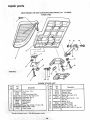
repair
parts
CRAFTSMAN
/
1
\
6-1/8 INCH JOINTER-PLANER
INFEEDTABLE
MODEL No. 113.20680
\
21
/
23
\
/
\
\,
2
22
20
\
6
FIGURE2
13
5
/
12
10
4
FIGURE
Key
No.J
1
2
3
4
5
: 6
7
11
2 PARTS LIST
Part
Description
No.
STD561210
67015
67014
STD511107
STD551210
STD551010
Pin, Cotter, 1/8 × 1
Guard
Table (with Name Plate)
Screw Pan Hd. 10-32 x 7/8
Lockwasher No. 10
t Washer, No. 10
No:,
13
14
15
16
17
18
I
19
20
2t
22
23
Standard Hardware-ltems_
M_y;B:e:PUtchasedI_o_lly_
Part
No.
21422
21219
21218
STD551131
21635
STD523t t2
Description
Spacer, Dovetail
Dovetail, Male
Dovetail, Female
"Washer, Split Lock, 5/16
Screw, SpI.
!_Screw, Cap, 5/16-18 x 1-1/4
Hex. Hd.
STD55103 t Washer, 5/16
21204
Linkage Assembly
STD541025
*Nut, Hex., 1/4-20
STD551125
*Washer, Split Lock, 1/4
*Screw, Cap, 1/4:20 x 1, Hex. Hal.
STD522510
/
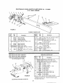
CRAFTSMAN
6-1/8 INCH JOINTER-PLANER
21013
2
3
4
5
6
MODEL
No.
113.20680
FENCE ASSEMBLY
7
10
11
12
17
16
15
FIGURE
3
FIGURE
Key
No.
1
2
3
Part
No.
3 PARTS LIST
Description
21013
21440
21430
STD 522512
21232
4
21736
5
6 STD551010
7 STD510802
102817
Fence Assembly
Plunger Assembly
Pin Assembly, Stop
*Screw, Hex Hd., t/4-20 x 1-1/4,
Plate, Fence End
Scale, Fence Tilt
*Washer, Plain, 13/64
*Screw, Mach., No. 8-32 x 1/4, Bind
Hd., Slotted
Screw, Set, 1/4-20 x 1/2", Full Dog
,i i, ii
i
i
Part
No.
9
10
11
21229
STD551210
STD511 t02
12
t3
67009
STD 533725
14
15
t6
21738
STD551037
47624
62331
t7
Pt.,Slotted
....................
i
Key
No,
i i i
i, ,,,,,,,,,,,,,,,,
,i i
i
Key
No. _
.Above assemblies do not include Key
No. 10. Order separately if needed.
1
2
3
4
5
6
7
8
9
1\
12
\
\
4
10
11
12
13
F1GURE 4
SEE WIRING
Spacer
Knob Assembty, Lock
, ,, .......
.......................
DIAGRAM ON PAGE 30
31
*Standard
Hardware
eCanadian
Models
iii!1
i ,iii,
4 PARTS LIST
Part
No.
STD54t110
STD551210
STD601103
60269
62376
60267
60317
60271
37818
=67023
60256
60287
=STD510603
60316
s67022
63467
,,,,,,,,,
i
Description
ii
1 2
\
Retainer, Bolt
Washer 35/64 I.D.
FIGURE
67025 SWITCH BOX ASM. (CANADIAN)
11
Body, Fence Incr. Key No's. 10 & 1t
*Washer, Lock, Ext. Tooth
*Screw, Mach., No. 10-32 x 1/4,
Pan Hd., Slotted
Guard, Cutter
*Bolt, Carriage, 3/8-16 x 2-t/2
Round Head
,,
67024 SWITCH BOX ASM. (DOMESTIC)
NOTE:
Description
i,
*Nut Hex. 10-32 x 3/8 x 1/8
*Lockwasher, No. 10 int. Tooth
*Screw, Ty 23, 10-32 x 3/8 Pan Hd.
Bracket, Housing
Outlet
Switch, Locking
*Washer, 21/32 x 1 x 1/64
Cord With Plug
Relief, Strain
Relief, Strain
Key, Switch
Screw, Nylon, 6_32 x 1/4
Screw, Pan Hd, 6-32 x 3/8
Box, Switch
Box, Switch
Cap, Flag Terminal, _nsulated
Item - May Be Purchased
Only
Locally.
iml,ll
,
i!ll
Sears:l
6-1/8
SERVICE
raNCH JOINTER-PLANER
Now that you have purchased your jointer-ptaner, should a need
ever exist for repair parts or service, simply contact
any
Sears Service Center and most Sears, Roebuck and Co. stores.
Be sure to provide all pertinent facts when you call or visit.
MODEL NO.
113.20680
The model number of your 6-1/8 inch jointer-planer
found on a plate attached to your infeed table.
HOW TO ORDER
REPAIR PARTS
WHEN ORDERING
REPAIR
FOLLOWING
INFORMATION:
PARTS,
ALWAYS
will
GIVE
be
THE
PART NUMBER
PART DESCRIPTION
MODEL NUMBER
113.20680
NAME OF ITEM
6-1/8 INCH JOINTER-PLANER
All parts listed may be
and most Sears stores.
locally, your order wilt
Repair Parts Distribution
ordered from any Sears Service Center
If the parts you need are not stocked
be electronically
transmitted
to a Sears
Center for handling.
i
Sold by SEARS,
Part No. 67018
ROEBUCK
AND
Form No.
CO., Chicago,
SP4064-7
IL. 60684
Printed
U.S.A.
in U.S.A.
1/78