1
Basic Home Station VDSL2
P8701T
Wireless N VDSL2 GW with USB
Default Login Details
LAN IP Address
http://192.168.1.1
Username/Password
1234 / 1234
Version 1.00
Edition 1, 11/2012
www.zyxel.com
www.zyxel.com
Copyright © 2012
ZyXEL Communications Corporation
IMPORTANT!
READ CAREFULLY BEFORE USE.
KEEP THIS GUIDE FOR FUTURE REFERENCE.
Note: This guide is a reference for a series of products. Therefore some features or
options in this guide may not be available in your product.
Graphics in this book may differ slightly from the product due to differences in operating systems,
operating system versions, or if you installed updated software for your device. Every effort has
been made to ensure that the information in this manual is accurate.
Related Documentation
• Quick Start Guide
The Quick Start Guide helps you get up and running right away. It contains information on setting
up your network and configuring for Internet access.
2
Basic Home Station VDSL2 P8701T User’s Guide
Table of Contents
Table of Contents
Part I: User’s Guide ......................................................................................... 11
Chapter 1
Introducing the VDSL Router ............................................................................................................13
1.1 Overview ...........................................................................................................................................13
1.2 How to Manage the VDSL Router .....................................................................................................13
1.3 Good Habits for Managing the VDSL Router ....................................................................................13
1.4 LEDs (Lights) ....................................................................................................................................13
1.5 The RESET Button ............................................................................................................................15
1.6 Wireless Access ................................................................................................................................15
1.6.1 Using the Wifi Button ...............................................................................................................16
1.7 Wall-mounting Instructions ................................................................................................................17
Chapter 2
User Setup Guide................................................................................................................................19
2.1 Access the VDSL Router Configuration ............................................................................................19
2.2 Changing the Configuration Password ..............................................................................................20
2.3 Setting Up a 3G Backup Internet Connection ...................................................................................21
2.4 Setting Your DSL Account’s Username and Password .....................................................................22
2.5 Setting Up a Secure Wireless Network .............................................................................................22
2.5.1 Configuring the Wireless Network Settings .............................................................................23
2.5.2 Using WPS ..............................................................................................................................24
2.5.3 Without WPS ...........................................................................................................................27
2.6 Using Wireless MAC Authentication to Block a Computer’s Access to the Wireless Network ..........29
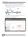
2.7 Setting Up a NAT Virtual Server for a Game Server .........................................................................30
2.8 Access Your Home Computer from the Internet Using DDNS ..........................................................32
2.8.1 Registering a DDNS Account on www.dyndns.org ..................................................................32
2.8.2 Configuring DDNS on Your VDSL Router ................................................................................33
2.8.3 Configuring Port Forwarding on your VDSL Router ................................................................33
2.8.4 Testing the DDNS Setting ........................................................................................................34
2.9 Configuring the Firewall ....................................................................................................................35
2.9.1 Interface Default Policy ............................................................................................................35
2.9.2 Firewall Rules ..........................................................................................................................35
2.10 LAN DHCP for IP Addressing Assignment ......................................................................................37
2.10.1 Configuring Static DHCP .......................................................................................................38
2.11 Checking the Software Version .......................................................................................................39
2.12 Restoring to Factory Default ...........................................................................................................40
2.13 How to Use File Sharing on the VDSL Router ................................................................................41
Basic Home Station VDSL2 P8701T User’s Guide
3
Table of Contents
2.13.1 Set Up File Sharing ...............................................................................................................41
2.13.2 Access Your Shared Files From a Computer ........................................................................43
2.14 Using the Media Server Feature ....................................................................................................44
2.14.1 Configuring the VDSL Router ................................................................................................44
2.14.2 Using Windows Media Player ................................................................................................44
2.14.3 Using a Digital Media Adapter ...............................................................................................47
2.15 How to Share a USB Printer via Your VDSL Router .......................................................................48
2.15.1 Add a New Printer Using Windows ........................................................................................49
2.15.2 Add a New Printer Using Macintosh OS X ............................................................................53
Part II: Technical Reference............................................................................ 59
Chapter 3
Device Info Screens............................................................................................................................61
3.1 Overview ...........................................................................................................................................61
3.2 The Device Info Summary Screen ....................................................................................................61
3.3 The WAN Info Screen .......................................................................................................................62
3.4 The 3G Status Screen .......................................................................................................................63
3.5 The LAN Statistics Screen ................................................................................................................65
3.6 The WAN Statistics Screen ...............................................................................................................65
3.7 The xTM Statistics Screen ................................................................................................................66
3.8 The xDSL Statistics Screen ...............................................................................................................67
3.8.1 The ADSL BER Test Screen ....................................................................................................70
3.9 The Route Info Screen ......................................................................................................................70
3.10 The ARP Info Screen ......................................................................................................................71
3.11 The DHCP Leases Screen ..............................................................................................................72
Chapter 4
WAN .....................................................................................................................................................73
4.1 Overview ...........................................................................................................................................73
4.1.1 What You Can Do in this Chapter ............................................................................................73
4.1.2 What You Need to Know ..........................................................................................................74
4.1.3 Before You Begin .....................................................................................................................76
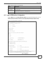
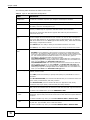
4.2 The Layer-2 Interface ATM Screen ...................................................................................................76
4.2.1 Layer-2 ATM Interface Configuration .......................................................................................77
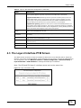
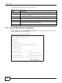
4.3 The Layer-2 Interface PTM Screen ...................................................................................................79
4.3.1 Layer-2 PTM Interface Configuration ......................................................................................80
4.4 The WAN Service Screen .................................................................................................................81
4.4.1 WAN Connection Configuration ...............................................................................................83
4.5 The 3G Backup Screen .....................................................................................................................95
4.6 Technical Reference ..........................................................................................................................97
4
Basic Home Station VDSL2 P8701T User’s Guide
Table of Contents
Chapter 5
LAN Setup .........................................................................................................................................103
5.1 Overview .........................................................................................................................................103
5.1.1 What You Can Do in this Chapter ..........................................................................................103
5.1.2 What You Need To Know .......................................................................................................104
5.1.3 Before You Begin ...................................................................................................................104
5.2 The LAN Setup Screen ...................................................................................................................104
5.2.1 Add DHCP Static IP Lease Screen ........................................................................................106
5.3 The IPv6 LAN Auto Configuration Screen .......................................................................................107
5.4 Technical Reference ........................................................................................................................109
5.4.1 LANs, WANs and the VDSL Router ....................................................................................... 110
5.4.2 DHCP Setup .......................................................................................................................... 110
5.4.3 DNS Server Addresses ......................................................................................................... 110
5.4.4 LAN TCP/IP ........................................................................................................................... 111
Chapter 6
Network Address Translation (NAT)................................................................................................ 113
6.1 Overview ........................................................................................................................................ 113
6.1.1 What You Can Do in this Chapter .......................................................................................... 113
6.2 What You Need to Know ................................................................................................................. 113
6.3 The Virtual Servers Screen ............................................................................................................. 113
6.3.1 The Virtual Servers Add Screen ........................................................................................... 114
6.4 The DMZ Host Screen .................................................................................................................... 116
6.5 Technical Reference ........................................................................................................................ 117
Chapter 7
Firewall .............................................................................................................................................. 119
7.1 Overview ........................................................................................................................................ 119
7.1.1 What You Can Do in this Chapter .......................................................................................... 119
7.2 The Firewall General Screen ......................................................................................................... 119
7.2.1 Default Policy Configuration ..................................................................................................120
7.3 The Firewall Rules Screen ..............................................................................................................121
7.3.1 Firewall Rules Configuration ................................................................................................123
Chapter 8
Quality of Service (QoS)...................................................................................................................125
8.1 Overview ........................................................................................................................................125
8.1.1 What You Can Do in this Chapter ..........................................................................................125
8.2 What You Need to Know .................................................................................................................125
8.3 The QoS Screen ............................................................................................................................127
8.4 The QoS Queue Setup Screen .......................................................................................................127
8.4.1 Adding a QoS Queue ...........................................................................................................129
8.5 The QoS Classification Setup Screen .............................................................................................130
Basic Home Station VDSL2 P8701T User’s Guide
5
Table of Contents
8.5.1 Add QoS Classification Rule ................................................................................................131
8.6 Technical Reference ........................................................................................................................134
Chapter 9
Routing ..............................................................................................................................................137
9.1 Overview ........................................................................................................................................137
9.1.1 What You Can Do in this Chapter ..........................................................................................137
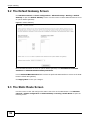
9.2 The Default Gateway Screen ..........................................................................................................138
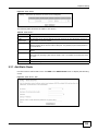
9.3 The Static Route Screen .................................................................................................................138
9.3.1 Add Static Route ....................................................................................................................139
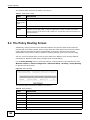
9.4 The Policy Routing Screen ..............................................................................................................140
9.4.1 Add Policy Routing ................................................................................................................141
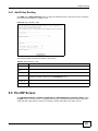
9.5 The RIP Screen ...............................................................................................................................141
Chapter 10
DNS Setup .........................................................................................................................................143
10.1 Overview .......................................................................................................................................143
10.1.1 What You Can Do in this Chapter ........................................................................................143
10.1.2 What You Need To Know .....................................................................................................144
10.2 The DNS Server Screen ...............................................................................................................144
10.3 The Dynamic DNS Screen ............................................................................................................145
10.3.1 The Dynamic DNS Add Screen ...........................................................................................146
Chapter 11
UPnP ..................................................................................................................................................149
11.1 Overview .......................................................................................................................................149
11.1.1 What You Can Do in this Chapter ........................................................................................149
11.1.2 What You Need To Know .....................................................................................................149
11.2 The UPnP Screen .........................................................................................................................150
11.3 Installing UPnP in Windows XP Example ......................................................................................150
11.4 Using UPnP in Windows XP Example ...........................................................................................152
Chapter 12
USB Services ....................................................................................................................................159
12.1 Overview .......................................................................................................................................159
12.1.1 What You Can Do in this Chapter ........................................................................................159
12.1.2 What You Need To Know .....................................................................................................159
12.2 The File Sharing Screen ...............................................................................................................160
12.2.1 Before You Begin .................................................................................................................161
12.2.2 Add New File Sharing User .................................................................................................162
12.3 The Printer Server Screen ............................................................................................................163
12.3.1 Before You Begin .................................................................................................................163
12.4 The Media Server Screen .............................................................................................................164
6
Basic Home Station VDSL2 P8701T User’s Guide
Table of Contents
Chapter 13
Certificates ........................................................................................................................................167
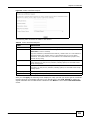
13.1 Overview .......................................................................................................................................167
13.1.1 What You Can Do in this Chapter ........................................................................................167
13.2 What You Need to Know ...............................................................................................................167
13.3 The Local Certificates Screen .......................................................................................................167
13.3.1 Create Certificate Request .................................................................................................168
13.3.2 Load Signed Certificate ......................................................................................................170
13.4 The Trusted CA Screen ................................................................................................................171
13.4.1 View Trusted CA Certificate .................................................................................................172
13.4.2 Import Trusted CA Certificate ..............................................................................................173
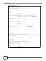
Chapter 14
Wireless .............................................................................................................................................175
14.1 Overview .......................................................................................................................................175
14.1.1 What You Can Do in this Chapter ........................................................................................175
14.1.2 What You Need to Know ......................................................................................................176
14.2 The Basic Screen .........................................................................................................................176
14.3 Wireless Security ..........................................................................................................................177
14.4 MAC Filter .....................................................................................................................................181
14.4.1 The MAC Filter Add Screen
............................................................................................182
14.5 The Advanced Screen ...................................................................................................................182
14.6 Wireless Station Info .....................................................................................................................184
14.7 Technical Reference ......................................................................................................................184
14.7.1 Wireless Network Overview .................................................................................................184
14.7.2 Additional Wireless Terms ...................................................................................................186
14.7.3 Wireless Security Overview .................................................................................................186
14.7.4 Signal Problems ..................................................................................................................189
14.7.5 BSS .....................................................................................................................................189
14.7.6 Preamble Type ....................................................................................................................190
14.7.7 WiFi Protected Setup (WPS) ...............................................................................................190
14.7.8 Vista as a WPS External Registrar ......................................................................................196
Chapter 15
Diagnostic .........................................................................................................................................199
15.1 Overview .......................................................................................................................................199
15.1.1 What You Can Do in this Chapter ........................................................................................199
15.2 What You Need to Know ...............................................................................................................199
15.3 Diagnostics ...................................................................................................................................200
15.4 802.1ag Connectivity Fault Management ......................................................................................200
Chapter 16
Settings..............................................................................................................................................203
Basic Home Station VDSL2 P8701T User’s Guide
7
Table of Contents
16.1 Backup Configuration Using the Web Configurator ......................................................................203
16.2 Restore Configuration Using the Web Configurator ......................................................................203
16.3 Restoring Factory Defaults ............................................................................................................204
Chapter 17
Log ....................................................................................................................................................207
17.1 Overview .......................................................................................................................................207
17.1.1 What You Can Do in this Chapter ........................................................................................207
17.1.2 What You Need To Know .....................................................................................................207
17.2 The System Log Screen ................................................................................................................208
17.3 The System Log Configuration Screen .........................................................................................208
Chapter 18
TR-069 Client..................................................................................................................................... 211
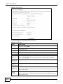
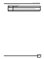
18.1 Overview ....................................................................................................................................... 211
18.2 The TR-069 Client Screen ............................................................................................................ 211
Chapter 19
Internet Time .....................................................................................................................................215
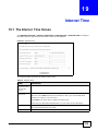
19.1 The Internet Time Screen ...........................................................................................................215
Chapter 20
Access Control .................................................................................................................................217
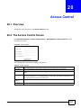
20.1 Overview ......................................................................................................................................217
20.2 The Access Control Screen ..........................................................................................................217
Chapter 21
Software Upgrade .............................................................................................................................219
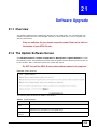
21.1 Overview .......................................................................................................................................219
21.2 The Update Software Screen ........................................................................................................219
Chapter 22
Reboot ...............................................................................................................................................221
22.1 Restart Using the Web Configurator .............................................................................................221
Chapter 23
Troubleshooting................................................................................................................................223
23.1 Power, Hardware Connections, and LEDs ....................................................................................223
23.2 VDSL Router Access and Login ....................................................................................................224
23.3 Internet Access .............................................................................................................................226
23.4 Wireless Internet Access ...............................................................................................................227
23.5 USB Device Connection ................................................................................................................228
23.6 UPnP .............................................................................................................................................228
8
Basic Home Station VDSL2 P8701T User’s Guide
Table of Contents
Appendix A Legal Information..........................................................................................................231
Index ..................................................................................................................................................235
Basic Home Station VDSL2 P8701T User’s Guide
9
Table of Contents
10
Basic Home Station VDSL2 P8701T User’s Guide
P ART I
User’s Guide
11
12
C HAPT ER
1
Introducing the VDSL Router
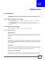
1.1 Overview
The P-8701T is a VDSL2 router and 100/10 Mb Ethernet gateway with a four-port built-in Ethernet
switch and IEEE 802.11n wireless. The VDSL Router allows wired and wireless clients to safely
access the Internet. The built-in firewall blocks unauthorized access to your network.
Only use firmware for your VDSL Router’s specific model. Refer to the
label on the bottom of your VDSL Router.
The VDSL Router has a USB port for sharing files via a USB storage device, sharing a USB printer, or
a 3G dongle for a backup connection.
1.2 How to Manage the VDSL Router
Use the Web Configurator to manage the VDSL Router using a (supported) web browser.
1.3 Good Habits for Managing the VDSL Router
Do the following things regularly to make the VDSL Router more secure and to manage the VDSL
Router more effectively.
• Change the password. Use a password that’s not easy to guess and that consists of different
types of characters, such as numbers and letters.
• Write down the password and put it in a safe place.
1.4 LEDs (Lights)
The following graphic displays the labels of the LEDs.
Basic Home Station VDSL2 P8701T User’s Guide
13
Chapter 1 Introducing the VDSL Router
Figure 1 LEDs on the Device
None of the LEDs are on if the VDSL Router is not receiving power.
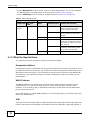
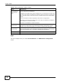
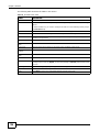
Table 1 LED Descriptions
LED
COLOR
STATUS
DESCRIPTION
POWER
Green
On
The VDSL Router is receiving power and ready for use.
Blinking
The VDSL Router is self-testing.
On
The VDSL Router detected an error while self-testing, or there is a
device malfunction.
Off
The VDSL Router is not receiving power.
Red
Ethernet
1-4
Wifi
Green
Green
Orange
DSL
14
Green
Blinking
Firmware upgrade is in progress.
On
The VDSL Router has a successful 100 Mbps Ethernet connection with a
device on the Local Area Network (LAN).
Blinking
The VDSL Router is sending or receiving data to/from the LAN at 100
Mbps.
Off
The VDSL Router does not have an Ethernet connection with the LAN.
On
The wireless network is activated.
Blinking
The VDSL Router is communicating with other wireless clients.
Blinking
The VDSL Router is setting up a WPS connection.
Off
The wireless network is not activated.
On
The DSL line is up.
Blinking
The VDSL Router is initializing the DSL line.
Off
The DSL line is down.
Basic Home Station VDSL2 P8701T User’s Guide
Chapter 1 Introducing the VDSL Router
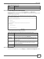
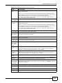
Table 1 LED Descriptions (continued)
LED
COLOR
STATUS
DESCRIPTION
Internet
Green
On
The VDSL Router has an IP connection but no traffic.
Your device has a WAN IP address (either static or assigned by a DHCP
server), PPP negotiation was successfully completed (if used) and the
DSL connection is up.
3G
Blinking
The VDSL Router is sending or receiving IP traffic.
Off
There is no Internet connection or the gateway is in bridged mode.
Red
On
The VDSL Router attempted to make an IP connection but failed.
Possible causes are no response from a DHCP server, no PPPoE
response, PPPoE authentication failed.
Green
On
The 3G backup connection through a 3G USB dongle is connected.
Blinking
The VDSL Router is negotiating a backup connection through a 3G
dongle or sending or receiving traffic through the backup connection.
Fast Blinking
The VDSL Router is sending or receiving traffic through the backup
connection.
On
Authentication of the 3G backup connection through a 3G USB dongle
failed.
Off
The VDSL Router is using the broadband interface.
Red
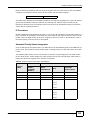
1.5 The RESET Button
If you forget your password or cannot access the web configurator, you will need to use the RESET
button at the back of the device to reload the factory-default configuration file. This deletes all your
and the password will be reset to “1234”.
1
Make sure the POWER LED is green and on (not blinking and not red or flashing red).
2
To set the device back to the factory default settings, press the RESET button for ten seconds or
until the POWER LED begins to blink and then release it. When the POWER LED begins to blink,
the defaults have been restored and the device restarts.
Note: The default username and password are on the label on the bottom of the Device.
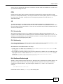
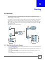
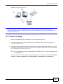
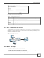
1.6 Wireless Access
The VDSL Router is a wireless Access Point (AP) for wireless clients, such as notebook computers,
smartphones, or tablets. It allows them to connect to the Internet without having to rely on
inconvenient Ethernet cables.
You can connect to your wireless network using the Wifi button, without having to access the Web
Configurator.
Basic Home Station VDSL2 P8701T User’s Guide
15
Chapter 1 Introducing the VDSL Router
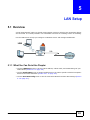
Figure 2 Wireless Access Example
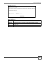
1.6.1 Using the Wifi/WPS Button
Note: The wireless client must be a WPS-aware device (for example, a WPS USB adapter or
PCMCIA card), which can be identified by the WPS logo:
If the wireless network is turned off, press the Wifi/WPS button at the back of the VDSL Router for
one second. Once the Wifi LED turns green, the wireless network is active.
You can also use the Wifi button to quickly set up a secure wireless connection between the VDSL
Router and a WPS-compatible client by adding one device at a time.
To activate WPS:
1
Make sure the POWER LED is green and not blinking.
2
Press the Wifi/WPS button for ten seconds and release it.
Wifi/WPS
16
Basic Home Station VDSL2 P8701T User’s Guide
Chapter 1 Introducing the VDSL Router
3
Enable WPS on another WPS-enabled client device within range of the VDSL Router. If you do not
know how to enable WPS on that client device, refer to its manual. The Wifi LED flashes green and
orange while the VDSL Router sets up a WPS connection with the other WPS enabled client device.
4
Once the connection is successfully made, the Wifi LED shines green.
To turn off the wireless network, press the Wifi/WPS button on the front of the VDSL Router for
one to five seconds. The Wifi LED turns off when the wireless network is off.
1.7 Wall-mounting Instructions
Complete the following steps to hang your VDSL Router on a wall.
Figure 3 Wall-mounting Example
1
Select a position free of obstructions on a sturdy wall.
2
Drill two holes for the screws.
Be careful to avoid damaging pipes or cables located inside the wall
when drilling holes for the screws.
3
Do not insert the screws all the way into the wall. Leave a small gap of about 0.5 cm between the
heads of the screws and the wall.
4
Make sure the screws are snugly fastened to the wall. They need to hold the weight of the VDSL
Router with the connection cables.
5
Align the holes on the back of the VDSL Router with the screws on the wall. Hang the VDSL Router
on the screws.
Basic Home Station VDSL2 P8701T User’s Guide
17
Chapter 1 Introducing the VDSL Router
18
Basic Home Station VDSL2 P8701T User’s Guide
C HAPT ER
2
User Setup Guide
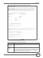
2.1 Access the VDSL Router Configuration
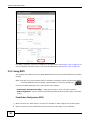
1
Connect to the Web Configurator to configure the VDSL Router. Enter the LAN IP address of the
VDSL Router in your web browser (http://192.168.1.1 by default).
The default password is 1234.
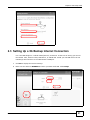
2
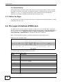
The Network Map screen shows information about the VDSL Router’s network connections and
provides links for configuring settings. Click a link for details.
• Español / English - change the language.
• Change password - change the configuration password (see Section 2.2 on page 20).
• ? - display tips and frequently asked questions.
• Internet - open an Internet connection troubleshooting wizard.
• 3G - configure your 3G connection (see Section 2.3 on page 21).
• ADSL - enter the VDSL Router’s password (see Section 2.4 on page 22).
• Wireless network - set up your wireless network (see Section 2.5 on page 22).
• ? 192.168.1.3x - specify a LAN device’s name and type and open ports to it (see Section 2.7 on
page 30).
Basic Home Station VDSL2 P8701T User’s Guide
19
Chapter 2 User Setup Guide
• Configure applications and ports - open ports for a LAN device (see Section 2.7 on page 30).
2.2 Changing the Configuration Password
Click the Network Map screen’s Change password link (1 in the figure). Enter the VDSL Router’s
password and click Accept.
1
2
Enter your current and new passwords and click Accept.
20
Basic Home Station VDSL2 P8701T User’s Guide
Chapter 2 User Setup Guide
2.3 Setting Up a 3G Backup Internet Connection
Use a 3G USB dongle for a cellular WAN (Internet) connection. At the time of writing you can use
the Huawei 1752, Huawei 1752C, ZTE MF110, or ZTE MF190. Install your 3G SIM card in the 3G
USB dongle and connect it to the VDSL Router’s USB port.
1
Click 3G to display the wireless settings.
2
Make sure the status is ENABLED and enter your SIM card’s PIN. Click Accept.
Basic Home Station VDSL2 P8701T User’s Guide
21
Chapter 2 User Setup Guide
2.4 Setting Your DSL Account’s Username and Password
Click the Network Map screen’s ADSL link (1 in the figure). Enter the VDSL Router’s password and
click Accept.
2
1
Enter your DSL account’s username and password and click Accept.
Try to connect to a website to see if you have correctly set up your Internet connection. Contact
your service provider for any information you need to configure the WAN screens.
2.5 Setting Up a Secure Wireless Network
Thomas sets up a wireless network to give his notebook wireless Internet access. The VDSL Router
serves as an access point (AP) to let the notebook connect to the Internet.
22
Basic Home Station VDSL2 P8701T User’s Guide
Chapter 2 User Setup Guide
Thomas configures the wireless network settings on the VDSL Router and uses WPS (Section 2.5.2
on page 24) or manual configuration (Section 2.5.3 on page 27) to connect his notebook.
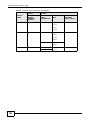
2.5.1 Configuring the Wireless Network Settings
This example uses the following parameters to set up a wireless network.
SSID
Example
Security Level
High (WPA2)
Pre-Shared Key
DoNotStealMyWirelessNetwork
802.11 Mode
802.11b/g/n Mixed
Note: See the sticker on the bottom of the VDSL Router for the default wireless LAN
SSID, security mode, and password.
1
Click Wireless network to display the wireless settings.
2
Click the DISABLED status to set it to ENABLED. Type a name in the Name field. Set the
Security Level to High (WPA2) and enter the Pre-Shared Key in the Key field. Click Accept.
Basic Home Station VDSL2 P8701T User’s Guide
23
Chapter 2 User Setup Guide
Use WPS to wirelessly connect the notebook to the VDSL Router (see Section 2.5.2 on page 24) or
use the notebook’s wireless client to search for the VDSL Router (see Section 2.5.3 on page 27).
2.5.2 Using WPS
This example uses WPS to connect a ZyXEL NWD210N wireless client to the VDSL Router’s wireless
network.
Note: One way to see if the wireless client (a notebook, smartphone, tablet, wireless USB adapter,
or wireless PCMCIA card for example) supports WPS is to look for the WPS logo:
It covers two WPS methods to set up the wireless client settings:
• Push Button Configuration (PBC) - simply press a button. This is the easier method.
• PIN Configuration - enter a wireless client’s Personal Identification Number (PIN) in the VDSL
Router.
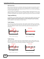
Push Button Configuration (PBC)
24
1
Make sure that your VDSL Router is on and your notebook is within range of the wireless signal.
2
Make sure that you have installed the wireless client driver and utility in your notebook.
Basic Home Station VDSL2 P8701T User’s Guide
Chapter 2 User Setup Guide
3
In the wireless client utility, go to the WPS setting page. Enable WPS and press the Wifi button
(Start or Wifi button).
4
Push and hold the Wifi/WPS button located on the VDSL Router’s rear panel for 10 seconds.
Note: It doesn’t matter which device’s button you press first. You must press the second
button within two minutes of pressing the first one.
Note: The WPS button in the Web Configurator screens also has the same function as the
one on the VDSL Router rear panel: use either.
The VDSL Router sends the wireless network settings to the wireless client. This may take up to two
minutes. Afterwards the wireless client can communicate with the VDSL Router securely.
The following figure shows an example of how to set up a wireless network and its security by
pressing a button on both VDSL Router and wireless client.
Example WPS Process: PBC Method
Wireless Client
VDSL Router
Wifi/WPS
WITHIN 2 MINUTES
Press and hold for
10 seconds
SECURITY INFO
COMMUNICATION
PIN Configuration
When you use the PIN configuration method, you need to use both the VDSL Router’s web
configurator and the wireless client’s utility.
1
Launch your wireless client’s configuration utility. Go to the WPS settings and select the PIN method
to get a PIN number.
Basic Home Station VDSL2 P8701T User’s Guide
25
Chapter 2 User Setup Guide
2
Log into the VDSL Router’s web configurator and click Wireless network > Classic configuration
Wireless > Security. Enable the WPS function and select Enter STA PIN. Enter the PIN number
of the wireless client and click the Add Enrollee button. Click Apply/Save.
3
Activate WPS on the wireless client utility screen within two minutes.
The VDSL Router authenticates the wireless client and sends it the proper configuration settings.
This may take up to two minutes. The wireless client can then communicate with the VDSL Router
securely.
The following figure shows how to set up a wireless network and its security on a VDSL Router and
a wireless client by using PIN method.
26
Basic Home Station VDSL2 P8701T User’s Guide
Chapter 2 User Setup Guide
Example WPS Process: PIN Method
Wireless Client
VDSL Router
WITHIN 2 MINUTES
Authentication by PIN
SECURITY INFO
COMMUNICATION
2.5.3 Without WPS
This example uses Windows XP to connect wirelessly to your VDSL Router.
1
Right-click the wireless adapter icon at the bottom right of your computer monitor. Click View
Available Wireless Networks.
Basic Home Station VDSL2 P8701T User’s Guide
27
Chapter 2 User Setup Guide
2
Select the VDSL Router’s SSID name (“SecureWirelessNetwork” in this example) and click
Connect (A).
A
28
3
Enter the password when prompted and click Connect.
4
You may have to wait several minutes while your computer connects to the wireless network.
5
Congratulations! Browse to your favorite websites. If you cannot, check that you connected to the
correct AP, and the signal strength is OK. Click your wireless adapter’s icon and click Enable. Some
notebooks also have a physical button that enables or disables the wireless adaptor.
Basic Home Station VDSL2 P8701T User’s Guide
Chapter 2 User Setup Guide
2.6 Using Wireless MAC Authentication to Block a
Computer’s Access to the Wireless Network
Use MAC Authentication to block a computer from accessing the wireless network based on the
computer’s MAC address.
Note: MAC Authentication offers limited security.
1
Click Wireless network > Classic configuration > Wireless > MAC Filter. In the MAC Filter
screen, click Add.
2
In the MAC Address field, enter the MAC address of the computer to block and click Apply/Save.
3
The MAC address appears in the MAC List. Set the MAC Restrict Mode to Deny and click Add.
Basic Home Station VDSL2 P8701T User’s Guide
29
Chapter 2 User Setup Guide
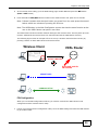
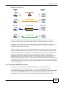
2.7 Setting Up a NAT Virtual Server for a Game Server
This examples configures a virtual server to forward traffic from Civilization IV players on the
Internet (A in the figure below) to a server on a computer behind the VDSL Router.
Note: If firewall is enabled, you may also need to configure a firewall rule for the relevant
ports. See Section 2.9.2 on page 35.
Tutorial: NAT Port Forwarding Setup
D=192.168.1.34
LAN
WAN
TCP/UDP port 6500
UDP ports 2302 and 13139
A
Thomas configures virtual servers to forward TCP and UDP port 6500, and UDP ports 2302 and
13139 traffic to port 6500 at the server’s IP address of 192.168.1.34.
30
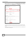
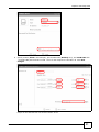
1
Click the Network map screen’s ? 192.168.1.34 link.
2
Specify a name (CivIV in this example) and type (Desktop here). Click Configure applications
and ports.
Basic Home Station VDSL2 P8701T User’s Guide
Chapter 2 User Setup Guide
3
Specify a name (CivIV in this example), port number 6500 (Desktop here), and TCP & UDP. Click
+ and add UDP ports 2302 and 13139. Set it for the computer at 192.168.1.34. Click Save
changes.
Players on the Internet then can access Thomas’ server.
Basic Home Station VDSL2 P8701T User’s Guide
31
Chapter 2 User Setup Guide
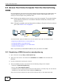
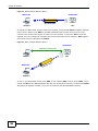
2.8 Access Your Home Computer from the Internet Using
DDNS
It is inconvenient for you to access your home computer from the Internet if your VDSL Router uses
a dynamic WAN IP address since it changes dynamically. Dynamic DNS (DDNS) allows you to
access your home computer using a domain name.
Note: Enable remote desktop server service on your home computer. The remote desktop
server feature covered here is included in Windows Professional, Business, and
Ultimate versions.
Note: If firewall is enabled, you may also need to configure a firewall rule for the relevant
ports. See Section 2.9.2 on page 35.
http://zyxelrouter.dyndns.org
A
a.b.c.d
w.x.y.z
To use this feature, apply for DDNS service at www.dyndns.org or TZO. This tutorial covers:
• Registering a DDNS Account on www.dyndns.org
• Configuring DDNS on Your VDSL Router
• Configuring Port Forwarding on your VDSL Router
• Testing the DDNS Setting
Note: If you have a private WAN IP address, then you cannot use DDNS.
2.8.1 Registering a DDNS Account on www.dyndns.org
1
Open a browser and type http://www.dyndns.org.
2
Apply for a user account. This tutorial uses UserName1 and 12345 as the username and
password.
3
Log into www.dyndns.org using your account.
4
Add a new DDNS host name. This tutorial uses the following settings as an example.
• Hostname: zyxelrouter.dyndns.org
• Service Type: Host with IP address
• IP Address: Enter the WAN IP address that your VDSL Router is currently using. You can find the
IP address on the VDSL Router’s Web Configurator Status page.
Then you will need to configure the same account and host name on the VDSL Router later.
32
Basic Home Station VDSL2 P8701T User’s Guide
Chapter 2 User Setup Guide
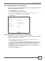
2.8.2 Configuring DDNS on Your VDSL Router
Configure the following settings in the Wireless network > Classic configuration > Advanced
Setup > DNS > Dynamic DNS > Add screen.
• Select DynDNS.org as the D-DNS provider.
• Type zyxelrouter.dyndns.org in the Host Name field.
• Leave the interface set to the default unless you have configured another interface to use.
• Enter the user name (UserName1) and password (12345).
• Click Apply/Save.
2.8.3 Configuring Port Forwarding on your VDSL Router
Configure the following settings in the Wireless network > Classic configuration > Advanced
Setup > NAT > Virtual Servers > Add screen.
• Leave the interface set to the default unless you have configured another interface to use.
• Select Custom Service and type RD in the field.
• Type the LAN IP address of your computer in the Server IP Address field. To check this on your
home computer, click Start, All Programs, Accessories and then Command Prompt. In the
Command Prompt window, type "ipconfig" and then press [ENTER]. This example uses
192.168.1.64. See Configuring Static DHCP to configure a Static DHCP rule for this IP address.
• Type 3389 in the External/Internal Start/End Port fields. This is the listening port for
Windows remote desktop.
• Select the TCP in the Protocol field.
Basic Home Station VDSL2 P8701T User’s Guide
33
Chapter 2 User Setup Guide
Click Apply/Save.
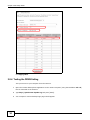
2.8.4 Testing the DDNS Setting
Test your access to your computer from the Internet.
34
1
Open the remote desktop client application on the remote computer (using the IP address a.b.c.d)
that is connected to the Internet.
2
Type http://zyxelrouter.dyndns.org and press [Enter].
3
Your computer’s remote desktop login page should appear.
Basic Home Station VDSL2 P8701T User’s Guide
Chapter 2 User Setup Guide
2.9 Configuring the Firewall
Click Wireless network > Classic configuration > Advanced Setup > Firewall > General
and select Active Firewall to turn on Denial of Service (DoS) protection. Select the default policy’s
Active check box to block sessions initiated from the Internet from coming in through the ppp0.1
WAN interface. Click Apply.
Firewall Example: Edit Rule: Destination Address
2.9.1 Interface Default Policy
Click the Firewall > General screen’s Add button to add an interface default policy to block or
allow sessions initiated from the network connected to an interface. This example allows sessions
initiated from the Internet to come in through the ppp1.1 WAN interface.
Firewall Example: Edit Rule: Destination Address
2.9.2 Firewall Rules
Use Firewall > Rules to control traffic by source and destination IP address and port.
Note: You may need to configure a firewall rule for the relevant ports if you use a NAT
virtual server or DMZ host.
1
Click Add to create a new rule.
Basic Home Station VDSL2 P8701T User’s Guide
35
Chapter 2 User Setup Guide
Firewall Example: Edit Rule: Destination Address
2
36
This example allows incoming TCP or UDP port 6500 traffic from interface ppp0.1.
Basic Home Station VDSL2 P8701T User’s Guide
Chapter 2 User Setup Guide
Firewall Example: Edit Rule: Destination Address
Firewall Example: Edit Rule: Select Customized Services
3
Your new rule displays in the list.
Firewall Example: Edit Rule: Destination Address
2.10 LAN DHCP for IP Addressing Assignment
The following example shows how to configure LAN DHCP settings.
Click Wireless network > Classic configuration > Advanced Setup > LAN to display the LAN
settings. Under the Enable DHCP Server option change the DHCP server IP address range. Set
Leased Time to specify how long to lease an IP address to a LAN computer. Click Apply/Save.
Basic Home Station VDSL2 P8701T User’s Guide
37
Chapter 2 User Setup Guide
Firewall Example: Edit Rule: Destination Address
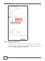
2.10.1 Configuring Static DHCP
Use static DHCP to have the VDSL Router always give the same IP address to a specific computer.
1
38
Click Wireless network > Classic configuration > Advanced Setup > LAN to display the LAN
settings. Under the Static IP Lease List, click Add Entries.
Basic Home Station VDSL2 P8701T User’s Guide
Chapter 2 User Setup Guide
Firewall Example: Edit Rule: Destination Address
2
Enter the computer’s MAC address and the LAN IP address to give the computer and click Apply/
Save.
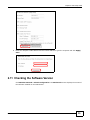
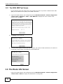
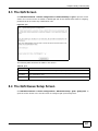
2.11 Checking the Software Version
Click Wireless network > Classic configuration. The Device Info screen displays the version of
the software installed on the VDSL Router.
Basic Home Station VDSL2 P8701T User’s Guide
39
Chapter 2 User Setup Guide
Firewall Example: Edit Rule: Destination Address
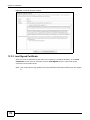
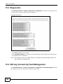
2.12 Restoring to Factory Default
This procedure restores the factory default settings to the VDSL Router.
1
Click Wireless network > Classic configuration > Management > Restore Default >
Restore Default Settings.
Firewall Example: Edit Rule: Destination Address
2
Click OK.
Firewall Example: Edit Rule: Destination Address
3
40
The restore screen displays.
Basic Home Station VDSL2 P8701T User’s Guide
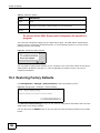
Chapter 2 User Setup Guide
Note: The Power LED flashes and stays on green when ready to reconfigure. Follow the
instructions provided by your ISP to reprogram your modem.
Note: The VDSL Router’s back sticker displays the default LAN IP address, username, and
password.
Firewall Example: Edit Rule: Destination Address
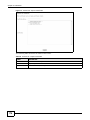
2.13 How to Use File Sharing on the VDSL Router
These sections cover how to use file sharing to allow LAN users to access a USB storage device
connected to the VDSL Router as if it was directly connected to their computers.
Note: Remember to control physical access to the USB drive so someone doesn’t access
files by simply connecting it to a computer.
2.13.1 Set Up File Sharing
1
Connect your USB device to the USB port at the back panel of the VDSL Router.
2
Click Wireless network > Classic configuration > Advanced Setup > USB Services > File
Sharing and enable file sharing. Click Add new user to set up a new file sharing user account.
Basic Home Station VDSL2 P8701T User’s Guide
41
Chapter 2 User Setup Guide
42
3
Enter a user name and password and click Apply.
4
Disable the root account and click Apply/Save.
Basic Home Station VDSL2 P8701T User’s Guide
Chapter 2 User Setup Guide
2.13.2 Access Your Shared Files From a Computer
Note: This example uses Microsoft’s Windows 7 to browse your shared files.
1
Open Windows Explorer and in the address bar type a double backslash “\\” followed by the VDSL
Router’s LAN IP address and press [ENTER].
2
A login screen displays. Type the user name and password you set up for file sharing and click OK.
Note: Once you log into the file share via your VDSL Router, you do not have to log in
again unless you restart your computer or the VDSL Router.
3
Double-click the usbshare folder and browser its contents.
Basic Home Station VDSL2 P8701T User’s Guide
43
Chapter 2 User Setup Guide
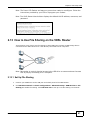
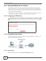
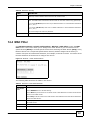
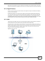
2.14 Using the Media Server Feature
The media server streams video, music, and photo files from a USB storage device to DLNAcompliant media clients on your network. Connect the USB storage device to the VDSL Router’s
USB port. This section gives examples of using the media server with the following media clients:
• Microsoft (MS) Windows Media Player
• ZyXEL DMA-2500, a digital media adapter - see the DMA-2500 Quick Start Guide to set up the
DMA-2500 to work with your television (TV) before using the instructions here.
2.14.1 Configuring the VDSL Router
Click Wireless network > Classic configuration > Advanced Setup > USB Services > Media
Server. The digital media server settings display. Enable the digital media server and click Apply/
Save.
Tutorial: USB Services > Media Server
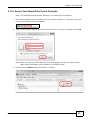
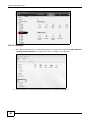
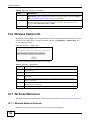
2.14.2 Using Windows Media Player
This section shows you how to play the media files on the USB storage device connected to your
VDSL Router using Windows Media Player.
Tutorial: Media Server Setup (Using Windows Media Player)
USB Storage Device
Computer with
Windows Media Player
VDSL Router
2.14.2.1 Windows Vista
1
44
Open Windows Media Player and click Library > Media Sharing as follows.
Basic Home Station VDSL2 P8701T User’s Guide
Chapter 2 User Setup Guide
Tutorial: Media Sharing using Windows Vista
2
Select Find media that others are sharing in the following screen and click OK.
Tutorial: Media Sharing using Windows Vista (2)
3
The VDSL Router displays as a playlist in the Library screen’s left panel. Click the category icons in
the right panel to display the media files in the USB storage device attached to your VDSL Router.
Basic Home Station VDSL2 P8701T User’s Guide
45
Chapter 2 User Setup Guide
Tutorial: Media Sharing using Windows Vista (3)
P8701T
P8701T
2.14.2.2 Windows 7
1
Open Windows Media Player. It automatically detects the VDSL Router. Right-click Other Libraries
> Refresh Other Libraries if the VDSL Router does not display in the left panel.
Tutorial: Media Sharing using Windows 7 (1)
P8701T
P8701T
2
46
Select a category and wait for Windows Media Player to list the files available.
Basic Home Station VDSL2 P8701T User’s Guide
Chapter 2 User Setup Guide
Tutorial: Media Sharing using Windows 7 (2)
P8701T
P8701T
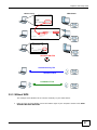
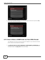
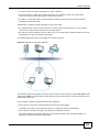
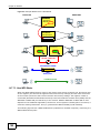
2.14.3 Using a Digital Media Adapter
This section shows you how to use a ZyXEL DMA-2500 to play media files in a USB storage device
connected to the VDSL Router.
Note: Set up your DMA-2500 with the TV according to the instructions in the DMA-2500
Quick Start Guide before using this tutorial.
1
Connect the DMA-2500 to an available LAN port on your VDSL Router.
Tutorial: Media Server Setup (Using DMA)
USB Storage Device
DMA-2500
VDSL Router
2
Turn on the TV and wait for the DMA-2500 Home screen to appear. Using the remote control, go to
MyMedia to open the following screen. Select the VDSL Router as your media server.
Basic Home Station VDSL2 P8701T User’s Guide
47
Chapter 2 User Setup Guide
Tutorial: Media Sharing using DMA-2500
3
The screen lists available media files in the USB storage device. Select a file and push the Play
button in the remote control to open it.
Tutorial: Media Sharing using DMA-2500 (2)
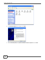
2.15 How to Share a USB Printer via Your VDSL Router
Your VDSL Router can act as a print server and let the computers on your network use the USB
printer connected to the VDSL Router’s USB port.
1
48
Go to Wireless network > Classic configuration > Advanced Setup > USB Services > to
enable the print server function on the VDSL Router. Enter the printer’s name and manufacturer
and model number. Click Apply/Save to save your settings.
Basic Home Station VDSL2 P8701T User’s Guide
Chapter 2 User Setup Guide
2
Connect the USB printer to the VDSL Router if you have not done so already.
3
See Section 2.15.1 on page 49 and/or Section 2.15.2 on page 53 for examples of how to set up a
printer on your computer. The computers on your network must have the printer software already
installed before they can use the printer.
Note: Your printer’s installation instructions may ask that you connect the printer to your
computer. Connect the printer to the VDSL Router instead.
2.15.1 Add a New Printer Using Windows
This example shows how to connect a printer behind the VDSL Router to a computer using the
Windows XP Professional. Some menu items may look different on your operating system.
1
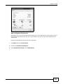
Click Start > Control Panel > Printers and Faxes to open the Printers and Faxes screen. Click
Add a Printer.
Basic Home Station VDSL2 P8701T User’s Guide
49
Chapter 2 User Setup Guide
50
2
The Add Printer Wizard screen displays. Click Next.
3
Select A network printer, or a printer attached to another computer and click Next.
Basic Home Station VDSL2 P8701T User’s Guide
Chapter 2 User Setup Guide
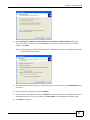
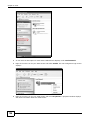
4
Select Connect to a printer on the Internet or on a home or office network: and enter
“http://192.168.1.1:631/printers/USB_PRINTER” as the URL to access the print server (VDSL
Router). Click Next.
Note: If you change the VDSL Router’s LAN IP address, use the new IP address in the URL
to access the print server.
5
Select the make of the printer that you want to connect to the print server in the Manufacturer list
of printers.
6
Select the printer model from the list of Printers.
7
If your printer is not displayed in the list of Printers, insert the printer driver installation CD/disk or
download the driver file to your computer, click Have Disk… and install the new printer driver.
8
Click Next to continue.
Basic Home Station VDSL2 P8701T User’s Guide
51
Chapter 2 User Setup Guide
9
Select Yes to use this printer as the default printer on your computer. Otherwise select No. Click
Next to continue.
10 The following screen shows your current printer settings. Select Finish to complete adding a new
printer.
52
Basic Home Station VDSL2 P8701T User’s Guide
Chapter 2 User Setup Guide
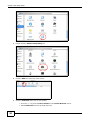
2.15.2 Add a New Printer Using Macintosh OS X
Complete the following steps to set up a print server driver on your Macintosh computer.
2.15.2.1 Mac OS 10.3 and 10.4
This example shows how to connect a printer behind the VDSL Router to your computer using Mac
OS X v10.4.11. Some menu items may look different on your operating system.
1
Click the Finder icon on the Dock (a place holding a series of icons/shortcuts at the bottom of the
desktop) or double-click your Mac hard disk icon (Mac OS X in this example) on your desktop.
2
The Mac HD window displays. Open the Applications folder.
3
Open the Utilities folder.
Basic Home Station VDSL2 P8701T User’s Guide
53
Chapter 2 User Setup Guide
4
Double-click the Printer Setup Utility icon.
5
Click the Add icon at the top of the screen.
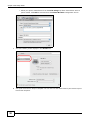
6
Click the IP Printer tab to set up your printer.
• Press the alt key and click More Printers in the Printer Browser screen.
• Select Advanced from the top drop-down list.
54
Basic Home Station VDSL2 P8701T User’s Guide
Chapter 2 User Setup Guide
• Select Internet Printing Protocol using HTTP from the Device drop-down list.
• Enter a descriptive name for the printer in the Device Name field.
• In the Device URL field, enter “http://192.168.1.1:631/printers/USB_PRINTER” as the
URL to access the print server (VDSL Router).
Note: If you change the VDSL Router’s LAN IP address, use the new IP address in the URL
to access the print server.
• Select your printer manufacturer from the Printer Model drop-down list and then select a
printer model. Click Add to save and close the Printer Browser configuration screen.
7
The new network printer displays in the Printer List. The default printer Name displays in bold
type.
8
Your print server driver setup is complete. You can now use the VDSL Router’s print server to print
from a Mac computer.
2.15.2.2 Mac OS 10.5 and 10.6
This example shows how to connect a printer behind the VDSL Router to your computer using Mac
OS X v10.6.2. Some menu items may look different on your operating system.
Basic Home Station VDSL2 P8701T User’s Guide
55
Chapter 2 User Setup Guide
56
1
Click the Finder icon on the Dock or double-click your Mac hard disk icon (Mac OS X in this
example) on your desktop to open the Mac HD window.
2
Open the Applications folder.
3
Double-click the System Preferences icon.
4
Click the Print & Fax icon.
Basic Home Station VDSL2 P8701T User’s Guide
Chapter 2 User Setup Guide
5
Select the Printing tab and click the + icon to add a new printer.
6
Click the Advanced button on the Add Printer toolbar to set up your printer.
If the Advanced button doesn’t appear, Ctrl-click the toolbar, select Customize Toolbar... and
then drag the Advanced button onto the toolbar.
• Select Internet Printing Protocol (HTTP) from the Type drop-down list.
• Select Another Device from the Device drop-down list.
• In the URL field, enter “http://192.168.1.1:631/printers/USB_PRINTER” as the URL to
access the print server (VDSL Router).
Note: If you change the VDSL Router’s LAN IP address, use the new IP address in the URL
to access the print server.
• Enter a descriptive name for the printer and where it is located.
Basic Home Station VDSL2 P8701T User’s Guide
57
Chapter 2 User Setup Guide
• Select your printer manufacturer from the Print Using drop-down list and then select a
printer model. Click Add to save and close the Printer Browser configuration screen.
58
7
The new network printer displays in the Printers list.
8
Your print server driver setup is complete. You can now use the VDSL Router’s print server to print
from a Mac computer.
Basic Home Station VDSL2 P8701T User’s Guide
P ART II
Technical Reference
59
60
C HAPT ER
3
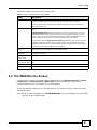
Device Info Screens
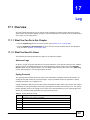
3.1 Overview
After you log into the Web Configurator, the Network Map screen appears. This shows the network
connection status of the Device and clients connected to it.
Use the Device Info screens to look at the current status of the Device, system resources, and
interfaces (LAN, WAN, and WLAN).
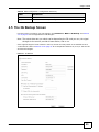
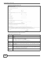
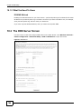
3.2 The Device Info Summary Screen
Log into the VDSL Router’s web configurator and click Wireless network > Classic configuration
to view a summary screen of information about the VDSL Router.
Figure 4 Device Info Summary Screen
Basic Home Station VDSL2 P8701T User’s Guide
61
Chapter 3 Device Info Screens
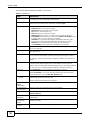
Each field is described in the following table.
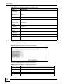
Table 2 Device Info Summary Screen
LABEL
DESCRIPTION
Board ID
This field displays the ID number of the circuit board in the VDSL Router.
Symmetric CPU
Threads
This field displays the number of threads in the VDSL Router’s CPU.
Build
Timestamp
This field displays the date (YYMMDD) and time (HHMM) of the firmware in the VDSL Router.
Software
Version
This field displays the current version of the firmware inside the VDSL Router.
Bootloader
(CFE) Version
This field displays the version of bootloader the VDSL Router is using.
DSL PHY and
Driver Version
This field displays the version of the modem code the VDSL Router is using.
Wireless Driver
Version
This field displays the version of the driver for the VDSL Router’s wireless chipset.
Uptime
This field displays how long the VDSL Router has been running since it last started up.
Line Rate Upstream
This field displays the WAN port’s sending traffic speed.
Line Rate Downstream
This field displays the WAN port’s receiving traffic speed.
LAN IPv4
Address
This field displays the current IP address of the VDSL Router in the LAN.
Default
Gateway
This field displays the IP address of the gateway through which the VDSL Router sends
traffic unless it matches a static route.
Primary DNS
Server
The VDSL Router tries this DNS server first when it needs to resolve a domain name into a
numeric IP address.
Secondary DNS
Server
The VDSL Router uses this DNS server first when it needs to resolve a domain name into a
numeric IP address if the primary DNS server does not respond.
LAN IPv6
Address
(Global)
This field displays the current global IPv6 address of the VDSL Router.
LAN IPv6
Address (Link)
This field displays the current IPv6 address of the VDSL Router in the LAN.
Default IPv6
Gateway
This field displays the IPv6 address of the gateway through which the VDSL Router sends
IPv6 traffic unless it matches a static route.
Date/Time
This field displays the VDSL Router’s current day of the week, month, hour, minute, second,
and year.
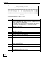
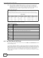
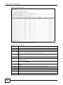
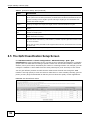
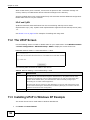
3.3 The WAN Info Screen
Log into the VDSL Router’s web configurator and click Wireless network > Classic configuration
> Device Info > WAN to view a summary screen of information about the VDSL Router’s WAN
connections.
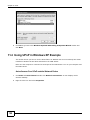
62
Basic Home Station VDSL2 P8701T User’s Guide
Chapter 3 Device Info Screens
Figure 5 WAN Info Screen
Each field is described in the following table.
Table 3 WAN Info Screen
LABEL
DESCRIPTION
Interface
This shows the name of the interface used by this connection.
A default name ipoa*, pppoa*, atm* or ptm* indicates DSL port. The ppp* indicates a
PPP connection via any one of the WAN interface.
The number after the dot (.) represents the VLAN ID number assigned to traffic sent
through this connection. The number after the underscore (_) represents the index number
of connections through the same interface.
(null) means the entry is not valid.
Description
This is the service name of this connection.
0 and 35 or 0 and 1 are the default VPI and VCI numbers. The last number represents the
index number of connections over the same PVC or the VLAN ID number assigned to traffic
sent through this connection.
(null) means the entry is not valid.
Type
This shows the method of encapsulation used by this connection.
VlanMuxID
This indicates the VLAN ID number assigned to traffic sent through this connection. This
displays N/A when there is no VLAN ID number assigned.
IPv6
This displays whether or not IPv6 is enabled on the interface.
Igmp
This shows whether IGMP (Internet Group Multicast Protocol) is activated or not for this
connection. IGMP is not available when the connection uses the bridging service.
MLD
This shows whether Multicast Listener Discovery (MLD) is activated or not for this
connection. MLD is not available when the connection uses the bridging service.
NAT
This shows whether NAT is activated or not for this interface. NAT is not available when the
connection uses the bridging service.
Status
This displays the connection state or Unconfigured if the interface has not yet been
configured.
IPv4 Address
This displays the interface’s current IPv4 address if it has one. Click connect to initiate the
WAN interface’s connection.
IPv6 Address
This displays the interface’s current IPv6 address if it has one. Click connect to initiate the
WAN interface’s connection.
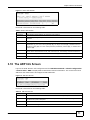
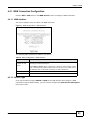
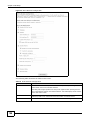
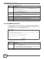
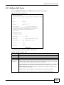
3.4 The 3G Status Screen
Log into the VDSL Router’s web configurator and click Wireless network > Classic configuration
> Device Info > 3G to view a summary screen of information about the VDSL Router’s 3G
connection.
Basic Home Station VDSL2 P8701T User’s Guide
63
Chapter 3 Device Info Screens
Figure 6 3G Status Screen
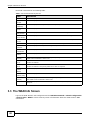
Each field is described in the following table.
Table 4 3G Status Screen
LABEL
DESCRIPTION
Status
•
•
•
•
•
•
•
•
•
NoDevice when no 3G card is inserted,
Disabled when the 3G WAN is not activated,
Up when the 3G connection is up,
Down when the 3G connection is down,
NoResponse when there is no response from the inserted 3G card,
InvalidPIN if the PIN code you entered in the WAN > 3G Backup screen is not the
right one for the 3G card you inserted,
NeedPUK if you enter the PIN (Personal Identification Number) code incorrectly for
three times and the SIM card is blocked by your ISP,
DialFail when the VDSL Router fails to dial up a 3G connection.
or InvalidSIM when the SIM card is damaged or not inserted.
If a link displays in this field, click the link to view more status information or enter the
correct PIN or PUK (Personal Unblocking Key) code.
64
Service
Provider
This displays the name of your 3G network service provider.
Signal Strength
This displays the 3G connection’s signal quality.
Connection
Uptime
This displays how long the 3G connection has been connected since it last came up.
3G Card
Manufacturer
This displays the name of the company that produced the 3G USB dongle.
3G Card Model
This displays the model name of the 3G USB dongle.
3G Card F/W
Version
This displays the software version of the 3G USB dongle.
3G Card IMEI
IMEI (International Mobile Equipment Identity) is a 15-digit code in decimal format that
identifies the 3G device.
SIM Card IMSI
IMSI (International Mobile Subscriber Identity) is a 15-digit code that identifies the SIM
card.
Basic Home Station VDSL2 P8701T User’s Guide
Chapter 3 Device Info Screens
3.5 The LAN Statistics Screen
Log into the VDSL Router’s web configurator and click Wireless network > Classic configuration
> Device Info > Statistics > LAN to view a summary screen of information about the VDSL
Router’s LAN connections.
Figure 7 LAN Statistics Screen
Each field is described in the following table.
Table 5 LAN Statistics Screen
LABEL
DESCRIPTION
Interface
These fields identify the LAN interfaces. eth0 ~ eth3 represent the ethernet LAN ports 1 ~
4. wlo represents the wireless LAN interface.
Received /
Transmitted
These fields display the number of bytes, packets, error packets, and dropped packets for
each interface.
Received
Bytes
This indicates the number of bytes received on this interface.
Pkts
This indicates the number of packets received on this interface.
Errs
This indicates the number of frames with errors received on this interface.
Drops
This indicates the number of received packets dropped on this interface.
Transmitted
Bytes
This indicates the number of bytes transmitted on this interface.
Pkts
This indicates the number of transmitted packets on this interface.
Errs
This indicates the number of frames with errors transmitted on this interface.
Drops
This indicates the number of outgoing packets dropped on this interface.
Reset Statistics
Click this to clear the screen’s statistics counters.
3.6 The WAN Statistics Screen
Log into the VDSL Router’s web configurator and click Wireless network > Classic configuration
> Device Info > Statistics > WAN Service to view a summary screen of information about the
VDSL Router’s WAN connections.
Basic Home Station VDSL2 P8701T User’s Guide
65
Chapter 3 Device Info Screens
Figure 8 WAN Statistics Screen
Each field is described in the following table.
Table 6 WAN Statistics Screen
LABEL
DESCRIPTION
Interface
This shows the name of the WAN interface used by this connection.
The default name ipoa*, pppoa*, atm* or ptm* indicates the DSL port. ppp* indicates a
PPP connection via any one of the WAN interfaces. ppp3G0 indicates a PPP connection
through the 3G interface.
The number after the dot (.) represents the VLAN ID number assigned to traffic sent
through this connection. The number after the underscore (_) represents the index number
of connections through the same interface.
(null) means the entry is not valid.
Description
This shows the descriptive name of this connection.
ATM interfaces include the VPI and VCI. 0 and 35 or 0 and 1 are the default VPI and VCI
numbers. The last number represents the index number of connections over the same PVC
or the VLAN ID number assigned to traffic sent through this connection.
(null) means the entry is not valid.
Received
Bytes
This indicates the number of bytes received on this interface.
Pkts
This indicates the number of packets received on this interface.
Errs
This indicates the number of frames with errors received on this interface.
Drops
This indicates the number of received packets dropped on this interface.
Transmitted
Bytes
This indicates the number of bytes transmitted on this interface.
Pkts
This indicates the number of transmitted packets on this interface.
Errs
This indicates the number of frames with errors transmitted on this interface.
Drops
This indicates the number of outgoing packets dropped on this interface.
Reset Statistics
Click this to clear the screen’s statistics counters.
3.7 The xTM Statistics Screen
Log into the VDSL Router’s web configurator and click Wireless network > Classic configuration
> Device Info > Statistics > xTM to display ATM or PTM connection information.
66
Basic Home Station VDSL2 P8701T User’s Guide
Chapter 3 Device Info Screens
Figure 9 xTM Statistics Screen
Each field is described in the following table.
Table 7 xTM Statistics Screen
LABEL
DESCRIPTION
Port Number
This identifies the ATM or PTM port.
In Octets
This displays the number of 8-bit binary digits (bytes) received through the port.
Out Octets
This displays the number of 8-bit binary digits (bytes) sent through the port.
In Packets
This displays the number of packets received through the port.
Out Packets
This displays the number of packets sent through the port.
In OAM Cells
This displays the number of OAM (Operational, Administration and Maintenance) cells
received through the port.
Out OAM Cells
This displays the number of OAM cells sent through the port.
In ASM Cells
This displays the number of ASM (Autonomous Status Message) cells received through the
port.
Out ASM Cells
This displays the number of ASM cells sent through the port.
In Packet Errors This displays the number of errored packets received on the port.
In Cell Errors
This displays the number of errored cells received on the port.
Reset
Click this to clear the screen’s statistics counters.
3.8 The xDSL Statistics Screen
Log into the VDSL Router’s web configurator and click Wireless network > Classic configuration
> Device Info > Statistics > xDSL to display information about the VDSL Router’s VDSL or ADSL
connections.
Basic Home Station VDSL2 P8701T User’s Guide
67
Chapter 3 Device Info Screens
Figure 10 xDSL Statistics Screen
Each field is described in the following table.
Table 8 xDSL Statistics Screen
68
LABEL
DESCRIPTION
Mode
This field identifies the DSL mode of the DSL connection.
Traffic Type
This displays the type of traffic the DSL port is sending and receiving.
Status
This displays the current state of setting up the DSL connection.
Link Power
State
This displays the DSL connection’s current power usage or power saving mode. null displays
when there is no DSL connection.
Downstream
These are the statistics for the traffic direction coming into the port from the service
provider.
Basic Home Station VDSL2 P8701T User’s Guide
Chapter 3 Device Info Screens
Table 8 xDSL Statistics Screen (continued)
LABEL
DESCRIPTION
Upstream
These are the statistics for the traffic direction going out from the port to the service
provider.
Line Coding
(Trellis)
This displays whether or not the port is using Trellis coding for traffic. Trellis coding helps to
reduce the noise in ADSL transmissions. Trellis may reduce throughput but it makes the
connection more stable.
SNR Margin
(0.1 dB)
This displays the Signal-to-Noise Ratio margin (in 0.1 dB). A DMT sub-carrier’s SNR is the
ratio between the received signal power and the received noise power. The signal-to-noise
ratio margin is the maximum that the received noise power could increase with the system
still being able to meet its transmission targets.
Attenuation
(0.1 dB)
This displays the line attenuation, measured in tenths of a decibel (0.1 dB). This attenuation
is the difference between the power transmitted at the near-end and the power received at
the far-end. Attenuation is affected by the channel characteristics (wire gauge, quality,
condition and length of the physical line).
Output Power
(0.1 dBm)
This displays the far end actual aggregate transmit power (in dBm). Downstream is how
much port the service provider is using to transmit to the port. Upstream is how much
power the port is using to transmit to the service provider.
Attainable Rate
(Kbps):
These are the highest theoretically possible transfer rates at which the port could send and
receive data.
Rate (Kbps)
This displays the data transfer rates at which the port is receiving and sending.
Super Frames
This displays the number of ADSL superframes the DSL connection received and
transmitted. Each superframe contains 68 ADSL data frames and a one-frame synch symbol
for a total number of 69 frames.
Super Frame
Errors
This displays the number of errored ADSL superframes the DSL connection received and
transmitted.
RS Words
This displays the number of Reed Solomon error correction words for received and
transmitted traffic.
RS Correctable
Errors
This displays the number of errored packets corrected by Reed Solomon error correction for
received and transmitted traffic.
RS
Uncorrectable
Errors
This displays the number of errored packets that Reed Solomon error correction could not
correct for received and transmitted traffic.
HEC Errors
Header Error Control (HEC) checks for errors in packet headers.
OCD Errors
The number of Out of Cell Delineation errors for received and transmitted traffic. An OCD
error means seven consecutive ATM cells had Header Error Control (HEC) violations.
LCD Errors
The number of Loss of Cell Delineation errors for received and transmitted traffic. An LCD
state means an OCD condition persisted for 4 milliseconds.
Total Cells
This displays the total number of DSL cells including headers.
Data Cells
This displays the number of data payload DSL cells, excluding headers.
Bit Errors
This displays the number of errored bits.
Total ES
This displays the number of Errored Seconds meaning the number of seconds containing at
least one errored block or at least one defect.
Total SES
This displays the number of Severely Errored Seconds meaning the number of seconds
containing 30% or more errored blocks or at least one defect. This is a subset of ES.
Total UAS
This displays the number of UnAvailable Seconds.
xDSL BER Test
Click this to open a screen where you can perform a ADSL Bit Error Rate (BER) test to
determine the quality of the ADSL connection.
Reset Statistics
Click this to clear the screen’s statistics counters.
Basic Home Station VDSL2 P8701T User’s Guide
69
Chapter 3 Device Info Screens
3.8.1 The ADSL BER Test Screen
Do the following while the VDSL Router has an ADSL connection to perform a ADSL Bit Error Rate
(BER) test to determine the quality of the ADSL connection.
1
Log into the VDSL Router’s web configurator and click Wireless network > Classic configuration
> Device Info > Statistics > xDSL > xDSL BER Test to display this screen. Select a test
duration and click Start.
2
Click Stop to finish the test.
3
The test results display including the test’s duration, the number of bits transferred, the number of
errored bits, and the ratio of errored bits to transmitted bits.
3.9 The Route Info Screen
Log into the VDSL Router’s web configurator and click Wireless network > Classic configuration
> Device Info > Route to display the VDSL Router’s routing table.
70
Basic Home Station VDSL2 P8701T User’s Guide
Chapter 3 Device Info Screens
Figure 11 Route Info Screen
Each field is described in the following table.
Table 9 Route Info Screen
LABEL
DESCRIPTION
Destination
This displays the IP address to which this entry applies.
Gateway
This displays the gateway the VDSL Router uses to send traffic to the entry’s destination
address.
Subnet Mask
This displays the subnet mask of the destination net.
Flag
This displays whether the route is up (U), the VDSL Router drops packets for this
destination (!), the route uses a gateway (G), the target is a host (H), reinstate route for
dynamic routing (R), the route was dynamically installed by redirect (D), or modified from
redirect (M).
Metric
The metric represents the “cost” of transmission for routing purposes. IP routing uses hop
count as the measurement of cost, with a minimum of 1 for directly-connected networks.
Service
The name of a specific service to which the route applies if one is specified.
Interface
The interface through which this route sends traffic.
3.10 The ARP Info Screen
Log into the VDSL Router’s web configurator and click Wireless network > Classic configuration
> Device Info > ARP to display Address Resolution Protocol information. This screen lists the IP
addresses the VDSL Router has mapped to MAC addresses.
Figure 12 ARP Info Screen
Each field is described in the following table.
Table 10 ARP Info Screen
LABEL
DESCRIPTION
IP address
The learned IP address of a device connected to one of the system’s ports.
Flags
Static - static entry, Dynamic - dynamic entry that is not yet complete, Complete dynamic entry that is complete.
HW Address
The MAC address of the device with the listed IP address.
Device
The interface through which the VDSL Router sends traffic to the device listed in the entry.
Basic Home Station VDSL2 P8701T User’s Guide
71
Chapter 3 Device Info Screens
3.11 The DHCP Leases Screen
Log into the VDSL Router’s web configurator and click Wireless network > Classic configuration
> Device Info > DHCP to display the VDSL Router’s list of IP address currently leased to DHCP
clients.
Figure 13 DHCP Leases Screen
Each field is described in the following table.
Table 11 DHCP Leases Screen
72
LABEL
DESCRIPTION
Hostname
This field displays the name used to identify this device on the network (the computer
name). The VDSL Router learns these from the DHCP client requests. “None” shows here for
a static DHCP entry.
MAC Address
This field displays the MAC address to which the IP address is currently assigned or for
which the IP address is reserved. Click the column’s heading cell to sort the table entries by
MAC address. Click the heading cell again to reverse the sort order.
IP Address
This field displays the IP address currently assigned to a DHCP client or reserved for a
specific MAC address. Click the column’s heading cell to sort the table entries by IP address.
Click the heading cell again to reverse the sort order.
Expires In
This field displays how much longer the IP address is leased to the DHCP client.
Basic Home Station VDSL2 P8701T User’s Guide
C HAPT ER
4
WAN
4.1 Overview
This chapter discusses the VDSL Router’s WAN screens. Use these screens to configure your VDSL
Router for Internet access.
A WAN (Wide Area Network) connection is an outside connection to another network or the
Internet. It connects your private networks, such as a LAN (Local Area Network) and other
networks, so that a computer in one location can communicate with computers in other locations.
Figure 14 LAN and WAN
WAN
3G (third generation) standards for the sending and receiving of voice, video, and data in a mobile
environment.
You can attach a 3G wireless adapter to the USB port and set the VDSL Router to use this 3G
connection as your WAN or a backup when the wired WAN connection fails.
Figure 15 3G WAN Connection
4.1.1 What You Can Do in this Chapter
• Use the Layer 2 Interface screens to view, remove or add layer-2 WAN interfaces (Section 4.2
on page 76 and Section 4.3 on page 79).
Basic Home Station VDSL2 P8701T User’s Guide
73
Chapter 4 WAN
• Use the WAN Service screens to view, remove or add a WAN interface. You can also configure
the WAN settings on the VDSL Router for Internet access (Section 4.4 on page 81).
• Use the 3G Backup screen to configure 3G WAN connection (Section 4.5 on page 95).
Table 12 WAN Setup Overview
LAYER-2 INTERFACE
CONNECTION
ADSL/VDSL
over PTM
ADSL over ATM
INTERNET CONNECTION
DSL LINK
TYPE
MODE
ENCAPSULATION
CONNECTION SETTINGS
N/A
Routing
PPPoE
PPP information, IPv4/IPv6 IP
address, routing feature, DNS
server, VLAN, QoS, and MTU
IPoE
IPv4/IPv6 IP address, routing
feature, DNS server, VLAN, QoS,
and MTU
Bridge
N/A
VLAN and QoS
Routing
PPPoE/PPP0A
ATM PCV configuration, PPP
information, IPv4/IPv6 IP address,
routing feature, DNS server, VLAN,
QoS, and MTU
IPoE/IPoA
ATM PCV configuration, IPv4/IPv6
IP address, routing feature, DNS
server, VLAN, QoS, and MTU
N/A
ATM PCV configuration, and QoS
EoA
Bridge
4.1.2 What You Need to Know
The following terms and concepts may help as you read this chapter.
Encapsulation Method
Encapsulation is used to include data from an upper layer protocol into a lower layer protocol. To set
up a WAN connection to the Internet, you need to use the same encapsulation method used by your
ISP (Internet Service Provider). If your ISP offers a dial-up Internet connection using PPPoE (PPP
over Ethernet), they should also provide a username and password (and service name) for user
authentication.
WAN IP Address
The WAN IP address is an IP address for the VDSL Router, which makes it accessible from an
outside network. It is used by the VDSL Router to communicate with other devices in other
networks. It can be static (fixed) or dynamically assigned by the ISP each time the VDSL Router
tries to access the Internet.
If your ISP assigns you a static WAN IP address, they should also assign you the subnet mask and
DNS server IP address(es).
ATM
Asynchronous Transfer Mode (ATM) is a WAN networking technology that provides high-speed data
transfer. ATM uses fixed-size packets of information called cells. With ATM, a high QoS (Quality of
74
Basic Home Station VDSL2 P8701T User’s Guide
Chapter 4 WAN
Service) can be guaranteed. ATM uses a connection-oriented model and establishes a virtual circuit
(VC) between Finding Out More
PTM
Packet Transfer Mode (PTM) is packet-oriented and supported by the VDSL2 standard. In PTM,
packets are encapsulated directly in the High-level Data Link Control (HDLC) frames. It is designed
to provide a low-overhead, transparent way of transporting packets over DSL links, as an
alternative to ATM.
3G
3G (Third Generation) is a digital, packet-switched wireless technology. Bandwidth usage is
optimized as multiple users share the same channel and bandwidth is only allocated to users when
they send data. It allows fast transfer of voice and non-voice data and provides broadband Internet
access to mobile devices.
IPv6 Introduction
IPv6 (Internet Protocol version 6), is designed to enhance IP address size and features. The
increase in IPv6 address size to 128 bits (from the 32-bit IPv4 address) allows up to 3.4 x 1038 IP
addresses. The VDSL Router can use IPv4/IPv6 dual stack to connect to IPv4 and IPv6 networks,
and supports IPv6 rapid deployment (6RD).
IPv6 Addressing
The 128-bit IPv6 address is written as eight 16-bit hexadecimal blocks separated by colons (:). This
is an example IPv6 address 2001:0db8:1a2b:0015:0000:0000:1a2f:0000.
IPv6 addresses can be abbreviated in two ways:
• Leading zeros in a block can be omitted. So 2001:0db8:1a2b:0015:0000:0000:1a2f:0000 can
be written as 2001:db8:1a2b:15:0:0:1a2f:0.
• Any number of consecutive blocks of zeros can be replaced by a double colon. A double colon can
only appear once in an IPv6 address. So 2001:0db8:0000:0000:1a2f:0000:0000:0015 can be
written as 2001:0db8::1a2f:0000:0000:0015, 2001:0db8:0000:0000:1a2f::0015,
2001:db8::1a2f:0:0:15 or 2001:db8:0:0:1a2f::15.
IPv6 Prefix and Prefix Length
Similar to an IPv4 subnet mask, IPv6 uses an address prefix to represent the network address. An
IPv6 prefix length specifies how many most significant bits (start from the left) in the address
compose the network address. The prefix length is written as “/x” where x is a number. For
example,
2001:db8:1a2b:15::1a2f:0/32
means that the first 32 bits (2001:db8) is the subnet prefix.
Basic Home Station VDSL2 P8701T User’s Guide
75
Chapter 4 WAN
IPv6 Subnet Masking
Both an IPv6 address and IPv6 subnet mask compose of 128-bit binary digits, which are divided
into eight 16-bit blocks and written in hexadecimal notation. Hexadecimal uses four bits for each
character (1 ~ 10, A ~ F). Each block’s 16 bits are then represented by four hexadecimal
characters. For example, FFFF:FFFF:FFFF:FFFF:FC00:0000:0000:0000.
4.1.3 Before You Begin
You need to know your Internet access settings such as encapsulation and WAN IP address. Get this
information from your ISP.
4.2 The Layer-2 Interface ATM Screen
The VDSL Router must have a layer-2 interface to allow users to use the DSL port to access the
Internet. The screen varies depending on the interface type you select. Log into the VDSL Router’s
web configurator and click Wireless network > Classic configuration > Advanced Setup >
Layer2 Interface > ATM Interface to manage the ATM layer-2 interfaces.
Note: The ATM and PTM layer-2 interfaces cannot work at the same time.
Figure 16 Layer-2 Interface: ATM
The following table describes the fields in this screen.
Table 13 Layer-2 Interface: ATM
76
LABEL
DESCRIPTION
Interface
The name of a configured layer-2 interface.
Vpi
This displays the Virtual Path Identifier (VPI).
Vci
This displays the Virtual Channel Identifier (VCI).
DSL Latency
This displays whether the ATM interface uses interleave delay (Path1) or fast mode with
no interleave delay (Path0).
Category
This displays the ATM traffic class.
Peak Cell Rate
This displays the maximum rate at which the sender can send cells.
Sustainable Cell
Rate
This displays the average cell rate (long-term) at which the sender can send cells.
Max Burst Size
This displays the maximum number of cells that can be sent at the peak rate.
Link Type
This is the DSL link type of the ATM layer-2 interface.
Conn Mode
This shows the connection mode of the layer-2 interface.
Basic Home Station VDSL2 P8701T User’s Guide
Chapter 4 WAN
Table 13 Layer-2 Interface: ATM (continued)
LABEL
DESCRIPTION
IP QoS
This displays whether QoS (Quality of Service) is enabled on the interface.
MPAAL
Prec/Alg/Wght
This displays the interface’s default queue precedence, queuing algorithm, and weighted
round robin weight.
Remove
Select an interface and click the Remove button to delete it. You cannot remove a layer2 interface when a WAN service is associated with it.
Add
Click this button to create a new ATM layer-2 interface.
4.2.1 Layer-2 ATM Interface Configuration
Click the Add button in the Layer2 Interface: ATM screen to open the following screen. Use this
screen to create a new layer-2 interface. You can have multiple ATM layer-2 interfaces using
different VPI and/or VCI values. The screen varies depending on the interface type you select.
Figure 17 DSL ATM Interface Configuration
Basic Home Station VDSL2 P8701T User’s Guide
77
Chapter 4 WAN
The following table describes the fields in this screen.
Table 14 Layer-2 ATM Interface Configuration
LABEL
DESCRIPTION
ATM PVC
Configuration
VPI (Virtual Path Identifier) and VCI (Virtual Channel Identifier) define a virtual circuit.
This section is available only when you configure an ATM layer-2 interface.
VPI
The valid range for the VPI is 0 to 255. Enter the VPI assigned to you.
VCI
The valid range for the VCI is 32 to 65535 (0 to 31 is reserved for local management of
ATM traffic). Enter the VCI assigned to you.
Select DSL Latency
Select Path0 (Fast) to use no interleaving and have faster transmission (a “fast
channel”). Suitable only for a good line with little need for error correction.
At the time of writing the VDSL Router supports fast mode only and interleaved is
reserved for future use.
Select DSL Link
Type
Select EoA (Ethernet over ATM) to have an Ethernet header in the packet, so that you
can have multiple services/connections over one PVC. You can set each connection to
have its own MAC address or all connections share one MAC address but use different
VLAN IDs for different services. EoA supports ENET ENCAP (IPoE), PPPoE and RFC1483/
2684 bridging encapsulation methods.
Select PPPoA (PPP over ATM) to allow just one PPPoA connection over a PVC.
Select IPoA (IP over ATM) to allow just one RFC 1483 routing connection over a PVC.
Encapsulation
Mode
Select the ISP’s method of multiplexing.
•
•
•
•
Service Category
VC/MUX: In VC multiplexing, each protocol is carried on a separate ATM virtual
circuit (VC). To transport multiple protocols, the VDSL Router needs separate VCs.
There is a binding between a VC and the type of the network protocol carried on the
VC. This reduces payload overhead since there is no need to carry protocol
information in each Protocol Data Unit (PDU) payload.
LLC/SNAP-BRIDGING: In LCC encapsulation, bridged PDUs are encapsulated by
identifying the type of the bridged media in the SNAP header. This is available only
when you select EoA in the Select DSL Link Type field.
LLC/ENCAPSULATION: More than one protocol can be carried over the same VC.
This is available only when you select PPPoA in the Select DSL Link Type field.
LLC/SNAP-ROUTING: In LCC encapsulation, bridged PDUs are encapsulated by
identifying the type of the bridged media in the SNAP header. This is available only
when you select EoA in the Select DSL Link Type field.
Select UBR Without PCR or UBR With PCR for applications that are non-time
sensitive, such as e-mail.
Select CBR (Continuous Bit Rate) to specify fixed (always-on) bandwidth for voice or
data traffic.
Select Non Realtime VBR (non real-time Variable Bit Rate) for connections that do not
require closely controlled delay and delay variation.
Select Realtime VBR (real-time Variable Bit Rate) for applications with bursty
connections that require closely controlled delay and delay variation.
Peak Cell Rate
Divide the DSL line rate (bps) by 424 (the size of an ATM cell) to find the Peak Cell Rate
(PCR). This is the maximum rate at which the sender can send cells. Type the PCR here.
Sustainable Cell
Rate
The Sustain Cell Rate (SCR) sets the average cell rate (long-term) that can be
transmitted. Type the SCR, which must be less than the PCR. Note that system default is
0 cells/sec.
This field is not available when you select UBR Without PCR.
This field is available only when you select Non Realtime VBR or Realtime VBR.
Maximum Burst
Size
Maximum Burst Size (MBS) refers to the maximum number of cells that can be sent at
the peak rate. Type the MBS, which is less than 65535.
This field is available only when you select Non Realtime VBR or Realtime VBR.
78
Basic Home Station VDSL2 P8701T User’s Guide
Chapter 4 WAN
Table 14 Layer-2 ATM Interface Configuration (continued)
LABEL
DESCRIPTION
Scheduler
Select the scheduler to use for queues that have the same precedence as the default
queue. Queuing applies only when a port has more traffic than it can handle.
Weighted Round Robin scheduling services queues of the same priority level on a
rotating basis based on their queue weight. The higher a queue’s weight, the more
service it gets. This queuing mechanism divides any available bandwidth across the
different traffic queues and returns to queues that have not yet emptied.
Weighted Fair Queuing guarantees each queue's minimum bandwidth based on its
queue weight during traffic congestion. This queuing mechanism divides any available
bandwidth across the different traffic queues. Weighted fair queuing handles packets of
various sizes better than weighted round robin queuing does.
Default Queue
Weight
Specify the VC’s weight for weighed fair queuing. The higher the weight, the bigger
portion of the bandwidth the VC gets.
Default Queue
Precedence
Specify the VC’s priority for weighed fair queuing. The smaller the number the higher
the priority.
VC WRR Weight
Specify the VC’s weight for weighted round robin queuing. The higher the weight, the
bigger portion of the bandwidth the VC gets.
VC Precedence
Specify the VC’s priority for weighted round robin queuing. The smaller the number the
higher the priority.
Back
Click this button to return to the previous screen without saving any changes.
Apply/Save
Click this button to save your changes and go back to the previous screen.
4.3 The Layer-2 Interface PTM Screen
The VDSL Router must have a layer-2 interface to allow users to use the DSL port to access the
Internet. The screen varies depending on the interface type you select. Log into the VDSL Router’s
web configurator and click Wireless network > Classic configuration > Advanced Setup >
Layer2 Interface > PTM Interface to manage the PTM layer-2 interfaces.
Note: The ATM and PTM layer-2 interfaces cannot work at the same time.
Figure 18 Layer-2 Interface: PTM
Basic Home Station VDSL2 P8701T User’s Guide
79
Chapter 4 WAN
The following table describes the fields in this screen.
Table 15 Layer-2 Interface: PTM
LABEL
DESCRIPTION
Interface
The name of a configured layer-2 interface.
DSL Latency
This displays whether the ATM interface uses interleave delay (Path1) or fast mode with
no interleave delay (Path0).
PTM Priority
This does not apply at the time of writing.
Conn Mode
This shows the connection mode of the layer-2 interface.
IP QoS
This displays whether QoS (Quality of Service) is enabled on the interface.
Remove
Select an interface and click the Remove button to delete it. You cannot remove a layer2 interface when a WAN service is associated with it.
Add
Click this button to create a new ATM layer-2 interface.
4.3.1 Layer-2 PTM Interface Configuration
Click the Add button in the Layer2 Interface: PTM screen to open the following screen. Use this
screen to create a new layer-2 interface.
Figure 19 DSL PTM Interface Configuration
80
Basic Home Station VDSL2 P8701T User’s Guide
Chapter 4 WAN
The following table describes the fields in this screen.
Table 16 Layer-2 PTM Interface Configuration
LABEL
DESCRIPTION
Select DSL Latency
Select Path0 (Fast) to use no interleaving and have faster transmission (a “fast
channel”). Suitable only for a good line with little need for error correction.
At the time of writing the VDSL Router supports fast mode only and interleaved is
reserved for future use.
Scheduler
Select the scheduler to use for queues that have the same precedence as the default
queue.
Weighted Round Robin scheduling services queues of the same priority level on a
rotating basis based on their queue weight. The higher a queue’s weight, the more
service it gets. This queuing mechanism divides any available bandwidth across the
different traffic queues and returns to queues that have not yet emptied.
During traffic congestion Weighted Fair Queuing guarantees each queue's minimum
bandwidth based on its default queue weight. This queuing mechanism divides any
available bandwidth across the different traffic queues. Weighted fair queuing applies
only when a port has more traffic than it can handle.
Default Queue
Weight
Specify the PTM interface’s weight for weighed fair queuing. The higher the weight, the
bigger portion of the bandwidth the PTM interface gets.
Default Queue
Precedence
Specify the PTM interface’s priority for weighed fair queuing. The smaller the number
the higher the priority.
Default Queue
Shaping Rate
Specify the maximum transmission rate allowed for traffic on this queue.
Default Queue
Shaping Burst Size
Specify the maximum number of cells that can be sent at the default queue shaping
rate.
Back
Click this button to return to the previous screen without saving any changes.
Apply/Save
Click this button to save your changes and go back to the previous screen.
4.4 The WAN Service Screen
Use this screen to change your VDSL Router’s WAN settings. Click Wireless network > Classic
configuration > Advanced Setup > WAN Service. The summary table shows you the
configured WAN services (connections) on the VDSL Router.
To use NAT, firewall or IGMP proxy in the VDSL Router, you need to configure a WAN connection
with PPPoE or IPoE.
Note: When a layer-2 interface is in VLAN MUX Mode, you can configure up to five WAN
services on the VDSL Router.
Basic Home Station VDSL2 P8701T User’s Guide
81
Chapter 4 WAN
Figure 20 WAN Service
The following table describes the labels in this screen.
Table 17 WAN Service
LABEL
DESCRIPTION
Interface
This shows the name of the interface used by this connection.
A default name ipoa*, pppoa*, atm* or ptm* indicates the DSL port. ppp* indicates a PPP
connection through any one of the WAN interfaces.
The number after the dot (.) represents the VLAN ID number assigned to traffic sent through
this connection. The number after the underscore (_) represents the index number of
connections through the same interface.
(null) means the entry is not valid.
Description
This is the service name of this connection.
0 and 35 or 0 and 1 are the default VPI and VCI numbers. The last number represents the
index number of connections over the same PVC or the VLAN ID number assigned to traffic
sent through this connection.
(null) means the entry is not valid.
Type
This shows the method of encapsulation used by this connection.
Vlan8021p
This indicates the 802.1P priority level assigned to traffic sent through this connection. This
displays N/A when there is no priority level assigned.
VlanMuxId
This indicates the VLAN ID number assigned to traffic sent through this connection. This
displays N/A when there is no VLAN ID number assigned.
ConnId
This shows the index number of each connection. This displays N/A when the interface used
by the connection is in Default Mode.
Igmp
This shows whether IGMP (Internet Group Multicast Protocol) is activated or not for this
connection. IGMP is not available when the connection uses the bridging service.
NAT
This shows whether NAT is activated or not for this interface. NAT is not available when the
connection uses the bridging service.
IPv6
This shows whether IPv6 is activated or not for this connection. IPv6 is not available when the
connection uses the bridging service.
Mld
This shows whether Multicast Listener Discovery (MLD) is activated or not for this connection.
MLD is not available when the connection uses the bridging service.
Remove
Select an interface and click the Remove button to delete it. You cannot remove a layer-2
interface when a WAN service is associated with it.
Modify
Click the Edit icon to configure the WAN connection.
Click the Remove icon to delete the WAN connection.
Add
82
Click Add to create a new connection.
Basic Home Station VDSL2 P8701T User’s Guide
Chapter 4 WAN
4.4.1 WAN Connection Configuration
Click the Edit or Add button in the WAN Service screen to configure a WAN connection.
4.4.1.1 WAN Interface
This screen displays when you add a new WAN connection.
Figure 21 WAN Configuration: WAN Interface
The following table describes the labels in this screen.
Table 18 WAN Configuration: WAN Interface
LABEL
DESCRIPTION
Select a layer 2
interface for this
service
Select ptmx to use the DSL port as the WAN port and use the VDSL
technology for data transmission.
Back
Click this button to return to the previous screen.
Next
Click this button to continue.
Select atmx or ipoax (where x starts from 0 and is the index number of ATM
layer-2 interfaces using different VPI and/or VCI values) to use the DSL port as
the WAN port and use the ADSL technology for data transmission.
4.4.1.2 Service Type
If you set the DSL link type to PPPoA or IPoA for the ATM interface and configure a WAN
connection using the ATM interface, you only need to configure the Enter Service Description
field in this screen.
Basic Home Station VDSL2 P8701T User’s Guide
83
Chapter 4 WAN
Figure 22 WAN Configuration: Service Type
Figure 23 The following table describes the labels in this screen.
Table 19 WAN Configuration: Service Type
LABEL
DESCRIPTION
Select WAN
service type
Select the method of encapsulation used by your ISP.
Enter Service
Description
Specify a name for this connection or use the automatically generated one.
Rate Limit
Enter the maximum transmission rate in Kbps for traffic sent through the WAN connection.
Otherwise, leave this field blank to disable the rate limit.
Choices are PPP over Ethernet (PPPoE), IP over Ethernet and Bridging.
This field is not available for an ATM connection if QoS is disabled in the DSL ATM Interface
Configuration.
Tag VLAN ID for
egress packets
Select this option to add the VLAN tag (specified below) to the outgoing traffic through this
connection.
This field is available when the layer-2 interface is in VLANMUX mode.
Enter 802.1P
Priority
IEEE 802.1p defines up to 8 separate traffic types by inserting a tag into a MAC-layer
frame that contains bits to define class of service.
Type the IEEE 802.1p priority level (from 0 to 7) to add to traffic through this connection.
The greater the number, the higher the priority level.
This field is available when the layer-2 interface is in VLANMUX mode.
Enter 802.1Q
VLAN ID
84
Type the VLAN ID number (from 1 to 4094) for traffic through this connection.
This field is available when the PTM interface is in VLANMUX mode.
Basic Home Station VDSL2 P8701T User’s Guide
Chapter 4 WAN
Table 19 WAN Configuration: Service Type
LABEL
DESCRIPTION
Network Protocol
Selection
Select IPv4 Only to have the VDSL Router use only IPv4.
Select IPv4&IPv6(Dual Stack) to let the VDSL Router connect to IPv4 and IPv6
networks an choose the protocol for applications according to the address type. This lets
the VDSL Router use an IPv6 address when sending traffic through this connection. You
can only select this for a WAN service that uses the PPPoE or IPoE encapsulation method
over the ATM or PTM interface.
Back
Click this button to return to the previous screen.
Next
Click this button to continue.
4.4.1.3 WAN IP Address and DNS Server
The screen differs by the encapsulation you selected in the previous screen. See Section 4.6 on
page 97 for more information.
PPPoE or PPPoA
This screen displays when you select PPP over Ethernet (PPPoE) in the WAN Service
Configuration screen or set the DSL link type to PPPoA for the ATM interface and configure a
WAN connection using the ATM interface.
Basic Home Station VDSL2 P8701T User’s Guide
85
Chapter 4 WAN
Figure 24 WAN Configuration: PPPoE
The following table describes the labels in this screen.
Table 20 WAN Configuration: PPPoE or PPPoA
86
LABEL
DESCRIPTION
PPP Username
Enter the user name exactly as your ISP assigned. If assigned a name in the form
user@domain where domain identifies a service name, then enter both components
exactly as given.
PPP Password
Enter the password associated with the user name above.
PPPoE Service
Name
Type the name of your PPPoE service here.
This field is not available for a PPPoA connection.
Basic Home Station VDSL2 P8701T User’s Guide
Chapter 4 WAN
Table 20 WAN Configuration: PPPoE or PPPoA
LABEL
DESCRIPTION
Authentication
Method
The VDSL Router supports PAP (Password Authentication Protocol) and CHAP (Challenge
Handshake Authentication Protocol). CHAP is more secure than PAP; however, PAP is
readily available on more platforms.
Use the drop-down list box to select an authentication protocol for outgoing calls.
Options are:
AUTO - Your VDSL Router accepts either CHAP or PAP when requested by this remote
node.
PAP - Your VDSL Router accepts PAP only.
CHAP - Your VDSL Router accepts CHAP only.
MSCHAP - Your VDSL Router accepts MSCHAP only. MS-CHAP is the Microsoft version
of the CHAP.
Enable NAT
Select this check box to activate NAT on this connection.
Enable Fullcone NAT
This field is available only when you select Enable NAT. Select this check box to
activate full cone NAT on this connection.
Dial on Demand
Select this check box to not keep the connection up all the time. Specify an idle timeout in the Inactivity Timeout field.
Inactivity
Timeout
PPP IP extension
Specify an idle time-out when you select Dial on Demand. The default setting is 0,
which means the Internet session will not timeout.
Select this only if your service provider requires it. PPP IP extension extends the service
provider’s IP subnet to a single LAN computer.
•
•
•
•
•
Use Static IPv4
Address
IPv4 Address
Use Static IPv6
Address
IPv6 Address
It lets only one computer on the LAN connect to the WAN.
The public IP address from the ISP is forwarded through DHCP to the LAN computer
instead of being used on the WAN PPP interface.
It disables NAT and the firewall.
DHCP tells the LAN computer to use the gateway as the default gateway and DNS
server.
The VDSL Router bridges IP packets between the WAN and LAN ports except
packets destined for the VDSL Router’s LAN IP address.
Select this option if you have a fixed IPv4 address assigned by your ISP.
Enter the IPv4 address assigned by your ISP.
Select this option if you have a fixed IPv6 address assigned by your ISP.
Enter the IPv6 address assigned by your ISP.
Enable IPv6
Unnumbered Model
Select this to enable IPv6 processing on the interface without assigning an explicit IPv6
address to the interface.
Launch Dhcp6c for
Address
Assignment
Select this check box to obtain an IPv6 address from a DHCPv6 server.
Enable PPP Debug
Mode
Select this option to display PPP debugging messages on the console.
The IP address assigned by a DHCPv6 server has priority over the IP address
automatically generated by the VDSL Router using the IPv6 prefix from an RA.
Basic Home Station VDSL2 P8701T User’s Guide
87
Chapter 4 WAN
Table 20 WAN Configuration: PPPoE or PPPoA
LABEL
DESCRIPTION
Bridge PPPoE
Frames Between
WAN and Local
Ports
Select this option to forward PPPoE packets from the WAN port to the LAN ports and
from the LAN ports to the WAN port.
In addition to the VDSL Router's built-in PPPoE client, you can select this to allow up to
ten hosts on the LAN to use PPPoE client software on their computers to connect to the
ISP via the VDSL Router. Each host can have a separate account and a public WAN IP
address.
This is an alternative to NAT for application where NAT is not appropriate.
Clear this if you do not need to allow hosts on the LAN to use PPPoE client software on
their computers to connect to the ISP.
This field is not available for a PPPoA connection.
Enable IGMP
Multicast Proxy
Select this check box to have the VDSL Router act as an IGMP proxy on this connection.
This allows the VDSL Router to get subscribing information and maintain a joined
member list for each multicast group. It can reduce multicast traffic significantly.
Enable MLD
Multicast Proxy
Select Enable to have the VDSL Router act as an MLD proxy on this connection. This
allows the VDSL Router to get subscription information and maintain a joined member
list for each multicast group. It can reduce multicast traffic significantly.
Back
Click this button to return to the previous screen.
Next
Click this button to continue.
IPoE
This screen displays when you select IP over Ethernet in the WAN Service Configuration
screen.
88
Basic Home Station VDSL2 P8701T User’s Guide
Chapter 4 WAN
Figure 25 WAN Configuration: IPoE
The following table describes the labels in this screen.
Table 21 WAN Configuration: IPoE
LABEL
DESCRIPTION
Obtain an IP
address
automatically
A static IP address is a fixed IP that your ISP gives you. A dynamic IP address is not
fixed; the ISP assigns you a different one each time you connect to the Internet. Select
this if you have a dynamic IP address.
Option 60 Vendor
ID
DHCP Option 60 identifies the vendor and functionality of the VDSL Router in DHCP
requests that the VDSL Router sends to a DHCP server when getting a WAN IP address.
Enter the Vendor Class Identifier (Option 60), such as the type of the hardware or
firmware.
Option 61 IAID
DHCP Option 61 identifies the VDSL Router in DHCP requests the VDSL Router sends to
a DHCP server when getting a WAN IP address. Enter the Identity Association Identifier
(IAID) of the VDSL Router. For example, the WAN connection index number.
Option 61 DUID
Enter the DHCP Unique Identifier (DUID) of the VDSL Router.
Basic Home Station VDSL2 P8701T User’s Guide
89
Chapter 4 WAN
Table 21 WAN Configuration: IPoE
LABEL
DESCRIPTION
Option 125
Enable this to add vendor specific information to DHCP requests that the VDSL Router
sends to a DHCP server when getting a WAN IP address.
Use the following
Static IP address
Select this if you have a static IP address.
WAN IP Address
Enter the static IP address provided by your ISP.
WAN Subnet
Mask
Enter the subnet mask provided by your ISP.
WAN gateway IP
Address
Enter the gateway IP address provided by your ISP.
Obtain an IPv6
address
automatically
Dhcpv6 Address
Assignment
Use the following
Static IPv6 address
Select this option to have the VDSL Router use the IPv6 prefix from the connected
router’s Router Advertisement (RA) to generate an IPv6 address.
Select this check box to obtain an IPv6 address from a DHCPv6 server.
The IP address assigned by a DHCPv6 server has priority over the IP address
automatically generated by the VDSL Router using the IPv6 prefix from an RA.
Select this option if you have a fixed IPv6 address assigned by your ISP.
WAN IPv6
Address/Prefix
Length
Enter the static IPv6 address and bit number of the IPv6 subnet mask provided by your
ISP.
WAN IPv6
Subnet Prefix
Length
Enter the bit number of the IPv6 subnet mask provided by your ISP.
WAN Next-Hop
IPv6 Address
Enter the gateway IPv6 address provided by your ISP.
Back
Click this button to return to the previous screen.
Next
Click this button to continue.
IPoA
This screen displays only when you set the DSL link type to IPoA for the ATM interface and
configure a WAN connection using the ATM interface.
Figure 26 WAN Configuration: IPoA
The following table describes the labels in this screen.
Table 22 WAN Configuration: IPoA
90
LABEL
DESCRIPTION
WAN IP Address
Enter the static IP address provided by your ISP.
WAN Subnet Mask
Enter the subnet mask provided by your ISP.
Basic Home Station VDSL2 P8701T User’s Guide
Chapter 4 WAN
Table 22 WAN Configuration: IPoA
LABEL
DESCRIPTION
Back
Click this button to return to the previous screen.
Next
Click this button to continue.
4.4.1.4 NAT, IGMP Multicast and Firewall Activation
The screen is available only when you select IP over Ethernet in the WAN Service
Configuration screen or set the DSL link type to IPoA for the ATM interface and configure a WAN
connection using the ATM interface.
Figure 27 WAN Configuration: NAT, IGMP Multicast and Firewall Activation: IPoE/IPoA
The following table describes the labels in this screen.
Table 23 WAN Configuration: NAT, IGMP Multicast and Firewall Activation: IPoE
LABEL
DESCRIPTION
Enable NAT
Select this check box to activate NAT on this connection.
Enable Fullcone NAT
Select this check box to activate full cone NAT on this connection.
This field is available only when you select Enable NAT.
Enable IGMP
Multicast Proxy
Select this check box to have the VDSL Router act as an IGMP proxy on this
connection. This allows the VDSL Router to get subscribing information and
maintain a joined member list for each multicast group. It can reduce multicast
traffic significantly.
Enable MLD
Multicast Proxy
Select Enable to have the VDSL Router act as an MLD proxy on this
connection. This allows the VDSL Router to get subscription information and
maintain a joined member list for each multicast group. It can reduce
multicast traffic significantly.
Back
Click this button to return to the previous screen.
Next
Click this button to continue.
4.4.1.5 Default Gateway
The screen is not available when you select Bridging in the WAN Service Configuration screen.
Basic Home Station VDSL2 P8701T User’s Guide
91
Chapter 4 WAN
Figure 28 WAN Configuration: Default Gateway: PPPoE, PPPoA, IPoE or IPoA
The following table describes the labels in this screen.
Table 24 WAN Configuration: Default Gateway: PPPoE or IPoE
LABEL
DESCRIPTION
Selected Default
Gateway Interfaces
Select a WAN interface through which you want to forward the traffic.
Available Routed
WAN Interfaces
These are the WAN interfaces you can select from.
Selected WAN
Interface
Select a WAN interface through which to forward IPv6 traffic.
Back
Click this button to return to the previous screen.
Next
Click this button to continue.
You can select multiple WAN interfaces for the device to try. The VDSL Router tries the
WAN interfaces in the order listed and uses only the default gateway of the first WAN
interface that connects; there is no backup WAN function. To change the priority order
remove them all and add them back in again.
4.4.1.6 DNS Server
The screen is not available when you select Bridging in the WAN Service Configuration screen.
Note: If you configure only one IPoA or IPoE connection using the ATM interface on the
VDSL Router, you must enter the static DNS server address.
92
Basic Home Station VDSL2 P8701T User’s Guide
Chapter 4 WAN
Figure 29 WAN Configuration: DNS Server: PPPoE, PPPoA, IPoE or IPoA
The following table describes the labels in this screen.
Table 25 WAN Configuration: DNS Server: PPPoE or IPoE
LABEL
DESCRIPTION
Select DNS Server
Interface from
available WAN
interfaces
Select this to have the VDSL Router get the DNS server addresses from one of the
VDSL Router’s WAN interfaces.
Selected DNS
Server
Interfaces
Select a WAN interface through which to get DNS server addresses.
You can select multiple WAN interfaces for the device to try. The VDSL Router tries the
WAN interfaces in the order listed and uses only the DNS server information of the first
WAN interface that connects; there is no backup WAN function. To change the priority
order remove them all and add them back in again.
Basic Home Station VDSL2 P8701T User’s Guide
93
Chapter 4 WAN
Table 25 WAN Configuration: DNS Server: PPPoE or IPoE
LABEL
Available WAN
Interfaces
Use the following
Static DNS IP
address
DESCRIPTION
These are the WAN interfaces you can select from.
Select this to have the VDSL Router use the DNS server addresses you configure
manually.
Primary DNS
server
Enter the first DNS server address assigned by the ISP.
Secondary DNS
server
Enter the second DNS server address assigned by the ISP.
Obtain IPv6 DNS
info from a WAN
interface
WAN Interface
selected
Use the following
Static IPv6 DNS
address
Select this to have the VDSL Router get the IPv6 DNS server addresses from the ISP
automatically.
Select a WAN interface through which you want to obtain the IPv6 DNS related
information.
Select this to have the VDSL Router use the IPv6 DNS server addresses you configure
manually.
Primary IPv6
DNS server
Enter the first IPv6 DNS server address assigned by the ISP.
Secondary IPv6
DNS server
Enter the second IPv6 DNS server address assigned by the ISP.
Back
Click this button to return to the previous screen.
Next
Click this button to continue.
4.4.1.7 Configuration Summary
This read-only screen shows the current WAN connection settings.
Figure 30 WAN Configuration: Configuration Summary
The following table describes the labels in this screen.
Table 26 WAN Configuration: Configuration Summary
94
LABEL
DESCRIPTION
Connection Type
This is the encapsulation method used by this connection.
NAT
This shows whether NAT is active or not for this connection.
Full Cone NAT
This shows whether full cone NAT is active or not for this connection.
IGMP Multicast
This shows whether IGMP multicasting is active or not for this connection.
Quality Of Service
This shows whether QoS is active or not for this connection.
Basic Home Station VDSL2 P8701T User’s Guide
Chapter 4 WAN
Table 26 WAN Configuration: Configuration Summary
LABEL
DESCRIPTION
Back
Click this button to return to the previous screen.
Apply/Save
Click this button to save your changes.
4.5 The 3G Backup Screen
Use this screen to configure your 3G settings. Click Network > WAN > 3G Backup. See Section
2.3 on page 21 for the supported 3G USB dongles.
Note: The actual data rate you obtain varies depending the 3G card you use, the signal
strength to the service provider’s base station, and so on.
If the signal strength of a 3G network is too low, the 3G card may switch to an available 2.5G or
2.75G network. Refer to Section 4.6 on page 97 for a comparison between 2G, 2.5G, 2.75G and 3G
wireless technologies.
Figure 31 3G Backup
Basic Home Station VDSL2 P8701T User’s Guide
95
Chapter 4 WAN
The following table describes the labels in this screen.
Table 27 3G Backup
LABEL
DESCRIPTION
Enable 3G Backup
Select this option to have the VDSL Router use the 3G connection as your WAN
or a backup when the wired WAN connection fails.
Card Description
This field displays the manufacturer and model name of your 3G card if you
inserted one in the VDSL Router. Otherwise, it displays N/A.
3G Status
This field displays:
•
•
•
•
•
•
•
•
•
NoDevice when no 3G card is inserted,
Disabled when the 3G WAN is not activated,
Up when the 3G connection is up,
Down when the 3G connection is down,
NoResponse when there is no response from the inserted 3G card,
InvalidPIN if the PIN code you entered in the WAN > 3G Backup screen
is not the right one for the 3G card you inserted,
NeedPUK if you enter the PIN (Personal Identification Number) code
incorrectly for three times and the SIM card is blocked by your ISP,
DialFail when the VDSL Router fails to dial up a 3G connection.
or InvalidSIM when the SIM card is damaged or not inserted.
Username
Type the user name (of up to 70 ASCII printable characters) given to you by
your service provider.
Password
Type the password (of up to 70 ASCII printable characters) associated with the
user name above.
Dial string
Enter the phone number (dial string) used to dial up a connection to your
service provider’s base station. Your ISP should provide the phone number.
For example, *99# is the dial string to establish a GPRS or 3G connection in
Taiwan.
APN
Enter the APN (Access Point Name) provided by your service provider.
Connections with different APNs may provide different services (such as
Internet access or MMS (Multi-Media Messaging Service)) and charge method.
You can enter up to 31 ASCII printable characters. Spaces are allowed.
Connection
Select Nailed Up if you do not want the connection to time out.
Select on Demand if you do not want the connection up all the time and
specify an idle time-out in the Max Idle Timeout field.
Max Idle
Timeout
This value specifies the time in minutes that elapses before the VDSL Router
automatically disconnects from the ISP.
0 means the Internet session will not timeout.
Obtain an IP
Address
Automatically
Select this option If your ISP did not assign you a fixed IP address.
Use the following
static IP address
Select this option If the ISP assigned a fixed IP address.
IP Address
Obtain DNS info
dynamically
Select this to have the VDSL Router get the DNS server addresses from the ISP
automatically.
Use the following
static DNS IP
address
Select this to have the VDSL Router use the DNS server addresses you
configure manually.
Primary DNS
server
96
Enter your WAN IP address in this field if you selected Use the following
static IP address.
Enter the first DNS server address assigned by the ISP.
Basic Home Station VDSL2 P8701T User’s Guide
Chapter 4 WAN
Table 27 3G Backup (continued)
LABEL
Secondary DNS
server
DESCRIPTION
Enter the second DNS server address assigned by the ISP.
Apply
Click Apply to save your changes back to the VDSL Router.
Cancel
Click Cancel to return to the previous configuration.
4.6 Technical Reference
The following section contains additional technical information about the VDSL Router features
described in this chapter.
Encapsulation
Be sure to use the encapsulation method required by your ISP. The VDSL Router can work in bridge
mode or routing mode. When the VDSL Router is in routing mode, it supports the following
methods.
IP over Ethernet
IP over Ethernet (IPoE) is an alternative to PPPoE. IP packets are being delivered across an
Ethernet network, without using PPP encapsulation. They are routed between the Ethernet interface
and the WAN interface and then formatted so that they can be understood in a bridged
environment. For instance, it encapsulates routed Ethernet frames into bridged Ethernet cells.
PPP over ATM (PPPoA)
PPPoA stands for Point to Point Protocol over ATM Adaptation Layer 5 (AAL5). A PPPoA connection
functions like a dial-up Internet connection. The VDSL Router encapsulates the PPP session based
on RFC1483 and sends it through an ATM PVC (Permanent Virtual Circuit) to the Internet Service
Provider’s (ISP) DSLAM (digital access multiplexer). Please refer to RFC 2364 for more information
on PPPoA. Refer to RFC 1661 for more information on PPP.
PPP over Ethernet (PPPoE)
Point-to-Point Protocol over Ethernet (PPPoE) provides access control and billing functionality in a
manner similar to dial-up services using PPP. PPPoE is an IETF standard (RFC 2516) specifying how
a personal computer (PC) interacts with a broadband modem (DSL, cable, wireless, etc.)
connection.
For the service provider, PPPoE offers an access and authentication method that works with existing
access control systems (for example RADIUS).
One of the benefits of PPPoE is the ability to let you access one of multiple network services, a
function known as dynamic service selection. This enables the service provider to easily create and
offer new IP services for individuals.
Operationally, PPPoE saves significant effort for both you and the ISP or carrier, as it requires no
specific configuration of the broadband modem at the customer site.
Basic Home Station VDSL2 P8701T User’s Guide
97
Chapter 4 WAN
By implementing PPPoE directly on the VDSL Router (rather than individual computers), the
computers on the LAN do not need PPPoE software installed, since the VDSL Router does that part
of the task. Furthermore, with NAT, all of the LANs’ computers will have access.
RFC 1483
RFC 1483 describes two methods for Multiprotocol Encapsulation over ATM Adaptation Layer 5
(AAL5). The first method allows multiplexing of multiple protocols over a single ATM virtual circuit
(LLC-based multiplexing) and the second method assumes that each protocol is carried over a
separate ATM virtual circuit (VC-based multiplexing). Please refer to RFC 1483 for more detailed
information.
Multiplexing
There are two conventions to identify what protocols the virtual circuit (VC) is carrying. Be sure to
use the multiplexing method required by your ISP.
VC-based Multiplexing
In this case, by prior mutual agreement, each protocol is assigned to a specific virtual circuit; for
example, VC1 carries IP, etc. VC-based multiplexing may be dominant in environments where
dynamic creation of large numbers of ATM VCs is fast and economical.
LLC-based Multiplexing
In this case one VC carries multiple protocols with protocol identifying information being contained
in each packet header. Despite the extra bandwidth and processing overhead, this method may be
advantageous if it is not practical to have a separate VC for each carried protocol, for example, if
charging heavily depends on the number of simultaneous VCs.
Traffic Shaping
Traffic Shaping is an agreement between the carrier and the subscriber to regulate the average rate
and fluctuations of data transmission over an ATM network. This agreement helps eliminate
congestion, which is important for transmission of real time data such as audio and video
connections.
Peak Cell Rate (PCR) is the maximum rate at which the sender can send cells. This parameter may
be lower (but not higher) than the maximum line speed. 1 ATM cell is 53 bytes (424 bits), so a
maximum speed of 832Kbps gives a maximum PCR of 1962 cells/sec. This rate is not guaranteed
because it is dependent on the line speed.
Sustained Cell Rate (SCR) is the mean cell rate of each bursty traffic source. It specifies the
maximum average rate at which cells can be sent over the virtual connection. SCR may not be
greater than the PCR.
Maximum Burst Size (MBS) is the maximum number of cells that can be sent at the PCR. After MBS
is reached, cell rates fall below SCR until cell rate averages to the SCR again. At this time, more
cells (up to the MBS) can be sent at the PCR again.
If the PCR, SCR or MBS is set to the default of "0", the system will assign a maximum value that
correlates to your upstream line rate.
98
Basic Home Station VDSL2 P8701T User’s Guide
Chapter 4 WAN
The following figure illustrates the relationship between PCR, SCR and MBS.
Figure 32 Example of Traffic Shaping
ATM Traffic Classes
These are the basic ATM traffic classes defined by the ATM Forum Traffic Management 4.0
Specification.
Constant Bit Rate (CBR)
Constant Bit Rate (CBR) provides fixed bandwidth that is always available even if no data is being
sent. CBR traffic is generally time-sensitive (doesn't tolerate delay). CBR is used for connections
that continuously require a specific amount of bandwidth. A PCR is specified and if traffic exceeds
this rate, cells may be dropped. Examples of connections that need CBR would be high-resolution
video and voice.
Variable Bit Rate (VBR)
The Variable Bit Rate (VBR) ATM traffic class is used with bursty connections. Connections that use
the Variable Bit Rate (VBR) traffic class can be grouped into real time (VBR-RT) or non-real time
(VBR-nRT) connections.
The VBR-RT (real-time Variable Bit Rate) type is used with bursty connections that require closely
controlled delay and delay variation. It also provides a fixed amount of bandwidth (a PCR is
specified) but is only available when data is being sent. An example of an VBR-RT connection would
be video conferencing. Video conferencing requires real-time data transfers and the bandwidth
requirement varies in proportion to the video image's changing dynamics.
The VBR-nRT (non real-time Variable Bit Rate) type is used with bursty connections that do not
require closely controlled delay and delay variation. It is commonly used for "bursty" traffic typical
on LANs. PCR and MBS define the burst levels, SCR defines the minimum level. An example of an
VBR-nRT connection would be non-time sensitive data file transfers.
Unspecified Bit Rate (UBR)
The Unspecified Bit Rate (UBR) ATM traffic class is for bursty data transfers. However, UBR doesn't
guarantee any bandwidth and only delivers traffic when the network has spare bandwidth. An
example application is background file transfer.
Basic Home Station VDSL2 P8701T User’s Guide
99
Chapter 4 WAN
IP Address Assignment
A static IP is a fixed IP that your ISP gives you. A dynamic IP is not fixed; the ISP assigns you a
different one each time. The Single User Account feature can be enabled or disabled if you have
either a dynamic or static IP. However the encapsulation method assigned influences your choices
for IP address and default gateway.
Introduction to VLANs
A Virtual Local Area Network (VLAN) allows a physical network to be partitioned into multiple logical
networks. Devices on a logical network belong to one group. A device can belong to more than one
group. With VLAN, a device cannot directly talk to or hear from devices that are not in the same
group(s); the traffic must first go through a router.
In Multi-Tenant Unit (MTU) applications, VLAN is vital in providing isolation and security among the
subscribers. When properly configured, VLAN prevents one subscriber from accessing the network
resources of another on the same LAN, thus a user will not see the printers and hard disks of
another user in the same building.
VLAN also increases network performance by limiting broadcasts to a smaller and more
manageable logical broadcast domain. In traditional switched environments, all broadcast packets
go to each and every individual port. With VLAN, all broadcasts are confined to a specific broadcast
domain.
Introduction to IEEE 802.1Q Tagged VLAN
A tagged VLAN uses an explicit tag (VLAN ID) in the MAC header to identify the VLAN membership
of a frame across bridges - they are not confined to the switch on which they were created. The
VLANs can be created statically by hand or dynamically through GVRP. The VLAN ID associates a
frame with a specific VLAN and provides the information that switches need to process the frame
across the network. A tagged frame is four bytes longer than an untagged frame and contains two
bytes of TPID (Tag Protocol Identifier), residing within the type/length field of the Ethernet frame)
and two bytes of TCI (Tag Control Information), starts after the source address field of the Ethernet
frame).
The CFI (Canonical Format Indicator) is a single-bit flag, always set to zero for Ethernet switches. If
a frame received at an Ethernet port has a CFI set to 1, then that frame should not be forwarded as
it is to an untagged port. The remaining twelve bits define the VLAN ID, giving a possible maximum
number of 4,096 VLANs. Note that user priority and VLAN ID are independent of each other. A
frame with VID (VLAN Identifier) of null (0) is called a priority frame, meaning that only the priority
level is significant and the default VID of the ingress port is given as the VID of the frame. Of the
4096 possible VIDs, a VID of 0 is used to identify priority frames and value 4095 (FFF) is reserved,
so the maximum possible VLAN configurations are 4,094.
100
TPID
User Priority
CFI
VLAN ID
2 Bytes
3 Bits
1 Bit
12 Bits
Basic Home Station VDSL2 P8701T User’s Guide
Chapter 4 WAN
Multicast
IP packets are transmitted in either one of two ways - Unicast (1 sender - 1 recipient) or Broadcast
(1 sender - everybody on the network). Multicast delivers IP packets to a group of hosts on the
network - not everybody and not just 1.
Internet Group Multicast Protocol (IGMP) is a network-layer protocol used to establish membership
in a Multicast group - it is not used to carry user data. IGMP version 2 (RFC 2236) is an
improvement over version 1 (RFC 1112) but IGMP version 1 is still in wide use. If you would like to
read more detailed information about interoperability between IGMP version 2 and version 1, please
see sections 4 and 5 of RFC 2236. The class D IP address is used to identify host groups and can be
in the range 224.0.0.0 to 239.255.255.255. The address 224.0.0.0 is not assigned to any group
and is used by IP multicast computers. The address 224.0.0.1 is used for query messages and is
assigned to the permanent group of all IP hosts (including gateways). All hosts must join the
224.0.0.1 group in order to participate in IGMP. The address 224.0.0.2 is assigned to the multicast
routers group.
At start up, the VDSL Router queries all directly connected networks to gather group membership.
After that, the VDSL Router periodically updates this information.
DNS Server Address Assignment
Use Domain Name System (DNS) to map a domain name to its corresponding IP address and vice
versa, for instance, the IP address of www.zyxel.com is 204.217.0.2. The DNS server is extremely
important because without it, you must know the IP address of a computer before you can access
it.
The VDSL Router can get the DNS server addresses in the following ways.
1
The ISP tells you the DNS server addresses, usually in the form of an information sheet, when you
sign up. If your ISP gives you DNS server addresses, manually enter them in the DNS server fields.
2
If your ISP dynamically assigns the DNS server IP addresses (along with the VDSL Router’s WAN IP
address), set the DNS server fields to get the DNS server address from the ISP.
IPv6 Addressing
The 128-bit IPv6 address is written as eight 16-bit hexadecimal blocks separated by colons (:). This
is an example IPv6 address 2001:0db8:1a2b:0015:0000:0000:1a2f:0000.
IPv6 addresses can be abbreviated in two ways:
• Leading zeros in a block can be omitted. So 2001:0db8:1a2b:0015:0000:0000:1a2f:0000 can
be written as 2001:db8:1a2b:15:0:0:1a2f:0.
• Any number of consecutive blocks of zeros can be replaced by a double colon. A double colon can
only appear once in an IPv6 address. So 2001:0db8:0000:0000:1a2f:0000:0000:0015 can be
written as 2001:0db8::1a2f:0000:0000:0015, 2001:0db8:0000:0000:1a2f::0015,
2001:db8::1a2f:0:0:15 or 2001:db8:0:0:1a2f::15.
IPv6 Prefix and Prefix Length
Similar to an IPv4 subnet mask, IPv6 uses an address prefix to represent the network address. An
IPv6 prefix length specifies how many most significant bits (start from the left) in the address
Basic Home Station VDSL2 P8701T User’s Guide
101
Chapter 4 WAN
compose the network address. The prefix length is written as “/x” where x is a number. For
example,
2001:db8:1a2b:15::1a2f:0/32
means that the first 32 bits (2001:db8) is the subnet prefix.
102
Basic Home Station VDSL2 P8701T User’s Guide
C HAPT ER
5
LAN Setup
5.1 Overview
A Local Area Network (LAN) is a shared communication system to which many networking devices
are connected. It is usually located in one immediate area such as a building or floor of a building.
Use the LAN screens to help you configure a LAN DHCP server and manage IP addresses.
LAN
DSL
5.1.1 What You Can Do in this Chapter
• Use the LAN Setup screen to set the LAN IP address, subnet mask, and DHCP settings of your
VDSL Router (Section 5.2 on page 104).
• Use the Static DHCP screen to assign IP addresses on the LAN to specific individual computers
based on their MAC Addresses (Section 5.2.1 on page 106).
• Use the IPv6 Autoconfig screen to set the Local Area Network interface IPv6 settings (Section
5.3 on page 107).
Basic Home Station VDSL2 P8701T User’s Guide
103
Chapter 5 LAN Setup
5.1.2 What You Need To Know
IP Address
IP addresses identify individual devices on a network. Every networking device (including
computers, servers, routers, printers, etc.) needs an IP address to communicate across the
network. These networking devices are also known as hosts.
Subnet Mask
Subnet masks determine the maximum number of possible hosts on a network. You can also use
subnet masks to divide one network into multiple sub-networks.
DHCP
A DHCP (Dynamic Host Configuration Protocol) server can assign your VDSL Router an IP address,
subnet mask, DNS and other routing information when it's turned on.
DNS
DNS (Domain Name System) is for mapping a domain name to its corresponding IP address and
vice versa. The DNS server is extremely important because without it, you must know the IP
address of a networking device before you can access it.
RADVD (Router Advertisement Daemon)
When an IPv6 host sends a Router Solicitation (RS) request to discover the available routers,
RADVD with Router Advertisement (RA) messages in response to the request. It specifies the
minimum and maximum intervals of RA broadcasts. RA messages containing the address prefix.
IPv6 hosts can be generated with the IPv6 prefix an IPv6 address.
Finding Out More
See Section 5.4 on page 109 for technical background information on LANs.
5.1.3 Before You Begin
Find out the MAC addresses of your network devices if you intend to add them to the DHCP Client
List screen.
5.2 The LAN Setup Screen
Click Wireless network > Classic configuration > Advanced Setup > LAN to open the LAN
Setup screen. Use this screen to set the Local Area Network interface settings.
104
Basic Home Station VDSL2 P8701T User’s Guide
Chapter 5 LAN Setup
Figure 33 LAN Setup
The following table describes the fields in this screen.
Table 28 LAN Setup
LABEL
DESCRIPTION
IP Address
Enter the LAN IP address to assign to your VDSL Router in dotted decimal notation,
for example, 192.168.1.1 (factory default).
Subnet Mask
Type the subnet mask of your network in dotted decimal notation, for example
255.255.255.0 (factory default). Your VDSL Router automatically computes the
subnet mask based on the IP Address you enter, so do not change this field unless
you are instructed to do so.
Basic Home Station VDSL2 P8701T User’s Guide
105
Chapter 5 LAN Setup
Table 28 LAN Setup (continued)
LABEL
DESCRIPTION
Enable IGMP Snooping
Enable IGMP snooping to have the VDSL Router passively learn memberships in
multicast groups.
Select Standard Mode to have the VDSL Router forward multicast packets to a port
that joins the multicast group and broadcast unknown multicast packets from the
WAN to all LAN ports.
Select Blocking Mode to have the VDSL Router block all unknown multicast
packets from the WAN.
Disable DHCP Server
Select this to have the VDSL Router not provide DHCP services. Users must
configure LAN devices with manual network settings if you do not have another
DHCP server on the network.
Enable DHCP Server
Select this to have the VDSL Router serve as the DHCP server for the network to
assign IP addresses and provide subnet mask, gateway, and DNS server information
to LAN devices.
Start IP Address
This field specifies the first of the contiguous addresses in the IP address pool.
End IP Address
This field specifies the last of the contiguous addresses in the IP address pool.
DHCP Server Lease
Time
Specify for how many hours to assign an IP address to a LAN device before making
it available for reassignment to other systems.
Static IP Lease List
Use this table to assign IP addresses on the LAN to specific computers based on
their MAC Addresses.
MAC Address
The MAC (Media Access Control) of a LAN device to which the entry’s IP address is
assigned.
IP Address
This field displays the IP address reserved for the LAN device with the entry’s MAC.
Remove
Select entries and click the Remove Entries button to delete them.
Add Entries
Click this button to create a new static IP lease entry.
Obtain DNS info from
WAN
Select this to have the VDSL Router get the Domain Name System (DNS) server
addresses from the VDSL Router’s WAN interface.
Use Static DNS IP
address
Select this to have the VDSL Router use the DNS server addresses you configure
manually.
First DNS Server,
Second DNS Server
Enter the first and second DNS (Domain Name System) server IP address the VDSL
Router passes to the DHCP clients.
Configure the second IP
Address and Subnet
Mask for LAN interface
Select the check box to use IP alias to configure another LAN network for the VDSL
Router.
IP alias partitions a physical network into different logical networks over the same
Ethernet interface. The VDSL Router supports multiple logical LAN interfaces via its
physical Ethernet interface with the VDSL Router itself as the gateway for the LAN
network. You can also configure firewall rules to control access to the LAN's logical
network (subnet).
IP Address
Enter the second LAN IP address of your VDSL Router in dotted decimal notation.
Subnet Mask
Type the subnet mask of your network in dotted decimal notation, for example
255.255.255.0 (factory default).
Apply/Save
Click this button to save your changes.
5.2.1 Add DHCP Static IP Lease Screen
Click Add Entries in the LAN Setup screen to display the following screen.
106
Basic Home Station VDSL2 P8701T User’s Guide
Chapter 5 LAN Setup
Figure 34 Static DHCP: Add/Edit
The following table describes the labels in this screen.
Table 29 Static DHCP: Add/Edit
LABEL
DESCRIPTION
MAC Address
Enter the MAC address of a computer on your LAN.
Every Ethernet device has a unique MAC (Media Access Control) address. The MAC
address is assigned at the factory and consists of six pairs of hexadecimal characters, for
example, 00:A0:C5:00:00:02.
IP Address
Enter the IP address that you want to assign to the computer on your LAN with the MAC
address that you will also specify.
Apply/Save
Click this button to save your changes and go back to the previous screen.
5.3 The IPv6 LAN Auto Configuration Screen
Click Wireless network > Classic configuration > Advanced Setup > LAN >IPv6
Autoconfig to open the IPv6 LAN Auto Configuration screen. Use this screen to set the Local
Area Network interface IPv6 settings.
Basic Home Station VDSL2 P8701T User’s Guide
107
Chapter 5 LAN Setup
Figure 35 IPv6 LAN Auto Configuration
The following table describes the fields in this screen.
Table 30 IPv6 LAN Auto Configuration
LABEL
DESCRIPTION
Interface Address
To use a static IPv6 address, enter the IPv6 address prefix and prefix length that the
VDSL Router uses for the LAN IPv6 address.
The IPv6 prefix length specifies how many most significant bits (starting from the
left) in the address compose the network address. This field displays the bit number
of the IPv6 subnet mask.
Enable DHCPv6 Server
Stateless
108
Select this to have the VDSL Router act as a DHCPv6 server and pass IPv6
addresses, DNS server and domain name information to DHCPv6 clients.
Select this to have the VDSL Router use IPv6 stateless autoconfiguration.
Basic Home Station VDSL2 P8701T User’s Guide
Chapter 5 LAN Setup
Table 30 IPv6 LAN Auto Configuration (continued)
LABEL
Stateful
DESCRIPTION
Select this to have the VDSL Router use IPv6 stateful autoconfiguration.
Start interface ID: specify the first IPv6 address in the pool of addresses that can
be assigned to DHCPv6 clients.
End interface ID: specify the last IPv6 address in the pool of addresses that can
be assigned to DHCPv6 clients.
Leased Time (hour): Specify for how many hours to assign an IPv6 address to a
DHCPv6 client before making it available for reassignment to other systems.
Assign DNS servers
by DHCPv6
Enable RADVD
Select this to have the VDSL Router pass DNS server information to DHCPv6 clients.
Select this to have the VDSL Router send router advertisement messages to the
LAN hosts.
Router advertisement is a response to a router solicitation or a periodical multicast
advertisement from a router to advertise its presence and other parameters, such
as IPv6 prefix and DNS information. Router solicitation is a request from a host to
locate a router that can act as the default router and forward packets.
Note: The LAN hosts neither generate global IPv6 addresses nor communicate with
other networks if you disable this feature.
Enable ULA Prefix
Advertisement
Select this to send Unique Local IPv6 Unicast Addresses (ULA) advertisement
messages to the LAN hosts.
Randomly Generate
Select this to automatically create a LAN IPv6 address prefix.
Statically Configure
Select this to send a fixed LAN IPv6 address prefix.
Prefix: enter the IPv6 prefix and length the VDSL Router uses to generate the LAN
IPv6 address. The prefix length specifies how many most significant bits (starting
from the left) in the address compose the network address. This field displays the
bit number of the IPv6 subnet mask.
Preferred Life Time (hour): enter the preferred lifetime for the prefix.
Valid Life Time (hour): enter the valid lifetime for the prefix.
Enable MLD Snooping
Select this to have the VDSL Router check Multicast Listener Discovery (MLD)
packets to learn the multicast group membership. This helps reduce multicast
traffic.
Standard Mode
Select this to have the VDSL Router forward multicast packets to a port that joins
the multicast group and broadcast unknown multicast packets from the WAN to all
LAN ports.
Blocking Mode
Select this to have the VDSL Router block all unknown multicast packets from the
WAN.
Save/Apply
Click this button to save your changes.
Network Connections: My Network Places: Properties: Example
5.4 Technical Reference
This section provides some technical background information about the topics covered in this
chapter.
Basic Home Station VDSL2 P8701T User’s Guide
109
Chapter 5 LAN Setup
5.4.1 LANs, WANs and the VDSL Router
The actual physical connection determines whether the VDSL Router ports are LAN or WAN ports.
There are two separate IP networks, one inside the LAN network and the other outside the WAN
network as shown next.
Figure 36 LAN and WAN IP Addresses
LAN
WAN
5.4.2 DHCP Setup
DHCP (Dynamic Host Configuration Protocol, RFC 2131 and RFC 2132) allows individual clients to
obtain TCP/IP configuration at start-up from a server. You can configure the VDSL Router as a DHCP
server or disable it. When configured as a server, the VDSL Router provides the TCP/IP
configuration for the clients. If you turn DHCP service off, you must have another DHCP server on
your LAN, or else the computer must be manually configured.
IP Pool Setup
The VDSL Router is pre-configured with a pool of IP addresses for the DHCP clients (DHCP Pool).
See the product specifications in the appendices. Do not assign static IP addresses from the DHCP
pool to your LAN computers.
5.4.3 DNS Server Addresses
DNS (Domain Name System) maps a domain name to its corresponding IP address and vice versa.
The DNS server is extremely important because without it, you must know the IP address of a
computer before you can access it. The DNS server addresses you enter when you set up DHCP are
passed to the client machines along with the assigned IP address and subnet mask.
There are two ways that an ISP disseminates the DNS server addresses.
• The ISP tells you the DNS server addresses, usually in the form of an information sheet, when
you sign up. If your ISP gives you DNS server addresses, enter them in the DNS Server fields in
the DHCP Setup screen.
110
Basic Home Station VDSL2 P8701T User’s Guide
Chapter 5 LAN Setup
• Some ISPs choose to disseminate the DNS server addresses using the DNS server extensions of
IPCP (IP Control Protocol) after the connection is up. If your ISP did not give you explicit DNS
servers, chances are the DNS servers are conveyed through IPCP negotiation. The VDSL Router
supports the IPCP DNS server extensions through the DNS proxy feature.
Please note that DNS proxy works only when the ISP uses the IPCP DNS server extensions. It
does not mean you can leave the DNS servers out of the DHCP setup under all circumstances. If
your ISP gives you explicit DNS servers, make sure that you enter their IP addresses in the
DHCP Setup screen.
5.4.4 LAN TCP/IP
The VDSL Router has built-in DHCP server capability that assigns IP addresses and DNS servers to
systems that support DHCP client capability.
IP Address and Subnet Mask
Similar to the way houses on a street share a common street name, so too do computers on a LAN
share one common network number.
Where you obtain your network number depends on your particular situation. If the ISP or your
network administrator assigns you a block of registered IP addresses, follow their instructions in
selecting the IP addresses and the subnet mask.
If the ISP did not explicitly give you an IP network number, then most likely you have a single user
account and the ISP will assign you a dynamic IP address when the connection is established. If this
is the case, it is recommended that you select a network number from 192.168.0.0 to
192.168.255.0 and you must enable the Network Address Translation (NAT) feature of the VDSL
Router. The Internet Assigned Number Authority (IANA) reserved this block of addresses
specifically for private use; please do not use any other number unless you are told otherwise. Let's
say you select 192.168.1.0 as the network number; which covers 254 individual addresses, from
192.168.1.1 to 192.168.1.254 (zero and 255 are reserved). In other words, the first three numbers
specify the network number while the last number identifies an individual computer on that
network.
Once you have decided on the network number, pick an IP address that is easy to remember, for
instance, 192.168.1.1, for your VDSL Router, but make sure that no other device on your network
is using that IP address.
The subnet mask specifies the network number portion of an IP address. Your VDSL Router will
compute the subnet mask automatically based on the IP address that you entered. You don't need
to change the subnet mask computed by the VDSL Router unless you are instructed to do
otherwise.
Private IP Addresses
Every machine on the Internet must have a unique address. If your networks are isolated from the
Internet, for example, only between your two branch offices, you can assign any IP addresses to
the hosts without problems. However, the Internet Assigned Numbers Authority (IANA) has
reserved the following three blocks of IP addresses specifically for private networks:
• 10.0.0.0
• 172.16.0.0
— 10.255.255.255
— 172.31.255.255
Basic Home Station VDSL2 P8701T User’s Guide
111
Chapter 5 LAN Setup
• 192.168.0.0 — 192.168.255.255
You can obtain your IP address from the IANA, from an ISP or it can be assigned from a private
network. If you belong to a small organization and your Internet access is through an ISP, the ISP
can provide you with the Internet addresses for your local networks. On the other hand, if you are
part of a much larger organization, you should consult your network administrator for the
appropriate IP addresses.
Note: Regardless of your particular situation, do not create an arbitrary IP address;
always follow the guidelines above. For more information on address assignment,
please refer to RFC 1597, “Address Allocation for Private Internets” and RFC 1466,
“Guidelines for Management of IP Address Space”.
112
Basic Home Station VDSL2 P8701T User’s Guide
C HAPT ER
6
Network Address Translation (NAT)
6.1 Overview
This chapter discusses how to configure NAT on the VDSL Router.
Network Address Translation (NAT, RFC 1631) is the translation of the IP address of a host in a
packet, for example, the source address of an outgoing packet, used within one network to a
different IP address known within another network.
6.1.1 What You Can Do in this Chapter
• Use the Virtual Servers screen to forward incoming service requests to the server(s) on your
local network (Section 6.3 on page 113).
• Use the DMZ Host screen to configure a default server (Section 6.4 on page 116).
6.2 What You Need to Know
The following terms and concepts may help as you read through this chapter.
NAT
In the simplest form, NAT changes the source IP address in a packet received from a subscriber
(the inside local address) to another (the inside global address) before forwarding the packet to the
WAN side. When the response comes back, NAT translates the destination address (the inside
global address) back to the inside local address before forwarding it to the original inside host.
Virtual Servers
A virtual server set is a list of inside (behind NAT on the LAN) servers, for example, web or FTP, that
you can make visible to the outside world even though NAT makes your whole inside network
appear as a single computer to the outside world.
6.3 The Virtual Servers Screen
Click Wireless network > Classic configuration > Advanced Setup > NAT to open the Virtual
Servers screen. Use this screen to manage the list of virtual server rules.
Basic Home Station VDSL2 P8701T User’s Guide
113
Chapter 6 Network Address Translation (NAT)
Note: Many residential broadband ISP accounts do not allow you to run any server
processes (such as a Web or FTP server) from your location. Your ISP may
periodically check for servers and may suspend your account if it discovers any
active services at your location. If you are unsure, refer to your ISP.
Figure 37 NAT Virtual Servers
The following table describes the labels in this screen.
Table 31 NAT Virtual Servers
LABEL
DESCRIPTION
Add
Click this button to create a new entry.
Remove
Select entries and click the Remove button to delete them.
Server Name
This field displays the name of the service used by the packets for this virtual server.
External Port
Start
This is the first external port number that identifies a service.
External Port
End
This is the last external port number that identifies a service.
Protocol
This show whether the virtual server applies to TCP traffic, UDP traffic, or both.
Internal Port
Start
This is the first internal port number that identifies a service.
Internal Port End
This is the last internal port number that identifies a service.
Server IP
Address
This field displays the inside IP address of the server.
WAN Interface
This field displays the WAN interface through which the service is forwarded.
6.3.1 The Virtual Servers Add Screen
This screen lets you create or edit a virtual server rule. Click Add in the Virtual Servers screen to
open the following screen.
You may enter a single port number or a range of port numbers to be forwarded, and the local IP
address of the desired server. The port number identifies a service; for example, web service is on
port 80 and FTP on port 21. In some cases, such as for unknown services or where one server can
support more than one service (for example both FTP and web service), it might be better to
specify a range of port numbers. You can allocate a server IP address that corresponds to a port or
a range of ports.
114
Basic Home Station VDSL2 P8701T User’s Guide
Chapter 6 Network Address Translation (NAT)
Figure 38 Virtual Servers Add
The following table describes the labels in this screen.
Table 32 Virtual Servers Add
LABEL
DESCRIPTION
Use Interface
Select a WAN interface for which you want to configure a virtual server rules.
Service Name
Select a Service: use the drop-down list to select a service.
Custom Service: type a name to specify a different service.
Server IP
Address
Enter the inside IP address of the LAN device to which the virtual server forwards traffic.
External Port
Start
Enter the original destination port for the packets.
To forward only one port, enter the port number again in the External End Port field.
To forward a series of ports, enter the start port number here and the end port number in
the External End Port field.
Basic Home Station VDSL2 P8701T User’s Guide
115
Chapter 6 Network Address Translation (NAT)
Table 32 Virtual Servers Add (continued)
LABEL
DESCRIPTION
External Port
End
Enter the last port of the original destination port range.
To forward only one port, enter the port number in the External Start Port field above
and then enter it again in this field.
To forward a series of ports, enter the last port number in a series that begins with the port
number in the External Start Port field above.
Protocol
Select the protocol supported by this virtual server. Choices are TCP, UDP, or TCP/UDP.
Internal Port
Start
Enter the port number here to which you want the VDSL Router to translate the incoming
port. For a range of ports, enter the first number of the range to which you want the
incoming ports translated.
Internal Port End
Enter the last port of the translated port range.
Back
Click Back to return to the previous screen.
Apply
Click Apply to save your changes back to the VDSL Router.
Cancel
Click Cancel to begin configuring this screen afresh.
6.4 The DMZ Host Screen
Click Wireless network > Classic configuration > Advanced Setup > NAT > DMZ Host to
open the DMZ Host screen. Use this screen to specify the IP address of a default server to receive
packets from ports not specified in the Virtual Servers screen.
Figure 39 DMZ Host
The following table describes the fields in this screen.
Table 33 DMZ Host
LABEL
DESCRIPTION
DMZ Host IP
Address
Enter the IP address of the default server which receives packets from ports that are not
specified in the Virtual Servers screen.
Note: If you do not assign a default server, the VDSL Router discards all packets received
for ports not specified in the virtual server configuration.
Save/Apply
116
Click this to save your changes back to the VDSL Router.
Basic Home Station VDSL2 P8701T User’s Guide
Chapter 6 Network Address Translation (NAT)
6.5 Technical Reference
The following section contains additional technical information about the VDSL Router features
described in this chapter.
Virtual Server: Services and Port Numbers
The most often used port numbers are shown in the following table. Please refer to RFC 1700 for
further information about port numbers. Please also refer to the Supporting CD for more examples
and details on port forwarding and NAT.
Table 34 Services and Port Numbers
SERVICES
PORT NUMBER
ECHO
7
FTP (File Transfer Protocol)
21
SMTP (Simple Mail Transfer Protocol)
25
DNS (Domain Name System)
53
Finger
79
HTTP (Hyper Text Transfer protocol or WWW, Web)
80
POP3 (Post Office Protocol)
110
NNTP (Network News Transport Protocol)
119
SNMP (Simple Network Management Protocol)
161
SNMP trap
162
PPTP (Point-to-Point Tunneling Protocol)
1723
Virtual Server Example
Let's say you want to assign ports 21-25 to one FTP, Telnet and SMTP server (A in the example),
port 80 to another (B in the example) and assign a default server IP address of 192.168.1.35 to a
third (C in the example). You assign the LAN IP addresses and the ISP assigns the WAN IP address.
The NAT network appears as a single host on the Internet.
Figure 40 Multiple Servers Behind NAT Example
A=192.168.1.33
192.168.1.1
B=192.168.1.34
IP address assigned by ISP
C=192.168.1.35
D=192.168.1.36
Basic Home Station VDSL2 P8701T User’s Guide
117
Chapter 6 Network Address Translation (NAT)
118
Basic Home Station VDSL2 P8701T User’s Guide
C HAPT ER
7
Firewall
7.1 Overview
This chapter shows you how to enable and configure the VDSL Router firewall settings.
The VDSL Router firewall is a packet filtering firewall and restricts access based on the source/
destination computer network address of a packet and the type of application.
7.1.1 What You Can Do in this Chapter
• Use the General screen (Section 7.2 on page 119) to enable firewall on the VDSL Router, and
set the default action that the firewall takes on packets that do not match any of the firewall
rules.
• Use the Rules screen (Section 7.3 on page 121) to view the configured firewall rules and add,
edit or remove a firewall rule.
7.2 The Firewall General Screen
Click Wireless network > Classic configuration > Advanced Setup > Firewall to display the
following screen. Activate the firewall by selecting the Active Firewall check box .
Figure 41 Firewall General
Basic Home Station VDSL2 P8701T User’s Guide
119
Chapter 7 Firewall
The following table describes the labels in this screen.
Table 35 Firewall General
LABEL
DESCRIPTION
Active Firewall
Select this check box to activate the firewall. The VDSL Router performs access control and
protects against Denial of Service (DoS) attacks when the firewall is activated.
No.
This displays the index number of the default firewall policy.
Active
This field displays whether a policy is turned on or not. Select the check box to enable the
policy. Clear the check box to disable the policy.
Name
This displays the name of the policy.
Interface
This displays the LAN or WAN interface(s) to which this policy is applied.
Direction
This displays the direction of travel of packets (In and Out).
Default Action
This displays the default action that the firewall is to take on packets that are traveling in the
selected direction and do not match any of the firewall rules.
Firewall rules are grouped based on the direction of travel of packets to which they apply.
Drop: the VDSL Router silently discards the packets without sending a TCP reset packet or an
ICMP destination-unreachable message to the sender.
Permit: the VDSL Router allows the passage of the packets.
Remove
Select entries and click the Remove button to delete them.
Edit
Click the Edit button to go to the screen where you can edit the rule.
Add
Click Add to create a new policy.
Apply
Click Apply to save your changes back to the VDSL Router.
7.2.1 Default Policy Configuration
In the Firewall General screen, click Add or click an entry’s Edit icon to configure a firewall policy.
Figure 42 Firewall General: Add
The following table describes the labels in this screen.
Table 36 Firewall General: Add
120
LABEL
DESCRIPTION
Active
Select this check box to enable the rule.
Name
Enter a descriptive name using printable English keyboard characters.
Basic Home Station VDSL2 P8701T User’s Guide
Chapter 7 Firewall
Table 36 Firewall General: Add (continued)
LABEL
DESCRIPTION
Interface
Select All to apply the policy to all interfaces on the VDSL Router or select the specific LAN or
WAN interface to which this policy applies.
Direction
Specify the direction of travel of packets (incoming or outgoing) in this policy.
Default
Action
Specify whether the firewall silently discards packets (Drop) or allows the passage of packets
(Permit).
Back
Click Back to return to the previous screen.
Apply
Click Apply to save your customized settings and exit this screen.
7.3 The Firewall Rules Screen
Note: The ordering of your rules is very important as rules are applied in turn.
Click Wireless network > Classic configuration > Advanced Setup > Firewall > Rules to
display the following screen. This screen lists the configured incoming or outgoing firewall rules.
Note the order in which the rules are listed.
Note: The firewall rules that you configure here take priority over the general firewall
action settings in the General screen.
Basic Home Station VDSL2 P8701T User’s Guide
121
Chapter 7 Firewall
Figure 43 Firewall Rules
The following table describes the labels in this screen.
Table 37 Firewall Rules
122
LABEL
DESCRIPTION
Incoming/
Outgoing Rules
The following fields summarize the rules you have created that apply to traffic traveling in
the selected packet direction.
No.
This is your firewall rule number. The ordering of your rules is important as rules are applied
in turn.
Basic Home Station VDSL2 P8701T User’s Guide
Chapter 7 Firewall
Table 37 Firewall Rules (continued)
LABEL
DESCRIPTION
Active
This field displays whether a firewall rule is turned on or not. Select the check box to enable
the rule. Clear the check box to disable the rule.
Name
This displays the name of the rule.
Interface
This displays the LAN or WAN interface(s) to which this rule is applied.
Filter Criteria
This displays the filtering criteria, such as the source or destination IP addresses and subnet
mask to which this rule applies.
Action
This displays whether the firewall silently discards packets (Drop), discards packets and
sends an ICMP message to the sender (Reject) or allows the passage of packets (Permit).
Remove
Select entries and click the Remove button to delete them.
Edit
Click the Edit button to go to the screen where you can edit the rule.
Add
Click Add to create a new rule.
Apply
Click Apply to save your changes back to the VDSL Router.
7.3.1 Firewall Rules Configuration
In the Firewall Rules screen, click Add or click a rule’s Edit button to display this screen and refer
to the following table for information on the labels.
Figure 44 Firewall Rules: Add
Basic Home Station VDSL2 P8701T User’s Guide
123
Chapter 7 Firewall
The following table describes the labels in this screen.
Table 38 Firewall Rules: Add
LABEL
DESCRIPTION
Active
Select this check box to enable the rule.
Rule Name
Enter a descriptive name of up to 16 printable English keyboard characters, including
spaces.
To add a firewall rule, you need to configure at least one of the following fields (except
the Interface field).
124
Interface
Select an interface on the VDSL Router to which this rule applies.
Direction
Select a direction of travel of packets for which you want to configure the firewall rule.
Protocol
Select the IP protocol (TCP, UDP or ICMP) and enter the protocol (service type)
number in the port field.
Source IP Address
Enter the source IP address in dotted decimal notation.
Source Subnet
Mask
Enter the source subnet mask.
Source Port
Enter the single port number or the range of port numbers of the source.
Destination IP
Address
Enter the destination IP address in dotted decimal notation.
Destination Subnet
Mask
Enter the destination subnet mask.
Destination Port
Enter the single port number or the range of port numbers of the destination.
Action
Use the drop-down list box to select whether to discard (Drop), deny and send an ICMP
message to the sender of (Reject) or allow the passage of (Permit) packets that match
this rule.
Reject Type
If you select Reject, specify the type of ICMP message to send to the sender.
Back
Click Back to return to the previous screen.
Apply
Click Apply to save your customized settings and exit this screen.
Basic Home Station VDSL2 P8701T User’s Guide
C HAPT ER
8
Quality of Service (QoS)
8.1 Overview
Quality of Service (QoS) refers to both a network’s ability to deliver data with minimum delay, and
the networking methods used to control the use of bandwidth. Without QoS, all traffic data is
equally likely to be dropped when the network is congested. This can cause a reduction in network
performance and make the network inadequate for time-critical application such as video-ondemand.
Configure QoS on the VDSL Router to group and prioritize application traffic and fine-tune network
performance. Setting up QoS involves these steps:
1
Configure classifiers to sort traffic into different flows.
2
Assign priority and define actions to be performed for a classified traffic flow.
The VDSL Router assigns each packet a priority and then queues the packet accordingly. Packets
assigned a high priority are processed more quickly than those with low priority if there is
congestion, allowing time-sensitive applications to flow more smoothly. Time-sensitive applications
include both those that require a low level of latency (delay) and a low level of jitter (variations in
delay) such as Voice over IP (VoIP) or Internet gaming, and those for which jitter alone is a problem
such as Internet radio or streaming video.
This chapter contains information about configuring QoS and editing classifiers.
8.1.1 What You Can Do in this Chapter
• The QoS screen lets you enable or disable QoS and set the default DSCP mark (Section 8.3 on
page 127).
• The QoS Queue Setup screen lets you configure QoS queue assignment (Section 8.4 on page
127).
• The QoS Classification Setup screen lets you add, edit or delete QoS classifiers (Section 8.5 on
page 130).
8.2 What You Need to Know
The following terms and concepts may help as you read through this chapter.
Basic Home Station VDSL2 P8701T User’s Guide
125
Chapter 8 Quality of Service (QoS)
QoS versus Cos
QoS is used to prioritize source-to-destination traffic flows. All packets in the same flow are given
the same priority. CoS (class of service) is a way of managing traffic in a network by grouping
similar types of traffic together and treating each type as a class. You can use CoS to give different
priorities to different packet types.
CoS technologies include IEEE 802.1p layer 2 tagging and DiffServ (Differentiated Services or DS).
IEEE 802.1p tagging makes use of three bits in the packet header, while DiffServ is a new protocol
and defines a new DS field, which replaces the eight-bit ToS (Type of Service) field in the IP header.
Tagging and Marking
In a QoS class, you can configure whether to add or change the DSCP (DiffServ Code Point) value,
IEEE 802.1p priority level and VLAN ID number in a matched packet. When the packet passes
through a compatible network, the networking device, such as a backbone switch, can provide
specific treatment or service based on the tag or marker.
Traffic Shaping
Bursty traffic may cause network congestion. Traffic shaping regulates packets to be transmitted
with a pre-configured data transmission rate using buffers (or queues). Your VDSL Router uses the
Token Bucket algorithm to allow a certain amount of large bursts while keeping a limit at the
average rate.
Traffic Rate
Traffic
Traffic
Traffic Rate
Time
Time
(After Traffic Shaping)
(Before Traffic Shaping)
Traffic Policing
Traffic policing is the limiting of the input or output transmission rate of a class of traffic on the
basis of user-defined criteria. Traffic policing methods measure traffic flows against user-defined
criteria and identify it as either conforming, exceeding or violating the criteria.
Time
(Before Traffic Policing)
126
Traffic Rate
Traffic
Traffic
Traffic Rate
Time
(After Traffic Policing)
Basic Home Station VDSL2 P8701T User’s Guide
Chapter 8 Quality of Service (QoS)
8.3 The QoS Screen
Click Wireless network > Classic configuration > Advanced Setup > QoS to open the screen
shown next. Use this screen to enable or disable QoS and set the default DSCP mark for outgoing
packets that do not match any classification rules.
Figure 45 QoS
The following table describes the labels in this screen.
Table 39 QoS
LABEL
DESCRIPTION
QoS
Select the Enable check box to turn on QoS to improve your network performance.
Select Default
DSCP Mark
Set the default DSCP (DiffServ Code Point) value for outgoing packets that do not match
any classification rules.
Apply/Save
Click this to save your changes.
8.4 The QoS Queue Setup Screen
Click Wireless network > Classic configuration > Advanced Setup > QoS > QoS Queue to
open the screen shown next. Use this screen to configure QoS queue assignment.
Basic Home Station VDSL2 P8701T User’s Guide
127
Chapter 8 Quality of Service (QoS)
Figure 46 QoS Queue Setup
The following table describes the labels in this screen.
Table 40 QoS Queue Setup
128
LABEL
DESCRIPTION
Name
This shows the descriptive name of this queue.
Key
This is the queue’s index number.
Status
This field displays whether the queue is active or not. A yellow bulb signifies that this queue
is active. A gray bulb signifies that this queue is not active.
Interface
This shows the name of the VDSL Router’s interface through which traffic in this queue
passes.
Qid
This shows the priority of this queue for the interface.
Prec/Alg/Wght
This displays the queue’s default precedence, queue management algorithm, and weighted
round robin weight.
DSL Latency
This displays whether the ATM interface uses interleave delay (Path1) or fast mode with no
interleave delay (Path0).
PTM Priority
This displays the queue’s PTM priority (High or Low). This has no effect at the time of
writing.
Shaping Rate
This displays the maximum transmission rate for traffic in this queue.
Burst Size
This displays the maximum number of cells the queue can send at the shaping rate.
Enable
Select an entry’s Enable option and click the Enable button to turn it on.
Remove
Select an entry’s Remove option and click the Remove button to delete it.
Add
Click this button to create a new queue entry.
Basic Home Station VDSL2 P8701T User’s Guide
Chapter 8 Quality of Service (QoS)
8.4.1 Adding a QoS Queue
Click the QoS Queue Setup screen’s Add button to configure a new queue.
Figure 47 QoS Queue Setup: Add
The following table describes the labels in this screen.
Table 41 QoS Queue Setup: Add
LABEL
DESCRIPTION
Name
Enter the descriptive name of this queue.
Enable
Enable or disable this queue.
Interface
Select the interface to which this queue is applied.
Queue
Precedence
Select the precedence level (from 1 to 8) of this queue. The smaller the number, the higher
the priority level. Traffic assigned to higher priority queues gets through faster while traffic
in lower priority queues is dropped if the network is congested.
The precedence list shows the scheduler algorithm for each precedence level. The scheduler
algorithm depends on the interface. Ethernet interfaces use strict priority (SP). ATM and
PTM interfaces use the scheduler algorithm configured for the interface (weighted round
robin or weighted fair queuing).
The VDSL Router uses the algorithm to service queues with the same precedence.
The VDSL Router uses strict priority to service queues with different precedences.
Basic Home Station VDSL2 P8701T User’s Guide
129
Chapter 8 Quality of Service (QoS)
Table 41 QoS Queue Setup: Add (continued)
LABEL
DESCRIPTION
Queue Weight
This displays for ATM and PTM interface queues. Select the weight of this queue.
If two queues have the same precedence, the VDSL Router divides the bandwidth across the
queues according to their weights. Queues with larger weights get more bandwidth than
queues with smaller weights.
Default Queue
Weight
This displays for ATM and PTM interface queues. Specify the VC’s weight for weighed fair
queuing. The higher the weight, the bigger portion of the bandwidth the VC gets.
Shaping Rate
This displays for PTM interface queues. Set the maximum transmission rate for traffic in this
queue.
Shaping Burst
Size
This displays for PTM interface queues. Set the maximum number of cells the queue can
send at the shaping rate.
PTM Priority
This displays for PTM interface queues. Set the queue to low or high priority. This has no
effect at the time of writing.
DSL Latency
This displays for ATM and PTM interface queues. Select Path0 (Fast) to use no interleaving
and have faster transmission (a “fast channel”). Suitable only for a good line with little need
for error correction.
At the time of writing the VDSL Router supports fast mode only and interleaved is reserved
for future use.
Apply/Save
Click this button to save your changes.
8.5 The QoS Classification Setup Screen
Click Wireless network > Classic configuration > Advanced Setup > QoS > QoS
Classification to open the following screen. Use this screen to manage QoS classifiers. A classifier
groups traffic into data flows according to specific criteria such as the source address, destination
address, source port number, destination port number or incoming interface. For example, you can
configure a classifier to select traffic from the same protocol port (such as Telnet) to form a flow.
You can give different priorities to traffic that the VDSL Router forwards out through the WAN
interface. Give high priority to voice and video to make them run more smoothly. Similarly, give low
priority to many large file downloads so that they do not reduce the quality of other applications.
Figure 48 QoS Classification Setup
130
Basic Home Station VDSL2 P8701T User’s Guide
Chapter 8 Quality of Service (QoS)
The following table describes the labels in this screen.
Table 42 QoS Classification Setup
LABEL
DESCRIPTION
Class Name
This displays the name of the classifier rule.
Order
This displays the rule’s place in the list of classifier rules. The VDSL Router checks traffic
against classifiers in order until it matches one.
CLASSIFICATION
CRITERIA
These fields show the criteria specified in the classifier rule. For example the interface
from which traffic of this class comes and the source MAC address of traffic that
matches this classifier.
Class Intf
This displays the ingress interface to which the classifier applies.
Ether Type
This displays the type of Ethernet frames to which the classifier applies.
SrcMAC/ Mask
This displays the source MAC and network mask of traffic to which the classifier applies.
DstMAC/ Mask
This displays the destination MAC and network mask of traffic to which the classifier
applies.
SrcIP/ PrefixLength
This displays the source IP address and prefix length of traffic to which the classifier
applies.
DstIP/ PrefixLength
This displays the destination IP address and prefix length of traffic to which the classifier
applies.
Proto
This displays the protocol of traffic to which the classifier applies.
SrcPort
This displays the source port of traffic to which the classifier applies.
DstPort
This displays the destination port of traffic to which the classifier applies.
DSCP Check
This displays the DSCP mark of traffic to which the classifier applies.
802.1P Check
This displays the IEEE 802.1p priority level of traffic to which the classifier applies.
CLASSIFICATION
RESULTS
These fields show the changes the classifier rule applies to matching traffic.
Queue Key
This displays the number of the queue to which the VDSL Router adds traffic that
matches this classifier.
DSCP Mark
This displays the DSCP mark the VDSL Router adds to traffic that matches this classifier.
802.1P Mark
This displays the IEEE 802.1p priority level the VDSL Router assigns to traffic that
matches this classifier.
Forward Inft
This displays the interface through which the VDSL Router forwards traffic that matches
this classifier. Unchange means the VDSL Router forwards traffic of this class according
to the default routing table.
Rate Limit(kbps)
This displays the rate limit (if any) that the VDSL Router applies to traffic that matches
this classifier.
Enable
Select an entry’s Enable option and click the Enable button to turn it on.
Remove
Select an entry’s Remove option and click the Remove button to delete it.
Add
Click this button to create a new classifier rule.
8.5.1 Add QoS Classification Rule
Click Add new Classifier in the Class Setup screen or the Edit icon next to a classifier to open
the following screen.
Basic Home Station VDSL2 P8701T User’s Guide
131
Chapter 8 Quality of Service (QoS)
Figure 49 QoS Classification Setup: Add
The following table describes the labels in this screen.
Table 43 QoS Classification Setup: Add
LABEL
DESCRIPTION
Traffic Class
Name
Enter a descriptive name of up to 15 printable English keyboard characters, not including
spaces.
Rule Order
Select an existing number for where you want to put this classifier to move the classifier to
the number you selected after clicking Apply.
Select Last to put this rule in the back of the classifier list.
132
Rule Status
Enable or disable this classifier.
Specify
Classification
Criteria
Configure these fields to identify the traffic to which the class applies. The fields available
vary depending on the selected interface and Ether type. Leave a field blank to not apply
that criterion.
Class Interface
Select the ingress interface to which the classifier applies.
Ether Type
Select the predefined application (IP, ARP, IPv6, PPPoE discovery, PPPoE session, 8865,
8866, or IEEE 802.1q) to which the classifier applies. The list of types available to choose
from varies depending on the selected interface.
Source MAC
Address
Enter a MAC address to apply the classifier to packets from that MAC address.
Basic Home Station VDSL2 P8701T User’s Guide
Chapter 8 Quality of Service (QoS)
Table 43 QoS Classification Setup: Add (continued)
LABEL
DESCRIPTION
Source MAC
Mask
Type the mask for the specified MAC address to determine which bits a packet’s MAC
address should match.
Enter “f” for each bit of the specified source MAC address that the traffic’s MAC address
should match. Enter “0” for the bit(s) of the matched traffic’s MAC address, which can be of
any hexadecimal character(s). For example, if you set the MAC address to
00:13:49:00:00:00 and the mask to ff:ff:ff:00:00:00, a packet with a MAC address of
00:13:49:12:34:56 matches this criteria.
Destination
MAC Address
Enter a MAC address to apply the classifier to packets destined for that MAC address.
Destination
MAC Mask
Type the mask for the specified MAC address to determine which bits a packet’s MAC
address should match.
Enter “f” for each bit of the specified source MAC address that the traffic’s MAC address
should match. Enter “0” for the bit(s) of the matched traffic’s MAC address, which can be of
any hexadecimal character(s). For example, if you set the MAC address to
00:13:49:00:00:00 and the mask to ff:ff:ff:00:00:00, a packet with a MAC address of
00:13:49:12:34:56 matches this criteria.
Source IP
Address[/Mask]
Select this and enter an IP address to apply the classifier to packets from that IP address.
You can also include a source subnet mask.
Vendor Class ID
(DHCP Option
60)
Select this and enter the Vendor Class Identifier (Option 60) of the matched traffic, such as
the type of the hardware or firmware.
User Class ID
DHCP option 77
Select this and enter a string that identifies the user’s category or application type in the
matched DHCP packets.
Destination IP
Address[/Mask]
Enter an IP address to apply the classifier to packets destined for that IP address. You can
also include a destination subnet mask.
Differentiated
Service Code
Point (DSCP)
Check
Select a DSCP mark of traffic to which to apply the classifier.
802.1p Priority
Check
This field is available only when you set the Ether Type field to 8021Q.
Specify
Classification
Results
Configure these fields to change traffic that matches the classifier. The fields available vary
depending on the selected interface, Ether type, and sometimes on the selected class
queue. Leave a field blank to not apply that type of change.
Specify Class
Queue
Select the queue to which to add traffic that matches this classifier.
Forward To
Interface
Select a WAN interface through which to forward traffic of this class. Select Unchange to
forward traffic of this class according to the default routing table.
Mark
Differentiated
Service Code
Point (DSCP):
Select the DSCP mark to add to traffic that matches this classifier. Use Auto marking to
automatically apply a DSCP mark according to the type of traffic. Use default to leave the
DSCP mark unchanged.
Protocol
Select a service type (TCP, UDP, ICMP or IGMP) of traffic to which to apply the classifier.
Mark 802.1p
priority
Select the IEEE 802.1p priority level to assign to traffic that matches this classifier.
Set Rate Limit
Set the rate limit to apply to traffic that matches this classifier.
Apply/Save
Click this button to save your changes.
Select the IEEE 802.1p priority level (between 0 and 7) of traffic to which to apply the
classifier. "0" is the lowest priority level and "7" is the highest.
Basic Home Station VDSL2 P8701T User’s Guide
133
Chapter 8 Quality of Service (QoS)
8.6 Technical Reference
The following section contains additional technical information about the VDSL Router features
described in this chapter.
IEEE 802.1Q Tag
The IEEE 802.1Q standard defines an explicit VLAN tag in the MAC header to identify the VLAN
membership of a frame across bridges. A VLAN tag includes the 12-bit VLAN ID and 3-bit user
priority. The VLAN ID associates a frame with a specific VLAN and provides the information that
devices need to process the frame across the network.
IEEE 802.1p specifies the user priority field and defines up to eight separate traffic types. The
following table describes the traffic types defined in the IEEE 802.1d standard (which incorporates
the 802.1p).
Table 44 IEEE 802.1p Priority Level and Traffic Type
PRIORITY
LEVEL
TRAFFIC TYPE
Level 7
Typically used for network control traffic such as router configuration messages.
Level 6
Typically used for voice traffic that is especially sensitive to jitter (jitter is the
variations in delay).
Level 5
Typically used for video that consumes high bandwidth and is sensitive to jitter.
Level 4
Typically used for controlled load, latency-sensitive traffic such as SNA (Systems
Network Architecture) transactions.
Level 3
Typically used for “excellent effort” or better than best effort and would include
important business traffic that can tolerate some delay.
Level 2
This is for “spare bandwidth”.
Level 1
This is typically used for non-critical “background” traffic such as bulk transfers that
are allowed but that should not affect other applications and users.
Level 0
Typically used for best-effort traffic.
DiffServ
QoS is used to prioritize source-to-destination traffic flows. All packets in the flow are given the
same priority. You can use CoS (class of service) to give different priorities to different packet
types.
DiffServ (Differentiated Services) is a class of service (CoS) model that marks packets so that they
receive specific per-hop treatment at DiffServ-compliant network devices along the route based on
the application types and traffic flow. Packets are marked with DiffServ Code Points (DSCPs)
indicating the level of service desired. This allows the intermediary DiffServ-compliant network
devices to handle the packets differently depending on the code points without the need to
negotiate paths or remember state information for every flow. In addition, applications do not have
to request a particular service or give advanced notice of where the traffic is going.
DSCP and Per-Hop Behavior
DiffServ defines a new Differentiated Services (DS) field to replace the Type of Service (TOS) field
in the IP header. The DS field contains a 2-bit unused field and a 6-bit DSCP field which can define
up to 64 service levels. The following figure illustrates the DS field.
134
Basic Home Station VDSL2 P8701T User’s Guide
Chapter 8 Quality of Service (QoS)
DSCP is backward compatible with the three precedence bits in the ToS octet so that non-DiffServ
compliant, ToS-enabled network device will not conflict with the DSCP mapping.
DSCP (6 bits)
Unused (2 bits)
The DSCP value determines the forwarding behavior, the PHB (Per-Hop Behavior), that each packet
gets across the DiffServ network. Based on the marking rule, different kinds of traffic can be
marked for different kinds of forwarding. Resources can then be allocated according to the DSCP
values and the configured policies.
IP Precedence
Similar to IEEE 802.1p prioritization at layer-2, you can use IP precedence to prioritize packets in a
layer-3 network. IP precedence uses three bits of the eight-bit ToS (Type of Service) field in the IP
header. There are eight classes of services (ranging from zero to seven) in IP precedence. Zero is
the lowest priority level and seven is the highest.
Automatic Priority Queue Assignment
If you enable QoS on the VDSL Router, the VDSL Router can automatically base on the IEEE 802.1p
priority level, IP precedence and/or packet length to assign priority to traffic which does not match
a class.
The following table shows you the internal layer-2 and layer-3 QoS mapping on the VDSL Router.
On the VDSL Router, traffic assigned to higher priority queues gets through faster while traffic in
lower index queues is dropped if the network is congested.
Table 45 Internal Layer2 and Layer3 QoS Mapping
LAYER 2
LAYER 3
PRIORITY
QUEUE
IEEE 802.1P USER
PRIORITY
(ETHERNET
PRIORITY)
TOS (IP
PRECEDENCE)
DSCP
0
1
0
000000
1
2
2
0
0
000000
>1100
3
3
1
001110
250~1100
IP PACKET
LENGTH (BYTE)
001100
001010
001000
4
4
2
010110
010100
010010
010000
Basic Home Station VDSL2 P8701T User’s Guide
135
Chapter 8 Quality of Service (QoS)
Table 45 Internal Layer2 and Layer3 QoS Mapping
LAYER 2
LAYER 3
PRIORITY
QUEUE
IEEE 802.1P USER
PRIORITY
(ETHERNET
PRIORITY)
TOS (IP
PRECEDENCE)
DSCP
IP PACKET
LENGTH (BYTE)
5
5
3
011110
<250
011100
011010
011000
6
6
4
100110
100100
100010
100000
5
101110
101000
7
136
7
6
110000
7
111000
Basic Home Station VDSL2 P8701T User’s Guide
C HAPT ER
9
Routing
9.1 Overview
The VDSL Router usually uses the default gateway to route outbound traffic from computers on the
LAN to the Internet. To have the VDSL Router send data to devices not reachable through the
default gateway, use static routes.
For example, the next figure shows a computer (A) connected to the VDSL Router’s LAN interface.
The VDSL Router routes most traffic from A to the Internet through the VDSL Router’s default
gateway (R1). You create one static route to connect to services offered by your ISP behind router
R2. You create another static route to communicate with a separate network behind a router R3
connected to the LAN.
Figure 50 Example of Routing Topology
A
R1
LAN
WAN
R3
R2
9.1.1 What You Can Do in this Chapter
• Use the Default Gateway screen to select WAN interfaces to serve as system default gateways
(Section 9.2 on page 138).
• Use the Static Route screen to view and set up static routes on the VDSL Router (Section 9.3 on
page 138).
• Use the Policy Forwarding screen to configure policy routing on the Device (Section 9.4 on
page 140).
• Use the RIP screen to configure RIP settings (Section 9.5 on page 141).
Basic Home Station VDSL2 P8701T User’s Guide
137
Chapter 9 Routing
9.2 The Default Gateway Screen
Click Wireless network > Classic configuration > Advanced Setup > Routing > Default
Gateway to open the Default Gateway screen. Use this screen to select WAN interfaces to serve
as system default gateways.
Figure 51 Default Gateway
Move the WAN interfaces to serve as system default gateways from Available Routed WAN
Interfaces to Selected Default Gateway Interfaces.
Use the Selected WAN Interface field to select the preferred WAN interface to server as the VDSL
Router’s default IPv6 gateway.
Click Apply/Save to save your changes.
9.3 The Static Route Screen
Use this screen to view and configure the static route rules on the VDSL Router. Click Wireless
network > Classic configuration > Advanced Setup > Routing > Static Route to open the
following screen.
138
Basic Home Station VDSL2 P8701T User’s Guide
Chapter 9 Routing
Figure 52 Static Route
The following table describes the labels in this screen.
Table 46 Static Route
LABEL
DESCRIPTION
IP Version
This displays whether the entry uses IPv4 or IPv6.
DstIP/
PrefixLength
This specifies the IP network address and prefix length of the final destination. Routing is
always based on network number.
Gateway
This is the IP address of the gateway. The gateway is a router or switch on the same
network segment as the device's LAN or WAN port. The gateway helps forward packets to
their destinations.
Interface
This is the interface this static route uses to forward traffic for the listed destination
address.
Metric
The metric represents the "cost of transmission". A router determines the best route for
transmission by choosing a path with the lowest "cost". The smaller the number, the lower
the "cost".
Remove
Select entries and click the Remove button to delete them.
Add
Click this to configure a new static route.
9.3.1 Add Static Route
Use this screen to add a static route. Click Add in the Static Route screen to display the following
screen.
Figure 53 Static Route: Add
Basic Home Station VDSL2 P8701T User’s Guide
139
Chapter 9 Routing
The following table describes the labels in this screen.
Table 47 Static Route: Add
LABEL
DESCRIPTION
IP Version
Select whether your IP type is IPv4 or IPv6.
Destination IP
address/prefix
length
Enter the IPv4 or IPv6 address and network length of the final destination.
Interface
Select the interface through which this static route sends traffic.
Gateway IP
Address
Enter the IP address of the gateway when you configure a static route that uses an IP-based
interface (such as IPoE, IPoA, or LAN). The gateway is a router or switch on the same
network segment as the device's LAN or WAN port. The gateway helps forward packets to
their destinations.
Apply/Save
Click this button to save your changes.
9.4 The Policy Routing Screen
Traditionally, routing is based on the destination address only and the VDSL Router takes the
shortest path to forward a packet. Policy routing allows the VDSL Router to override the default
routing behavior and alter the packet routing based on the policy defined by the network
administrator. Policy-based routing is applied to outgoing packets, prior to the normal routing.
You can use source-based policy routing to direct traffic from different users through different
connections or distribute traffic among multiple paths for load sharing.
Use the Policy Routing screen to view and configure routing policies on the VDSL Router. Click
Wireless network > Classic configuration > Advanced Setup > Routing > Policy Routing
to open the following screen.
Figure 54 Policy Routing
The following table describes the labels in this screen.
Table 48 Policy Routing
140
LABEL
DESCRIPTION
Policy Name
This displays the name of the rule.
Source IP
This displays the source IP address.
LAN Port
This displays the source LAN port number.
WAN
This displays the WAN interface through which the traffic is routed.
Default GW
This displays the default gateway IP address the route uses.
Remove
Select entries and click the Remove button to delete them.
Add
Click this to create a new policy routing rule.
Basic Home Station VDSL2 P8701T User’s Guide
Chapter 9 Routing
9.4.1 Add Policy Routing
Click Add in the Policy Routing screen to open the following screen. Use this screen to configure
the required information for a policy route.
Figure 55 Policy Routing: Add
The following table describes the labels in this screen.
Table 49 Policy Routing: Add
LABEL
DESCRIPTION
Policy Name
Enter a descriptive name of printable English keyboard characters, not including spaces.
Physical LAN
Port
Select the source LAN Ethernet port number.
Source IP
Enter the source IP address.
Use Interface
Select a WAN interface through which the traffic is sent. You must have the WAN
interface(s) already configured in the Broadband screens.
Default
Gateway IP
Enter the default gateway IP address the route uses.
Apply/Save
Click this button to save your changes.
9.5 The RIP Screen
Click Wireless network > Classic configuration > Advanced Setup > Routing > RIP to open
the RIP screen. Use this screen to configure RIP settings. Routing Information Protocol (RIP, RFC
1058 and RFC 1389) allows a device to exchange routing information with other routers.
Basic Home Station VDSL2 P8701T User’s Guide
141
Chapter 9 Routing
Figure 56 RIP
The following table describes the labels in this screen.
Table 50 RIP
LABEL
DESCRIPTION
Interface
This is the name of the interface in which the RIP setting is used.
Version
The RIP version controls the format and the broadcasting method of the RIP packets that
the VDSL Router sends (it recognizes both formats when receiving). RIP version 1 is
universally supported but RIP version 2 carries more information. RIP version 1 is probably
adequate for most networks, unless you have an unusual network topology.
Operation
Select Passive to have the VDSL Router update the routing table based on the RIP packets
received from neighbors but not advertise its route information to other routers in this
interface.
Select Active to have the VDSL Router advertise its route information and also listen for
routing updates from neighboring routers.
142
Enabled
Select the check box to activate the settings.
Apply/Save
Click this button to save your changes.
Basic Home Station VDSL2 P8701T User’s Guide
C HAPTER
10
DNS Setup
10.1 Overview
DNS
DNS (Domain Name System) is for mapping a domain name to its corresponding IP address and
vice versa. The DNS server is extremely important because without it, you must know the IP
address of a machine before you can access it.
In addition to the system DNS server(s), each WAN interface (service) is set to have its own static
or dynamic DNS server list. You can configure a DNS static route to forward DNS queries for certain
domain names through a specific WAN interface to its DNS server(s). The VDSL Router uses a
system DNS server (in the order you specify in the Broadband screen) to resolve domain names
that do not match any DNS routing entry. After the VDSL Router receives a DNS reply from a DNS
server, it creates a new entry for the resolved IP address in the routing table.
Dynamic DNS
Dynamic DNS allows you to update your current dynamic IP address with one or many dynamic
DNS services so that anyone can contact you (in NetMeeting, CU-SeeMe, etc.). You can also access
your FTP server or Web site on your own computer using a domain name (for instance
myhost.dhs.org, where myhost is a name of your choice) that will never change instead of using an
IP address that changes each time you reconnect. Your friends or relatives will always be able to
call you even if they don't know your IP address.
First of all, you need to have registered a dynamic DNS account with www.dyndns.org. This is for
people with a dynamic IP from their ISP or DHCP server that would still like to have a domain name.
The Dynamic DNS service provider will give you a password or key.
10.1.1 What You Can Do in this Chapter
• Use the DNS Server screen to configure DNS server settings (Section 10.2 on page 144).
• Use the Dynamic DNS screen to configure DDNS settings on the VDSL Router (Section 10.3 on
page 145).
Basic Home Station VDSL2 P8701T User’s Guide
143
Chapter 10 DNS Setup
10.1.2 What You Need To Know
DYNDNS Wildcard
Enabling the wildcard feature for your host causes *.yourhost.dyndns.org to be aliased to the same
IP address as yourhost.dyndns.org. This feature is useful if you want to be able to use, for example,
www.yourhost.dyndns.org and still reach your hostname.
If you have a private WAN IP address, then you cannot use Dynamic DNS.
10.2 The DNS Server Screen
Use this screen to view and configure DNS routes on the VDSL Router. Click Wireless network >
Classic configuration > Advanced Setup > DNS > DNS Server to open this screen.
Figure 57 DNS Server
144
Basic Home Station VDSL2 P8701T User’s Guide
Chapter 10 DNS Setup
The following table describes the fields in this screen.
Table 51 DNS Server
LABEL
DESCRIPTION
Select DNS
Server
Interface from
available WAN
interfaces
Select this to have the VDSL Router get the DNS server addresses from one of the VDSL
Router’s WAN interfaces.
Selected
DNS Server
Interfaces
Select a WAN interface through which to get DNS server addresses.
Available
WAN
Interfaces
These are the WAN interfaces you can select from.
Use the
following Static
DNS IP address
You can select multiple WAN interfaces for the device to try. The VDSL Router tries the WAN
interfaces in the order listed and uses only the DNS server information of the first WAN
interface that connects; there is no backup WAN function. To change the priority order
remove them all and add them back in again.
Select this to have the VDSL Router use the DNS server addresses you configure manually.
Primary
DNS server
Enter the first DNS server address assigned by the ISP.
Secondary
DNS server
Enter the second DNS server address assigned by the ISP.
Obtain IPv6
DNS info from
a WAN
interface
WAN
Interface
selected
Use the
following Static
IPv6 DNS
address
Select this to have the VDSL Router get the IPv6 DNS server addresses from the ISP
automatically.
Select a WAN interface through which you want to obtain the IPv6 DNS related information.
Select this to have the VDSL Router use the IPv6 DNS server addresses you configure
manually.
Primary
IPv6 DNS
server
Enter the first IPv6 DNS server address assigned by the ISP.
Secondary
IPv6 DNS
server
Enter the second IPv6 DNS server address assigned by the ISP.
Apply/Save
Click this button to save your changes.
10.3 The Dynamic DNS Screen
Use this screen to create manage DDNS entries. Click Wireless network > Classic
configuration > Advanced Setup > DNS > Dynamic DNS to display the following screen.
Basic Home Station VDSL2 P8701T User’s Guide
145
Chapter 10 DNS Setup
Figure 58 Dynamic DNS
The following table describes the fields in this screen.
Table 52 Dynamic DNS
LABEL
DESCRIPTION
Hostname
This displays the entry’s domain name.
Username
This displays the entry’s user name.
Service
This displays the entry’s Dynamic DNS service provider.
Interface
This displays the interface the DDNS entry uses.
Remove
Select entries and click the Remove button to delete them.
Add
Click this to create a new DDNS entry.
10.3.1 The Dynamic DNS Add Screen
Use this screen to create a DDNS entry. Click the Dynamic DNS screen’s Add button to display the
following screen.
Figure 59 Dynamic DNS Add
The following table describes the fields in this screen.
Table 53 Dynamic DNS Add
LABEL
DESCRIPTION
D-DNS provider
Select your Dynamic DNS service provider from the drop-down list box.
Hostname
Type the domain name assigned to your VDSL Router by your Dynamic DNS provider.
You can specify up to two host names in the field separated by a comma (",").
146
Basic Home Station VDSL2 P8701T User’s Guide
Chapter 10 DNS Setup
Table 53 Dynamic DNS Add (continued)
LABEL
DESCRIPTION
Interface
Select the interface the DDNS entry uses.
Username
Type your user name.
Password
Type the password assigned to you.
Apply/Save
Click this button to save your changes.
Basic Home Station VDSL2 P8701T User’s Guide
147
Chapter 10 DNS Setup
148
Basic Home Station VDSL2 P8701T User’s Guide
C HAPTER
11
UPnP
11.1 Overview
Universal Plug and Play (UPnP) is a distributed, open networking standard that uses TCP/IP for
simple peer-to-peer network connectivity between devices. A UPnP device can dynamically join a
network, obtain an IP address, convey its capabilities and learn about other devices on the network.
In turn, a device can leave a network smoothly and automatically when it is no longer in use.
11.1.1 What You Can Do in this Chapter
Use the UPnP screen to enable UPnP on the VDSL Router (Section 11.2 on page 150).
11.1.2 What You Need To Know
Identifying UPnP Devices
UPnP hardware is identified as an icon in the Network Connections folder (Windows XP). Each UPnP
compatible device installed on your network will appear as a separate icon. Selecting the icon of a
UPnP device will allow you to access the information and properties of that device.
NAT Traversal
UPnP NAT traversal automates the process of allowing an application to operate through NAT. UPnP
network devices can automatically configure network addressing, announce their presence in the
network to other UPnP devices and enable exchange of simple product and service descriptions.
NAT traversal allows the following:
• Dynamic port mapping
• Learning public IP addresses
• Assigning lease times to mappings
Windows Messenger is an example of an application that supports NAT traversal and UPnP.
See the Chapter 6 on page 113 for more information on NAT.
Cautions with UPnP
The automated nature of NAT traversal applications in establishing their own services and opening
firewall ports may present network security issues. Network information and configuration may also
be obtained and modified by users in some network environments.
Basic Home Station VDSL2 P8701T User’s Guide
149
Chapter 11 UPnP
When a UPnP device joins a network, it announces its presence with a multicast message. For
security reasons, the VDSL Router allows multicast messages on the LAN only.
All UPnP-enabled devices may communicate freely with each other without additional configuration.
Disable UPnP if this is not your intention.
UPnP and ZyXEL
ZyXEL has achieved UPnP certification from the Universal Plug and Play Forum UPnP™
Implementers Corp. (UIC). ZyXEL's UPnP implementation supports Internet Gateway Device (IGD)
1.0.
See Section 11.3 on page 150 for examples of installing and using UPnP.
11.2 The UPnP Screen
Use the following screen to enable or disable UPnP on your VDSL Router. Click Wireless network
> Classic configuration > Advanced Setup > UPnP to display the screen shown next.
Figure 60 Network Setting > Home Networking > UPnP
The following table describes the labels in this screen.
Table 54 Network Setting > Home Networking > UPnP
LABEL
DESCRIPTION
Enable UPnP
Select this to allow UPnP-enabled applications to automatically configure the VDSL Router
so that they can communicate through the VDSL Router by using NAT traversal. UPnP
applications automatically reserve a NAT forwarding port in order to communicate with
another UPnP enabled device; this eliminates the need to manually configure port
forwarding for the UPnP enabled application.
Be aware that anyone could use a UPnP application to open the web configurator's login
screen without entering the VDSL Router's IP address (although you must still enter the
password to access the web configurator).
Apply/Save
Click this to save your changes.
11.3 Installing UPnP in Windows XP Example
This section shows how to install UPnP in Windows Windows XP.
1
150
Click Start and Control Panel.
Basic Home Station VDSL2 P8701T User’s Guide
Chapter 11 UPnP
2
Double-click Network Connections.
3
In the Network Connections window, click Advanced in the main menu and select Optional
Networking Components ….
Network Connections
4
The Windows Optional Networking Components Wizard window displays. Select Networking
Service in the Components selection box and click Details.
Windows Optional Networking Components Wizard
5
In the Networking Services window, select the Universal Plug and Play check box.
Basic Home Station VDSL2 P8701T User’s Guide
151
Chapter 11 UPnP
Networking Services
6
Click OK to go back to the Windows Optional Networking Component Wizard window and
click Next.
11.4 Using UPnP in Windows XP Example
This section shows you how to use the UPnP feature in Windows XP. You must already have UPnP
installed in Windows XP and UPnP activated on the VDSL Router.
Make sure the computer is connected to a LAN port of the VDSL Router. Turn on your computer and
the VDSL Router.
Auto-discover Your UPnP-enabled Network Device
152
1
Click Start and Control Panel. Double-click Network Connections. An icon displays under
Internet Gateway.
2
Right-click the icon and select Properties.
Basic Home Station VDSL2 P8701T User’s Guide
Chapter 11 UPnP
Network Connections
3
In the Internet Connection Properties window, click Settings to see the port mappings there
were automatically created.
Internet Connection Properties
4
You may edit or delete the port mappings or click Add to manually add port mappings.
Basic Home Station VDSL2 P8701T User’s Guide
153
Chapter 11 UPnP
Internet Connection Properties: Advanced Settings
Internet Connection Properties: Advanced Settings: Add
5
When the UPnP-enabled device is disconnected from your computer, all port mappings will be
deleted automatically.
6
Select Show icon in notification area when connected option and click OK. An icon displays in
the system tray.
System Tray Icon
7
154
Double-click on the icon to display your current Internet connection status.
Basic Home Station VDSL2 P8701T User’s Guide
Chapter 11 UPnP
Internet Connection Status
Web Configurator Easy Access
With UPnP, you can access the web-based configurator on the VDSL Router without finding out the
IP address of the VDSL Router first. This comes helpful if you do not know the IP address of the
VDSL Router.
Follow the steps below to access the web configurator.
1
Click Start and then Control Panel.
2
Double-click Network Connections.
3
Select My Network Places under Other Places.
Basic Home Station VDSL2 P8701T User’s Guide
155
Chapter 11 UPnP
Network Connections
4
An icon with the description for each UPnP-enabled device displays under Local Network.
5
Right-click on the icon for your VDSL Router and select Invoke. The web configurator login screen
displays.
Network Connections: My Network Places
6
156
Right-click on the icon for your VDSL Router and select Properties. A properties window displays
with basic information about the VDSL Router.
Basic Home Station VDSL2 P8701T User’s Guide
Chapter 11 UPnP
Network Connections: My Network Places: Properties: Example
Basic Home Station VDSL2 P8701T User’s Guide
157
Chapter 11 UPnP
158
Basic Home Station VDSL2 P8701T User’s Guide
C HAPTER
12
USB Services
12.1 Overview
The VDSL Router has a USB port used to share files via a USB memory stick or a USB hard drive. In
the USB Service screens, you can enable file-sharing server, media server, and printer server.
12.1.1 What You Can Do in this Chapter
• Use the File Sharing screen to configure a file-sharing server (Section 12.2 on page 160).
• Use the Printer Server screen to enable the print server (Section 12.3 on page 163).
• Use the Media Server screen to enable or disable the sharing of media files (Section 12.4 on
page 164).
12.1.2 What You Need To Know
The following terms and concepts may help as you read this chapter.
12.1.2.1 About File Sharing
Workgroup name
This is the name given to a set of computers that are connected on a network and share resources
such as a printer or files. Windows automatically assigns the workgroup name when you set up a
network.
Shares
When settings are set to default, each USB device connected to the VDSL Router is given a folder,
called a “share”. If a USB hard drive connected to the VDSL Router has more than one partition,
then each partition will be allocated a share. You can also configure a “share” to be a sub-folder or
file on the USB device.
File Systems
A file system is a way of storing and organizing files on your hard drive and storage device. Often
different operating systems such as Windows or Linux have different file systems. The file sharing
feature on your VDSL Router supports File Allocation Table (FAT) and FAT32.
Common Internet File System
The VDSL Router uses Common Internet File System (CIFS) protocol for its file sharing functions.
CIFS compatible computers can access the USB file storage devices connected to the VDSL Router.
Basic Home Station VDSL2 P8701T User’s Guide
159
Chapter 12 USB Services
CIFS protocol is supported on Microsoft Windows, Linux Samba and other operating systems (refer
to your systems specifications for CIFS compatibility).
12.1.2.2 About Printer Server
Print Server
This is a computer or other device which manages one or more printers, and which sends print jobs
to each printer from the computer itself or other devices.
Operating System
An operating system (OS) is the interface which helps you manage a computer. Common examples
are Microsoft Windows, Mac OS or Linux.
TCP/IP
TCP/IP (Transmission Control Protocol/ Internet Protocol) is a set of communications protocols that
most of the Internet runs on.
Port
A port maps a network service such as http to a process running on your computer, such as a
process run by your web browser. When traffic from the Internet is received on your computer, the
port number is used to identify which process running on your computer it is intended for.
Supported OSs
Your operating system must support TCP/IP ports for printing and be compatible with the RAW (port
9100) protocol.
The following OSs support VDSL Router’s printer sharing feature.
• Microsoft Windows 95, Windows 98 SE (Second Edition), Windows Me, Windows NT 4.0, Windows
2000, Windows XP or Macintosh OS X.
12.2 The File Sharing Screen
You can share files on a USB memory stick or hard drive connected to your VDSL Router with users
on your network.
The following figure is an overview of the VDSL Router’s file server feature. Computers A and B can
access files on a USB device (C) which is connected to the VDSL Router.
160
Basic Home Station VDSL2 P8701T User’s Guide
Chapter 12 USB Services
Figure 61 File Sharing Overview
B
C
A
The VDSL Router will not be able to join the workgroup if your local area network has
restrictions set up that do not allow devices to join a workgroup. In this case, contact your
network administrator.
12.2.1 Before You Begin
Make sure the VDSL Router is connected to your network and turned on.
1
Connect the USB device to one of the VDSL Router’s USB port. Make sure the VDSL Router is
connected to your network.
2
The VDSL Router detects the USB device and makes its contents available for browsing. If you are
connecting a USB hard drive that comes with an external power supply, make sure it is connected
to an appropriate power source that is on.
Note: If your USB device cannot be detected by the VDSL Router, see the troubleshooting
for suggestions.
Use this screen to set up file sharing using the VDSL Router. To access this screen, Click Wireless
network > Classic configuration > Advanced Setup > USB Services > File Sharing.
Basic Home Station VDSL2 P8701T User’s Guide
161
Chapter 12 USB Services
Figure 62 Network Setting > USB Service > File Sharing
Each field is described in the following table.
Table 55 Network Setting > Home Networking > File Sharing
LABEL
DESCRIPTION
Enable File
Sharing
Services
(SAMBA)
Select this to activate file sharing through the VDSL Router.
Workgroup
Name
You can add the VDSL Router to an existing or a new workgroup on your network. Enter the
name of the workgroup which your VDSL Router automatically joins.
You can set the VDSL Router’s workgroup name to be exactly the same as the workgroup
name to which your computer belongs.
Note: The VDSL Router will not be able to join the workgroup if your local area network has
restrictions set up that do not allow devices to join a workgroup. In this case, contact
your network administrator.
Add new user
Click this to set up a file-sharing account. Before you can share files you need a user
account.
Remove
Click this to delete the user account(s) who’s Delete check box is selected.
Enabled
This field displays whether a user account is activated or not. Select the check box to enable
the account. Clear the check box to disable the account.
User Name
This displays the user name that has been configured on the VDSL Router for file sharing.
Delete
Select the check box of the user account that you want to remove from the list.
Apply/Save
Click this to save your changes to the VDSL Router.
Cancel
Click this to set every field in this screen to its last-saved value.
12.2.2 Add New File Sharing User
Click the File Sharing screen’s Add new user button to set up a new file sharing user on the VDSL
Router.
162
Basic Home Station VDSL2 P8701T User’s Guide
Chapter 12 USB Services
Figure 63 File Sharing: Add new user
Each field is described in the following table.
Table 56 File Sharing: Add new user
LABEL
DESCRIPTION
Username
Enter a user name that will be allowed to access shares. You can enter up to 16
characters. Only letters and numbers allowed.
Password
Enter the password used to access the share. You can enter up to 16 characters. Only
letters and numbers are allowed. The password is case sensitive.
Password
(Confirm)
Retype the password that you entered above.
Apply
Click this to save your changes to the VDSL Router.
12.3 The Printer Server Screen
The VDSL Router allows you to share a USB printer on your LAN. You can do this by connecting a
USB printer to one of the USB ports on the VDSL Router and then configuring a TCP/IP port on the
computers connected to your network.
Figure 64 Sharing a USB Printer
12.3.1 Before You Begin
To configure the print server you need the following:
• Your VDSL Router must be connected to your computer and any other devices on your network.
The USB printer must be connected to your VDSL Router.
• A USB printer with the driver already installed on your computer.
Basic Home Station VDSL2 P8701T User’s Guide
163
Chapter 12 USB Services
• The computers on your network must have the printer software already installed before they can
create a TCP/IP port for printing via the network. Follow your printer manufacturers instructions
on how to install the printer software on your computer.
Note: Your printer’s installation instructions may ask that you connect the printer to your
computer. Connect your printer to the VDSL Router instead.
Use this screen to enable or disable sharing of a USB printer via your VDSL Router.
To access this screen, click Wireless network > Classic configuration > Advanced Setup >
USB Services > Print Server.
Figure 65 Print Server
The following table describes the labels in this menu.
Table 57 Network Setting > USB Service > Print Server
LABEL
DESCRIPTION
Enable print server
Select this to have the VDSL Router share a USB printer.
Printer name
Enter the name of the printer.
Make and model
Enter the manufacturer and model number of the printer.
Apply/Save
Click this to save your changes to the VDSL Router.
12.4 The Media Server Screen
The media server streams video, music, and photo files from USB storage to DLNA-compliant media
clients on your network. Connect the USB storage device to the VDSL Router’s USB port. See
Section 2.14 on page 44 for examples of using the media server with following media clients.
Note: Anyone on your network can play the media files in the published shares. The
media server does not use user name and password or other forms of security.
Click Wireless network > Classic configuration > Advanced Setup > USB Services > Media
Server to open this screen and change your VDSL Router’s media server settings.
164
Basic Home Station VDSL2 P8701T User’s Guide
Chapter 12 USB Services
Figure 66 Media Server
The following table describes the labels in this menu.
Table 58 Media Server
LABEL
DESCRIPTION
Enable digital
media server
Select this to have the VDSL Router function as a DLNA-compliant media server so DLNAcompliant media clients on your network can play media files located in the shares.
Media Library
Path
Enter the path clients use to access the media files on a USB storage device connected to
the VDSL Router.
Apply/Save
Click this to save your changes to the VDSL Router.
Basic Home Station VDSL2 P8701T User’s Guide
165
Chapter 12 USB Services
166
Basic Home Station VDSL2 P8701T User’s Guide
C HAPTER
13
Certificates
13.1 Overview
The VDSL Router can use certificates (also called digital IDs) to authenticate users. Certificates are
based on public-private key pairs. A certificate contains the certificate owner’s identity and public
key. Certificates provide a way to exchange public keys for use in authentication.
13.1.1 What You Can Do in this Chapter
• Use the Local Certificates screens to generate certification requests and import the VDSL
Router's CA-signed certificates (Section 13.4 on page 171).
• Use the Trusted CA screen to save the certificates of trusted CAs to the VDSL Router (Section
13.4 on page 171).
13.2 What You Need to Know
The following terms and concepts may help as you read through this chapter.
Certification Authority
A Certification Authority (CA) issues certificates and guarantees the identity of each certificate
owner. There are commercial certification authorities like CyberTrust or VeriSign and government
certification authorities. The certification authority uses its private key to sign certificates. Anyone
can then use the certification authority's public key to verify the certificates. You can use the VDSL
Router to generate certification requests that contain identifying information and public keys and
then send the certification requests to a certification authority.
13.3 The Local Certificates Screen
Click Wireless network > Classic configuration > Advanced Setup > Certificate to open the
Local Certificates screen. This screen displays the VDSL Router’s list of certificates and
certification requests.
Basic Home Station VDSL2 P8701T User’s Guide
167
Chapter 13 Certificates
Figure 67 Local Certificates
The following table describes the labels in this screen.
Table 59 Local Certificates
LABEL
DESCRIPTION
Name
This field displays the name used to identify this certificate. It is recommended that you
give each certificate a unique name.
In Use
This field shows whether or not the VDSL Router currently uses the certificate.
Subject
This field displays identifying information about the certificate’s owner, such as CN
(Common Name), OU (Organizational Unit or department), O (Organization or company)
and C (Country). It is recommended that each certificate have unique subject
information.
Type
This field displays whether the entry is for a certificate or a certificate request.
Action
Click the View button to open a screen with an in-depth list of information about the
certificate (or certification request).
For a certification request, click Load Signed to import the signed certificate.
Click the Remove button to delete the certificate (or certification request). You cannot
delete a certificate that one or more features is configured to use.
Create Certificate
Request
Click this button to go to the screen where you can have the VDSL Router generate a
certification request.
Import Certificate
Click this button to save the certificate that you have enrolled from a certification
authority from your computer to the VDSL Router.
13.3.1 Create Certificate Request
Click the Local Certificates screen’s Create Certificate Request button to open the following
screen. Use this screen to have the VDSL Router generate a certification request.
168
Basic Home Station VDSL2 P8701T User’s Guide
Chapter 13 Certificates
Figure 68 Create Certificate Request
The following table describes the labels in this screen.
Table 60 Create Certificate Request
LABEL
DESCRIPTION
Certificate Name
Type up to 63 ASCII characters (not including spaces) to identify this certificate.
Common Name
Select Auto to have the VDSL Router configure this field automatically. Or select
Customize to enter it manually.
Type the IP address (in dotted decimal notation), domain name or e-mail address in
the field provided. The domain name or e-mail address can be up to 63 ASCII
characters. The domain name or e-mail address is for identification purposes only
and can be any string.
Organization Name
Type up to 63 characters to identify the company or group to which the certificate
owner belongs. You may use any character, including spaces, but the VDSL Router
drops trailing spaces.
State/Province Name
Type up to 32 characters to identify the state or province where the certificate owner
is located. You may use any character, including spaces, but the VDSL Router drops
trailing spaces.
Country/Region Name
Select a country to identify the nation where the certificate owner is located.
Apply
Click Apply to save your changes.
After you click Apply, the following screen displays to notify you that you need to get the certificate
request signed by a Certificate Authority. If you already have, click Load_Signed to import the
signed certificate into the VDSL Router. Otherwise click Back to return to the Local Certificates
screen.
Basic Home Station VDSL2 P8701T User’s Guide
169
Chapter 13 Certificates
Figure 69 Certificate Request Created
13.3.2 Load Signed Certificate
After you create a certificate request and have it signed by a Certificate Authority, in the Local
Certificates screen click the certificate request’s Load Signed button to import the signed
certificate into the VDSL Router.
Note: You must remove any spaces from the certificate’s filename before you can import
it.
170
Basic Home Station VDSL2 P8701T User’s Guide
Chapter 13 Certificates
Figure 70 Load Signed Certificate
The following table describes the labels in this screen.
Table 61 Load Signed Certificate
LABEL
DESCRIPTION
Certificate Name
This is the name of the signed certificate.
Certificate
Copy and paste the signed certificate into the text box to store it on the VDSL Router.
Apply
Click Apply to save your changes.
13.4 The Trusted CA Screen
Click Wireless network > Classic configuration > Advanced Setup > Certificate > Trusted
CA to open the following screen. This screen displays a summary list of certificates of the
certification authorities that you have set the VDSL Router to accept as trusted. The VDSL Router
accepts any valid certificate signed by a certification authority on this list as being trustworthy; thus
you do not need to import any certificate that is signed by one of these certification authorities.
Basic Home Station VDSL2 P8701T User’s Guide
171
Chapter 13 Certificates
Figure 71 Trusted CA
The following table describes the fields in this screen.
Table 62 Trusted CA
LABEL
DESCRIPTION
Name
This field displays the name used to identify this certificate.
Subject
This field displays information that identifies the owner of the certificate, such as Common
Name (CN), OU (Organizational Unit or department), Organization (O), State (ST) and
Country (C). It is recommended that each certificate have unique subject information.
Type
This field displays general information about the certificate. ca means that a Certification
Authority signed the certificate.
Action
Click the View icon to open a screen with an in-depth list of information about the
certificate (or certification request).
Click the Remove button to delete the certificate (or certification request). You cannot
delete a certificate that one or more features is configured to use.
Import
Certificate
Click this button to open a screen where you can save the certificate of a certification
authority that you trust to the VDSL Router.
13.4.1 View Trusted CA Certificate
Click the View icon in the Trusted CA screen to open the following screen. Use this screen to view
in-depth information about the certification authority’s certificate.
172
Basic Home Station VDSL2 P8701T User’s Guide
Chapter 13 Certificates
Figure 72 Trusted CA: View
The following table describes the fields in this screen.
Table 63 Trusted CA: View
LABEL
DESCRIPTION
Name
This field displays the identifying name of this certificate.
Type
This field displays general information about the certificate. ca means that a Certification
Authority signed the certificate.
Subject
This field displays information that identifies the owner of the certificate, such as Common
Name (CN), Organizational Unit (OU), Organization (O) and Country (C).
Certificate
This read-only text box displays the certificate in Privacy Enhanced Mail (PEM) format. PEM
uses base 64 to convert the binary certificate into a printable form.
You can copy and paste the certificate into an e-mail to send to friends or colleagues or you
can copy and paste the certificate into a text editor and save the file on a management
computer for later distribution (via floppy disk for example).
Back
Click Back to return to the previous screen.
13.4.2 Import Trusted CA Certificate
Click the Trusted CA screen’s Import Certificate button to open the following screen. The VDSL
Router trusts any valid certificate signed by any of the imported trusted CA certificates.
Basic Home Station VDSL2 P8701T User’s Guide
173
Chapter 13 Certificates
Figure 73 Trusted CA: Import Certificate
The following table describes the fields in this screen.
Table 64 Trusted CA: Import Certificate
174
LABEL
DESCRIPTION
Certificate Name
Type a name for the signed certificate.
Certificate
Copy and paste the certificate into the text box to store it on the VDSL Router.
Apply
Click this to save your changes.
Basic Home Station VDSL2 P8701T User’s Guide
C HAPTER
14
Wireless
14.1 Overview
This chapter describes the VDSL Router’s Network Setting > Wireless screens. Use these
screens to set up your VDSL Router’s wireless connection.
14.1.1 What You Can Do in this Chapter
This section describes the VDSL Router’s Wireless screens. Use these screens to set up your VDSL
Router’s wireless connection.
• Use the Basic screen to enable the Wireless LAN, enter the SSID and configure basic settings
(Section 14.2 on page 176).
• Use the Security screen to configure wireless security settings manually or through WPS
(Section 14.3 on page 177).
• Use the MAC Filter screen to allow or deny wireless clients based on their MAC addresses from
connecting to the VDSL Router (Section 14.4 on page 181).
• Use the Advanced screen to configure wireless advanced features, such as the RTS/CTS
Threshold (Section 14.5 on page 182).
• Use the Station Info screen to display a list of connected wireless clients (Section 14.6 on page
184).
Basic Home Station VDSL2 P8701T User’s Guide
175
Chapter 14 Wireless
14.1.2 What You Need to Know
Wireless Basics
“Wireless” is essentially radio communication. In the same way that walkie-talkie radios send and
receive information over the airwaves, wireless networking devices exchange information with one
another. A wireless networking device is just like a radio that lets your computer exchange
information with radios attached to other computers. Like walkie-talkies, most wireless networking
devices operate at radio frequency bands that are open to the public and do not require a license to
use. However, wireless networking is different from that of most traditional radio communications in
that there a number of wireless networking standards available with different methods of data
encryption.
Finding Out More
See Section 14.7 on page 184 for advanced technical information on wireless networks.
14.2 The Basic Screen
Use this screen to enable the Wireless LAN, enter the SSID and select the wireless security mode.
Note: If you configure the VDSL Router from a computer connected to the wireless LAN
and you change the VDSL Router’s SSID, channel or security settings, you lose
your wireless connection when you click Apply/Save. Change the computer’s
wireless settings to match the VDSL Router’s new settings.
Click Wireless network > Classic configuration > Wireless to open the Basic screen.
Figure 74 Wireless: Basic
176
Basic Home Station VDSL2 P8701T User’s Guide
Chapter 14 Wireless
The following table describes the general wireless LAN labels in this screen.
Table 65 Wireless: Basic
LABEL
DESCRIPTION
Wireless Network Setup
Enable Wireless
Turn the wireless LAN on or off.
Hide Access
Point
Select this check box to hide the SSID in the outgoing beacon frame so a station cannot
obtain the SSID through scanning using a site survey tool.
Enable Wireless
Multicast
Forwarding
Select this check box to convert wireless multicast traffic into wireless unicast traffic.
SSID
The SSID (Service Set IDentity) identifies the service set with which a wireless device is
associated and serves as a name for the wireless network. Wireless devices associating to
the access point (AP) must have the same SSID.
Enter a descriptive name (up to 32 English keyboard characters) for the wireless LAN.
BSSID
This shows the MAC address of the wireless interface on the VDSL Router when wireless LAN
is enabled.
Max Clients
Set a limit for how many wireless clients can connect to the VDSL Router at a time.
Apply/Save
Click this button to save your changes.
14.3 Wireless Security
Click Wireless network > Classic configuration > Wireless > Security to open the Security
screen. Set Network Authentication to Open and WEP Encryption to Disabled to allow
wireless stations to communicate with the VDSL Router without any data encryption or
authentication.
Note: If you do not enable any wireless security on your VDSL Router, your network is
accessible to any wireless networking device that is within range.
Basic Home Station VDSL2 P8701T User’s Guide
177
Chapter 14 Wireless
Figure 75 Wireless: Security
178
Basic Home Station VDSL2 P8701T User’s Guide
Chapter 14 Wireless
The following table describes the labels in this screen.
Table 66 Wireless: Security
LABEL
DESCRIPTION
Enable WPS
Use WiFi Protected Setup (WPS) to quickly set up a wireless network without having to
manually configure settings. Set up each WPS connection between two devices at a time.
WPS is not available when using WPA or WPA 2.
Add Client
Use this section to add a wireless client to the wireless network.
Select Push-Button to add a client by pressing a button on the VDSL Router and the
wireless client. This is the easiest method.
Select Enter STA PIN to add a client by entering the client’s Personal Identification
Number (PIN) in the field that displays when you select this option.
Select Use AP PIN to add a client by entering the AP’s PIN from the Device PIN field in
the client’s WPS configuration.
Add Enrollee
Click this to use WPS to add a wireless client to your wireless network.
Note: You must also activate WPS on the client within two minutes.
Set WPS AP Mode
Configured uses the VDSL Router’s current wireless security settings for WPS.
Unconfigured has the VDSL Router change its wireless security settings when you do
one of the following:
•
•
•
Device PIN
Add a wireless enrollee. The VDSL Router automatically uses WPA2-PSK and a random
key. The WPS AP Mode automatically changes to Configured.
Use Setup AP to have an external registrar (like Windows Vista) configure the VDSL
Router’s wireless security settings. The WPS AP Mode automatically changes to
Configured.
Manually configure the VDSL Router’s wireless security settings. Then you can
manually set the WPS AP Mode to Configured.
This shows the VDSL Router’s PIN. Enter this PIN in the external registrar within two
minutes of clicking Config AP.
Enter this PIN in the client’s WPS configuration if you selected Use AP PIN.
Config AP
Click Config AP to have an external registrar configure the VDSL Router’s wireless
security settings. See Section 14.7.8 on page 196 for how to use Windows Vista as an
external registrar. Push Button and PIN are reserved for future use and have no effect
at the time of writing.
Note: After you click Config AP you must enter the VDSL Router’s PIN in the external
registrar within two minutes.
WPS Wireless ER
This is available when you set the WPS AP Mode to Configured. Click Enable/Disable
to have an external registrar such as an Intel wireless station use WPS to add wireless
clients and then authenticate them whenever they connect to the wireless network.
If you used a Windows Vista computer to configure the VDSL Router’s wireless settings,
you can also use the Windows Vista computer to add and authenticate wireless clients
without using WPS Wireless ER. See Section 14.7.8 on page 196 for details.
Note: After you click Enable/Disable you must enter the VDSL Router’s PIN in the external
registrar within two minutes.
Then click Enable/Disable again.
WPS 2.0
Select this to support WPS 2.0.
Basic Home Station VDSL2 P8701T User’s Guide
179
Chapter 14 Wireless
Table 66 Wireless: Security
LABEL
DESCRIPTION
Network
Authentication
Use the strongest authentication method that the wireless clients all support.
WPA2 or WPA uses an external RADIUS server to authenticate a separate user name
and password for each user. While WPA2 offers the strongest security, more wireless
clients support WPA.
Mixed WPA2/WPA supports WPA and WPA2 simultaneously.
WPA2-PSK or WPA-PSK uses a common password for all clients. While WPA2-PSK offers
stronger security, more wireless clients support WPA-PSK.
Mixed WPA2/WPA -PSK supports WPA2-PSK and WPA-PSK simultaneously.
Choose Open to allow all wireless connections without authentication.
WPA2
Preauthentication
This field displays when you select WPA2 or Mixed WPA2/WPA.
Network Re-auth
Interval
This field displays when you select WPA2 or Mixed WPA2/WPA.
WPA Group Rekey
Interval
Set the rate at which the AP (if using WPA(2)-PSK key management) or RADIUS server (if
using WPA(2) key management) sends a new group key out to all clients. The re-keying
process is the WPA(2) equivalent of automatically changing the WEP key for an AP and all
stations in a WLAN on a periodic basis.
RADIUS Server IP
Address
Enter the IP address of the external authentication server in dotted decimal notation.
RADIUS Port
Enter the port number of the external authentication server. The default port number is
1812. You need not change this value unless your network administrator instructs you to
do so with additional information.
RADIUS Key
Enter a password (up to 31 alphanumeric characters) as the key to be shared between
the external RADIUS server and the VDSL Router. The key must be the same on the
RADIUS server and your VDSL Router. The key is not sent over the network.
WPA/WAPI
Encryption
Select the encryption type (AES or TKIP+AES) for data encryption.
Enable pre-authentication for fast roaming by allowing a wireless client already connected
to an AP to perform IEEE 802.1x authentication with another AP before connecting to it.
Specify how often wireless stations have to resend usernames and passwords in order to
stay connected. If wireless station authentication is done using a RADIUS server, the
reauthentication timer on the RADIUS server has priority.
Select AES if your wireless clients can all use AES.
Select TKIP+AES to allow the wireless clients to use either TKIP or AES.
Generate
password
automatically
This field displays when you select WPA(2)-PSK.
WPA/WAPI
passphrase
This field displays when you select WPA(2)-PSK.
WEP Encryption
This field displays when you set Network Authentication to Open. Enable WEP
encryption to scramble the wireless data transmissions between the wireless stations and
the access points (AP) to keep network communications private. Both the wireless
stations and the access points must use the same WEP key.
Select this option to have the VDSL Router automatically generate a password. The
password field becomes read-only.
Enter 16 to 63 alphanumeric characters (0-9, A-Z, with no spaces). It must contain both
letters and numbers and is case-sensitive. Click the link to display the password.
Note: WEP is extremely insecure. Attackers can break it using widely-available software. It
is strongly recommended that you use a more effective security mechanism.
Encryption
Strength
180
If you are using WEP encryption, select 64-bit or 128-bit to set the length of the
encryption key.
Basic Home Station VDSL2 P8701T User’s Guide
Chapter 14 Wireless
Table 66 Wireless: Security
LABEL
DESCRIPTION
Current Network
Key
This field displays when you enable WEP encryption. Configure up to four 64-bit or 128-bit
WEP keys. Use this field to select which one the network uses.
Network Key 1~4
These fields display when you enable WEP encryption. WEP uses a network key to encrypt
data. The VDSL Router and wireless clients must use the same network key (password).
If you chose 64-bit WEP, then enter any 5 ASCII characters or 10 hexadecimal characters
("0-9", "A-F").
If you chose 128-bit WEP, then enter 13 ASCII characters or 26 hexadecimal characters
("0-9", "A-F").
You must configure at least one password.
Apply/Save
Click this button to save your changes.
14.4 MAC Filter
Click Wireless network > Classic configuration > Wireless > MAC Filter to open the MAC
Filter screen. This screen allows you to configure the VDSL Router to give exclusive access to
specific devices (Allow) or exclude specific devices from accessing the VDSL Router (Deny). Every
Ethernet device has a unique MAC (Media Access Control) address assigned at the factory. It
consists of six pairs of hexadecimal characters, for example, 00:A0:C5:00:00:02. You need to know
the MAC addresses of the devices to configure this screen.
Figure 76 Wireless > MAC Authentication
The following table describes the labels in this screen.
Table 67 Wireless > MAC Authentication
LABEL
MAC Restrict
Mode
DESCRIPTION
Define the filter action for the list of MAC addresses in the MAC Address table.
Select Disabled to turn off MAC filtering.
Select Allow to permit access to the VDSL Router. MAC addresses not listed will be denied
access to the VDSL Router.
Select Deny to block access to the VDSL Router. MAC addresses not listed will be allowed to
access the VDSL Router.
MAC Address
This displays the MAC addresses of the wireless devices that are allowed or denied access to
the VDSL Router.
Remove
Select entries and click the Remove button to delete them.
Add
Click this to add a new MAC address entry to the table.
Basic Home Station VDSL2 P8701T User’s Guide
181
Chapter 14 Wireless
14.4.1 The MAC Filter Add Screen
Use this screen to add MAC address entries. Click Wireless > MAC Filter > Add to open the
following screen.
Figure 77 Wireless > MAC Filter > Add
The following table describes the labels in this screen.
Table 68 Wireless > MAC Filter > Add
LABEL
DESCRIPTION
MAC Address
Enter the MAC address of the wireless device that is to be allowed or denied access to the
VDSL Router. Enter the MAC addresses in a valid MAC address format, that is, six hexadecimal
character pairs, for example, 12:34:56:78:9a:bc.
Save/Apply
Click this button to save the changes and have the VDSL Router start using them.
14.5 The Advanced Screen
Click Wireless network > Classic configuration > Wireless > Advanced to configure
advanced wireless settings. See Section 14.7.2 on page 186 for detailed definitions of the terms
listed in this screen.
Figure 78 Wireless: Advanced
182
Basic Home Station VDSL2 P8701T User’s Guide
Chapter 14 Wireless
The following table describes the labels in this screen.
Table 69 Wireless: Advanced
LABEL
DESCRIPTION
Channel
Set the channel depending on your particular region.
Select a channel or use Auto to have the VDSL Router automatically determine a channel
to use. Changing the channel may help resolve wireless interference issues. Use a channel
as many channels away from any channels used by neighboring APs as possible. The VDSL
Router’s current channel number displays next to this field.
802.11n/EWC
Select Auto to have the VDSL Router automatically use IEEE 802.11n to connect IEEE
802.11n clients. Disable this to not use IEEE 802.11n.
Bandwidth
This displays when you set 802.11n/EWC to Auto.
Select whether the VDSL Router uses a wireless channel width of 20MHz or 40MHz.
A standard 20MHz channel offers transfer speeds of up to 150Mbps whereas a 40MHz
channel uses two standard channels and offers speeds of up to 300 Mbps.
40MHz (channel bonding or dual channel) bonds two adjacent radio channels to increase
throughput. The wireless clients must also support 40 MHz. It is often better to use the 20
MHz setting in a location where the environment hinders the wireless signal.
Select 20MHz if you want to lessen radio interference with other wireless devices in your
neighborhood or the wireless clients do not support channel bonding.
Control
Sideband
This displays when you set 802.11n/EWC to Auto.
802.11n
Protection
This displays when you set 802.11n/EWC to Auto. Select Auto to have the wireless
devices transmit data after a RTS/CTS handshake to help prevent collisions in mixed-mode
networks (networks with both IEEE 802.11n and IEEE 802.11g or IEEE 802.11b traffic).
This is available for some regions when you select a specific channel and set the Bandwidth
field to 40MHz. Set whether the control channel (set in the Channel field) should be in the
Lower or Upper range of channel bands.
Select Off to disable 802.11n protection. This can increase throughput in an IEEE 802.11nonly environment although it may reduce transmission rates if your network also has IEEE
802.11G and IEEE 802.11B clients.
Multicast Rate
Select a transmission speed for wireless multicast traffic.
Fragmentation
Threshold
This is the maximum data fragment size that can be sent. Enter a value between 256 and
2346.
RTS Threshold
Data with its frame size larger than this value will perform the RTS (Request To Send)/CTS
(Clear To Send) handshake.
Enter a value between 0 and 2347.
54g™ Mode
This displays when you set 802.11n/EWC to Disabled.
Select 54g Auto to allow both IEEE 802.11G and IEEE 802.11B clients to connect.
Select 54G Performance for the best performance with IEEE 802.11G-certified clients.
Select 54G LRS (Limited Rate Support) to allow older IEEE 802.11B clients with 3-Bit
message headers to connect. Only use this if none of the other modes work.
Select 802.11b Only if all your wireless clients only support IEEE 802.11B.
54g™ Protection
This displays when you set 802.11n/EWC to Disabled. Select Auto to have the wireless
devices transmit data after a RTS/CTS handshake to help prevent collisions in mixed-mode
networks (networks with both IEEE 802.11g and IEEE 802.11b traffic).
Select Off to disable 802.11g protection. Only select this if you only connect IEEE 802.11G
clients.
Basic Home Station VDSL2 P8701T User’s Guide
183
Chapter 14 Wireless
Table 69 Wireless: Advanced (continued)
LABEL
DESCRIPTION
Preamble Type
This displays when you set 802.11n/EWC to Disabled and 54g™ Mode to 54g Auto or
802.11b Only. Select a preamble type from the drop-down list box. Choices are Long or
Short. See Section 14.7.6 on page 190 for more information.
Transmit Power
Set the output power of the VDSL Router. If there is a high density of APs in an area,
decrease the output power to reduce interference with other APs. Select one of the
following: 20%, 40%, 60%, 80% or 100%.
Apply/Save
Click this to save your changes to the VDSL Router.
14.6 Wireless Station Info
The station monitor displays the connection status of the wireless clients connected to (or trying to
connect to) the VDSL Router. To open the station monitor, click Wireless > Station Info. The
screen appears as shown.
Figure 79 Wireless > Station Info
The following table describes the labels in this menu.
Table 70 Wireless > Station Info
LABEL
DESCRIPTION
MAC
This displays the MAC address (in XX:XX:XX:XX:XX:XX format) of a connected
wireless station.
Associated
This is the time that the wireless client associated with the VDSL Router.
Authorized
This is the time that the wireless client’s connection to the VDSL Router was
authorized.
SSID
This is the name of the wireless network on the VDSL Router to which the wireless
client is connected.
Interface
This is the name of the wireless LAN interface on the VDSL Router to which the
wireless client is connected.
Refresh
Click this button to update the information in the screen.
14.7 Technical Reference
This section discusses wireless LANs in depth. For more information, see Appendix D on page 163.
14.7.1 Wireless Network Overview
Wireless networks consist of wireless clients, access points and bridges.
184
Basic Home Station VDSL2 P8701T User’s Guide
Chapter 14 Wireless
• A wireless client is a radio connected to a user’s computer.
• An access point is a radio with a wired connection to a network, which can connect with
numerous wireless clients and let them access the network.
• A bridge is a radio that relays communications between access points and wireless clients,
extending a network’s range.
Traditionally, a wireless network operates in one of two ways.
• An “infrastructure” type of network has one or more access points and one or more wireless
clients. The wireless clients connect to the access points.
• An “ad-hoc” type of network is one in which there is no access point. Wireless clients connect to
one another in order to exchange information.
The following figure provides an example of a wireless network.
Figure 80 Example of a Wireless Network
The wireless network is the part in the blue circle. In this wireless network, devices A and B use the
access point (AP) to interact with the other devices (such as the printer) or with the Internet. Your
VDSL Router is the AP.
Every wireless network must follow these basic guidelines.
• Every device in the same wireless network must use the same SSID.
The SSID is the name of the wireless network. It stands for Service Set IDentifier.
• If two wireless networks overlap, they should use a different channel.
Like radio stations or television channels, each wireless network uses a specific channel, or
frequency, to send and receive information.
Basic Home Station VDSL2 P8701T User’s Guide
185
Chapter 14 Wireless
• Every device in the same wireless network must use security compatible with the AP.
Security stops unauthorized devices from using the wireless network. It can also protect the
information that is sent in the wireless network.
Radio Channels
In the radio spectrum, there are certain frequency bands allocated for unlicensed, civilian use. For
the purposes of wireless networking, these bands are divided into numerous channels. This allows a
variety of networks to exist in the same place without interfering with one another. When you
create a network, you must select a channel to use.
Since the available unlicensed spectrum varies from one country to another, the number of
available channels also varies.
14.7.2 Additional Wireless Terms
The following table describes some wireless network terms and acronyms used in the VDSL Router’s
Web Configurator.
Table 71 Additional Wireless Terms
TERM
DESCRIPTION
RTS/CTS Threshold
In a wireless network which covers a large area, wireless devices are sometimes not
aware of each other’s presence. This may cause them to send information to the AP
at the same time and result in information colliding and not getting through.
By setting this value lower than the default value, the wireless devices must
sometimes get permission to send information to the VDSL Router. The lower the
value, the more often the devices must get permission.
If this value is greater than the fragmentation threshold value (see below), then
wireless devices never have to get permission to send information to the VDSL
Router.
Preamble
A preamble affects the timing in your wireless network. There are two preamble
modes: long and short. If a device uses a different preamble mode than the VDSL
Router does, it cannot communicate with the VDSL Router.
Authentication
The process of verifying whether a wireless device is allowed to use the wireless
network.
Fragmentation
Threshold
A small fragmentation threshold is recommended for busy networks, while a larger
threshold provides faster performance if the network is not very busy.
14.7.3 Wireless Security Overview
By their nature, radio communications are simple to intercept. For wireless data networks, this
means that anyone within range of a wireless network without security can not only read the data
passing over the airwaves, but also join the network. Once an unauthorized person has access to
the network, he or she can steal information or introduce malware (malicious software) intended to
compromise the network. For these reasons, a variety of security systems have been developed to
ensure that only authorized people can use a wireless data network, or understand the data carried
on it.
These security standards do two things. First, they authenticate. This means that only people
presenting the right credentials (often a username and password, or a “key” phrase) can access the
network. Second, they encrypt. This means that the information sent over the air is encoded. Only
186
Basic Home Station VDSL2 P8701T User’s Guide
Chapter 14 Wireless
people with the code key can understand the information, and only people who have been
authenticated are given the code key.
These security standards vary in effectiveness. Some can be broken, such as the old Wired
Equivalent Protocol (WEP). Using WEP is better than using no security at all, but it will not keep a
determined attacker out. Other security standards are secure in themselves but can be broken if a
user does not use them properly. For example, the WPA-PSK security standard is very secure if you
use a long key which is difficult for an attacker’s software to guess - for example, a twenty-letter
long string of apparently random numbers and letters - but it is not very secure if you use a short
key which is very easy to guess - for example, a three-letter word from the dictionary.
Because of the damage that can be done by a malicious attacker, it’s not just people who have
sensitive information on their network who should use security. Everybody who uses any wireless
network should ensure that effective security is in place.
A good way to come up with effective security keys, passwords and so on is to use obscure
information that you personally will easily remember, and to enter it in a way that appears random
and does not include real words. For example, if your mother owns a 1970 Dodge Challenger and
her favorite movie is Vanishing Point (which you know was made in 1971) you could use
“70dodchal71vanpoi” as your security key.
The following sections introduce different types of wireless security you can set up in the wireless
network.
14.7.3.1 SSID
Normally, the VDSL Router acts like a beacon and regularly broadcasts the SSID in the area. You
can hide the SSID instead, in which case the VDSL Router does not broadcast the SSID. In addition,
you should change the default SSID to something that is difficult to guess.
This type of security is fairly weak, however, because there are ways for unauthorized wireless
devices to get the SSID. In addition, unauthorized wireless devices can still see the information that
is sent in the wireless network.
14.7.3.2 MAC Address Filter
Every device that can use a wireless network has a unique identification number, called a MAC
address.1 A MAC address is usually written using twelve hexadecimal characters2; for example,
00A0C5000002 or 00:A0:C5:00:00:02. To get the MAC address for each device in the wireless
network, see the device’s User’s Guide or other documentation.
You can use the MAC address filter to tell the VDSL Router which devices are allowed or not allowed
to use the wireless network. If a device is allowed to use the wireless network, it still has to have
the correct information (SSID, channel, and security). If a device is not allowed to use the wireless
network, it does not matter if it has the correct information.
This type of security does not protect the information that is sent in the wireless network.
Furthermore, there are ways for unauthorized wireless devices to get the MAC address of an
authorized device. Then, they can use that MAC address to use the wireless network.
1.
Some wireless devices, such as scanners, can detect wireless networks but cannot use wireless networks. These kinds
of wireless devices might not have MAC addresses.
2.
Hexadecimal characters are 0, 1, 2, 3, 4, 5, 6, 7, 8, 9, A, B, C, D, E, and F.
Basic Home Station VDSL2 P8701T User’s Guide
187
Chapter 14 Wireless
14.7.3.3 User Authentication
Authentication is the process of verifying whether a wireless device is allowed to use the wireless
network. You can make every user log in to the wireless network before using it. However, every
device in the wireless network has to support IEEE 802.1x to do this.
For wireless networks, you can store the user names and passwords for each user in a RADIUS
server. This is a server used in businesses more than in homes. If you do not have a RADIUS server,
you cannot set up user names and passwords for your users.
Unauthorized wireless devices can still see the information that is sent in the wireless network,
even if they cannot use the wireless network. Furthermore, there are ways for unauthorized
wireless users to get a valid user name and password. Then, they can use that user name and
password to use the wireless network.
14.7.3.4 Encryption
Wireless networks can use encryption to protect the information that is sent in the wireless
network. Encryption is like a secret code. If you do not know the secret code, you cannot
understand the message.
The types of encryption you can choose depend on the type of authentication. (See Section
14.7.3.3 on page 188 for information about this.)
Table 72 Types of Encryption for Each Type of Authentication
Weakest
NO AUTHENTICATION
RADIUS SERVER
No Security
WPA
Static WEP
WPA-PSK
Strongest
WPA2-PSK
WPA2
For example, if the wireless network has a RADIUS server, you can choose WPA or WPA2. If users
do not log in to the wireless network, you can choose no encryption, Static WEP, WPA-PSK, or
WPA2-PSK.
Usually, you should set up the strongest encryption that every device in the wireless network
supports. For example, suppose you have a wireless network with the VDSL Router and you do not
have a RADIUS server. Therefore, there is no authentication. Suppose the wireless network has two
devices. Device A only supports WEP, and device B supports WEP and WPA. Therefore, you should
set up Static WEP in the wireless network.
Note: It is recommended that wireless networks use WPA-PSK, WPA, or stronger
encryption. The other types of encryption are better than none at all, but it is still
possible for unauthorized wireless devices to figure out the original information
pretty quickly.
When you select WPA2 or WPA2-PSK in your VDSL Router, you can also select an option (WPA
compatible) to support WPA as well. In this case, if some of the devices support WPA and some
support WPA2, you should set up WPA2-PSK or WPA2 (depending on the type of wireless network
login) and select the WPA compatible option in the VDSL Router.
188
Basic Home Station VDSL2 P8701T User’s Guide
Chapter 14 Wireless
Many types of encryption use a key to protect the information in the wireless network. The longer
the key, the stronger the encryption. Every device in the wireless network must have the same key.
14.7.4 Signal Problems
Because wireless networks are radio networks, their signals are subject to limitations of distance,
interference and absorption.
Problems with distance occur when the two radios are too far apart. Problems with interference
occur when other radio waves interrupt the data signal. Interference may come from other radio
transmissions, such as military or air traffic control communications, or from machines that are
coincidental emitters such as electric motors or microwaves. Problems with absorption occur when
physical objects (such as thick walls) are between the two radios, muffling the signal.
14.7.5 BSS
A Basic Service Set (BSS) exists when all communications between wireless stations or between a
wireless station and a wired network client go through one access point (AP).
Intra-BSS traffic is traffic between wireless stations in the BSS. When Intra-BSS traffic blocking is
disabled, wireless station A and B can access the wired network and communicate with each other.
When Intra-BSS traffic blocking is enabled, wireless station A and B can still access the wired
network but cannot communicate with each other.
Figure 81 Basic Service set
Basic Home Station VDSL2 P8701T User’s Guide
189
Chapter 14 Wireless
14.7.6 Preamble Type
Preamble is used to signal that data is coming to the receiver. Short and long refer to the length of
the synchronization field in a packet.
Short preamble increases performance as less time sending preamble means more time for sending
data. All IEEE 802.11 compliant wireless adapters support long preamble, but not all support short
preamble.
Use long preamble if you are unsure what preamble mode other wireless devices on the network
support, and to provide more reliable communications in busy wireless networks.
Use short preamble if you are sure all wireless devices on the network support it, and to provide
more efficient communications.
Use the dynamic setting to automatically use short preamble when all wireless devices on the
network support it, otherwise the VDSL Router uses long preamble.
Note: The wireless devices MUST use the same preamble mode in order to communicate.
14.7.7 WiFi Protected Setup (WPS)
Your VDSL Router supports WiFi Protected Setup (WPS), which is an easy way to set up a secure
wireless network. WPS is an industry standard specification, defined by the WiFi Alliance.
WPS allows you to quickly set up a wireless network with strong security, without having to
configure security settings manually. Each WPS connection works between two devices. Both
devices must support WPS (check each device’s documentation to make sure).
Depending on the devices you have, you can either press a button (on the device itself, or in its
configuration utility) or enter a PIN (a unique Personal Identification Number that allows one device
to authenticate the other) in each of the two devices. When WPS is activated on a device, it has two
minutes to find another device that also has WPS activated. Then, the two devices connect and set
up a secure network by themselves.
14.7.7.1 Push Button Configuration
WPS Push Button Configuration (PBC) is initiated by pressing a button on each WPS-enabled
device, and allowing them to connect automatically. You do not need to enter any information.
Not every WPS-enabled device has a physical WPS button. Some may have a WPS PBC button in
their configuration utilities instead of or in addition to the physical button.
Take the following steps to set up WPS using the button.
190
1
Ensure that the two devices you want to set up are within wireless range of one another.
2
Look for a WPS button on each device. If the device does not have one, log into its configuration
utility and locate the button (see the device’s User’s Guide for how to do this - for the VDSL Router,
see Section 14.5 on page 182).
3
Press the button on one of the devices (it doesn’t matter which). For the VDSL Router you must
press the Wifi button for 10 seconds.
Basic Home Station VDSL2 P8701T User’s Guide
Chapter 14 Wireless
4
Within two minutes, press the button on the other device. The registrar sends the network name
(SSID) and security key through an secure connection to the enrollee.
If you need to make sure that WPS worked, check the list of associated wireless clients in the AP’s
configuration utility. If you see the wireless client in the list, WPS was successful.
14.7.7.2 PIN Configuration
Each WPS-enabled device has its own PIN (Personal Identification Number). This may either be
static (it cannot be changed) or dynamic (in some devices you can generate a new PIN by clicking
on a button in the configuration interface).
Use the PIN method instead of the push-button configuration (PBC) method if you want to ensure
that the connection is established between the devices you specify, not just the first two devices to
activate WPS in range of each other. However, you need to log into the configuration interfaces of
both devices to use the PIN method.
When you use the PIN method, you must enter the PIN from one device (usually the wireless client)
into the second device (usually the Access Point or wireless router). Then, when WPS is activated
on the first device, it presents its PIN to the second device. If the PIN matches, one device sends
the network and security information to the other, allowing it to join the network.
Take the following steps to set up a WPS connection between an access point or wireless router
(referred to here as the AP) and a client device using the PIN method.
1
Ensure WPS is enabled on both devices.
2
Access the WPS section of the AP’s configuration interface. See the device’s User’s Guide for how to
do this.
3
Look for the client’s WPS PIN; it will be displayed either on the device, or in the WPS section of the
client’s configuration interface (see the device’s User’s Guide for how to find the WPS PIN - for the
VDSL Router, see Section 14.3 on page 177).
4
Enter the client’s PIN in the AP’s configuration interface.
5
If the client device’s configuration interface has an area for entering another device’s PIN, you can
either enter the client’s PIN in the AP, or enter the AP’s PIN in the client - it does not matter which.
6
Start WPS on both devices within two minutes.
7
Use the configuration utility to activate WPS, not the push-button on the device itself.
8
On a computer connected to the wireless client, try to connect to the Internet. If you can connect,
WPS was successful.
If you cannot connect, check the list of associated wireless clients in the AP’s configuration utility. If
you see the wireless client in the list, WPS was successful.
The following figure shows a WPS-enabled wireless client (installed in a notebook computer)
connecting to the WPS-enabled AP via the PIN method.
Basic Home Station VDSL2 P8701T User’s Guide
191
Chapter 14 Wireless
Figure 82 Example WPS Process: PIN Method
ENROLLEE
REGISTRAR
WPS
This device’s
WPS PIN: 123456
WPS
Enter WPS PIN
from other device:
WPS
START
WPS
START
WITHIN 2 MINUTES
SECURE EAP TUNNEL
SSID
WPA(2)-PSK
COMMUNICATION
14.7.7.3 How WPS Works
When two WPS-enabled devices connect, each device must assume a specific role. One device acts
as the registrar (the device that supplies network and security settings) and the other device acts
as the enrollee (the device that receives network and security settings. The registrar creates a
secure EAP (Extensible Authentication Protocol) tunnel and sends the network name (SSID) and the
WPA-PSK or WPA2-PSK pre-shared key to the enrollee. Whether WPA-PSK or WPA2-PSK is used
depends on the standards supported by the devices. If the registrar is already part of a network, it
sends the existing information. If not, it generates the SSID and WPA(2)-PSK randomly.
The following figure shows a WPS-enabled client (installed in a notebook computer) connecting to a
WPS-enabled access point.
192
Basic Home Station VDSL2 P8701T User’s Guide
Chapter 14 Wireless
Figure 83 How WPS works
ACTIVATE
WPS
ACTIVATE
WPS
WITHIN 2 MINUTES
WPS HANDSHAKE
ENROLLEE
REGISTRAR
SECURE TUNNEL
SECURITY INFO
COMMUNICATION
The roles of registrar and enrollee last only as long as the WPS setup process is active (two
minutes). The next time you use WPS, a different device can be the registrar if necessary.
The WPS connection process is like a handshake; only two devices participate in each WPS
transaction. If you want to add more devices you should repeat the process with one of the existing
networked devices and the new device.
Note that the access point (AP) is not always the registrar, and the wireless client is not always the
enrollee. All WPS-certified APs can be a registrar, and so can some WPS-enabled wireless clients.
By default, a WPS devices is “unconfigured”. This means that it is not part of an existing network
and can act as either enrollee or registrar (if it supports both functions). If the registrar is
unconfigured, the security settings it transmits to the enrollee are randomly-generated. Once a
WPS-enabled device has connected to another device using WPS, it becomes “configured”. A
configured wireless client can still act as enrollee or registrar in subsequent WPS connections, but a
configured access point can no longer act as enrollee. It will be the registrar in all subsequent WPS
connections in which it is involved. If you want a configured AP to act as an enrollee, you must reset
it to its factory defaults.
14.7.7.4 Example WPS Network Setup
This section shows how security settings are distributed in an example WPS setup.
The following figure shows an example network. In step 1, both AP1 and Client 1 are
unconfigured. When WPS is activated on both, they perform the handshake. In this example, AP1
is the registrar, and Client 1 is the enrollee. The registrar randomly generates the security
information to set up the network, since it is unconfigured and has no existing information.
Basic Home Station VDSL2 P8701T User’s Guide
193
Chapter 14 Wireless
Figure 84 WPS: Example Network Step 1
ENROLLEE
REGISTRAR
SECURITY INFO
AP1
CLIENT 1
In step 2, you add another wireless client to the network. You know that Client 1 supports registrar
mode, but it is better to use AP1 for the WPS handshake with the new client since you must
connect to the access point anyway in order to use the network. In this case, AP1 must be the
registrar, since it is configured (it already has security information for the network). AP1 supplies
the existing security information to Client 2.
Figure 85 WPS: Example Network Step 2
REGISTRAR
EXISTING CONNECTION
AP1
CLIENT 1
ENROLLEE
O
NF
YI
T
I
R
CU
SE
CLIENT 2
In step 3, you add another access point (AP2) to your network. AP2 is out of range of AP1, so you
cannot use AP1 for the WPS handshake with the new access point. However, you know that Client
2 supports the registrar function, so you use it to perform the WPS handshake instead.
194
Basic Home Station VDSL2 P8701T User’s Guide
Chapter 14 Wireless
Figure 86 WPS: Example Network Step 3
EXISTING CONNECTION
CLIENT 1
IS
EX
O
GC
TIN
ION
CT
E
NN
AP1
REGISTRAR
CLIENT 2
SE
CU
RIT
Y
ENROLLEE
INF
O
AP2
14.7.7.5 Limitations of WPS
WPS has some limitations of which you should be aware.
• WPS works in Infrastructure networks only (where an AP and a wireless client communicate). It
does not work in Ad-Hoc networks (where there is no AP).
• When you use WPS, it works between two devices only. You cannot enroll multiple devices
simultaneously, you must enroll one after the other.
For instance, if you have two enrollees and one registrar you must set up the first enrollee (by
pressing the WPS button on the registrar and the first enrollee, for example), then check that it
successfully enrolled, then set up the second device in the same way.
• WPS works only with other WPS-enabled devices. However, you can still add non-WPS devices to
a network you already set up using WPS.
WPS works by automatically issuing a randomly-generated WPA-PSK or WPA2-PSK pre-shared
key from the registrar device to the enrollee devices. Whether the network uses WPA-PSK or
WPA2-PSK depends on the device. You can check the configuration interface of the registrar
device to discover the key the network is using (if the device supports this feature). Then, you
can enter the key into the non-WPS device and join the network as normal (the non-WPS device
must also support WPA-PSK or WPA2-PSK).
• When you use the PBC method, there is a short period (from the moment you press the button
on one device to the moment you press the button on the other device) when any WPS-enabled
device could join the network. This is because the registrar has no way of identifying the
“correct” enrollee, and cannot differentiate between your enrollee and a rogue device. This is a
possible way for a hacker to gain access to a network.
You can easily check to see if this has happened. WPS works between only two devices
simultaneously, so if another device has enrolled your device will be unable to enroll, and will not
have access to the network. If this happens, open the access point’s configuration interface and
look at the list of associated clients (usually displayed by MAC address). It does not matter if the
Basic Home Station VDSL2 P8701T User’s Guide
195
Chapter 14 Wireless
access point is the WPS registrar, the enrollee, or was not involved in the WPS handshake; a
rogue device must still associate with the access point to gain access to the network. Check the
MAC addresses of your wireless clients (usually printed on a label on the bottom of the device). If
there is an unknown MAC address you can remove it or reset the AP.
14.7.8 Vista as a WPS External Registrar
Use an Ethernet cable to connect a Windows Vista computer directly to one of the VDSL Router’s
Ethernet ports to let the computer give wireless settings to the VDSL Router and then later to
wireless clients using the WPS PIN method.
Figure 87 Windows Vista Computer Connected to a VDSL Router Ethernet Port
14.7.8.1 Vista Configuring the VDSL Router’s Wireless Settings
1
Go to the VDSL Router’s Wireless > Security screen and copy the VDSL Router’s identification
PIN.
2
In Windows Vista, go to your network connections and double-click the ZyXEL AP icon to open the
Windows Connect Now (WCN) screens.
3
Enter the VDSL Router’s identification PIN and click Next. The computer tells the VDSL Router what
wireless network settings to use.
14.7.8.2 Vista Adding and Authenticating Wireless Clients
After a Windows Vista computer configures the VDSL Router’s wireless settings, the same computer
can use WPS to add wireless clients to the network. The computer also authenticates them when
they connect to the wireless network.
1
In the wireless client’s configuration utility, select the option to use its PIN to add it to the wireless
network.
Note: After the wireless client starts WPS configuration, you have two minutes to enter
the PIN in the Windows Vista computer.
2
196
In the Windows Vista network connections, an icon for the wireless client displays. Double-click it,
enter the wireless client’s PIN, and click Next.
Basic Home Station VDSL2 P8701T User’s Guide
Chapter 14 Wireless
3
The Windows Vista computer uses WPS to give the wireless client the wireless network’s settings.
After the wireless client’s wireless settings are configured, the Windows Vista computer
authenticates them whenever they connect to the wireless network.
4
After the WPS process finishes (the enrollee is able to access the VDSL Router) you can repeat
these steps to add more wireless clients one at a time.
Basic Home Station VDSL2 P8701T User’s Guide
197
Chapter 14 Wireless
198
Basic Home Station VDSL2 P8701T User’s Guide
C HAPTER
15
Diagnostic
15.1 Overview
The Diagnostic screens display information to help you identify problems with the VDSL Router.
The route between a CO VDSL switch and one of its CPE may go through switches owned by
independent organizations. A connectivity fault point generally takes time to discover and impacts
subscriber’s network access. In order to eliminate the management and maintenance efforts, IEEE
802.1ag is a Connectivity Fault Management (CFM) specification which allows network
administrators to identify and manage connection faults. Through discovery and verification of the
path, CFM can detect, analyze and isolate connectivity faults in bridged LANs.
15.1.1 What You Can Do in this Chapter
• The Diagnostics screen lets you test the VDSL Router’s connections (Section 15.3 on page 200).
• The Fault Management screen lets you perform CFM actions (Section 15.4 on page 200).
15.2 What You Need to Know
The following terms and concepts may help as you read through this chapter.
How CFM Works
A Maintenance Association (MA) defines a VLAN and associated Maintenance End Point (MEP) ports
on the device under a Maintenance Domain (MD) level. An MEP port has the ability to send
Connectivity Check Messages (CCMs) and get other MEP ports information from neighbor devices’
CCMs within an MA.
CFM provides two tests to discover connectivity faults.
• Loopback test - checks if the MEP port receives its Loop Back Response (LBR) from its target
after it sends the Loop Back Message (LBM). If no response is received, there might be a
connectivity fault between them.
• Link trace test - provides additional connectivity fault analysis to get more information on where
the fault is. If an MEP port does not respond to the source MEP, this may indicate a fault.
Administrators can take further action to check and resume services from the fault according to
the line connectivity status report.
Basic Home Station VDSL2 P8701T User’s Guide
199
Chapter 15 Diagnostic
15.3 Diagnostics
Click Wireless network > Classic configuration > Diagnostics to open the screen shown next.
Use this screen to test the VDSL Router’s connections.
Figure 88 Diagnostics
• Click Next Connection to test the next WAN connection.
• Click Test to perform the test again.
• Click Test With OAM F4 with to perform an OAM (Operation, Administration and Maintenance)
F4 loopback test on an ATM PVC.
Note: The DSLAM to which the VDSL Router is connected must also support OAM F4 to
use the OAM F4 loopback test.
15.4 802.1ag Connectivity Fault Management
Click Wireless network > Classic configuration > Diagnostics > Fault Management to open
the following screen. Use this screen to perform CFM actions.
200
Basic Home Station VDSL2 P8701T User’s Guide
Chapter 15 Diagnostic
Figure 89 802.1ag Connectivity Fault Management
The following table describes the fields in this screen.
Table 73 802.1ag Connectivity Fault Management
LABEL
DESCRIPTION
802.1ag Connectivity Fault Management
Maintenance
Domain (MD)
Level
Select a level (0-7) under which you want to create an MA.
Destination
MAC Address
Enter the target device’s MAC address to which the VDSL Router performs a CFM loopback
test.
802.1Q VLAN
ID
Type a VLAN ID (0-4095) for this MA.
VDSL Traffic
Type
This shows whether the VDSL traffic is activated.
Loopback
Message (LBM)
This shows how many Loop Back Messages (LBMs) are sent and if there is any inorder or
outorder Loop Back Response (LBR) received from a remote MEP.
Linktrace
Message (LTM)
This shows the destination MAC address in the Link Trace Response (LTR).
Set MD Level
Click this button to configure the MD (Maintenance Domain) level.
Send Loopback
Click this button to have the selected MEP send the LBM (Loop Back Message) to a specified
remote end point.
Send Linktrace
Click this button to have the selected MEP send the LTMs (Link Trace Messages) to a
specified remote end point.
Basic Home Station VDSL2 P8701T User’s Guide
201
Chapter 15 Diagnostic
202
Basic Home Station VDSL2 P8701T User’s Guide
C HAPTER
16
Settings
This chapter describes how to manage your VDSL Router’s configuration.
16.1 Backup Configuration Using the Web Configurator
Click Wireless network > Classic configuration > Management > Settings > Backup to
open the following screen. Use this screen to back up (save) the VDSL Router’s current
configuration to a file on your computer. Once your VDSL Router is configured and functioning
properly, it is highly recommended that you back up your configuration file before making
configuration changes. The backup configuration file will be useful in case you need to return to
your previous settings.
Figure 90 Settings: Backup
Click Backup Settings to save the VDSL Router’s current configuration to your computer.
16.2 Restore Configuration Using the Web Configurator
Click Wireless network > Classic configuration > Management > Settings > Update to open
the following screen. Use this screen to upload a new or previously saved configuration file from
your computer to your VDSL Router.
Figure 91 Settings: Update
Basic Home Station VDSL2 P8701T User’s Guide
203
Chapter 16 Settings
Table 74 Settings: Update
LABEL
DESCRIPTION
Settings File
Name
Type in the location of the file you want to upload in this field or click Browse... to
find it.
Browse...
Click Browse... to find the file you want to upload. Remember that you must
decompress compressed (.ZIP) files before you can upload them.
Update
Settings
Click this to begin the upload process.
Do not turn off the VDSL Router while configuration file upload is in
progress
You must then wait before logging into the VDSL Router again. The VDSL Router automatically
restarts causing a temporary network disconnect. In some operating systems, you may see the
following icon on your desktop.
Figure 92 Temporarily Disconnected
You may need to change the IP address of your computer to be in the same subnet as that of the
VDSL Router’s IP address (192.168.1.1). See the appendix for details on how to set up your
computer’s IP address.
16.3 Restoring Factory Defaults
Click Management > Settings > Restore Default to open the following screen.
Figure 93 Management > Settings > Restore Default
Click Restore Default Settings to clear all user-entered configuration information and return the
VDSL Router to its factory defaults.
You can also press the RESET button on the rear panel to reset the factory defaults of your VDSL
Router.
204
Basic Home Station VDSL2 P8701T User’s Guide
Chapter 16 Settings
You may need to change the IP address of your computer to be in the same subnet as that of the
default VDSL Router IP address (192.168.1.1). See the appendix for details on how to set up your
computer’s IP address.
Basic Home Station VDSL2 P8701T User’s Guide
205
Chapter 16 Settings
206
Basic Home Station VDSL2 P8701T User’s Guide
C HAPTER
17
Log
17.1 Overview
The web configurator allows you to choose which categories of events and/or alerts to have the
VDSL Router log and then display the logs or have the VDSL Router send them to an administrator
(as e-mail) or to a syslog server.
17.1.1 What You Can Do in this Chapter
• Use the System Log screen to see the system logs (Section 17.2 on page 208).
• Use the System Log Configuration screen to see the security-related logs for the categories
that you select (Section 17.3 on page 208).
17.1.2 What You Need To Know
The following terms and concepts may help as you read this chapter.
Alerts and Logs
An alert is a type of log that warrants more serious attention. They include system errors, attacks
(access control) and attempted access to blocked web sites. Some categories such as System
Errors consist of both logs and alerts. You may differentiate them by their color in the View Log
screen. Alerts display in red and logs display in black.
Syslog Overview
The syslog protocol allows devices to send event notification messages across an IP network to
syslog servers that collect the event messages. A syslog-enabled device can generate a syslog
message and send it to a syslog server.
Syslog is defined in RFC 3164. The RFC defines the packet format, content and system log related
information of syslog messages. Each syslog message has a facility and severity level. The syslog
facility identifies a file in the syslog server. Refer to the documentation of your syslog program for
details. The following table describes the syslog severity levels.
Table 75 Syslog Severity Levels
CODE
SEVERITY
0
Emergency: The system is unusable.
1
Alert: Action must be taken immediately.
2
Critical: The system condition is critical.
3
Error: There is an error condition on the system.
4
Warning: There is a warning condition on the system.
Basic Home Station VDSL2 P8701T User’s Guide
207
Chapter 17 Log
Table 75 Syslog Severity Levels
CODE
SEVERITY
5
Notice: There is a normal but significant condition on the system.
6
Informational: The syslog contains an informational message.
7
Debug: The message is intended for debug-level purposes.
17.2 The System Log Screen
Use the System Log screen to see the system logs. Click Wireless network > Classic
configuration > Management > System Log > View System Log to open the System Log
screen.
Figure 94 System Log
The following table describes the fields in this screen.
Table 76 System Log
LABEL
DESCRIPTION
Date/Time
This field displays when the log was recorded.
Facility
The log facility allows you to send logs to different files in the syslog server. Refer to the
documentation of your syslog program for more details.
Severity
This field displays the severity level of the logs that the device is to send to this syslog
server.
Messages
This field states the reason for the log.
Refresh
Click this to renew the log screen.
Close
Click this to close the log screen.
17.3 The System Log Configuration Screen
To change your VDSL Router’s log settings, click Wireless network > Classic configuration >
Management > System Log > Configure System Log. The screen appears as shown.
208
Basic Home Station VDSL2 P8701T User’s Guide
Chapter 17 Log
Figure 95 System Log Configuration
The following table describes the fields in this screen.
Table 77 System Log Configuration
LABEL
DESCRIPTION
Log
Select Enable to have the VDSL Router log events.
Log Level
Select the severity level of events to log.
Display Level
Select the severity level of events to display in the log.
Mode
Select the syslog destination from the drop-down list box.
Select Remote, the log(s) to send logs only to a remote syslog server. Select Local to save
the logs in a local file. To send the log(s) to a remote syslog server and save it in a local file,
select Both.
Server IP
Address
Enter the IP address of the syslog server that will log the selected categories of logs.
Server UDP
Port
Enter the port number used by the syslog server.
Apply/Save
Click this button to save your changes.
Basic Home Station VDSL2 P8701T User’s Guide
209
Chapter 17 Log
210
Basic Home Station VDSL2 P8701T User’s Guide
C HAPTER
18
TR-069 Client
18.1 Overview
This chapter explains how to configure the VDSL Router’s TR-069 auto-configuration settings.
18.2 The TR-069 Client Screen
TR-069 defines how Customer Premise Equipment (CPE), for example your VDSL Router, can be
managed over the WAN by an Auto Configuration Server (ACS). TR-069 is based on sending
Remote Procedure Calls (RPCs) between an ACS and a client device. RPCs are sent in Extensible
Markup Language (XML) format over HTTP or HTTPS.
An administrator can use an ACS to remotely set up the VDSL Router, modify settings, perform
firmware upgrades as well as monitor and diagnose the VDSL Router. You have to enable the device
to be managed by the ACS and specify the ACS IP address or domain name and username and
password.
Click Wireless network > Classic configuration > Management > TR-069 Client to open the
following screen. Use this screen to configure your VDSL Router to be managed by an ACS.
Basic Home Station VDSL2 P8701T User’s Guide
211
Chapter 18 TR-069 Client
Figure 96 TR-069 Client
The following table describes the fields in this screen.
Table 78 TR-069 Client
212
LABEL
DESCRIPTION
Inform
Select Enable for the VDSL Router to send periodic inform via TR-069 on the WAN.
Otherwise, select Disable.
Inform Interval
Enter the time interval (in seconds) at which the VDSL Router sends information to the autoconfiguration server.
ACS URL
Enter the URL or IP address of the auto-configuration server.
ACS User Name
Enter the TR-069 user name for authentication with the auto-configuration server.
ACS Password
Enter the TR-069 password for authentication with the auto-configuration server.
WAN Interface
used by TR-069
client
Select a WAN interface through which the TR-069 traffic passes.
Display SOAP
messages on
serial console
Select Enable to show the SOAP messages on the console.
Connection
Request
Authentication
Select this option to enable authentication when there is a connection request from the ACS.
Connection
Request User
Name
Enter the connection request user name.
Connection
Request
Password
Enter the connection request password.
If you select Any_WAN, you should also select the pre-configured WAN connection(s).
When the ACS makes a connection request to the VDSL Router, this user name is used to
authenticate the ACS.
When the ACS makes a connection request to the VDSL Router, this password is used to
authenticate the ACS.
Basic Home Station VDSL2 P8701T User’s Guide
Chapter 18 TR-069 Client
Table 78 TR-069 Client (continued)
LABEL
DESCRIPTION
Connection
Request URL
This shows the connection request URL.
Apply/Save
Click this button to save your changes.
The ACS can use this URL to make a connection request to the VDSL Router.
Basic Home Station VDSL2 P8701T User’s Guide
213
Chapter 18 TR-069 Client
214
Basic Home Station VDSL2 P8701T User’s Guide
C HAPTER
19
Internet Time
19.1 The Internet Time Screen
Click Wireless network > Classic configuration > Management > Internet Time to configure
the VDSL Router to get the time from time servers on the Internet.
Figure 97 Internet Time
The following table describes the fields in this screen.
Table 79 Internet Time
LABEL
DESCRIPTION
Automatically
synchronize with
Internet time
servers
Select this to have the VDSL Router get the time from the specified Internet time servers.
First ~ Fifth NTP
time server
Select an NTP time server from the drop-down list box.
Otherwise, select Other and enter the IP address or URL (up to 29 extended ASCII
characters in length) of your time server.
Select None if you don’t want to configure the time server.
Check with your ISP/network administrator if you are unsure of this information.
Time zone offset
Choose the time zone of your location. This will set the time difference between your time
zone and Greenwich Mean Time (GMT).
Apply/Save
Click this button to save your changes.
Basic Home Station VDSL2 P8701T User’s Guide
215
Chapter 19 Internet Time
216
Basic Home Station VDSL2 P8701T User’s Guide
C HAPTER
20
Access Control
20.1 Overview
Change the login password in the Access Control screen.
20.2 The Access Control Screen
Click Wireless network > Classic configuration > Management > Access Control to open
the following screen.
Figure 98 Access Control
The following table describes the labels in this screen.
Table 80 Access Control
LABEL
DESCRIPTION
User Name
This field displays the name of the account that you used to log in the system.
Old Password
Type the default password or the existing password you use to access the system in this
field.
New Password
Type your new system password (up to 30 characters). Note that as you type a password,
the screen displays a (*) for each character you type. After you change the password, use
the new password to access the VDSL Router.
Retype to
confirm
Type the new password again for confirmation.
Apply/Save
Click this button to save your changes.
Basic Home Station VDSL2 P8701T User’s Guide
217
Chapter 20 Access Control
218
Basic Home Station VDSL2 P8701T User’s Guide
C HAPTER
21
Software Upgrade
21.1 Overview
This chapter explains how to upload new software to your VDSL Router. You can download new
software releases from your nearest ZyXEL FTP site (or www.zyxel.com) to use to upgrade your
device’s performance.
Only use software for your device’s specific model. Refer to the label on
the bottom of your VDSL Router.
21.2 The Update Software Screen
Click Wireless network > Classic configuration > Management > Update Software to open
the following screen. The upload process uses HTTP (Hypertext Transfer Protocol) and may take up
to two minutes. After a successful upload, the system will reboot.
Do NOT turn off the VDSL Router while software upload is in progress!
Figure 99 Update Software
The following table describes the labels in this screen.
Table 81 Update Software
LABEL
DESCRIPTION
Software File
Name
Type in the location of the file you want to upload in this field or click Browse ... to find it.
Browse...
Click this to find the .bin file you want to upload. Remember that you must decompress
compressed (.zip) files before you can upload them.
Update
Software
Click this to begin the upload process. This process may take up to two minutes.
Basic Home Station VDSL2 P8701T User’s Guide
219
Chapter 21 Software Upgrade
After you see the software updating screen, wait two minutes before logging into the VDSL Router
again.
The VDSL Router automatically restarts in this time causing a temporary network disconnect. In
some operating systems, you may see the following icon on your desktop.
Figure 100 Network Temporarily Disconnected
After two minutes, log in again and check your new software version in the Device Info screen.
220
Basic Home Station VDSL2 P8701T User’s Guide
C HAPTER
22
Reboot
22.1 Restart Using the Web Configurator
Click Wireless network > Classic configuration > Management > Reboot to open the
following screen. Use this screen to restart the .
Figure 101 Reboot
Basic Home Station VDSL2 P8701T User’s Guide
221
Chapter 22 Reboot
222
Basic Home Station VDSL2 P8701T User’s Guide
C HAPTER
23
Troubleshooting
This chapter offers some suggestions to solve problems you might encounter. The potential
problems are divided into the following categories.
• Power, Hardware Connections, and LEDs
• VDSL Router Access and Login
• Internet Access
• Wireless Internet Access
• USB Device Connection
• UPnP
23.1 Power, Hardware Connections, and LEDs
The VDSL Router does not turn on. None of the LEDs turn on.
1
Make sure the VDSL Router is turned on.
2
Make sure you are using the power adaptor or cord included with the VDSL Router.
3
Make sure the power adaptor or cord is connected to the VDSL Router and plugged in to an
appropriate power source. Make sure the power source is turned on.
4
Turn the VDSL Router off and on.
5
If the problem continues, contact the vendor.
One of the LEDs does not behave as expected.
1
Make sure you understand the normal behavior of the LED. See Section 1.4 on page 13.
2
Check the hardware connections.
3
Inspect your cables for damage. Contact the vendor to replace any damaged cables.
4
Turn the VDSL Router off and on.
Basic Home Station VDSL2 P8701T User’s Guide
223
Chapter 23 Troubleshooting
5
If the problem continues, contact the vendor.
23.2 VDSL Router Access and Login
I forgot the IP address for the VDSL Router.
1
The default LAN IP address is 192.168.1.1.
2
If you changed the IP address and have forgotten it, you might get the IP address of the VDSL
Router by looking up the IP address of the default gateway for your computer. To do this in most
Windows computers, click Start > Run, enter cmd, and then enter ipconfig. The IP address of the
Default Gateway might be the IP address of the VDSL Router (it depends on the network), so
enter this IP address in your Internet browser.
3
If this does not work, you have to reset the device to its factory defaults. See Section 1.5 on page
15.
I forgot the password.
1
See the back sticker for the default admin password.
2
If this does not work, you have to reset the device to its factory defaults. See Section 1.5 on page
15.
I cannot see or access the Login screen in the web configurator.
1
Make sure you are using the correct IP address.
• The default IP address is 192.168.1.1.
• If you changed the IP address (Section 5.2 on page 104), use the new IP address.
• If you changed the IP address and have forgotten it, see the troubleshooting suggestions for I
forgot the IP address for the VDSL Router.
224
2
Check the hardware connections, and make sure the LEDs are behaving as expected. See Section
1.4 on page 13.
3
Make sure your Internet browser does not block pop-up windows and has JavaScripts and Java
enabled. See Appendix C on page 163.
4
If it is possible to log in from another interface, check the service control settings for HTTP and
HTTPS (Maintenance > Remote MGMT).
Basic Home Station VDSL2 P8701T User’s Guide
Chapter 23 Troubleshooting
5
Reset the device to its factory defaults, and try to access the VDSL Router with the default IP
address. See Section 1.5 on page 15.
6
If the problem continues, contact the network administrator or vendor, or try one of the advanced
suggestions.
Advanced Suggestions
• Make sure you have logged out of any earlier management sessions using the same user account
even if they were through a different interface or using a different browser.
• Try to access the VDSL Router using another service, such as Telnet. If you can access the VDSL
Router, check the remote management settings and firewall rules to find out why the VDSL
Router does not respond to HTTP.
I can see the Login screen, but I cannot log in to the VDSL Router.
1
Make sure you have entered the password correctly. The default admin password is 1234. The field
is case-sensitive, so make sure [Caps Lock] is not on.
2
You cannot log in to the web configurator while someone is using Telnet to access the VDSL Router.
Log out of the VDSL Router in the other session, or ask the person who is logged in to log out.
3
Turn the VDSL Router off and on.
4
If this does not work, you have to reset the device to its factory defaults. See Section 23.1 on page
223.
I cannot Telnet to the VDSL Router.
See the troubleshooting suggestions for I cannot see or access the Login screen in the web
configurator. Ignore the suggestions about your browser.
I cannot use FTP to upload / download the configuration file. / I cannot use FTP to upload
new software.
See the troubleshooting suggestions for I cannot see or access the Login screen in the web
configurator. Ignore the suggestions about your browser.
Basic Home Station VDSL2 P8701T User’s Guide
225
Chapter 23 Troubleshooting
23.3 Internet Access
I cannot access the Internet.
1
Check the hardware connections, and make sure the LEDs are behaving as expected. See the
Quick Start Guide and Section 1.4 on page 13.
2
Make sure you entered your ISP account information correctly in the Network Setting >
Broadband screen. These fields are case-sensitive, so make sure [Caps Lock] is not on.
3
If you are trying to access the Internet wirelessly, make sure that you enabled the wireless LAN in
the VDSL Router and your wireless client and that the wireless settings in the wireless client are the
same as the settings in the VDSL Router.
4
Disconnect all the cables from your device and reconnect them.
5
If the problem continues, contact your ISP.
I cannot access the Internet through a DSL connection.
1
Make sure you have the DSL WAN port connected to a telephone jack (or the DSL or modem jack
on a splitter if you have one).
2
Make sure you configured a proper DSL WAN interface (Network Setting > Broadband screen)
with the Internet account information provided by your ISP and that it is enabled.
3
Check that the LAN interface you are connected to is in the same interface group as the DSL
connection (Network Setting > Interface Group).
4
If you set up a WAN connection using bridging service, make sure you turn off the DHCP feature in
the LAN screen to have the clients get WAN IP addresses directly from your ISP’s DHCP server.
I cannot connect to the Internet using a second DSL connection.
ADSL and VDSL connections cannot work at the same time. You can only use one type of DSL
connection, either ADSL or VDSL connection at one time.
I cannot access the Internet anymore. I had access to the Internet (with the VDSL Router),
but my Internet connection is not available anymore.
1
226
Your session with the VDSL Router may have expired. Try logging into the VDSL Router again.
Basic Home Station VDSL2 P8701T User’s Guide
Chapter 23 Troubleshooting
2
Check the hardware connections, and make sure the LEDs are behaving as expected. See the
Quick Start Guide and Section 1.4 on page 13.
3
Turn the VDSL Router off and on.
4
If the problem continues, contact your ISP.
23.4 Wireless Internet Access
What factors may cause intermittent or unstabled wireless connection? How can I solve this
problem?
The following factors may cause interference:
• Obstacles: walls, ceilings, furniture, and so on.
• Building Materials: metal doors, aluminum studs.
• Electrical devices: microwaves, monitors, electric motors, cordless phones, and other wireless
devices.
To optimize the speed and quality of your wireless connection, you can:
• Move your wireless device closer to the AP if the signal strength is low.
• Reduce wireless interference that may be caused by other wireless networks or surrounding
wireless electronics such as cordless phones.
• Place the AP where there are minimum obstacles (such as walls and ceilings) between the AP and
the wireless client.
• Reduce the number of wireless clients connecting to the same AP simultaneously, or add
additional APs if necessary.
• Try closing some programs that use the Internet, especially peer-to-peer applications. If the
wireless client is sending or receiving a lot of information, it may have too many programs open
that use the Internet.
What is a Server Set ID (SSID)?
An SSID is a name that uniquely identifies a wireless network. The AP and all the clients within a
wireless network must use the same SSID.
What wireless security modes does my VDSL Router support?
Wireless security is vital to your network. It protects communications between wireless stations,
access points and the wired network. Your VDSL Router provides the following wireless security
modes:
Basic Home Station VDSL2 P8701T User’s Guide
227
Chapter 23 Troubleshooting
• WPA: Wi-Fi Protected Access (WPA) is a subset of the IEEE 802.11i standard. It requires the use
of a RADIUS server and is mostly used in business networks.
• WPA-PSK: This has the device use either WPA-PSK or WPA2-PSK depending on which security
mode the wireless client uses.
• WPA2: WPA2 (IEEE 802.11i) is a wireless security standard that defines stronger encryption,
authentication and key management than WPA. It requires the use of a RADIUS server and is
mostly used in business networks.
• WPA2-PSK: This uses a pre-shared key with the WPA2 standard.
• Mixed WPA2/WPA: This allows users to connect using either WPA2 or WPA.
• Mixed WPA2/WPA -PSK: This allows users to connect using either WPA2-PSK or WPA-PSK.
• WEP: Wired Equivalent Privacy (WEP) encryption scrambles the data transmitted between the
wireless stations and the access points to keep network communications private.
23.5 USB Device Connection
The VDSL Router fails to detect my USB device.
1
Disconnect the USB device.
2
Reboot the VDSL Router.
3
If you are connecting a USB hard drive that comes with an external power supply, make sure it is
connected to an appropriate power source that is on.
4
Re-connect your USB device to the VDSL Router.
23.6 UPnP
When using UPnP and the VDSL Router reboots, my computer cannot detect UPnP and
refresh My Network Places > Local Network.
1
Disconnect the Ethernet cable from the VDSL Router’s LAN port or from your computer.
2
Re-connect the Ethernet cable.
The Local Area Connection icon for UPnP disappears in the screen.
Restart your computer.
228
Basic Home Station VDSL2 P8701T User’s Guide
Chapter 23 Troubleshooting
I cannot open special applications such as white board, file transfer and video when I use the
MSN messenger.
1
Wait more than three minutes.
2
Restart the applications.
Basic Home Station VDSL2 P8701T User’s Guide
229
Chapter 23 Troubleshooting
230
Basic Home Station VDSL2 P8701T User’s Guide
A PPENDIX
A
Legal Information
Copyright
Copyright © 2012 by ZyXEL Communications Corporation.
The contents of this publication may not be reproduced in any part or as a whole, transcribed,
stored in a retrieval system, translated into any language, or transmitted in any form or by any
means, electronic, mechanical, magnetic, optical, chemical, photocopying, manual, or otherwise,
without the prior written permission of ZyXEL Communications Corporation.
Published by ZyXEL Communications Corporation. All rights reserved.
Disclaimer
ZyXEL does not assume any liability arising out of the application or use of any products, or
software described herein. Neither does it convey any license under its patent rights nor the patent
rights of others. ZyXEL further reserves the right to make changes in any products described herein
without notice. This publication is subject to change without notice.
Certifications
Federal Communications Commission (FCC) Interference Statement
The device complies with Part 15 of FCC rules. Operation is subject to the following two conditions:
• This device may not cause harmful interference.
• This device must accept any interference received, including interference that may cause
undesired operations.
This device has been tested and found to comply with the limits for a Class B digital device pursuant
to Part 15 of the FCC Rules. These limits are designed to provide reasonable protection against
harmful interference in a residential installation. This device generates, uses, and can radiate radio
frequency energy, and if not installed and used in accordance with the instructions, may cause
harmful interference to radio communications. However, there is no guarantee that interference will
not occur in a particular installation.
If this device does cause harmful interference to radio/television reception, which can be
determined by turning the device off and on, the user is encouraged to try to correct the
interference by one or more of the following measures:
1
Reorient or relocate the receiving antenna.
2
Increase the separation between the equipment and the receiver.
Basic Home Station VDSL2 P8701T User’s Guide
231
Appendix A Legal Information
3
Connect the equipment into an outlet on a circuit different from that to which the receiver is
connected.
4
Consult the dealer or an experienced radio/TV technician for help.
FCC Radiation Exposure Statement
• This transmitter must not be co-located or operating in conjunction with any other antenna or
transmitter.
• IEEE 802.11b or 802.11g operation of this product in the U.S.A. is software-limited to channels 1
through 11.
• To comply with FCC RF exposure compliance requirements, a separation distance of at least 20
cm must be maintained between the antenna of this device and all persons.
注意 !
依據
低功率電波輻射性電機管理辦法
第十二條 經型式認證合格之低功率射頻電機,非經許可,公司、商號或使用
者均不得擅自變更頻率、加大功率或變更原設計之特性及功能。
第十四條 低功率射頻電機之使用不得影響飛航安全及干擾合法通信;經發現
有干擾現象時,應立即停用,並改善至無干擾時方得繼續使用。
前項合法通信,指依電信規定作業之無線電信。低功率射頻電機須忍
受合法通信或工業、科學及醫療用電波輻射性電機設備之干擾。
本機限在不干擾合法電臺與不受被干擾保障條件下於室內使用。
減少電磁波影響,請妥適使用。
Notices
Changes or modifications not expressly approved by the party responsible for compliance could
void the user's authority to operate the equipment.
This device has been designed for the WLAN 2.4 GHz network throughout the EC region and
Switzerland, with restrictions in France.
Ce produit est conçu pour les bandes de fréquences 2,4 GHz et/ou 5 GHz conformément à la
législation Européenne. En France métropolitaine, suivant les décisions n°03-908 et 03-909 de
l’ARCEP, la puissance d’émission ne devra pas dépasser 10 mW (10 dB) dans le cadre d’une
installation WiFi en extérieur pour les fréquences comprises entre 2454 MHz et 2483,5 MHz.
This Class B digital apparatus complies with Canadian ICES-003.
Cet appareil numérique de la classe B est conforme à la norme NMB-003 du Canada.
232
Basic Home Station VDSL2 P8701T User’s Guide
Appendix A Legal Information
ZyXEL Limited Warranty
ZyXEL warrants to the original end user (purchaser) that this product is free from any defects in
material or workmanship for a specific period (the Warranty Period) from the date of purchase. The
Warranty Period varies by region. Check with your vendor and/or the authorized ZyXEL local
distributor for details about the Warranty Period of this product. During the warranty period, and
upon proof of purchase, should the product have indications of failure due to faulty workmanship
and/or materials, ZyXEL will, at its discretion, repair or replace the defective products or
components without charge for either parts or labor, and to whatever extent it shall deem
necessary to restore the product or components to proper operating condition. Any replacement
will consist of a new or re-manufactured functionally equivalent product of equal or higher value,
and will be solely at the discretion of ZyXEL. This warranty shall not apply if the product has been
modified, misused, tampered with, damaged by an act of God, or subjected to abnormal working
conditions.
Note
Repair or replacement, as provided under this warranty, is the exclusive remedy of the purchaser.
This warranty is in lieu of all other warranties, express or implied, including any implied warranty of
merchantability or fitness for a particular use or purpose. ZyXEL shall in no event be held liable for
indirect or consequential damages of any kind to the purchaser.
To obtain the services of this warranty, contact your vendor. You may also refer to the warranty
policy for the region in which you bought the device at http://www.zyxel.com/web/
support_warranty_info.php.
Registration
Register your product online to receive e-mail notices of firmware upgrades and information at
www.zyxel.com for global products, or at www.us.zyxel.com for North American products.
Safety Warnings
•
•
•
•
•
•
•
•
•
•
•
•
•
•
•
•
•
•
•
•
•
Do NOT use this product near water, for example, in a wet basement or near a swimming pool.
Do NOT expose your device to dampness, dust or corrosive liquids.
Do NOT store things on the device.
Avoid using this product (other than a cordless type) during an electrical storm. There may be a remote risk of electric shock from
lightning.
Do NOT install, use, or service this device during a thunderstorm. There is a remote risk of electric shock from lightning.
Connect ONLY suitable accessories to the device.
Do NOT open the device or unit. Opening or removing covers can expose you to dangerous high voltage points or other risks. ONLY
qualified service personnel should service or disassemble this device. Please contact your vendor for further information.
Make sure to connect the cables to the correct ports.
Place connecting cables carefully so that no one will step on them or stumble over them.
Always disconnect all telephone lines from the wall outlet before servicing or disassembling this equipment.
Use ONLY an appropriate power adaptor or cord for your device.
Connect the power adaptor or cord to the right supply voltage (for example, 110V AC in North America or 230V AC in Europe).
Do NOT allow anything to rest on the power adaptor or cord and do NOT place the product where anyone can walk on the power
adaptor or cord.
Do NOT use the device if the power adaptor or cord is damaged as it might cause electrocution.
If the power adaptor or cord is damaged, remove it from the device and the power source.
Do NOT attempt to repair the power adaptor or cord. Contact your local vendor to order a new one.
Do not use the device outside, and make sure all the connections are indoors. There may be a remote risk of electric shock from
lightning.
Do NOT obstruct the device ventilation slots, as insufficient airflow may harm your device.
To reduce the risk of fire, use only No. 26 AWG (American Wire Gauge) or larger telecommunication line cord.
The RJ-45 jacks are not used for telephone line connection.
Antenna Warning! This device meets ETSI and FCC certification requirements when using the included antenna(s). Only use the
included antenna(s).
Your product is marked with this symbol, which is known as the WEEE mark. WEEE stands for Waste Electronics and Electrical
Equipment. It means that used electrical and electronic products should not be mixed with general waste. Used electrical and
electronic equipment should be treated separately.
Basic Home Station VDSL2 P8701T User’s Guide
233
Appendix A Legal Information
234
Basic Home Station VDSL2 P8701T User’s Guide
Index
Index
A
storage space 168
Certification Authority 167
ACS 211
Certification Authority. see CA
activation
media server 165
certifications 231
notices 232
adding a printer example 49
CFI 100
applications
media server 164
activation 165
iTunes server 164
CFM 199
CCMs 199
link trace test 199
loopback test 199
MA 199
MD 199
MEP 199
MIP 199
authentication 186, 188
RADIUS server 188
Auto Configuration Server, see ACS 211
channel, wireless LAN 186
backing up configuration 203
configuration
backup 203
restore 203
static route 139
backup settings 203
configuration backup 203
Basic Service Set, see BSS
Connectivity Check Messages, see CCMs
blinking LEDs 14
copyright 231
broadcast 101
CoS 134
BSS 189
example 189
CoS technologies 126
B
creating certificates 168
CTS threshold 183, 186
C
CA 167
D
Canonical Format Indicator See CFI
data fragment threshold 183, 186
CBR (Continuous Bit Rate) 78
default 204
CCMs 199
DHCP 104, 110
certificate
factory default 168
Differentiated Services, see DiffServ 134
certificates 167
authentication 167
CA
creating 168
public key 167
replacing 168
Basic Home Station VDSL2 P8701T User’s Guide
DiffServ 134
marking rule 135
digital IDs 167
disclaimer 231
DLNA 164
DNS 104, 110
235
Index
DNS server address assignment 101
documentation
related 2
G
General wireless LAN screen 176
Domain Name 117
Domain Name System, see DNS
Domain Name System. See DNS.
DS field 134
DS, dee differentiated services
H
HTTP 117
DSCP 134
dynamic DNS 143
wildcard 144
Dynamic Host Configuration Protocol, see DHCP
DYNDNS wildcard 144
I
IEEE 802.1Q 100
IGMP 101
version 101
E
Internet Protocol version 6 75
Internet Service Provider, see ISP
ECHO 117
IP Address 116
Encapsulation 97
MER 97
PPP over Ethernet 97
IP address 104, 111
private 111
WAN 74
encapsulation 74
RFC 1483 98
IP Address Assignment 100
encryption 188
Extended Service Set IDentification 177
F
FCC interference statement 231
File Sharing 160
filters
MAC address 181, 187
IP filter
creating or editing rules 123
introduction 119
IPv6 75
addressing 75, 101
prefix 75, 101
prefix delegation 76
prefix length 75, 101
ISP 74
iTunes server 164
Finger 117
firewall
enabling 119
L
firmware 219
version 62
LAN 103
and USB printer 164
DHCP 104, 110
DNS 104, 110
IP address 104, 107, 111
MAC address 106
subnet mask 104, 111
fragmentation threshold 183, 186
FTP 114, 117
LBR 199
limitations
236
Basic Home Station VDSL2 P8701T User’s Guide
Index
wireless LAN 189
WPS 195
services 117
virtual servers 113
link trace 199
NAT example 117
Link Trace Message, see LTM
Network Address Translation, see NAT
Link Trace Response, see LTR
network disconnect icon 204
logs 207
Network Map 61
Loop Back Response, see LBR
NNTP 117
loopback 199
LTM 199
LTR 199
O
other documentation 2
M
MA 199
MAC address 106, 181
filter 181, 187
P
PBC 190
MAC authentication 181
Peak Cell Rate (PCR) 78, 98
MAC filter 182
Per-Hop Behavior, see PHB 135
Maintenance Association, see MA
PHB 135
Maintenance Domain, see MD
PIN, WPS 191
example 192
Maintenance End Point, see MEP
managing the device
good habits 13
Point-to-Point Tunneling Protocol 117
Maximum Burst Size (MBS) 78, 98
ports 14
MD 199
PPP over Ethernet, see PPPoE
media server 164
activation 165
iTunes server 164
PPPoE 74, 97
Benefits 97
MEP 199
MTU (Multi-Tenant Unit) 100
multicast 101
multiplexing 98
LLC-based 98
VC-based 98
multiprotocol encapsulation 98
POP3 117
PPTP 117
preamble 184, 186
preamble mode 190
prefix delegation 76
Printer Server 163
printer sharing
and LAN 164
requirements 163
private IP address 111
product registration 233
N
protocol 74
push button 16
NAT 113
default server 116
DMZ host 116
port number 114, 117
Basic Home Station VDSL2 P8701T User’s Guide
Push Button Configuration, see PBC
push button, WPS 190
237
Index
Q
setup
static route 139
QoS 125, 134
marking 126
setup 125
tagging 126
versus CoS 126
SIP ALG 117
Quality of Service, see QoS
SMTP 117
SNMP 117
SNMP trap 117
SSID 187
static route 137
configuration 139
example 137
R
static VLAN
RADIUS server 188
status 61
firmware version 62
registration
product 233
status indicators 14
related documentation 2
Sustain Cell Rate (SCR) 78
remote management
TR-069 211
Sustained Cell Rate (SCR) 98
Remote Procedure Calls, see RPCs 211
reset 15
restore configuration 203
restore settings 203
RFC 1058. See RIP.
RFC 1389. See RIP.
RFC 1483 98
subnet mask 104, 111
syslog
protocol 207
severity levels 207
system
firmware 219
version 62
reset 15
status 61
time 215
RFC 1631 113
RFC 3164 207
RIP 141
Routing Information Protocol. See RIP
T
RPCs 211
Tag Control Information See TCI
RTS threshold 183, 186
Tag Protocol Identifier See TPID
TCI
The 74
S
safety warnings 233
thresholds
data fragment 183, 186
RTS/CTS 183, 186
save settings 203
time 215
security
wireless LAN 186
TPID 100
Service Set 177
Services 117
settings
backup 203
restore 203
238
TR-069 211
ACS setup 211
authentication 212
traffic shaping 98
Basic Home Station VDSL2 P8701T User’s Guide
Index
U
unicast 101
Universal Plug and Play, see UPnP
upgrading firmware 219
UPnP 149
cautions 149
example 150
installation 150
NAT traversal 149
RADIUS server 188
RTS/CTS threshold 183, 186
security 186
SSID 187
WEP 188
WPA 188
WPA-PSK 188
WPS 190, 192
example 193
limitations 195
PIN 191
push button 16, 190
Wireless tutorial 24
V
WPA 188
VID
WPS 190, 192
example 193
limitations 195
PIN 191
example 192
push button 16, 190
Virtual Circuit (VC) 98
Virtual Local Area Network See VLAN
VLAN 100
Introduction 100
number of possible VIDs
priority frame
static
WPA-PSK 188
VLAN ID 100
VLAN Identifier See VID
VLAN tag 100
W
WAN
Wide Area Network, see WAN 73
WAN interface 66
warranty 233
note 233
WEP 188
wireless LAN 175, 184
authentication 186, 188
BSS 189
example 189
channel 186
encryption 188
example 185
fragmentation threshold 183, 186
limitations 189
MAC address filter 181, 187
preamble 184, 186
Basic Home Station VDSL2 P8701T User’s Guide
239
Index
240
Basic Home Station VDSL2 P8701T User’s Guide