1
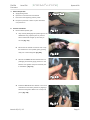
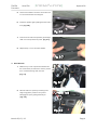
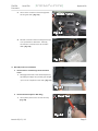
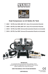
TOYOTA Scion FR-S Preparation ! ! Kit Contents: OEM Audio Plus FR-S System 400 Item 1 Item 2 Item 6 Item 7 System 400 Item 3 Item 8 Item 4 Item 5 Item 9 Item 10 ! Tools Recommended Hardware Content Item Quantity 1 2 2 1 3 1 4 1 ! Description 1” Soft Dome Tweeter with Neodymium Magnet 8” Carbon Fiber Subwoofer in Custom Fit Sealed Enclosure (with Amps Attached) Amplifier Module (See Item 2) (1) DSP Amplifier (1) Subwoofer Amplifier Quick-Sync Harness 5 1 6 7 1 1 8 1 9 1 10 1 Fuse Holder Assembly, (1) 30-Amp Fuse, (1) 20Amp Fuse ¼-20 Speed Nut Long ¼-20 Speed Nut 4mm x 1 ½” Hex Screw w/ ¼ x 1 ½ washer 4mm x 2 ½” Hex Screw w/ ¼ x 1 ½ washer Corrugated Split Loom 11 10 Cable Ties (Not pictured) Personal & Vehicle Protection Safety Goggles Seat Covers Floor Covers Protective Blanket Safety Gloves Special Tools Panel Clip Removal Socket Wrench Socket Socket Extension Wrench Screwdriver Side Cutters Allen Wrench Utility Blade Pick Tool Wire Strippers/Crimpers Heat Gun Installation Tools Masking Tape Foam Tape Cable Ties Special Chemicals Silicone Sealant Notes Notes SST # 00002-06001-01 10mm, 12mm 6” 10mm #2 Phillips 3/16” Optional for speaker grill Needed for 12g & 14g Butt Sealed-Crimp-Solder Connectors Notes 10 Piece bundle Included Notes For Sealing Grommet ! Legend STOP: Damage to the vehicle may occur. Do not proceed until process has been complied with. TOOLS & EQUIPMENT: Used in Figures to call out the specific tools and equipment recommended for the process. Issue A 06/08/12 ! ! Page | 1! TOYOTA Preparation ! Scion FR-S ! System 400 Table of Contents I. Preparation.....................................................................................................................................................1-2 1. Table Of Contents.............................................................................................................................. 2 II. Procedure...................................................................................................................................................... 3-17 1. Vehicle Preparation.......................................................................................................................... 3 2. Tweeter Installation………….............................................................................................................. 3-4 3. Radio Removal…………………............................................................................................................... 4-5 4. Quick-Sync Harness Installation................................................................................................. 5-11 5. Amplifier and Subwoofer Installation….....................................................................................12-13 6. Power Wire Installation..................................................................................................................13-14 7. Fuse Holder Assembly Installation............................................................................................ 14-15 9. Fuse Installation..................................................................................................................................15 10. Connect Battery Ground………….................................................................................................15 11. Set Clock to Correct Time….......................................................................................................15 12. Verify Radio Setting…….................................................................................................................15-17 13. Checklist / Troubleshooting.................................................................................................... 18 Accessory Installation Practice (read before installation) Care must be taken when installing this accessory to ensure damage does not occur to the vehicle. The installation of this accessory should follow approved guidelines to ensure a quality installation. These guidelines can be found in the “Accessory Installation Practices” document. This document covers such items as: • Vehicle Protection (use of covers and blankets, cleaning chemicals, etc.) • Safety (eye protection, checking torque procedure, etc.) • Vehicle Disassembly/Reassembly (panel removal, part storage, etc.) • Electrical Component Disassembly/Reassembly (battery disconnection, connector removal, etc.) Please see your Toyota/Scion/Lexus dealer for a copy of this document. Revisions and other installation assets OEM Audio Plus is committed to providing components and instructions designed for seamless integration. Please visit oemaudioplus.com for the most up to date installation related documents and media, Important Warranty Information Failure to completely and properly fill out online Warranty Registration may result in possible reduction or complete denial of future warranty claims. Complete yours today at: oemaudioplus.com/registration or call: 855 OEM-ODIO for more details and alternative methods of system registration. Issue A 06/08/12 ! ! Page | 2! TOYOTA Procedure! Scion FR-S ! System 400 1. Vehicle Preparation a. Apply parking brake. b. Open the trunk and hood of the vehicle. c. Disconnect the negative (-) battery cable. d. Prepare a protective surface to place all vehicle components on.!! ! 2. Tweeter Installation a. Remove dash speaker grills 1. Very carefully disengage the speaker grill on the dashboard using a plastic panel or pick tool. Once loosened lift straight up then away to remove. (Fig. 2-1) 2. Disconnect the tweeter connector then unclip the tweeter from the speaker grill by pushing away one of the locking tabs. (Fig. 2-2) 3. Remove the OEM Audio Plus tweeter from its packaging and carefully apply pressure to the tweeter foam gasket and push outwards prior to installation. (Fig. 2-3) 4. Install the OEM Audio Plus tweeter in the same orientation as the factory tweeter by aligning it with the locking tabs. Make sure it snaps into place. (Fig. 2-4) ! Issue A 06/01/12 ! ! ! Page | 3! TOYOTA Procedure! Scion FR-S ! System 400 5. Connect the tweeter connector and make sure it is secured with built-in locking tab. 6. Install the speaker grill by sliding the back end in first. (Fig. 2-6) 7. Push the front side of the speaker grill straight down until it snaps back into place. (Fig. 2-7) 8. Repeat steps 1-7 for the other tweeter. 3. Radio Removal 1. Make sure you have a protective blanket over the center stack/transmission area to protect from scratches during radio removal. (Fig. 3-1) 2. Remove radio trim panel by loosening outer edge using plastic panel tool or by hand. Disengage snaps by pulling towards you. (Fig. 3-2) Issue A 06/01/12 ! ! ! Page | 4! TOYOTA Procedure! Scion FR-S ! System 400 3. Use a 10mm socket to remove the (4) bolts securing the radio. (Fig. 3-3) 4. All radio connectors have a locking tab that you must push down to disconnect. Carefully remove each connector then set the radio aside. (Fig. 3-4) 4. Quick-Sync Harness Installation a. Remove Driver and Passenger Side Threshold Panel 1. Disengage both ends of the threshold panel by spreading the edges. Very carefully pull straight up to remove. Repeat for other side. (Fig. 4-1) . b. Remove Kick Panel (Driver Side Only) 1. Use a plastic panel tool to remove the snap. (Fig. 4-2) Issue A 06/01/12 ! ! ! Page | 5! TOYOTA Procedure! Scion FR-S ! System 400 2. Carefully pull the kick panel to the right towards the pedals (Two small snaps secure it). Check for green snaps that may not have came off with the kick panel. Re-insert the green snaps to the kick panel if any. (Fig. 4-3) c. Remove Driver and Passenger Side Rear Panels 1. Loosen weather-stripping by hand and remove carefully in an outward direction. (Fig. 4-4) 2. Use a 10mm socket to remove the bolt securing the bottom seat cushion. (Fig. 4-5) 3. Push down on the center of the back side of the cushion to release the locking tab then remove the bottom seat cushion. (Fig. 4-6) Issue A 06/01/12 ! ! ! Page | 6! TOYOTA Procedure! Scion FR-S System 400 ! 4. Use a plastic panel tool to remove the push in snap at the bottom of the rear panel. (Fig. 4-7) ! ! 5. Located in the trunk area, pull both backrest release straps to fold the backrest down. (Fig. 4-8) Fig.&5(9& 6. Use a plastic panel tool and remove the two push in snaps at the rear of the panel. (Fig. 4-9) 7. Carefully disengage the snaps one by one and pull the rear panel towards you and away to remove. (Check the panel for missing snaps may still be attached to vehicle). (Fig. 4-10) 8. Repeat steps 1-7 for the other side of the vehicle. Issue A 06/01/12 ! ! ! Page | 7! TOYOTA Procedure! d. Scion FR-S ! System 400 Route the Quick-Sync Harness 1. Use a utility knife and cut a U-shaped slot approximately 1” wide and 2” high in the area located in this picture on the passenger side trunk panel. This will provide access for the harness plugs to the amplifiers. (Fig. 4-11) 2. Remove the trunk carpet and trunk floor board. (Fig. 4-12) 3. Use a plastic panel tool to remove the three push in snaps securing the foam support between the back seat and spare tire. (Fig. 4-13) 4. Use a plastic panel tool and remove the push in snap on top of the factory amplifier. (Fig. 4-14) Issue A 06/01/12 ! ! ! Page | 8! TOYOTA Procedure! Scion FR-S ! System 400 5. Lift the foam support up and fold it over so it rests on top of the rear seat back rest. (Fig. 4-15) 6. Disconnect the 10-pin factory amp connector. (Fig. 4-16) 7. Run the Quick-Sync harness’ amplifier connectors through the 1”x 2” slot. Pass through one connector at a time. (Fig. 4-17) 8. Using the factory ground located behind the rear passenger side trim panel, remove the 10mm ground bolt and install the harness ground together with the factory ground. Reinstall the 10mm bolt. (Fig. 4-18) Note: Make sure harness ground terminal rests on top of the factory ground terminal. Issue A 06/01/12 ! ! ! Page | 9! TOYOTA Procedure! Scion FR-S ! System 400 9. Run the ground wire with exiting factory wire and secure using the provided cable ties. (Fig. 4-19) 10. Route the harness through the channel provided under the foam support. (This will allow the foam support to be re-installed properly). (Fig. 4-20) 11. Connect the factory male amp connector to the female connector from the Quick-Sync harness. (6-pin connector does not need to be plugged). (Fig. 4-21) 12. Re-install foam support, trunk floor board and carpet 13. Continue to route the Quick-Sync harness toward the driver side of the vehicle and secure to existing factory wires using provided cable ties. (Fig. 4-22) 14. Reinstall Driver and Passenger side trim panels and Rear seat cushions. 15. Issue A 06/01/12 ! ! ! Page | 10! TOYOTA Procedure! Scion FR-S ! System 400 16. Lift carpet by disengaging the white plastic clips in the driver side threshold area and continue routing the harness underneath the carpet towards the driver sidekick panel area. Reinstall carpet clips and weather-stripping. (Fig. 4-23) 17. Route the Quick-Sync harness under the driver side dash and towards the radio cavity. (The two yellow power wires must remain separate in the driver-side kick panel for now). Secure the harness to the existing gray factory wires using cable ties. (Fig. 4-24) 18. Route the harness towards the radio cavity until connectors are visible. (Fig. 4-25) 19. Connect the Quick-Sync harness to the factory harness and radio (10-pin and 6-pin connectors). Make sure they are fully inserted and securely locked in place. (Fig. 4-26) 20. Re-install the radio and trim panel. Issue A 06/01/12 ! ! ! Page | 11! TOYOTA Procedure! 5. Scion FR-S ! System 400 Amplifier and Subwoofer Installation a. Amplifier Connection 1. Plug the white 22-pin connector to the upper receptacle and the gray 22-pin connector to the lower receptacle of the DSP Amplifier (larger amp). Plug the black 10-pin connector to the bottom receptacle on the Sub Amplifier (smaller amp). IMPORTANT: Make sure all connectors are fully inserted and securely locked (listen for a locking click – Pull on harness lightly to confirm secure connection). (Fig. 5-1) b. Subwoofer Installation 1. Use a plastic panel tool to remove the push in snap on the passenger side of the trunk. (Fig. 5-2) 2. Install the smaller size ¼-20 speed nut on the mounting hole. (Fig. 5-3) 3. Locate the 2-hole bracket behind the passenger side trunk carpet panel. Use pliers to flatten out the bracket behind the 2-hole bracket. (Fig. 5-4) Issue A 06/01/12 ! ! ! Page | 12! TOYOTA Procedure! Scion FR-S ! System 400 4. Install and position the speed clip so that it aligns with the top hole on the 2-hole bracket. (Fig. 5-5) ! 5. Place the subwoofer enclosure in position and install the ¼-20 x 2 ½” hex screw with washer on the backside to secure the enclosure. (Shifting the enclosure may be necessary to align holes). Do not fully tighten yet. (Fig. 5-6) 6. Install the ¼-20 x 1 ½” hex screw with washer on the front side of the enclosure. (Fig. 5-7) 7. Once Subwoofer enclosure is aligned, secure by tightening both mounting screws. 6. Power Wire Installation 1. Locate the factory wiring harness grommet (on the driver side of the engine bay adjacent to the break master cylinder). Cut-off the tip of the grommet nipple. (Fig. 6-1) Issue A 06/01/12 ! ! ! Page | 13! TOYOTA Procedure! Scion FR-S ! System 400 2. Return to the driver side under-dash and route the two yellow power wires through the firewall grommet (lubricate accordingly to prevent binding). Run the entire length of power wire then pull it back one inch and apply a bead of silicone sealant to the wire. Push the wire with silicone to seal the opening. (Fig. 6-2) 3. Install the 1/4" corrugated split loom onto to the power wires. Run the entire length to the firewall grommet. (Fig. 6-3) 4. Run the loomed power wires across the engine bay towards the battery. Secure to existing factory wiring using cable ties. (Fig. 6-4) NOTE: Run the power wires directly underneath the windshield wiper cowl. 7. Fuse Holder Assembly Installation 1. Remove the 12mm top nut from the battery’s positive terminal and install fuse holder ring terminal. Re-install the 12mm nut and tighten. Note: Do not install fuses at this time! (Fig. 7-1) Issue A 06/01/12 ! ! ! Page | 14! TOYOTA Procedure! Scion FR-S System 400 ! 2. Insert 12 ga. Power Wire into Yellow butt connector. Insert 14 ga. Power Wire into Blue butt connector. Crimp and apply heat to both butt connectors to activate the solder and heat shrink insulator for the best connection possible. (Fig. 7-2) 8. Fuse Installation a. Insert the 20A fuse for the 14 ga. power wire (thinner wire) and the 30A fuse for the 12 ga. power wire. (Fig. 8-1) 9. Connect Battery ground (-). (Fig. 9-1) 10. Set Clock to correct time. 11. Verify Radio Settings. a. Pioneer Standard Radio (PT546-00120) 1. Turn radio off then press and hold "Settings" Select "Car Type" > "tC" in "Setup" (Fig. 11-1) (Pg. 52 Radio owner’s manual) NOTE: Setting Car type to FR-S will result in a balanced sound reproduction. 1. Doubl eIssue A 06/01/12 ! ! ! Page | 15! TOYOTA Procedure! Scion FR-S ! System 400 2. Select "Natural" setting in the SSP Menu. (Fig. 11-2) (Pg 9 Radio owner’s manual) b. Pioneer Premium Radio (PT546-00121) 1. Turn radio on and select "Car Type" > "tC" in "System settings" (Fig. 11-3) (Pg 57 Radio owner manual) NOTE: Setting Car type to FR-S will result in a balanced sound reproduction. 2. Select "Natural" setting in the "SSP Menu" (Fig. 11-4) (Pg. 57 Radio owner manual) c. Aisin SNS 200 (NSDA-W10U) 1. Turn radio on and select "Off" setting in the "SSP Menu" (Fig. 11-5) (Pg 187 Radio owner manual) NOTE: This setting allows the purest sound quality. Issue A 06/01/12 ! ! ! Page | 16! TOYOTA Procedure! Scion FR-S ! System 400 2. Verify "Parametric EQ" is set to "Flat" (Fig. 11-6) (Pg 185 Radio owner manual) 3. Verify the Fader/Balance settings are centered. (Fig 11-7) 4. Verify the Focus settings are centered. (Fig. 11-8) 12. This concludes the OEM Audio Plus System 400 | Scion FR-S Installation a. Start your engine. b. Turn on your radio. c. Enjoy! Issue A 06/01/12 ! ! ! Page | 17! TOYOTA Procedure! Scion FR-S ! System 400 Checklist –These points MUST be checked to ensure a quality installation.! Check: Power Windows Vehicle Function Detail: Verify power window controls are functioning properly. Power Door Locks Hazard Lights Verify power door lock controls are functioning properly. Verify hazard lights are functioning properly. Clock Verify proper time on clock. Radio Verify radio is functioning properly. Navigation (if applicable) Verify navigation system is functioning properly. Bluetooth (if Applicable) Verify Bluetooth is functioning properly. ! Basic Troubleshooting Tips In most cases, issues with the OEM Audio Plus sound system upgrade are installation related. We have found that these few simple troubleshooting steps have resolved customer issues. 1. Double-check all Amplifiers and Radio connections - Unplug each connector then re-plug to confirm secure connection. Listen and feel for the locking “click”. This is the most common issue. 2. Verify Radio Connections - Make sure that the male factory harness connectors are plugged to female OEM Audio Plus harness connectors and the male OEM Audio Plus harness connectors are plugged directly to the radio. 3. Check the fuses. 4. Check the Amplifier ground connection. 5. Reset the DSP Amplifier - Disconnect the (-) negative terminal from the battery for one hour. 6. Check the wiring – Look out for pinched or damaged wires that may have occurred during installation. 7. If all else fails - Bypass the OEM Audio Plus sound system by restoring the factory connections to the radio and contact the OEM Audio Plus technical support line at 1-855-OEM-ODIO ext. 601. Issue A 06/01/12 ! ! ! Page | 18!