1
BROADBAND
DISCONE ANTENNA
KIT
Ramsey Electronics Model No.
DA25
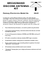
Looking for a broadband antenna with a full 360 degree
coverage? Discover what communication professionals have
known for years using a “discone” antenna. Use this antenna to
bring a multitude of signals out of the noise making it ideal for
scanners and Ultra High through Microwave Frequency
receivers! Search the airwaves for signals with this unique kit!
•
Omni directional performance, no need to point in any direction!
•
Learn about antenna theory, and what makes the discone an ideal
broadband antenna!
•
Covers all frequencies between 450 MHz and 2500 MHz, and you’ll
learn why!
•
E-Z cable connection, industry standard BNC type connector.
•
Outperforms models costing tens to hundreds of dollars more.
•
Super small in size for easy mounting almost anywhere! An ideal
“apartment” size antenna!
•
All hardware and pre-drilled metal work included.
•
“Forgiving” design gives you a high performance antenna each and
every time.
DA25 • 1
RAMSEY TRANSMITTER KITS
• FM100B Professional FM Stereo Transmitter
• FM25B Synthesized Stereo FM Transmitter
• MR6 Model Rocket Tracking Transmitter
• TV6 Television Transmitter
RAMSEY RECEIVER KITS
• FR1 FM Broadcast Receiver
• AR1 Aircraft Band Receiver
• SR1 Short wave Receiver
• SC1 Short wave Converter
RAMSEY HOBBY KITS
• SG7 Personal Speed Radar
• SS70A Speech Scrambler
• BS1 “Bullshooter” Digital Voice Storage Unit
• AVS10 Automatic Sequential Video Switcher
• WCT20 Cable Wizard Cable Tracer
• ECG1 Electrocardiogram Heart Monitor
• LC1 Inductance-Capacitance Meter
RAMSEY AMATEUR RADIO KITS
• DDF1 Doppler Direction Finder
• HR Series HF All Mode Receivers
• QRP Series HF CW Transmitters
• CW7 CW Keyer
• CPO3 Code Practice Oscillator
• QRP Power Amplifiers
RAMSEY MINI-KITS
Many other kits are available for hobby, school, Scouts and just plain FUN. New
kits are always under development. Write or call for our free Ramsey catalog.
DA25 KIT INSTRUCTION MANUAL
Ramsey Electronics publication No. MDA25 Rev 1.3
First printing: November 2001
COPYRIGHT 2001 by Ramsey Electronics, Inc. 590 Fishers Station Drive, Victor, New York
14564. All rights reserved. No portion of this publication may be copied or duplicated without the
written permission of Ramsey Electronics, Inc. Printed in the United States of America.
DA25 • 2
Ramsey Publication No. MDA25
Price $5.00
KIT ASSEMBLY
AND INSTRUCTION MANUAL FOR
BROADBAND DISCONE
ANTENNA KIT
DA25
TABLE OF CONTENTS
Introduction ................................. 4
Discone Circuit description ......... 8
Parts list...................................... 10
Assembly instructions ................. 11
Installation and Important notes .. 16
Using your DA25 ........................ 17
Troubleshooting guide ................ 17
Warranty ..................................... 19
RAMSEY ELECTRONICS, INC.
590 Fishers Station Drive
Victor, New York 14564
Phone (585) 924-4560
Fax (585) 924-4555
www.ramseykits.com
DA25 • 3
INTRODUCTION
In today’s ever growing “wireless” society, it almost seems a bit ironic that
antennas have become less and less the topic of interest in hobbyist circles.
The recent advances in wireless technology have shrunk antennas to ever
smaller an unobtrusive sizes. An example of this is the cable television industry.
They have removed the larger “traditional” antenna arrays that were once
commonplace for TV reception and replaced them with a single wire or two
entering the household. Advances in the semiconductor industry have provided
engineers with the tools to pull the smallest signals from the airwaves with
better noise performance than could have been dreamed of when the
technology of radio reception was envisioned. Advances in satellite technology
have reduced the size of a reception “dish” from over 12 feet in diameter to a 1
foot round platform!
Antenna design certainly has not made the “quantum leap” that was brought on
with the advances in the semiconductor industry, but it is just as important as it
was in those early days of radio. The original aerials, or reception antennas,
had to provide enough signal to overcome the ever present noise and allow the
early receivers to detect and demodulate signals. These early antennas were
quite large (we’ll talk a little more about this later) due to the lower frequencies
being transmitted. Again, more recent improvements have allowed us to use
higher frequencies with significantly smaller antennas.
With less and less demand for consumer antennas, the market price of these
commodities has increased. As many of us have discovered, even the lowest
cost antennas run in excess of one hundred dollars! While they are necessary if
we intend to use the antenna commercially or for television reception, it simply
is too much for a hobbyist to invest for use with a monitoring receiver. Enter the
Ramsey line of discone antennas, allowing us to “tinker” with the airwaves at an
affordable price.
Ramsey Antennas 101:
Before we break open our discone kit, lets talk about what makes an antenna
tick, and some of the terms used to define antenna performance.
How Fast are Radio Waves?
If one were to “whip” the end of a taught length of rope, you could observe the
wave created traveling down the rope to it’s end. Going back to our physics
class, recall that the speed of any object is the distance it travels divided by the
time it takes to get there, or Velocity = Distance / Time. The time a wave takes
to travel is dependant on the type of wave and the transmission medium. The
wave in our rope example can take seconds to traverse down the length of the
medium. Sound waves travel about 1100 feet every second; if we called out
DA25 • 4
before we snapped the rope, the sound waves would arrive much quicker than
the “rope wave” would. In the case of radio waves, the rate at which the waves
travel is much faster, reaching the speed of light (186,000 miles / second, or
about 3x10⁸ meters / second) in a vacuum. Radio waves do travel slightly
slower in air however. In a wire transmission line, they travel even slowly!
Frequency and Wavelength
Since all antennas collect electromagnetic waves, lets take a moment to think
about the wave motion of the radio wave itself. Try to picture a repeating
sinusoidal waveform moving down a line (oscillating). A wave that repeats itself
has a certain period (amount of time) that it takes to complete a full cycle.
Since this cycle is regular, we say that the wave has a frequency of repetition.
This frequency in fact is the reciprocal of the time it takes for the wave to
complete one full cycle, mathematically speaking f = 1 / T. By the same token
the time and frequency are related by the expression T = 1 / f.
The distance in free space that the wave takes to repeat itself is said to be the
wavelength and can be calculated using the same velocity equation. By
rearranging the velocity equation algebraically, we can say that the
Distance = Velocity x Time. Since we will approximate the velocity to be the
speed of light (“c”), once the Time is determined we can solve for the distance
traveled which is the wavelength; usually denoted as the Greek letter lambda
(“λ”) reducing our equation to λ = v x T. In English, the wavelength is equal to
the velocity multiplied by the period of the waveform. Pretty neat, huh!
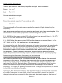
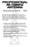
Electromagnetic Wave
One Wavelength
One Cycle
Some Amount of Time
DA25 • 5
What Are We Driving At?
Time to pull some of that theory together and get some answers:
Since: λ = v x T
And
T=1/f
We can substitute and get:
λ=v/f
Since the velocity equals “c” we wind up with:
λ=c/f
The wavelength of the radio wave equals the speed of light divided by the
frequency.
Lets plug some numbers into our equation and work out a few wavelengths. We
should notice some other properties of electromagnetic waves.
If f = 450 MHz (the wave cycles 450 million times in a second) then λ = 3x 10⁸ /
450 x 106 or .666 meters for a full wavelength.
If f = 2500 MHz (the wave cycles 2500 million times in a second) then λ = 3x
108 / 2500 x 106 or .120 meters for a full wavelength.
It’s important to note that as the frequency of a wave increases, its wavelength
decreases. Keeping in mind the introduction section where we talked about
antenna size, lets consider the “old” days of radio. The common use of low
frequencies meant much longer wavelengths and significantly larger antennas
for reception. Today's modern electronic devices tend to operate at much
higher frequencies and thereby require smaller antennas to operate properly.
Determining the Resonant Frequency of the Antenna
Let’s explore another factor in antenna as well as radio design, the resonant
frequency of the circuit. Recalling that we would like our discone antenna to
work over a large range of frequencies, we need the antenna system to be
optimized for the full desired range. Resonance in an antenna circuit occurs
when the antenna length exactly matches the wavelength of the desired
frequency. To make an antenna resonant over a range of frequencies, it needs
to look like a multitude of lengths.
Looking at the desired waveform, the shortest length of wire that will resonate
at a given frequency is one which is just long enough to permit an electric
charge to travel from one end to the other and then back again in the time of
DA25 • 6
one radio frequency (or RF) cycle. Since the charge traverses the wire twice,
the length of wire needed to permit the charge to travel the total distance in
one cycle is λ / 2, or one half the wavelength. Therefore, the shortest resonant
wire length will be one half wavelength long.
Let’s consider a “half wavelength” example to help it make sense. Picture a
trough with barriers at each end. If a rubber ball is rolled along the trough from
one end to the other it will hit the end and bounce back. When it bounces
back, it will hit the near barrier and bounce again. This will continue until the
ball runs out of energy and stops. If however, whenever the ball returns to the
near barrier it is given a push just as it starts away, its back and forth motion
can be kept up indefinitely as long as the impulses are timed properly. In other
words, the rate or frequency of the impulses must be adjusted to the length of
travel and the rate of travel. If the timing of the impulses (the push) and the
speed of the ball are fixed, the length of the trough must be adjusted to “fit”. In
the case of the antenna, the speed is constant. This leaves the alternatives of
adjusting the frequency or the length of wire to match a given frequency.
Antenna Gain
Another performance specification common with
antennas is their gain, usually given in dBi units. To
understand this concept, let’s explore the “i” in the dBi
unit as an isotropic source. Imagine a point in space as
a source of a radiating signal. The signal would then
expand spherically from the point source. If we then
move a given distance from the point source, the power
would be distributed uniformly in all directions. The
power density is uniform about an isotropic source and
thus is related to the surface area of a sphere (area =
4x π x radius 2). Although this is not practically
possible, it is the basis for an antenna gain specification. The gain of an
antenna is usually referenced in comparison to this type of source in a decibel
unit with a logarithmic relationship. Without getting hung up too much on
logarithmic theory, suffice it to say that an increase of 3 dB is equal to twice
the power being present . An increase of 10 dB is equivalent to a gain factor of
10. For example, a 1 Watt signal with a gain of 3 dB equals two Watts, while
the same power with 10 dB gain is 10 Watts.
Although we are using our discone as a receiving antenna, the rules of
antenna gain are reciprocal so we can count on at least a 3 dBi improvement
in the signal power over the entire frequency range.
DA25 • 7
What About Impedance Matching and VSWR ?
Another consideration with electromagnetic wave antennas is the “match”
presented to either the receiver or transmitter. In our discussion of wavelength
and resonant frequencies it became apparent that the length of the antenna is
critical to match that of the desired frequency. A small error in length can
detune an antenna significantly and inhibit the antennas performance.
For many communications systems, 50 or 75 Ohms are the desired “magical”
impedance values desired for the antenna systems. The proper impedance
allows for maximum power to transfer to or from the antenna system with a
minimum of loss. Even with the high frequencies being used we want the
antenna to appear as a proper load. In this way the antenna presents a good
match to the receiver. Luckily for us, the discone antenna exhibits exceptional
performance in the impedance matching department.
The Voltage Standing Wave Ratio (VSWR) of an antenna system is another
measure of this impedance match. At RF frequencies, if the load at the end of
the transmission line is not the desired impedance, the signal will actually
reflect back down the line and precipitate a high VSWR. Typical usable VSWR
ratios are in the “3.0 : 1.0” range for commercial available communications
equipment, while the robust discone design actually outperforms these at
many frequencies with a typical ratio of “1.5 : 1.0” or better. A “1.0 : 1.0” ratio
indicates the best match possible resulting in no wasted signal reflection.
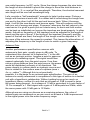
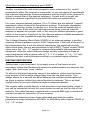
DISCONE DESCRIPTION
Getting back to the kit at hand, let us apply some of the theory we just
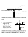
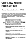
discussed. Notice that the discone antenna is predominately two sections, the
upper “disk” and lower “cone” section.
To allow for the large frequency range of the antenna, notice how the lower
cone section of the antenna slopes away from the top disk section. This
design allows for a smooth transition between the multiple wavelengths that
we hope to receive without any discontinuities in between. This is an ideal
configuration for an omni-directional antenna response pattern.
The coaxial cable mounts directly to the provided circuit board plate, which in
turn will be connected to both the conic section as well as the top disk of the
antenna. The cable has been supplied with a crimped BNC type connector at
one end for ease of connection to your receiver.
The discone dimensions have been calculated such that the usable
performance range is between 450 MHz to 2500 MHz with a typical VSWR of
“2.0 : 1.0” or less.
DA25 • 8
Disk
Coaxial Cable Center Conductor
Coaxial Cable Shield
Cone
Mounting Pipe
Coaxial Cable
Ramsey offers two models of this particular antenna, one with no active
components and the other with a low noise preamplifier to further boost the
antenna gain.
The DA25 kit which you are about to assemble is the non-preamplified
version. The advantages to this particular model are its ease of use (no
external power required) and the fact that it can just as easily be used as a
transmit antenna as well. Experimenters have used this particular design for a
host of transmit applications including increasing the distance of their PC’s
wireless LAN to boosting the range of cordless phones.
However, if your particular application is for reception only, and power is not
an obstacle, you may decide to “upgrade” to the preamplified version of this
kit, the DAP25. The good news is, if you have not begun assembly, you may
return your kit for full credit towards the amplified version.
DA25 • 9
PARTS SUPPLIED WITH YOUR DA25 KIT
1
1
3
3
3
1
1
1
3 Qt. funnel “cone”
7 inch pie-plate (CAUTION, EDGES MAY BE SHARP!)
#6 – 32 x 1/4” screws
#6 – 32 M-F stand-offs
#6 – 32 nuts
DCA2 circuit board
PVC coupling
3’ BNC cable
RAMSEY "Learn-As-You-Build” KIT ASSEMBLY
There are solder connections on the DA25 printed circuit board. Therefore,
PLEASE take us seriously when we say that good soldering is essential to the
proper operation of your discone antenna kit!
•
•
•
Use a 25-watt soldering pencil with a clean, sharp tip.
Use only rosin-core solder intended for electronics use.
Use bright lighting; a magnifying lamp or bench-style magnifier may
be helpful.
We have a two-fold strategy for the order of the following kit assembly steps.
First, we install parts in physical relationship to each other, so there's minimal
chance of inserting wires into wrong holes. Second, whenever possible, we
install in an order that fits our "Learn-As-You Build" Kit building philosophy.
This entails describing the circuit that you are building, instead of just blindly
installing components. We hope that this will not only make assembly of our
kits easier, but help you to understand the circuit you’re constructing.
For each part, our word "Install" always means these steps:
1. Pick the correct component with the proper value to start with.
2. Insert it into the correct PC board location.
3. Orient it correctly, following the PC board drawing and the written
directions for all parts - especially when there's a right way
and a wrong way to solder it in.
4. Solder all connections unless directed otherwise. Use enough heat
and solder flow for clean, shiny, completed connections.
5. Trim or nip the excess component lead wire after soldering.
DA25 • 10
DA25 DISCONE ANTENNA KIT ASSEMBLY
Although we know that you are anxious to complete the assembly of your antenna kit, it is necessary to assemble it in a specific order to insure the proper
operation of the finished unit. Try to avoid the urge to jump ahead installing
components.
Since you may appreciate some warm-up soldering practice as well as a
chance to put some landmarks on the PC board, we’ll first install some of the
larger mounting components. This will also help us to get acquainted with the
up-down, left-right orientation of the circuit board (can you do that with a circular board?). Look carefully at the component layout diagrams in the manual to
help with your assembly.
Use the boxes to check off your progress.
Check all received parts against the parts list. The parts list describes the various markings that may be found on the kit parts. Carefully sort the parts into
small piles, (an empty egg tray does nicely for this purpose) to aid in finding the
correct part at the required time.
Enough of that… lets get started!
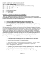
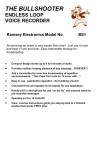
First we will prepare the coaxial cable for its installation to the circuit board. We
need to “break out” the two wire components of the cable. Trim about 3” of the
outer insulation from the cable, being careful not to cut through the outer braid
of wire. Using a fine pointed tool, carefully “un-braid” about 2 1/4” of the outer
conductor and fan out the loose strands of wire. Once this is accomplished, trim
back about 2” of the center insulation. Be careful not to cut through the center
conductor. You will want to trim about 1 1/2” off of the exposed braid to aid with
further installation.
3 inches
Braid
Coaxial Cable
Center Conductor
2 inches
Center Insulation
DA25 • 11
1. Carefully “tin” the center conductor of the cable by adding a small
amount of solder to the twisted center conductor. Use care not to leave
the soldering iron in contact with the wire for too long as it can melt the
center insulation. Tinning allows us easier installation of the coaxial cable
to the circuit board assembly and minimizes the chance of overheating the
wire when this installation occurs. Have a look at the diagram to see what
the complete “pre-assembled” cable should look like.
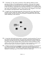
2. Inspect the circuit board assembly. Notice that the “top” side of the assembly is blank, while the “bottom” side is almost completely filled with
tinned copper. We will use this circuit board to transition form the coaxial
cable assembly to the antenna.
3. Insert the full length tinned center conductor wire through the P1 hole in
the center of the circuit board. This wire will connect the circuit board assembly to the disk section of the antenna and will also connect to the center conductor of the coaxial cable. Push until the center insulation of the
cable is almost flush with the circuit board. Leave enough of a gap to solder the tinned center conductor in place from the bottom side.
4. Gently spread the trimmed braid to the area immediately around the P1
hole. Be sure that the braid ONLY contacts the tinned copper ground
plane area around P1. Trim off any stray wires that may short circuit to the
adjacent mounting rings or the center conductor solder pad.
DA25 • 12
Solder Here
Bottom (Copper Plated) side
Solder Here
Coaxial Cable
Now we are getting somewhere! All your careful preparation will pay dividends
as we install the coax cable to the circuit board. We did this first as it can be
quite difficult to perform this operation once the circuit board is installed on to
the cone.
5. Using the 3 #6-32 screws
provided, insert them
through the circuit board assembly as shown. Fasten
the screws into place using
the #6-32 stand-offs provided. Be careful not to
over-tighten the nylon parts
or they may shear off.
Bottom
(Copper Plated) side
Coaxial Cable
Now we are getting to probably the most difficult solder connection of the entire
antenna kit! We will solder the circuit board assembly to the funnel cone. This
may take considerably more heat than a single 25 watt iron can provide, you
may wish to use two irons or an additional heat source to speed things up.
DA25 • 13
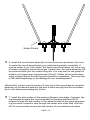
Solder Points
6. Install the circuit board assembly to the funnel cone as shown. Use care
to center the circuit board before you solder the assembly completely. It
may be easier if you “tack solder” the board into place before you run a ring
of solder completely around the board. Careful now, the entire assembly will
be quite hot while you are constructing this. You may want to use gloves to
protect your fingers from being burned (Ouch!!). Solder all the connections
using enough heat to flow the ground connection completely. This may take
a little while depending on the wattage of your soldering pencil.
Whew! Well, we are over the worst of it now, just a few more steps to complete
assembly of the discone antenna. Be sure to allow enough time for the assembly to cool before proceeding any further.
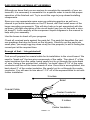
7. Install the disk section of the antenna (flanged outer edge, if present, facing downward toward the cone assembly) by passing the three #6-32
screws through the disk section of the antenna while at the same time passing the center conductor wire through the center hole of the disk. With the
#6-32 nuts provided, secure the disk section of your antenna into place.
DA25 • 14
Solder Here
8. Solder the center conductor wire into place on the disk section of the antenna. Trim off any excess lead that is protruding from the disk. Have a look
at the above diagram to help out if necessary.
CONGRATULATIONS !
Your discone antenna is now complete! Have a final look over your work,
paying particular attention to the solder connections. Remember that any
problems you find now can save time and effort after the unit has been
mounted.
DA25 • 15
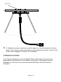
Glue Here
INSTALLATION OF THE ANTENNA MOUNT
When you are satisfied that your solder connections are “just right”, we will
install the PVC antenna mast coupler included with the kit. The mast mounting
is a 1” PVC coupler. We recommend that you glue the coupling into place with
some RTV or contact cement. Be sure to fit the coupler firmly into place after
threading the cable assembly through it. If the glue sets up with the coupling in
a little tilted, you will forever see a slightly “off balance” discone.
IMPORTANT NOTE CONCERNING OUTDOOR USAGE
Many of the metal components contained in your discone antenna will oxidize
and rust if left exposed to direct weather. It is recommended that if you are
planning on permanently mounting the antenna outdoors you coat the entire
unit with an enamel paint before installing.
DA25 • 16
USING YOUR DA25 DISCONE ANTENNA
Now we are ready for the moment of truth, the running of your discone antenna. Were pretty sure by now you have a place selected to install it, you can
use a couple of nylon wire ties and a bit of 1” PVC pipe to fasten it into place.
A fairly good “poor mans” test is to search on your scanner or radio receiver
for a weak station, one that is barely breaking the threshold of your receivers
sensitivity. Note your signal strength indication of the station, and proceed to
disconnect your existing antenna and replace it with your DA25. If your like
our many satisfied customers, your notice a significant improvement in signal
quality. Try this test on several frequencies throughout the band, and find out
just how poorly your original antenna was working!
TROUBLESHOOTING GUIDE
If your DA25 does not work at all, re-check the following:
•
Correct connection of the soldered coaxial cable ends. Sometimes the action of installing the PVC pipe stresses the wire and can cause a break.
•
Is that disk on the top soldered to the feed through wire? Make sure that
the wire hasn’t folded under the disk and shorted by touching the ground
connections somewhere.
•
all solder connections
Still having trouble? While we had hoped that it wouldn’t come to this, if you
are still having trouble with your DA25 here are a few additional suggestions.
Use a methodical, logical troubleshooting technique. Most problems can be
solved using common sense. A volt-ohm meter and a clear head are usually
all that are needed to correct any problem. Most problems are due to
misplaced parts and/or bad solder connections. Working backwards through
the assembly steps will often lead you to the problem. Re-visit the extensive
theory of operation include in this manual, and try to apply to your specific
problem.
Have another set of eyes look through your work. Here at the shop we have
often run into a “stone wall” of a problem only to have a fellow technician see
our obvious error. It is sometimes very difficult to see your own mistake, taking
a break can often solve this common problem.
Make sure that you have “checked” all the assembly steps boxes, you may
have forgotten one or two of them.
Please understand that it is nearly impossible to “troubleshoot” by phone, any
specific questions should be documented and sent to us by mail.
DA25 • 17
CONCLUSION
We sincerely hope that you enjoy the use of this Ramsey product. As always,
we have tried to compose our manual in the easiest, most user-friendly format
that is possible. As our customers, we value your opinions, comments, and
additions that you would like to see in future publications. Please submit
comments or ideas to:
Ramsey Electronics Inc.
Attn. Hobby Kit Department
590 Fishers Station Drive
Victor, NY 14564
Please also feel free to visit our Website at www.ramseyelectronics.com and
offer your observations to other kit enthusiasts as well.
And once again, thanks from the folks at Ramsey!
DA25 • 18
The Ramsey Kit Warranty
Please read carefully BEFORE calling or writing in about your kit. Most problems can be
solved without contacting the factory.
Notice that this is not a "fine print" warranty. We want you to understand your rights and ours too!
All Ramsey kits will work if assembled properly. The very fact that your kit includes this new manual
is your assurance that a team of knowledgeable people have field-tested several "copies" of this kit
straight from the Ramsey Inventory. If you need help, please read through your manual carefully.
All information required to properly build and test your kit is contained within the pages!
1. DEFECTIVE PARTS: It's always easy to blame a part for a problem in your kit, Before you
conclude that a part may be bad, thoroughly check your work. Today's semiconductors and passive
components have reached incredibly high reliability levels, and it’s sad to say that our human
construction skills have not! But on rare occasions a sour component can slip through. All our kit
parts carry the Ramsey Electronics Warranty that they are free from defects for a full ninety (90)
days from the date of purchase. Defective parts will be replaced promptly at our expense. If you
suspect any part to be defective, please mail it to our factory for testing and replacement. Please
send only the defective part(s), not the entire kit. The part(s) MUST be returned to us in suitable
condition for testing. Please be aware that testing can usually determine if the part was truly
defective or damaged by assembly or usage. Don't be afraid of telling us that you 'blew-it', we're all
human and in most cases, replacement parts are very reasonably priced.
2. MISSING PARTS: Before assuming a part value is incorrect, check the parts listing carefully to
see if it is a critical value such as a specific coil or IC, or whether a RANGE of values is suitable
(such as "100 to 500 uF"). Often times, common sense will solve a mysterious missing part
problem. If you're missing five 10K ohm resistors and received five extra 1K resistors, you can
pretty much be assured that the '1K ohm' resistors are actually the 'missing' 10 K parts ("Hum-m-m,
I guess the 'red' band really does look orange!") Ramsey Electronics project kits are packed with
pride in the USA. If you believe we packed an incorrect part or omitted a part clearly indicated in
your assembly manual as supplied with the basic kit by Ramsey, please write or call us with
information on the part you need and proof of kit purchase.
3. FACTORY REPAIR OF ASSEMBLED KITS:
To qualify for Ramsey Electronics factory repair, kits MUST:
1. NOT be assembled with acid core solder or flux.
2. NOT be modified in any manner.
3. BE returned in fully-assembled form, not partially assembled.
4. BE accompanied by the proper repair fee. No repair will be undertaken until we have received
the MINIMUM repair fee (1/2 hour labor) of $25.00, or authorization to charge it to your
credit card account.
5. INCLUDE a description of the problem and legible return address. DO NOT send a separate
letter; include all correspondence with the unit. Please do not include your own hardware
such as non-Ramsey cabinets, knobs, cables, external battery packs and the like. Ramsey
Electronics, Inc., reserves the right to refuse repair on ANY item in which we find excessive
problems or damage due to construction methods. To assist customers in such situations,
Ramsey Electronics, Inc., reserves the right to solve their needs on a case-by-case basis.
The repair is $50.00 per hour, regardless of the cost of the kit. Please understand that our
technicians are not volunteers and that set-up, testing, diagnosis, repair and repacking and
paperwork can take nearly an hour of paid employee time on even a simple kit. Of course, if we find
that a part was defective in manufacture, there will be no charge to repair your kit (But please
realize that our technicians know the difference between a defective part and parts burned out or
damaged through improper use or assembly).
4. REFUNDS: You are given ten (10) days to examine our products. If you are not satisfied, you
may return your unassembled kit with all the parts and instructions and proof of purchase to the
factory for a full refund. The return package should be packed securely. Insurance is
recommended. Please do not cause needless delays, read all information carefully.
DA25 • 19
DA25 DISCONE ANTENNA KIT
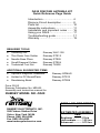
Quick Reference Page Guide
Introduction ...................................... 4
Discone Circuit description ............... 8
Parts list ........................................... 10
Assembly instructions ...................... 11
Installation and Important notes ....... 16
Using your DA25 .............................. 17
Troubleshooting guide ...................... 17
Warranty .......................................... 19
REQUIRED TOOLS
• Soldering Iron
• Thin Rosin Core Solder
• Needle Nose Pliers
• Small Diagonal Cutters
• Technician Tool Set
Ramsey WLC-100
Ramsey RTS12
Ramsey RTS05
Ramsey RTS04
Ramsey TK405
ADDITIONAL SUGGESTED ITEMS
Optivisor Magnifier Headband
Holder for PC Board/Parts
Desoldering Braid
•
•
•
Ramsey OPMAG
Ramsey RTS13
Ramsey RTS08
Price: $5.00
Ramsey Publication No. MDA25
Assembly and Instruction manual for:
RAMSEY MODEL NO. DA25
TOTAL SOLDER POINTS
4
RAMSEY ELECTRONICS, INC.
590 Fishers Station Drive
Victor, New York 14564
Phone (585) 924-4560
Fax (585) 924-4555
www.ramseyelectronics.com
ESTIMATED ASSEMBLY
TIME
Beginner ............2 hrs
DA25 • 20
Intermediate......... 1.25 hrs
Advanced ............. 0.75 hrs