1
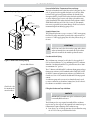
vii - near boiler piping
2. Excess water should go through the overflow and out through
the condensate drain line. Verify proper operation of the drain
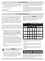
must be installed so the chiller medium is piped in parallel with the
boiler with appropriate valves to prevent the chilled medium from
entering the boiler.
The boiler piping system of a hot water boiler connected to heating
coils located in air handling units where they may be exposed to refrigerated air circulation must be equipped with flow control valves
or other automatic means to prevent gravity circulation of the boiler
water during cooling cycle.
line (or external condensate pump if used).
3. Reinstall the vent drain line.
Chilled Water Piping
The boiler, when used in connection with a refrigeration system,
VIII - Combustion Air And Vent Pipe
Connections & Terminations
For boilers connected to gas vents or chimneys, vent installations
shall be in accordance with Venting Requirements of the National
Fuel Gas Code, ANSI Z223.1-latest revision, CSA-B149.1 and
B149.2, and applicable provisions of the local building codes.
Provisions for combustion and ventilation air must be in accordance
with the National Fuel Gas Code, ANSI Z223.1-latest revision, CSAB149.1 and B149.2, or applicable provisions of the local building
code.
These boilers require a dedicated direct vent system. All air for combustion is taken directly from outdoors through the combustion air
intake pipe. All flue products are discharged to the outdoors through
the vent pipe. Insulate lengths of combustion pipe in unconditioned
areas.
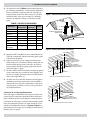
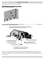
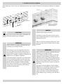
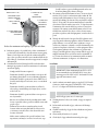
1. See Figures 1 through 5 for combustion air and vent pipe
roof and sidewall termination (roof termination is preferred).
Combustion air and vent pipes must terminate together in
same atmospheric pressure zone as shown. Construction through which vent and air intake pipes may be installed is
a maximum 24” and a minimum ¼” thickness.
2. Combustion air and vent pipe fittings must conform to
American National Standards Institute (ANSI) standards and
American Society for Testing and Materials (ASTM) standards
D1784 (schedule-40 CPVC), D1785 (schedule-40 PVC), D2665
(PVC-DWV), D2241 (SDR-21 and SDR-26 PVC), D2661 (ABSDWV), or F628 (schedule-40 ABS). Pipe cement and primer
must conform to ASTM standards D2564 (PVC) or D2235
(ABS).
3. For Canadian installations all plastic venting material must be
listed to ULC S636.
!
NOTICE
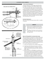
NOTE: The exhaust transition from 2” pipe to 3” pipe
must be made in a vertical run. Transition pieces are not
included. (See Figure 8 for details.)
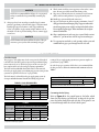
Combustion and Vent Piping Length
Table #4
Material
Maximum Allowable Temperatures
Of Typical Non-Metallic Vet Material
HDT
RTI
Standard
°F
°C
°F
°C
PVC
158
70
–
–
ASTM F 891 *
ASTM D2665 **
ASTM D1785 **
ASTM D2241 **
CPVC
210
100
–
–
ASTM D2846 **
ASTM F441 **
ASTM F442 **
ABS
180
82
–
–
ASTM D2661 ***
ASTM F628 ***
RadelA200
414
212
–
–
UL-1738
ULC S636
* Allowable temperatures based on Classifications covered in
ASTM D4396 [Deflection Temperatures under Load (264psi)
(1819 KPa)].
** Allowable temperatures based on Classifications covered in
ASTM D1784 [Deflection Temperatures under Load (264psi)
(1819 KPa)].
*** Allowable temperatures based on Classifications covered in
AsTM D3965 [Deflection Temperatures under Load(264psi)
(1819 KPa)].
WARNING
Do not use cellular core PVC for venting flue gas.
4. Combustion air and vent pipe connections on boiler are 2” but
must increase to 3”. Due to potential for flue gas temperatures
above 155°F, the first 30” of supplied vent pipe is CPVC while
the remaining vent pipe can be PVC. Any replacement of the
first 30” of vent pipe must be made with CPVC.
3” Pipe Min. Venting
3” Pipe Max. Venting
15 ft. equivalent length
100 ft. equivalent length
The length of pipe is counted from the end of the supplied 2” CPVC
pipe exiting the boiler. The termination is not counted in the “Total
Equipment Length.” The combustion air supply pipe must terminate
at the same location as the exhaust pipe.
12