1
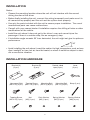
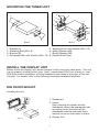
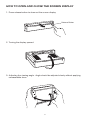
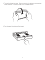
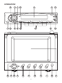
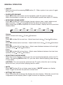
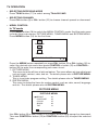
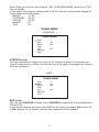
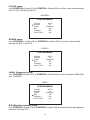
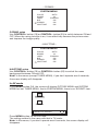
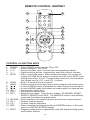
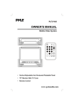
PLPK5TVD
OWNER’S MANUAL
COLOUR LCD TV/RECEIVER
INSTALLATION
Notes:
• Choose the mounting location where the unit will not interfere with the normal
driving function of the driver.
• Before finally installing the unit, connect the wiring temporarily and make sure it is
all connected up properly and the unit and the system work properly.
• Use only the parts included with the unit to ensure proper installation. The use of
unauthorized parts can cause malfunctions.
• Consult with your nearest dealer if installation requires the drilling of holes or other
modifications of the vehicle.
• Install the unit where it does not get in the driver’s way and cannot injure the
passenger if there is a sudden stop, like an emergency stop.
• If installation angle exceeds 30˚ from horizontal, the unit might not give its optimum
performance.
30˚
• Avoid installing the unit where it would be subject to high temperature, such as from
direct sunlight, or from hot air, from the heater, or where it would be subject to dust,
dirt or excessive vibration.
INSTALLATION HARDWARE
Bracket (A)
(2 pcs)
Hexagonal Bolt
(M6 x 12) (4 pcs)
Tapping Screw
(M5 x 25) (1 pcs)
Bracket (B)
(2 pcs)
Tapping Screw
(M5 x 12) (4 pcs)
Nut
(M5) (1 pcs)
Double sided
tape (2 pcs)
Mounting Bolt
(M5 x 5) (8 pcs)
Plain Washer
(M5) (1 pcs)
2
Mounting Bolt
(M4 x 5) (4 pcs)
Spring Washer
(M5) (5 pcs)
Lever
(2 pcs)
Strap (1 pcs)
Spring Washer
(M6) (4 pcs)
MOUNTING THE TUNER UNIT
4
2
6
6
5
4
7
1
6
3
1
8
5
7
5
7
3
8
2
Step 1
1.
2.
3.
4.
Step 2
Bracket (A)
Mounting Bolt (M5 x 5)
Bracket (B)
Hexagonal Bolt with Washer (M6 x 12)
5.
6.
7.
8.
Tapping Screw with Washer (M5 x 12)
Spring Washer (M6)
Spring Washer (M5)
Double Sided Tape
INSTALL THE DISPLAY UNIT
Before install the display unit, please remove its tail screw and cable parts. This unit
can be properly installed either from “front” (convertional DIN Front-mount) or “rear”
(DIN Rear-mount installation, utilizing threaded screw holes at the sides of the unit
chassis). For details, refer to the following illustrated installation methods.
DIN FRONT-MOUNT
Installing the unit
1
1. Dashboard
2
182
53
3
(Fig. 1)
2. Holder
After inserting the holder into the
dashboard, select the appropriate tab
according to the thickness of the
dashboard material and bend them
inwards to secure the holder in place.
3. Display Unit
3
1. Dashboard
1
2. Nut (M5)
6
4
3. Spring Washer
4. Tapping Screw with Washer (M5 x 25)
2
7
5. Screw
5
3
6. Plain Washer
7. Strap
Be sure to use the strap to secure the
back of the unit in place. The strap can
be bent by hand to the desired angle.
(Fig. 2)
Removing the unit
1
1. Lever
Insert the levers supplied with the unit
into the grooves at both sides of the unit
as shown in figure until they click.
Pulling the levers upward and out to
makes it possible to remove the unit.
DIN REAR-MOUNT
Installation using the screw holes on the both sides of the unit.
1
Fastening the unit to the factory radio
mounting bracket.
2
5
4
2
3
1. Select a position where the screw holes
of the bracket and the screw holes of
the main unit become aligned (are fitted),
and tighten the screws at 2 places on
each side.
Use either truss screws (5 x 6mm) or
screws (4 x 6mm), depending on the
shape of the screw holes in the bracket.
2. Screw
5
3. Factory Radio Mounting Bracket
4. Dashboard or Console
5. Hook and Screw (Remove this part)
Note: The frame, strap, and half-sleeve are
not used for REAR-MOUNT.
4
HOW TO OPEN AND CLOSE THE SCREEN DISPLAY
1. Press release button to draw out the screen display.
Release Button
2. Turning the display upward.
3. Adjusting the viewing angle. Angle should be adjusted slowly without applying
unreasonable force.
5
4. Turning the display downward. Make sure to return the display to centre position
before drawing in. It cannot be draw in with its angles adjusted.
5. Push the panel, the display will be drawn in.
6
FRONT
Lch SPK
FRONT
Rch SPK
REAR
Lch SPK
REAR
Rch SPK
VIOLET
WHITE/BLACK
WHITE
GREY/BLACK
GREY
GREEN/BLACK
GREEN
VIOLET/BLACK
GREY/BLACK
GREY
CHOKE
BOX
TV CONTROL
7
Lch WHITE
Rch RED
Lch WHITE
(FOR RCA LINE VERSION ONLY)
REAR RCA CABLE
FRONT RCA CABLE
GREY PLUG
BLACK PLUG
AV1
BLACK/GREY CABLE
AV INPUT
BLACK CABLE
RADIO/TV MAIN UNIT
(VIEW FROM REAR)
FROM VIDEO/AUDIO SOURCE
VIDEO OUTPUT
75ohm RF WIRE (BLACK)
(GREY)
(BROWN)
RADIO ANTENNA INPUT
TV DIVERSITY ANTENNA INPUT
Rch RED
BLACK GROUND
YELLOW MEMORY
RED ACC
BLUE/WHITE POWANT
ELECTRICAL CONNECTION
RADIO/TV MAIN UNIT
(VIEW FROM FRONT)
TV DIVERSITY ANTENNA INPUT
TV MONITOR
AV2
VIDEO AUDIO–R AUDIO–L
RADIO CONTROL
DISPLAY UNIT
TO POWER SUPPLY
RADIO CONTROL
TV MONITOR
OPERATION
16
11
7 24
1
5
6
8
19
10 20
9
4
12
2
15
18
21
22
8
3
17
1
13
14
23
4
GENERAL OPERATION
• ON/OFF
Switch on the unit by pressing PWR button (1). When system is on, press it again
to turn it off.
• FACEPLATE RELEASE
Press REL button (2) to draw out the faceplate, push the panel to draw in.
When the faceplate is drawn out, turn the faceplate upward and adjust TV display.
• SELECTING SOUND MODE
Press SEL button (6) to move display through volume, bass, treble, balance and
fader functions. Use (7) and (8) buttons to adjust the selected mode.
When mode has not been adjusted for several seconds, display returns to previous
display status.
VOL
(Volume)
Volume
Adjust volume level using
BAS
(Bass)
(7) and
TRE
(Treble)
BAL
(Balance)
FAD
(Fader)
(8) buttons.
Bass
Press SEL button (6) for one time. Adjust bass level using
Treble
Press SEL button (6) for two times. Adjust treble level using
(7) and
(7) and
(8) buttons.
(8) buttons.
Balance
Press SEL button (6) for three times. Adjust sound balance between left and right
speakers using (7) and (8) buttons.
Fader
Press SEL button (6) for four times. Adjust sound balance between front and rear
speakers using (7) and (8) buttons.
• SELECTING PLAYING MODE
When the screen display is drawn out, the unit would automatically switch into TV
mode. By pressing MOD button (12), you can select desired playing mode among
TV and radio.
CAUTION: The unit cannot be switched into TV mode, when the car is running.
So at this time, you just select playing mode in radio.
• MUTE
Press MUT button (3) to cut down sound output, “MUTE” appears on display.
Press it again to resume the previous volume level.
• SETTING THE CLOCK
Press T/F button (5) to change the display into clock display. While the current time
is appeared on the display, press it again to return to frequency showing.
9
Time Setting
- Set hours:
Holding down T/F button (5) for several seconds, and the clock is blinking on the
display, press
button (14) to adjust the hour.
- Set minutes:
Holding down T/F button (5) for several seconds, and the clock is blinking on the
display, press
button (13) to adjust the minutes.
• LIQUID CRYSTAL DISPLAY
The LCD (4) can show the current state of the unit.
• RESET
Reset button (24) must be activated with either a ball-point pen or thin metal object.
The reset button is to be activated for the following reasons:
- Initial installation of the unit when all wiring is completed.
- All the function buttons do not operate.
- Error symbol on the display.
10
RADIO OPERATION
• SELECTING BAND
Press BAND button (11) to change between three FM bands and two AM bands.
Each band stores up to six preset stations.
FM1
FM2
FM3
AM1
AM2
• SELECTING STATION
During radio mode, press MAN/SKP button
(13) to increase frequency or
(14)
to decrease frequency by one step of channel spacing. Hold the button longer for
fast tuning. The frequency is updated correspondingly on display.
• SELECTING MEMORY
Press preset memory buttons (15) to preset stations at tuner mode. With this
system, a total of 30 stations can be stored in the memory of six buttons.
The stations might be FM1, FM2, FM3, AM1 and AM2 band. The operation is as
below:
- Store in Memory
Press and hold desired memory location button for several seconds. The current
listening station will be stored into the number button.
- Retrieve a Preset Station
Press any one of the buttons (15) to retrieve a station which had been stored in
the memory in advance the chosen number is shown on display.
• AUTO MEMORY STORING & SCANNING
- Auto Memory Scanning
Check the stations stored in the preset memories.
Press to retrieve automatically the current stations stored in six preset memories
and it will display for several seconds. Press either the AS/PS button (16) again
or anyone of the memory buttons to stop the scan operation. During the preset
scan operation, the channel number flashes on the display for several seconds.
Preset station scan continuously in the pre-selected band.
- Auto Memory Storing
Seeks the six strongest stations in the pre-selected band automatically and stores
the stations automatically in preset memories.
Initially the tuner seeks and memories the stations in local mode until 6 stations
are fully occupied. Otherwise, seeking is proceeded in distance mode.
11
TV OPERATION
• SELECTING RECEIVING MODE
Press TV/AV button (17) to select among TVch/AV1/AV2.
• SELECTING CHANNEL
Press CH+ button (9) or CH– button (10) to choose channel upward or downward
• MENU CONTROL
In TV mode
Press MENU button (18) to switch the MENU CONTROL mode. And the main menu
includes three sub-menus: PICTURE MENU, TUNER MENU and SYSTEM MENU.
Press MENU button (18) for the first time:
PICTURE
TUNE
SYSTEM
MENU PIC ADJUST
Press the MENU button repeatedly or press CH+ button (9) or CH– button (10) to
select the desired sub-menu then press CONTROL+ button (19) or CONTROL–
button (20) to enter the corresponding sub-menu to set.
1. PICTURE MENU
This menu includes all item of picture feature. The menu allows picture adjustment
such as bright, contrast, color, and etc. The details please refer to PICTURE MENU.
2. TUNER MENU
This is to activate program setting. The details please refer to TUNER MENU.
3. SYSTEM MENU
This menu includes the items for system control, such as color, sound, language,
and etc. The details please refer to SYSTEM MENU.
PICTURE MENU
PICTURE MENU
BRIGHT
CONTRAST
COLOR
SHARP
TINT
20
25
45
63
10
Use CH+ button (9) or CH– button (10) to select picture mode upward or downward.
Then use CONTROL+ button (19) or CONTROL–button (20) to adjust the selected
item.
12
Note: When you set the color mode to “PAL” in SYSTEM MENU, there is no “TINT”
item to display.
In this menu, the range of setting value is 00~63, and the recommended range of
these values are listed below:
BRIGHT:
10~32
CONTRAST: 20~40
COLOR:
40~50
SHARP:
63
TINT:
10
TUNER MENU
--POSITION -TUNER MENU
POS
SKIP
BAND
FINE
AFT
SEARCH
ASM
1
ON
UHF
OFF
POSITION setup
You can use numeric buttons to input the TV channel number. For example, you
input 8, when you turn off the unit and then turn it on again, the program of channel
8 will be displayed.
--SKIP-TUNER MENU
POS
SKIP
BAND
FINE
AFT
SEARCH
ASM
1
ON
UHF
OFF
SKIP setup
You can use CONTROL+ button (19) or CONTROL– button (20) to switch between
ON and OFF.
If you set the position to 8 and select SKIP to ON, when you press CH+ button (9)
or CH– button (10) to choose channel, the channel 8 will be skipped.
13
--BAND-TUNER MENU
POS
SKIP
BAND
FINE
AFT
SEARCH
ASM
1
ON
UHF
OFF
BAND setup
You can use CONTROL+ button (19) or CONTROL– button (20) to switch between
UHF, VHFL and VHFH band.
--FINE-TUNER MENU
POS
SKIP
BAND
FINE
AFT
SEARCH
ASM
1
ON
UHF
OFF
FINE setup
When the frequency has warp, and the picture displayed unstable, you can use
CONTROL+ button (19) or CONTROL– button (20) to start FINE function to adjust
it.
--AFT-TUNER MENU
POS
SKIP
BAND
FINE
AFT
SEARCH
ASM
1
ON
UHF
OFF
AFT (Auto Frequency Trace) setup
Use CONTROL+ button (19) or CONTROL– button (20) to switch between ON and
OFF.
14
--SEARCH-TUNER MENU
POS
SKIP
BAND
FINE
AFT
SEARCH
ASM
1
ON
UHF
OFF
SEARCH setup
Use CONTROL+ button (19) or CONTROL– button (20) to start manual station
search. And it will start from the band you select in BAND setup. The SKIP and AFT
two items will be set automatically.
--ASM-TUNER MENU
POS
SKIP
BAND
FINE
AFT
SEARCH
ASM
1
ON
UHF
OFF
ASM (Auto Search Memory) setup
Use CONTROL+ button (19) or CONTROL– button (20) to start auto station search.
The SKIP, BAND and AFT three items will be set automatically. And it will start from
the VHFL band. When the search completed and all stations that searched have
been stored in the unit, it will exit search mode.
Note:
- Before auto search memory, you must enter into SYSTEM MENU to set COLOR
mode to “AUTO” and the SOUND mode according to the local region first.
- The number of the program that searched is just the channel-stored number and
it does not match the real channel number. If you want get the real channel
number, you can press SORT button to arrange these channels.
SYSTEM MENU
--COLOR-SYSTEM MENU
COLOR
SOUND
LANG.
B/B
CORING
HALFTONE
AUTO
M
ENGLISH
ON
ON
ON
15
COLOR setup
Use CONTROL+ button (19) or CONTROL– button (20) to switch color mode among
AUTO, PAL, N3.58 and N4.43.
--SOUND-SYSTEM MENU
COLOR
SOUND
LANG.
B/B
CORING
HALFTONE
AUTO
M
ENGLISH
ON
ON
ON
SOUND setup
Use CONTROL+ button (19) or CONTROL– button (20) to switch sound mode
among M, B/G, I and D/K.
--LANG.-SYSTEM MENU
COLOR
SOUND
LANG.
B/B
CORING
HALFTONE
AUTO
M
ENGLISH
ON
ON
ON
LANG. (Language) setup
Use CONTROL+ button (19) or CONTROL– button (20) to switch between ENGLISH
and CHINESE.
--B/B-SYSTEM MENU
COLOR
SOUND
LANG.
B/B
CORING
HALFTONE
AUTO
M
ENGLISH
ON
ON
ON
B/B (Blue Background) setup
Use CONTROL+ button (19) or CONTROL– button (20) to switch the blue background
between ON and OFF.
16
--CORING-SYSTEM MENU
COLOR
SOUND
LANG.
B/B
CORING
HALFTONE
AUTO
M
ENGLISH
ON
ON
ON
CORING setup
Use CONTROL+ button (19) or CONTROL– button (20) to switch between ON and
OFF. When the coring function is on, it can effectively decease the picture noise
and improve the image quality.
--HALFTONE-SYSTEM MENU
COLOR
SOUND
LANG.
B/B
CORING
HALFTONE
AUTO
M
ENGLISH
ON
ON
ON
HALFTONE setup
Use CONTROL+ button (19) or CONTROL– button (20) to switch the menu
background between ON and OFF.
Note: In the menus (except TUNER MENU), if you don't operate over 6 seconds,
the screen display will disappear.
In AV mode
Press MENU button (18), the screen will display PICTURE MENU and SYSTEM
MENU but not TUNER MENU. And in SYSTEM MENU, there is no “SOUND” item.
PICTURE
SYSTEM
MENU PIC ADJUST
Press MENU button for the first time:
The setting method is the same with that in TV mode.
Note: In the menus, if you don't operate over 6 seconds, the screen display will
disappear.
17
• PROGRAM SCANNING
Press SCAN button (22), “SCAN OFF” will display on the lower left corner of the
screen. Press it again, the screen will display “SCAN ON”, then it begins to scan
1.5 seconds of each channel in sequence. When it completes, the screen will display
“SCAN OFF”.
In the course of scanning, press SCAN button (22), “SCAN OFF” will also display
on the screen and it stops on the TV channel just scanning.
• SCREEN DISPLAY
Press DSP button (21), the screen will display the current status such as TVch/AV1/AV2,
the COLOR SYSTEM and the SOUND SYSTEM on the right-top corner. In AV mode,
there is no SOUND SYSTEM display.
• REMOTE SENSOR
Point the remote control handset to the remote sensor (23).
Press the function keys on the handset to control TV.
18
REMOTE CONTROL HANDSET
1
2
3
16
4
5
17
6
8
7
9
10
13
11
14
12
15
CONTROL & FUNCTION KEYS
1.
2.
3.
4.
5.
POWER
TV/AV
0-9
-/-MUTE
=
=
=
=
=
6.
7.
8.
9.
10.
11.
12.
SCAN
MENU
/
/
VOL +
VOL –
PICT
=
=
=
=
=
=
=
13.
14.
15.
16.
RETURN
CH +
CH –
DSP
=
=
=
=
17. SORT
=
Press POWER to turn the unit ON or OFF
Switch between TV/AV1/AV2
Numeric buttons, press to select the corresponding channel
Digital selecting button, cooperatively used with numeric buttons
Press to mute the sound. When release the button, the screen will
display VOLUME XX for about 4 seconds, and this is the AUDIO level
setting value of the TV unit. The users may not mind it, and that adjust
the volume level by VOL + and VOL – buttons.
Scan 1.5 seconds of each channel
Display the main menu to adjust picture and set program and control system
In case of MENU mode, the buttons are used to select the sub-menus
In case of MENU mode, the buttons are used to adjust the selected item
Increase the volume level
Decrease the volume level
Select picture mode. There are five modes: STANDARD, SHARP,
BRIGHT, MEMORY and MILD. The MEMORY mode is user-defined
mode and the others are preset mode.
Switch between last viewed channel and this time viewed channel
Choose channel upward
Choose channel downward
Press to display the channel number and SYSTEM status. In AV mode,
there is no SOUND SYSTEM display
Program sorting button, cooperatively used with digital selecting button
and numeric buttons
19
SPECIFICATION
GENERAL
Power Supply Voltage
Maximum Power
Load Impedance
Tone Controls
- Bass (at 100 Hz)
- Treble (at 10 KHz)
: DC 12 Volts, Negative Ground
: 4 x 60 Watts
: 10 Ampere (max.)
: + / – 10 dB
: + / – 10 dB
TV
Monitor Screen Size
Resolution
TV Sensitivity
: 5.0” TFT
: 960 x 234 dots
: 45 dBµV/PD (max.) @CH25 in average
RADIO
FM
87.5 to 107.9 MHz
6 µV
> 45 dB
> 25 dB
Frequency Coverage
Sensitivity (30 dB S/N)
Image Rejection
Stereo Separation
:
:
:
:
Frequency Coverage
Sensitivity (20 dB S/N)
Image Rejection
AM
: 530 to 1710 KHz
: 35 dB
: 45 dB
www.pyleaudio.com
88-T0900-18