1
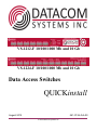
VS-1212-F 10/100/1000 Mb and 10 Gb
VS-1224-F 10/100/1000 Mb and 10 Gb
Data Access Switches
QUICKinstall
August 2012
541-0136-Q-A.00
© 2012 Datacom Systems Inc
2
VS-1212-F and VS-1224-F Data Access Switches
Table of Contents
Section 1 Terms of Use
3
1 Copyright
................................................................................................................................... 3
2 License...................................................................................................................................
Agreement
3
3 Proprietary
...................................................................................................................................
Notice
3
Tradem ark Attribution
.......................................................................................................................................................... 3
4 Certifications
...................................................................................................................................
and Marks
4
5 Safety ...................................................................................................................................
Notices and Warnings
4
Section 2 Overview
5
1 What Shipped?
................................................................................................................................... 6
2 Specifications
................................................................................................................................... 6
3 Supported
...................................................................................................................................
SFP Transceivers
6
4 Front —
...................................................................................................................................
Any-to-Any Ports
7
5 Front —
...................................................................................................................................
Power and Status Indicators
7
6 Front —
...................................................................................................................................
Display and Buttons
8
7 Rear —...................................................................................................................................
Power Module8
8 Rear —...................................................................................................................................
Management Module
9
Section 3 Network IP Address Configuration
Section 4 Stand-Alone Installation
9
11
1 Power...................................................................................................................................
Connection
11
2 Port Connection
................................................................................................................................... 12
Section 5 Management Connection
12
1 Web Browser
................................................................................................................................... 13
2 TELNET
...................................................................................................................................
or SSH
14
Section 6 Customer Service
16
1 Warranty
................................................................................................................................... 16
2 Limits...................................................................................................................................
of Liability
16
© 2012 Datacom Systems Inc
Terms of Use
1
3
Terms of Use
The following terms and conditions relate to the use of this document. Please note that Datacom
Systems Inc. reserves the right, at its entire discretion, to change, modify, add, or remove portions of
these Terms of Use at any time. Please read the Terms of Use carefully as your use of this document
is subject to the Terms of Use stipulated herein.
1.1
Copyright
Copyright ©2012 by Datacom Systems, Inc. All rights reserved. Printed in the United States of
America. No part of this publication may be reproduced, stored in a retrieval system, or transmitted,
in any form or by any means, electronic, mechanical, photocopying, recording, or otherwise, without
the prior written permission of Datacom Systems, Inc. To obtain this permission, write to the
attention of the Datacom Systems legal department at 9 Adler Drive, East Syracuse, New York
13057-1290, or call +1 315-463-9541.
1.2
License Agreement
Notice To All Users: By using Datacom Systems, Inc. products, you agree to the terms set forth.
No licenses, express or implied, are granted with respect to the technology described and Datacom
Systems, Inc. retains all rights with respect to the technology described herein. If applicable, you
may return the product to the place of purchase for a full refund.
1.3
Proprietary Notice
This document contains proprietary information about the VS-1212-F Data Access Switch and VS1224-F Data Access Switch and is not to be disclosed or used except as authorized by written
contract with Datacom Systems, Inc.
1.3.1
Trademark Attribution
Access Your Network , DS3 ACTIVEtap , DS3switch , ETHERNETtap , Empowering
Network Professionals , FDDIswitch , FIBERsplitter , FIBERswitch , FIBERSWITCHsystem , FLOWcontrol , GIGABITswitch , INSERTswitch , INSERTunit , LANswitch ,
MANAgents , MULTINETswitch , NETspan , PROline , RMON SWITCHINGanalyzer
, UNIVERSALswitch , WANswitch are trademarks of Datacom Systems, Inc. 1ST in Switching
Solutions®, DATACOMsystems®, Empowering Network Professionals®, FLOWcontrol®, LAN
clipper®, LINKprotect ®, MANAgents®, MULTIview®, PERMAlink ®, SIGNALdetect ®,
SINGLEstream®, STREAMLITE , VERSAlink ® and VERSAstream® are registered trademarks
of Datacom Systems, Inc. All other registered and unregistered trademarks are the sole property of
their respective owners. All specifications may be changed without notice.
© 2012 Datacom Systems Inc
4
1.4
VS-1212-F and VS-1224-F Data Access Switches
Certifications and Marks
CAUTION: Changes or modifications to this unit not expressly approved by the party responsible for
compliance could void the user’s authority to operate the equipment.
The CE logo indicates that this equipment was tested and found to meet radiated and
conducted emission to the European Community EMC Directive 89/336/EEC
requirements as per EN 61000-6-3:2001, the generic emissions standard for
residential, commercial and light industrial devices, the limits are those for an EN 55022 Class A
product.
This equipment also has been tested and found to meet the immunity levels for residential,
commercial and light industrial devices according to EN 61000-6-1:2001, the interference severity
levels to the standards and requirements of EN 61000-3-2 Harmonic Current, EN 61000-3-3
Voltage Fluctuations and Flicker, EN 61000-4-2 Electrostatic Discharge, EN 610004-3 Radiated
Susceptibility, EN 61000-4-4 Electrical Fast Transient/Burst, EN 61000-4-5 Surge and EN
61000-4-6 Conducted Susceptibility.
This equipment completed the Product Safety Review and meets the Low Voltage Directive 98/68/
EEC requirements to the standards of EN 60950 Safety of Information Technology Equipment.
The RoHS compliant logo indicates that this electronic product does not exceed the limit
requirements of toxic, hazardous substances or elements as set forth in Directive
2002/95/EC of the European Parliament and of the Council of 27 January 2003 on
the restriction of the use of certain hazardous substances in electrical and electronic equipment.
The crossed out wheelie bin logo signifies that the product can be recycled after being
discarded, and should not be casually discarded as set forth in Directive 2002/96/EC of
the European Parliament and of the Council of 27 January 2003 on waste electrical and
electronic equipment (WEEE).
1.5
Safety Notices and Warnings
These explanatory labels are included for user information.
WARNING: Class 1 laser and LED product. A class 1 laser is safe
under all conditions of normal use. Invisible laser radiation may
be emitted from optical port openings when no fiber cable is
connected, common safety precaution suggests avoid exposure to
laser radiation and do not stare into open optical ports.
© 2012 Datacom Systems Inc
Terms of Use
5
IMPORTANT: Rack Mount Instructions are included here to call the attention of installation
technicians to pertinent safety and warning issues prior to the installation of the product as follows:
A. Elevated Operating Ambient — If installed in a closed or multi-unit rack assembly, the operating
ambient temperature of the rack environment may be greater than room ambient. Therefore,
consideration should be given to installing the equipment in an environment compatible with the
maximum ambient temperature (Tma) specified in the Specifications section.
B. Reduced Air Flow — Installation of the equipment in a rack should be such that the amount of air
flow required for safe operation of the equipment is not compromised.
C. Mechanical Loading — Mounting of the equipment in the rack should be such that a hazardous
condition is not achieved due to uneven mechanical loading.
D. Circuit Overloading — Consideration should be given to the connection of the equipment to the
supply circuit and the effect that overloading of the circuits might have on over-current protection
and supply wiring. Appropriate consideration of equipment nameplate ratings should be used
when addressing this concern.
E. Reliable Earthing — Reliable earthing of rack-mounted equipment should be maintained.
Particular attention should be given to supply connections other than direct connections to the
branch circuit (e.g. use of power strips).
2
Overview
This QUICKinstall for the VS-1212-F Data Access Switch and VS-1224-F Data Access Switch
is intended to get you up and running as fast as possible using the features of your Data Access
Switch. Detailed support, documentation and help can found on the Datacom Systems website
http://www.datacomsystems.com.
The VS-1212-F and VS-1224-F increase network visibility and leverages your investment in
network analyzers, probes, and security equipment. The Data Access Switch filtering and load
balancing functionality allows you to "lighten the load" to your network analyzers, probes, and
security equipment by allowing you to filter only the data you want to monitor and distribute it among
the tools evenly. Greater selectivity and visibility accelerates problem resolution, reduces downtime
and increases enterprise productivity.
Like all Datacom Systems Data Access Products, the VS-1212-F Data Access Switch and VS1224-F Data Access Switch are compatible with all vendor hardware and can be controlled by our
browser based software STREAMLITE™ or Command Line Interface (CLI), which will allow you to
control all of your Data Access Products through a single interface regardless of what network
appliances you choose to deploy.
© 2012 Datacom Systems Inc
6
2.1
VS-1212-F and VS-1224-F Data Access Switches
What Shipped?
1 - VS-1212-F or VS-1224-F
2 - AC Line Cords
1 - DRL512-2M-R cables, DB9 M/F straight thru
2.2
Specifications
VS-1212-F Ports:
12 - SFP; SFP+
VS-1224-F Ports:
24 - SFP; SFP+
Management Port (rear):
RJ45 @ 10/100/1000 Mbs Full-Duplex
Serial Port (rear):
DB9 @ 115,200 bps; 8 data bits; Parity none; 1 stop bit; Flow control none
Input Power Requirement:
100-240VAC 50-60Hz, 4.0-2.0 A
Dimensions (H x W x D):
1.72 x 19.00 x 20.50 inch (4.37 x 48.26 x 52.07 cm)
Weight:
18.15 lbs (8.23 kg)
Operating Temperature:
32º to 104° F (0º to 40° C)
Storage Temperature:
-22º to 149° F (-30º to 65° C)
Humidity:
Less than 95° C non-condensing
Warranty:
One (1) year - see
2.3
5.2 Warranty section for details.
Supported SFP Transceivers
Datacom Systems supports the following small form-factor pluggable (SFP) transceivers and
enhanced small form-factor pluggable (SFP+) transceivers:
NOTE: Removing and reinserting an SFP requires resetting the port speed in the Command Line
Interface (CLI) or the Graphical User Interface (GUI) STREAMLITE™ .
© 2012 Datacom Systems Inc
Overview
7
10G fiber transceivers:
Finisar FTLX8571D3BCV SR/MM dual rate 1G/10G transceiver (SFP+)
Finisar FTLX8571D3BCL SR 10G transceiver (SFP+)
Finisar FTLX1471D3BCV LR/SM dual rate 1G/10G transceiver (SFP+)
Finisar FTLX1471D3BCL LR 10G transceiver (SFP+)
1G copper transceivers:
Finisar FCLF-8521-3 copper multi-rate transceiver (SFP)
1G fiber transceivers:
Finisar FTLF8519P2BCL 1G 850nm MM fiber transceiver (SFP)
Finisar FTLF8519P2BNL 1G 850nm MM fiber transceiver (SFP)
Finisar FTL1318P2BTL 1310nm SM fiber transceiver (SFP)
Finisar FTL1318P3BTL 1310nm SM fiber transceiver (SFP)
Stratos SPLC-20-F-1-D 1G 850nm MM fiber transceiver (SFP)
Stratos SPLC-20-42M-BH-R6 1G 1310nm SM fiber transceiver (SFP)
2.4
Front — Any-to-Any Ports
The Any-to-Any PORTS are SFP+ sockets used for connection to devices and network segments.
The LINK STATUS KEY is the LED status guide for each SFP socket.
VS-1212-F
VS-1224-F
2.5
Front — Power and Status Indicators
VS-1212-F
VS-1224-F
The POWER 1, POWER 2 LEDs illuminate green when the unit power is switched ON with power
available to both of the two rear AC power sockets. Although only one power source is required to
© 2012 Datacom Systems Inc
8
VS-1212-F and VS-1224-F Data Access Switches
power the VS-1212-F and VS-1224-F, use of a second independent power source is strongly
recommended to assure uninterrupted monitoring.
To power the unit ON: Power ON by depressing the AC power switch bar icon located on the rear
panel. The powered ON VS-1212-F and VS-1224-F is indicated by the illuminated green POWER
1 and POWER 2 LEDs on the front panel when the rear panel AC power switch is depressed ON
and AC power is available at both the two rear AC power sockets. Either POWER 1, POWER 2
LED illuminated red indicates a defective power source and immediate investigation as to the cause
is required to insure redundant power integrity.
The STATUS LED indicator is orange during the boot-up cycle and turns green upon a successful
boot sequence indicating the Data Access Switch is operational.
NOTE: STATUS LED indicator indicates the device is ready several seconds before it is ready to
respond to Command Line Interface (CLI) commands.
2.6
Front — Display and Buttons
The display shows Port status. The Selectable Buttons are for future use.
VS-1212-F
2.7
Rear — Power Module-
Two AC input power sockets are provided on the rear panel. The front panel POWER 1, POWER 2
LEDs are illuminated green, respectively, when the AC power switch is depressed ON and AC
power is available at both the two rear AC power sockets. Either POWER 1, POWER 2 LED
illuminated red indicates a defective power source and immediate investigation as to the cause is
required to insure redundant power integrity.
Although only one power supply is required to power the VS-1212-F and VS-1224-F, use of a
second independent power source is strongly recommended to assure uninterrupted monitoring.
© 2012 Datacom Systems Inc
Overview
9
Furthermore, connecting the second AC input power socket to a different external power source
circuit than the first AC input power source eliminates power as a single point of failure.
The AC power switch is a rocker style switch. The circle icon
depressed is OFF and the bar icon depressed is ON. To
power the unit ON, depress switch bar icon. The powered ON
VS-1212-F and VS-1224-F is indicated by the illuminated
green POWER 1 and POWER 2 LEDs on the front panel.
2.8
Rear — Management Module
The SERIAL 1 connector port is a shielded DB9 Female and is
cabled to the COM port of any compatible network tool or PC
with any terminal emulation application resides using the
Datacom Systems Command Line Interface (CLI) Software.
The SERIAL 2 connector port is reserved for future use
The MANAGEMENT connector port is a shielded RJ45 and is cabled to the network.
Media Access Control (MAC) address identifier and certification compliance identifiers are
provided on this rear label.
3
Network IP Address Configuration
All VS-1212-F and VS-1224-F series units are shipped with a factory default configuration as
follows:
IP Address:192.168.1.1; Subnet Mask: 255.255.0.0; Gateway: 192.168.1.0
User name: Administrator password: admin
IMPORTANT: If you expect to remotely connect to the VS-1212-F and VS-1224-F series, you
must change the IP Address, Subnet Mask and Gateway to match your Local Area Network.
Note: If your VS-1212-F and VS-1224-F already has the IP Address, Subnet Mask and Gateway
set for your network, you may proceed to the 'Stand-Alone Installation 11 ' section.
This simplified sample initial configuration uses the SERIAL1 DB9 Female port.with the shipped
DRL512-2M-R DB9 M/F straight thru cable. Any freely available terminal emulator (PuTTy or
Tera Term for example) may be used, but please note the following specific terminal settings:
115,200 bits per second; 8 data bits; Parity none; 1 stop bit; Flow control none
Step 1. Connect your PC and your VS-1212-F or VS-1224-F using the provided Datacom
Systems DRL512-2M-R cable. Connect the DB9 Female pin end to the serial port on your PC and
connect the DB9 Male pin to the CONTROL port on your VS-1212-F or VS-1224-F.
© 2012 Datacom Systems Inc
10
VS-1212-F and VS-1224-F Data Access Switches
NOTE: For PCs without 9-pin serial ports, check with you product representative for available
sources of a USB to RS-232 Plug-in Adapter.
Step 2. Using a supplied AC Line Cord, plug the VS-1212-F Data Access Switch or VS-1224-F
Data Access Switch into the external power source. Note that either POWER 1 or POWER 2 LED
is illuminated green indicating power is available at the rear AC power socket to which the AC Line
Cord is connected. The other POWER LED is illuminated red indicating a lack of power to the
unconnected AC power socket. Depress the AC power switch bar icon to power ON the VS1212-F or VS-1224-F which is indicated by the internal cooling fans powering up.
Step 3. Open the terminal emulation application on your PC and configure the SERIAL COM
Properties: 115,200 bits per second; 8 data bits; parity none; 1 stop bit and flow control none.
Step 4. Hitting the Enter key twice in a row (i.e., Enter, Enter) establishes a connection, displays
the Command shell prompt, then type ? and press Enter to see a list of available commands.
Step 5. Set the IP address by typing SET IP xxx.xxx.xxx.xxx where xxx.xxx.xxx.xxx corresponds
to a valid IP address for your network. Press the Enter key to continue.
Step 6. Set the default gateway (if needed) by typing SET GATEWAY xxx.xxx.xxx.xxx where xxx.
xxx.xxx.xxx corresponds to your network's default gateway. Press the Enter key to continue.
Step 7. Set the subnet mask by typing SET SUBNET xxx.xxx.xxx.xxx where xxx.xxx.xxx.xxx
corresponds to your network's subnet mask. Press the Enter key to continue.
Step 8. Type EXIT to save the network address changes and press the Enter key to end the
connection session indicated by 'Connection closed' response.
Step 9. Hit the Enter key twice in succession (i.e., Enter, Enter) to establish another connection
session with the VS-1212-F or VS-1224-F, type SHOW and press the Enter key to review the
network address settings. Verify that the settings are correct.
Step 10. Type EXIT and press the Enter key to end the connection session indicated by
'Connection closed' response. Then close the HyperTerminal window responding 'Yes' to the "You
are currently connect. Are you sure you want to disconnect now?' prompt.
© 2012 Datacom Systems Inc
Network IP Address Configuration
11
Step 11. Disconnect the DRL512-2M-R serial cable from your VS-1212-F Data Access Switch or
VS-1224-F Data Access Switch and proceed to install the VS-1212-F or VS-1224-F in your
chosen network location.
4
Stand-Alone Installation
This section will focus on a simple configuration which describes the typical VS-1212-F Data
Access Switch and VS-1224-F Data Access Switch hardware installation at the network location of
your choice.
4.1
Power Connection
Two AC input power sockets are provided on the rear panel. The front panel POWER 1, POWER 2
LEDs are illuminated green, respectively, when the AC power switch is depressed ON and AC
power is available at both the two rear AC power sockets. Either POWER 1, POWER 2 LED
illuminated red indicates a defective power source and immediate investigation as to the cause is
required to insure redundant power integrity.
Step 1. Using the supplied AC Line Cords, plug the VS-1212-F Data Access Switch and VS1224-F Data Access Switch into different circuit external power sources.Although only one power
supply is required to power the VS-1212-F and VS-1224-F, use of a second independent power
source is strongly recommended to assure uninterrupted monitoring. Furthermore, connecting the
second AC power socket to a different external power source circuit than the first AC power
source eliminates power as a single point of failure.
The AC POWER switch is a rocker style switch. The AC power switch circle icon depressed is OFF
. The AC power switch bar icon depressed is ON.
Step 2. Power ON the VS-1212-F and VS-1224-F by depressing the AC power switch bar icon.
The powered ON VS-1212-F and VS-1224-F is indicated by the illuminated green POWER 1 and
POWER 2 LEDs on the front panel.
© 2012 Datacom Systems Inc
12
4.2
VS-1212-F and VS-1224-F Data Access Switches
Port Connection
This section will focus on the PORT connection of the typical VS-1212-F Data Access Switch
hardware installation. The VS-1224-F Data Access Switch hardware installation is similar to the
typical VS-1212-F Data Access Switch hardware installation.
Step 1. Connect the network cables to PORT sockets as has been determined in your data access
switch network layout. The LED display above each port will indicate LINK as defined in the LINK
STATUS KEY box.
Step 2. Continue repeating Step 1. for any remaining PORT you want to connect from the VS1212-F Data Access Switch or VS-1224-F Data Access Switch.
5
Management Connection
Once installation of the VS-1212-F Data Access Switch and VS-1224-F Data Access Switch has
been completed in your chosen network location.
This section will focus on the MANAGEMENT PORT 10/100/1000 Mbs Full-Duplex connection of
the typical VS-1212-F Data Access Switch and VS-1224-F Data Access Switch hardware
installation.
Connect a network cable to the MANAGEMENT port RJ45 socket. The MANAGEMENT port RJ45
left LED illuminates green when link has been established with the network. The MANAGEMENT
port right LED illuminates green when passing data. Management connection may be initiated over
the network via Web Browser, Telnet or SSH as explained in the following sections.
© 2012 Datacom Systems Inc
Management Connection
5.1
13
Web Browser
This section describes the intuitive Web Browser Graphical User Interface (GUI) Login session.
Web Browsers supported are Microsoft Internet Explorer 8.0 and Mozilla Firefox 9.0.1. Only
encrypted (HTTPS) web sessions are supported, unencrypted (HTTP) web sessions are NOT
supported.
Step 1. Users access the GUI through the Web Browser with the following address: https://
<ip_address> . Use the IP address set in the previous "SERIAL Port (DB9) Network IP Address
Configuration 9 ' section. In this example https;//10.1.53.86.
Step 2. Users will be prompted with the login screen. Users can login with the Username '
Administrator' and default password 'admin'.
The Home window is the first screen upon successful User login.
With an active browser connection, Logout will automatically occur after 5 minutes of inactivity
[default setting of 5 minutes can be change under Setup > System > Interface Timeouts.]
© 2012 Datacom Systems Inc
14
VS-1212-F and VS-1224-F Data Access Switches
Step 3. If additional user operational GUI navigational help or information is necessary, detailed
support, documentation and help can found on the Datacom Systems website http://www.
datacomsystems.com.
Step 4. In the upper right window Click 'Logout' to end the session>
Step 5. Close the Web Browser.
5.2
TELNET or SSH
Most network equipment and operating systems with a TCP/IP stack also support some kind of
TELNET service server for remote connection. Security-related shortcomings have limited TELNET
(TErminaL NETwork) usage, although TELNET is still widely used when diagnosing problems,
manually "talking" to other services without specialized client software, and administration of network
elements such as integration and maintenance of core network elements.
Secure Shell (SSH ) is a network protocol that uses public key cryptography that allows secure
network services to be exchanged over an insecure network between two networked devices. SSH
Secure Shell with its array of unmatched security features is an essential tool in today's network
environment. It is a powerful guardian against the numerous security hazards that nowadays threaten
network communications.
© 2012 Datacom Systems Inc
Management Connection
15
IMPORTANT: For Host Name (or IP address), if initial IP Address HAS BEEN configured, as shown
below, use the Local Area Network address setting input during initial 'SERIAL Port (DB9)
Network IP Address Configuration 9 '. Otherwise, if initial IP Address HAS NOT BEEN configured, a
direct-connect cross-over cable to PC and custom configured computer IP and Subnet must be set
in order to use the factory default IP Address:192.168.1.1, Subnet Mask 255.255.0.0, Gateway:
192.168.1.0, User name: Administrator, Password: admin
Step 1. Open any freely available terminal emulator (PuTTy or Tera Term for example) on your PC,
select Telnet or SSH type connection, enter the Host Name or IP address and open the connection..
If you are using SSH to connect for the first time, a message something like this will display:
This SSH feature is designed to protect against a network attack known as spoofing: redirecting
your connection to a different computer, so that you send your password to the wrong machine. To
prevent this attack, each SSH Server has a unique identifying code, called a host key. So if you
connect to a SSH Server and it sends you a different host key from the one you were expecting, you
will have the chance to abandon your connection before you type any private information (such as a
password) into it. So the warning message above asks you whether you want to trust this host key
or not.
Whether or not to trust the host key is your choice. If you are connecting within a company network,
you might feel that all the network users are on the same side and spoofing attacks are unlikely, so
you might choose to trust the key without checking it. If you are connecting across a hostile network
(such as the Internet) you should check with your system administrator, perhaps by telephone or in
person.
Step 3. After you have connected, you will be asked to login:, type the username: Administrator
(default value) and press the Enter key. At the Password: prompt, type admin (default value) and
press the Enter key to display the command line > prompt. To see a list of available commands, at
the > command line prompt, type ? and press the Enter key.
Step 4. If additional user operational CLI navigational help or information is necessary, detailed
support, documentation and help can found on the Datacom Systems website http://www.
datacomsystems.com.
Step 5. Type Exit and press the Enter key to end the connection session.
© 2012 Datacom Systems Inc
16
6
VS-1212-F and VS-1224-F Data Access Switches
Customer Service
Datacom Customer Service is available via telephone and Internet. Please leave a voice message
and our Customer Service Staff will return your call as soon as possible. You may also find the
assistance you need at our website: http://www.datacomsystems.com.
Telephone:
+1 315 463-9541
Internet website: http://www.datacomsystems.com
6.1
Warranty
See http://www.datacomsystems.com for warranty detailed information.
6.2
Limits of Liability
See http://www.datacomsystems.com for Limits of Liability detailed information.
© 2012 Datacom Systems Inc
Datacom Systems Inc.
9 Adler Drive • East Syracuse, NY 13057
TEL: +1 315 463-9541 • FAX: +1 315 463-9557
http://www.datacomsystems.com