1
Filtered SINGLEstream™
Link Aggregation Tap
User’s Guide
FSS-1000 Series (BT, SX, LX)
FSS-2000 Series (BT, SX, LX, BT/SX, BT/LX)
July 2006
541-0105-U-A.00
© 2006 by Datacom Systems Inc. All rights reserved.
License Agreement
Notice to All Users: By using a Datacom Systems, Inc. Filtered SINGLEstream™ Link Aggregation Tap you
agree to the terms set forth. No licenses, express or implied, are granted with respect to the technology
desribed and Datacom Systems, Inc. retains all rights with respect to the technology described herein. If
applicable, you may return the product to the place of purchase for a full refund.
Trademark Attribution
DS3 ACTIVEtap™, DS3switch™, Empowering Network Professionals™, ETHERNETtap™, FDDIswitch™,
FIBERsplitter™, FIBERswitch™, FIBERSWITCHsystem™, GIGABITswitch™, INSERTswitch™, INSERTunit™,
LANswitch™, MULTINETswitch™, NETspan™, PERMAlink™, PROline™, RMON SWITCHINGanalyzer™,
SINGLEstream™, UNIVERSALswitch™, VERSAstream™, and WANswitch™ are trademarks of Datacom Systems,
Inc. 1st in Switch Solutions®, DATACOMsystems®, LANclipper®, MANAgents® and MULTIview® are registered
trademarks of Datacom Systems, Inc. All other registered and unregistered trademarks are the sole property
of their respective owners. All specifications maybe changed without notice.
Proprietary Notice
This document contains proprietary information about the Filtered SINGLEstream™ Link Aggregation Tap
and is not to be disclosed or used except as authorized by written contract with Datacom Systems, Inc.
Table of Contents
1 Introduction
1
1.1 What is included
1
1.2 Descriptions of the Filtered SINGLEstream™ Models
2
1.3 Typical Application Diagram
6
1.4 Conventions used in the User’s Guide
7
1.5 Installation
8
1.5.1 Fiber Monitor Ports
8
1.5.2 Rack Mounting the Filtered SINGLEstream™
8
2 Connecting Network Taps
10
2.1 Connecting a 10/100/1000BaseT Network Tap
10
2.2 Connecting a Fiber Network Tap
13
2.3 Connecting Multiple Tap Connections Using a Single Network Tap 17
2.4 Verify Proper Network Connections
17
3 Installing the FLOWcontrol™ Software
18
4 Configuring the IP Address of a Filtered SINGLEstream™
21
4.1 Configuring the IP Address – HyperTerminal
21
4.2 Configuring the IP Address – FLOWcontrol™, Serial Connection
29
4.3 Configuring the IP Address – FLOWcontrol™, LAN Connection
32
5 Using the Filter Product Console Software
37
5.1 Creating a Connection Agent
37
5.2 Pull-down Menus
41
5.2.1 File Pull-down Menu
41
5.2.2 Agent Pull-down Menu
41
5.2.3 Filter Pull-down Menu
42
5.2.4 Control Pull-down Menu
42
5.2.5 Utilities Pull-down Menu
43
5.2.6 Help Pull-down Menu 45
5.3 Configuration Tabs
46
5.3.1 Operational Tab
46
5.3.2 Port Configuration Tab
47
5.3.3 Filter Configuration Tab
48
5.3.4 Aggregation Configuration Tab
58
5.3.5 Event Log Tab
59
5.4 Example Use of Filter Product Console - Printer Traffic
Appendix A Description of Frames and Packets
60
65
A.1 Ethernet Frame Formats
66
A.2 IP Packet Format
67
Appendix B HyperTerminal Commands
68
Appendix C Product Specification 70
Index
71
Customer Service
74
Compliance Testing
74
Factory Warranty
75
Limitations on Liability
75
Force Majeure
75
Copyright
75
ii
List of Figures
Figure 1.1 Front Panel of the FSS-2000BT/SX
4
Figure 1.2 FSS Network Tap and Monitor Port Numbering
5
Figure 1.3 Back View of the FSS
5
Figure 1.4 FSS-2000BT Application
6
Figure 1.5 FSS Mounting Hardware
8
Figure 2.1 10/100/1000BaseT Network
10
Figure 2.2 FSS-2000BT with 10/100/1000BT Network Tap 1A
10
Figure 2.3 FSS-2000BT with 10/100/1000BT Network Tap 1A and 1B
11
Figure 2.4 10/100/1000BaseT Network Tap Link LED
11
Figure 2.5 FSS-2000BT with Two 10/100/1000BT Network Taps
11
Figure 2.6 10/100/1000BaseT Network Tap using FSS-2000BT
12
Figure 2.7 Fiber Network
13
Figure 2.8 FSS-1000LX with Network Tap 1A
14
Figure 2.9 FSS-1000LX with Network Tap 1A and 1B
14
Figure 2.10 Fiber Network Tap Link LED
15
Figure 2.11 FSS-2000LX with Two Fiber Network Taps
15
Figure 2.12 Fiber Network Tap using FSS-1000LX
16
Figure 2.13 FSS-2000BT/LX Application
17
Figure 3.1 FLOWcontrol™ Security Warning
18
Figure 3.2 FLOWcontrol™ Installation Status
18
Figure 3.3 FLOWcontrol™ Startup Icon
19
Figure 3.4 FLOWcontrol™ Main Screen
19
Figure 4.1 FSS Serial Connection using HyperTerminal
21
Figure 4.2 HyperTerminal Connection Description Window
22
Figure 4.3 HyperTerminal Connect To Window
23
Figure 4.4 HyperTerminal COM Properties Window
24
Figure 4.5 FSS HyperTerminal Login Window
25
Figure 4.6 FSS Commands Window
26
Figure 4.7 FSS IP Configuration Window
27
Figure 4.8 FSS Show Window
iii
28
Figure 4.9 FSS Serial Connection
29
Figure 4.10 FLOWcontrol™ Local Connectivity
29
Figure 4.11 FLOWcontrol™ Login Window
30
Figure 4.12 FLOWcontrol™ Main Window Connected to an FSS-2000BT/SX
30
Figure 4.13 Product Options Window
31
Figure 4.14 FSS Management Port Connection
32
Figure 4.15 FLOWcontrol™ Main Window
33
Figure 4.16 FLOWcontrol™ Product Configuration Window
34
Figure 4.17 FLOWcontrol™ Login Window
35
Figure 4.18 Main FLOWcontrol™ Window Connected to an FSS-2000BT/SX
35
Figure 4.19 Product Options Window
36
Figure 5.1 FLOWcontrol™ Main Window
37
Figure 5.2 FLOWcontrol™ Product Configuration Window
38
Figure 5.3 FLOWcontrol™ Agent → Connect
39
Figure 5.4 FLOWcontrol™ Login Window
39
Figure 5.5 FLOWcontrol™ Main Window Connected to an FSS-2000BT/SX
40
Figure 5.6 File Pull-down Menu
41
Figure 5.7 Agent Pull-down Menu
41
Figure 5.8 Filter Pull-down Menu
42
Figure 5.9 Control Pull-down Menu
42
Figure 5.10 Utilities → Upgrade Pull-down Menu
43
Figure 5.11 Utilities → Options Menu
44
Figure 5.12 Utilities → User Accounts Pull-down Menu
45
Figure 5.13 Help Pull-down Menu
45
Figure 5.14 Operational Tab
46
Figure 5.15 Port Configuration Tab
47
Figure 5.16 Filter Configuration Tab → Saved Filters 48
Figure 5.17 Filter Configuration Tab → Basic
49
Figure 5.18 Filter Configuration Tab → Basic → MAC Address Filtering
50
Figure 5.19 Filter Configuration Tab → Basic → VLAN Filtering
51
iv
Figure 5.20 Filter Configuration Tab → Basic → Frame Type Filtering
52
Figure 5.21 Filter Configuration Tab → Basic → Protocol Filtering
53
Figure 5.22 Filter Configuration Tab → Basic → IP Address Filtering
54
Figure 5.23 Filter Configuration Tab → Basic → Port Filtering
55
Figure 5.24 Creating a Rule Using the Filter Configuration Tab → MAC Address Filtering
56
Figure 5.25 Filter Functions Window
57
Figure 5.26 Aggregation Configuration Tab
58
Figure 5.27 Event Log Tab
59
Figure 5.28 FSS-2000BT Network Printer Application
60
Figure 5.29 FSS-2000BT Network Printer Application with Network Analyzer
61
Figure 5.30 Port Configuration Tab - Network Printer Application
62
Figure 5.31 Aggregation Configuration Tab - Network Printer Application
63
Figure 5.32 Filter Configuration Tab - Network Printer Application
64
Figure A.1 Ethernet Frame Encapsulation of an IP Packet
65
Figure B.1 FSS Serial PC Connection
68
Figure B.2 HyperTerminal COM Properties Window
68
List of Tables
Table 1.1 FSS-1000 Model Configurations
2
Table 1.2 FSS-2000 Model Configurations
3
Table A.1 Bit Mapping of an Ethernet Frame
66
Table A.2 Bit Mapping of an IP Packet
67
Table B.1 FSS HyperTerminal Commands
69
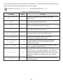
Table C.1 Filtered SINGLEstream™ Product Specifications
70
vi
1 Introduction
Congratulations on the purchase of your new Filtered SINGLEstream™. The Filtered SINGLEstream™ from
Datacom Systems, the premiere provider of network access solutions, provides you with unprecedented
flexibility for your network monitoring needs. The Filtered SINGLEstream™ adds powerful filtering
capabilities to the link aggregation, port regeneration, and port assignment capabilities of other
products from Datacom Systems. This User’s Guide will help you install, configure, and use your Filtered
SINGLEstream™ effectively and efficiently. For information regarding the initial installation of your Filtered
SINGLEstream™, please refer to the included Quick-Connect Guide.
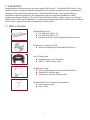
1.1 What is included
Filtered SINGLEstream™
■ FSS-1000 Series (BT, SX, LX)
■ FSS-2000 Series (BT, SX, LX)
■ Optional Small Form-Factor Pluggable Fiber Transceivers
FLOWcontrol™ software CD-ROM
■ Allows for configuration of Filtered SINGLEstream™
Two AC Power Cords
■ Standard country-style wall outlet
■ 100VAC - 240VAC power source
Configuration Cables
■ Serial to USB configuration cable (Cable #DRL434-6)
■ Standard 3 ft. Ethernet cable
■ Standard 3 ft. crossover Ethernet cable
Filtered SINGLEstream™ Product Documentation
■ Quick Connect Guide
■ User’s Guide
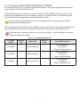
1.2 Descriptions of the Filtered SINGLEstream™ Models
The Filtered SINGLEstream™ is available in eight different models. This section provides details about the
various models of the Filtered SINGLEstream™.
All Filtered SINGLEstream™ models come standard with four 10/100/1000BaseT Monitoring Ports. Small
Form-Factor Pluggable fiber inserts are available separately to activate up to four Fiber Monitoring Ports.
Each Small Form-Factor Pluggable may be Single or Multimode fiber.
Small Form-Factor Pluggable fiber inserts are an available option to activate up to four Single or
Multimode Fiber Monitoring Ports
!
The FSS-1000 series Filtered SINGLEstream™ models provide a single Network Tap and four Monitoring Ports.
The models differ from each other based on the network media required to create the Network Tap.
TIP
Multimode fiber is commonly referred to as short haul or SX fiber. Single-mode fiber is commonly
referred to long haul or LX fiber.
Table 1.1 FSS-1000 Model Configurations
FSS-1000
Model
Network
Taps
Type of Tap
Monitor
Ports
Type of Monitor Ports
FSS-1000BT
1
10/100/1000BaseT
4
10/100/1000BaseT
Or Optional
Single- / Multimode Fiber
4
10/100/1000BaseT
Or Optional
Single- / Multimode Fiber
4
10/100/1000BaseT
Or Optional
Single- / Multimode Fiber
FSS-1000SX
FSS-1000LX
1
1
Multimode Fiber
Single-mode Fiber
The FSS-2000 series Filtered SINGLEstream™ models provide two Network Taps and four Monitoring Ports.
The models differ from each other based on the network media required to create each Network Tap. BT/SX
and BT/LX models allow for up to four sets of Network Tap connections to be made, but only two Network
Taps are operational at one time.
All Filtered SINGLEstream™ models come standard with four 10/100/1000BaseT Monitoring Ports. Small
Form-Factor Pluggable fiber inserts are available separately to activate up to four Fiber Monitoring Ports.
Each Small Form-Factor Pluggable may be Single or Multimode fiber.
!
Small Form-Factor Pluggable fiber inserts are an available option to activate up to four Single or
Multimode Fiber Monitoring Ports
Table 1.2 FSS-2000 Model Configurations
FSS-2000
Model
Network
Taps
Type of Tap
Monitor
Ports
Type of Monitor Ports
FSS-2000BT
2
(2) 10/100/1000BaseT
4
10/100/1000BaseT
Or Optional
Single- / Multimode Fiber
FSS-2000SX
2
(2) Multimode Fiber
4
FSS-2000LX
2
(2) Single-mode Fiber
4
2
(2) 10/100/1000BaseT
(2) Multimode Fiber
2
(2) 10/100/1000BaseT
(2) Single-mode Fiber
FSS-2000BT/SX
FSS-2000BT/LX
10/100/1000BaseT
Or Optional
Single- / Multimode Fiber
10/100/1000BaseT
Or Optional
Single- / Multimode Fiber
4
10/100/1000BaseT
Or Optional
Single- / Multimode Fiber
4
10/100/1000BaseT
Or Optional
Single- / Multimode Fiber
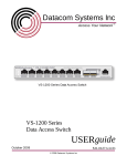
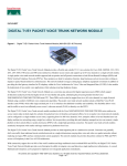
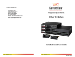
The figure below shows the front of an FSS-2000BT/SX model. Some models do not have all of the ports that
are shown below. Each Filtered SINGLEstream™ model is physically similar, however. All models have similar
power connections on the back panel, Power LEDs, Network Tap connections, Monitor Port connections,
and management connections.
Monitor Port
Monitor Link LED - A solid light indicates the Fiber or
10/100/1000BaseT network segment is connected. A
blinking light indicates the presense of network traffic.
Tx Rx
Fiber Monitor Port - Optional Small Form Factor
Pluggable Tranceivers activate up to four Fiber
Monitoring Ports.
10/100/1000BaseT Monitor Port - Available on all
models.
On Back
Management Port - 10/100BaseT port
for local or remote management.
Power Connector - Dual
100 VAC - 240VAC
connectors
Serial Port - For local
management.
Power LED - A solid light
indicates connection to
each power supply.
Network Tap
Tap Link LED - A solid light indicates the Fiber or
10/100/1000BaseT network segment is connected. A
blinking light indicates the presence of network traffic.
Tx Rx
Tx Rx
Fiber Network Tap - Fiber
Tap available on FSS LX and
SX models.
10/100/1000BaseT Network Tap - Ethernet
TAP available on FSS BT models.
Figure 1.1 Front Panel of the FSS-2000BT/SX
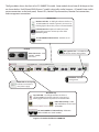
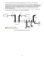
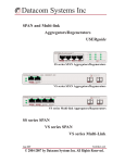
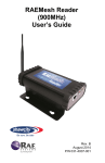
The figure below indicates how the various ports are numbered. Network Tap ports are on the left, Monitor
ports are on the right. Network Taps always consist of ports A and B – regardless if the connection is fiber
or 10/100/1000BaseT. Network Tap connections are dependent upon the Filtered SINGLEstream™ model.
All Filtered SINGLEstream™ models have four Monitor Ports. Monitor Ports always have 10/100/1000BaseT
connections. Small Form Factor Pluggable fiber inserts are an available option to activate up to four Single
or Multimode Fiber Monitoring Ports. Only one type of port can be used at a time when both are available.
Management Port - 10/100BaseT port
for local or remote management.
1A
1B
2A
2B
1
Network Taps
2
3
4
Monitor Ports
Serial Port - For local management.
Figure 1.2 FSS Network Tap and Monitor Port Numbering
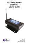
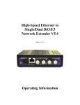
The figure below shows the back of the Filtered SINGLEstream™. The connections for the power cables are
on the back. Only one power source is required, but the Filtered SINGLEstream™ provides for two power
connections. To create true redundancy, the power cords should be connected to separate power circuits.
In the event that power is lost, the Filtered SINGLEstream™ passively allows network traffic to flow across the
tapped network (assuming that the external network equipment is still powered).
Figure 1.3 Back View of the FSS
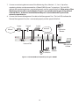
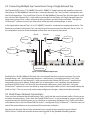
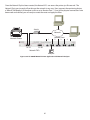
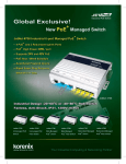
1.3 Typical Application Diagram
The figure below shows an FSS-2000BT Filtered SINGLEstream™ in a network. In this example, two
10/100/1000BaseT Network Taps are created. Network Tap 1 is created between the Router and the Firewall.
Network Tap 2 is created between the Firewall and the Internal Network Switch. Four monitoring devices are
also connected, three via 10/100/1000BaseT connections and one via a Fiber connection.
Tx
Switch
Firewall
Router
Rx
Application
Monitor
Network
Internet
Monitor Ports
2
3
1
1A 1B
4
Tx Rx
2A 2B
Remote
Management
Console
Network TAPs
IDS
Forensic Analyzer
Collection
Figure 1.4 FSS-2000BT Application
All the network traffic that would normally pass between the Router and the Firewall is still passed as
normal. Both Network Taps on the Filtered SINGLEstream™ act as passive network taps. Any information
that passes through the tap is duplicated, buffered, and then available to be filtered and routed to any of
the connected monitoring devices. The powerful flexibility of Filtered SINGLEstream™ allows the user to
quickly monitor very specific network traffic from remote locations without ever having to disconnect and
reconnect the cables leading to various monitoring devices.
The following sections of this User’s Guide provide details about how to create a Network Tap, install
the FLOWcontrol™ software, and use the FLOWcontrol™ software to tailor your Filtered SINGLEstream™
configuration to meet your network monitoring needs. Each of the following sections of the User’s Guide
has its own list of Quick Tips – putting the information you need right where you need it.
1.4 Conventions used in the User’s Guide
To avoid confusion, the following conventions are used throughout this User’s Guide:
■ When characters are to be typed on a PC, they are written in Courier New Font
- On the command line, type SET IP ADDRESS 192.168.1.1
■ When a specific keyboard key is to be pressed, it will be enclosed in < > and written in italics
- Then press <Enter> , or
- Then press <Ctrl + Shift> (press both keys together)
■ Buttons and tabs are indicated in Bold Text
- Select the Filter Configuration tab, and then click OK.
■ Selections on pull-down menus will be indicated by the use of arrows (→)
- Select Main → Lower Level Selection → Lowest Level Selection
TIP
■
is used to indicate a related feature, a quick method, or another approach to accomplish the
current activity
■
TIP
!
-
instead of clicking OK, you may also press <Enter>.
is used to indicate a special notice
!
Ensure that the Tx and Rx connections are made properly.
1.5 Installation
1.5.1 Fiber Monitor Ports
All Filtered SINGLEstream™ models come standard with four 10/100/1000BaseT Monitoring Ports. Small
Form-Factor Pluggable fiber inserts are available separately to activate up to four Fiber Monitoring Ports.
Each Small Form-Factor Pluggable may be Single or Multimode fiber. Simply insert each Small Form-Factor
Pluggable Transceiver into the appropriate Fiber Monitor Port.
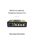
1.5.2 Rack Mounting the Filtered SINGLEstream™
Each Filtered SINGLEstream™ is equipped with brackets that allow it to be mounted in a standard 19-inch
rack. To secure your Filtered SINGLEstream™ in a standard rack, simply secure four screws that fit your rack
through the gaps in the Filtered SINGLEstream’s ™ mounting brackets. One of the mounting brackets is
shown in the figure below.
TIP
To assist mounting the Filtered SINGLEstream™, start the lower screws first.
Secure Screws
Figure 1.5 FSS Mounting Hardware
The dimensions and weight for all FSS models are given below
■ Sizes: 3” (7cm) H x 18” (40cm) W x 9” (20cm) D
■ Unit Weight: 7 lbs (3.2 kg)
!
Be sure to leave enough room for all the cable connections (front and back). Also, be sure to leave
enough space between rack-mounted equipment to allow for proper airflow and ventilation
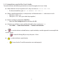
Quick Tips: Creating a Network Tap
■ FSS-1000 series models allow for a single Network Tap to be connected
■ FSS-2000 series models allow for two Network Taps to be connected
■ Multimode fiber is commonly referred to as short haul or SX fiber.
■ Single-mode is fiber is commonly referred to long haul or LX fiber.
■ LX models allow for Single-mode Fiber connections
■ SX models allow for Multimode Fiber connections
■ By default, the Filtered SINGLEstream™ connection speed is set to 1 Mbps, full duplex. It is highly
recommended you configure the Filtered SINGLEstream™ to use a specific speed if desired.
■ You may connect four different Network Taps, however, only 2 can be active at any one time. If both
10/100/1000BaseT and Fiber connections are made for a single Network Tap, the user can dictate which
tap is used by default via the FLOWcontrol™ software.
2 Connecting Network Taps
To monitor traffic on your network, you must first connect a Network Tap at the desired monitoring point.
2.1 Connecting a 10/100/1000BaseT Network Tap
If you have a Filtered SINGLEstream™ model FSS-1000BT, FSS-2000BT, FSS-2000BT/SX, or FSS-2000BT/LX, use
the following procedure to connect a 10/100/1000BaseT Network Tap.
The Filtered SINGLEstream™ is configured by default with a connection speed is set to 10000 megabits per
second, full duplex. Once you have connected a Network Tap, you must use the FLOWcontrol™ software to
specifically set the connection speed of the Filtered SINGLEstream™. All 10/100/1000BaseT Network Taps
will be physically similar, regardless of speed.
1. Identify the point within the network where you would like to connect a Network Tap.
The monitored point can be any point that is of particular interest to you. For example, you may
wish to monitor the data exchanged between the public Internet and your local intranet. You will
be able to connect an appropriate Network Tap to monitor any network traffic of interest.
TIP
2. Verify that the Filtered SINGLEstream™ is powered on by checking the Power LEDs on the front of the
Filtered SINGLEstream™.
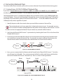
3. Disconnect the network cable that connects the two external networking devices between which
you would like to connect the Network Tap. For example, to connect a Network Tap between the
Internet Router and the Firewall remove the cable between the Firewall and the Router.
Router
Switch
Firewall
Network
Internet
1A 1B
Figure 2.1 10/100/1000BaseT Network
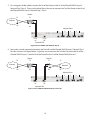
4. Next, you must connect both the Router and the Firewall to the Filtered SINGLEstream™. To do this,
you will need two LAN cables. First, connect one end of the first cable to the Router, and the other
end to the Filtered SINGLEstream™ Network Tap 1 Port A as shown in the figure below.
Switch
Firewall
Router
Network
Internet
1
1A 1B
Monitor Ports
2
3
2A 2B
Network TAPs
Figure 2.2 FSS-2000BT with 10/100/1000BT Network Tap 1A
10
4
5. Then connect one end of the second LAN cable to the Firewall and the other end to the Filtered
SINGLEstream™ Network Tap 1 Port B as shown in the figure below.
Switch
Firewall
Router
Network
Internet
1
1A 1B
Monitor Ports
2
3
4
2A 2B
Network TAPs
Figure 2.3 FSS-2000BT with 10/100/1000BT Network Tap 1A and 1B
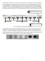
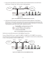
6. Verify that the LEDs indicate that a network connection has been established. On the Filtered
SINGLEstream™, the Link LEDs are located on the front panel, immediately next to the Network Tap
port connections. A solid light indicates that a connection has been established at the stated speed.
A blinking light indicates that network traffic is detected on the link.
10
100
1000
Tap Link LED - A solid light indicates the Fiber
or 10/100/1000BaseT network segment is
connected. A blinking light indicates the
presence of network traffic.
Figure 2.4 10/100/1000BaseT Network Tap Link LED
You have now successfully connected a 10/100/1000BaseT Network Tap
Owners of Filtered SINGLEstream™ models FSS-2000BT, FSS-2000BT/SX, or FSS-2000BT/LX can connect a
second Network Tap at another desired monitoring point. An example of a network with two Network Taps
is shown in the figure below (model FSS-2000BT shown).
Switch
Firewall
Router
Network
Internet
1
1A 1B
Monitor Ports
2
3
2A 2B
Network TAPs
Figure 2.5 FSS-2000BT with Two 10/100/1000BT Network Taps
11
4
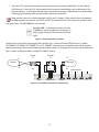
7. Connect a monitoring device to one of the Monitoring Ports, Monitor 1, 2, 3 or 4. Up to four
monitoring devices can be connected to a Filtered SINGLEstream™ at one time. The Link LEDs
indicate the monitoring device is connected properly and the speed of the link. When using a Fiber
Monitoring device make sure the Monitor Tx port is connected to the Rx port of the external
network device; and ensure that the Monitor Rx port is connected to the Tx port of the
external network device.
8. Connect the Remote Management Console to the Management Port. The Link LEDs indicate the
Remote Management Console is connected properly and the speed of the link.
Tx
Switch
Firewall
Router
Rx
Application
Monitor
Network
Internet
Monitor Ports
2
3
1
1A 1B
4
Tx Rx
2A 2B
Remote
Management
Console
Network TAPs
IDS
Forensic Analyzer
Collection
Figure 2.6 10/100/1000BaseT Network Tap using FSS-2000BT
12
2.2 Connecting a Fiber Network Tap
If you have a Filtered SINGLEstream™ model FSS-1000SX, FSS-1000LX, FSS-2000SX, FSS-2000LX, FSS-2000BT/
SX, or FSS-2000BT/LX, use the following procedure to connect a Fiber Network Tap.
Both Single mode (LX) and Multi-mode (SX) fiber Network Taps are connected the same way. In each case,
be sure to correctly cross-connect the Rx and Tx links between each pair of networked devices.
1. Identify the point within the network where you would like to connect a Network Tap.
The monitored point can be any point that is of particular interest to you. For example, you may
wish to monitor the data exchanged between the public Internet and your local intranet. You will
be able to connect an appropriate Network Tap to monitor any network traffic of interest.
TIP
2. Verify that the Filtered SINGLEstream™ is powered on by checking the Power LEDs on the front of the
Filtered SINGLEstream™.
3. Disconnect the fiber pair that connects the two external networking devices between which you
would like to connect the Network Tap. For example, to connect a Network Tap between the Internet
Router and the Firewall in the example network shown below, remove the fiber connection between
the Firewall and the Router.
Tx
Router
Firewall
Tx
Tx
Tx
Network
Internet
Rx
Rx
1A
1B
Rx
Rx
Figure 2.7 Fiber Network
4. Next, you must connect both the Router and the Firewall to the Filtered SINGLEstream™. To do this,
you will need two pairs of fibers.
13
5. First using pair of fiber cables, connect the Rx of the Router to the Tx of the Filtered SINGLEstream™
Network Tap 1 Port A. Then, use the other fiber in the pair to connect the Tx of the Router to the Rx of
the Filtered SINGLEstream™ Network Tap 1 Port A.
Router
Tx
Tx
Rx
Rx
Internet
Monitor Ports
2
1
3
4
Tx Rx
Tx Rx
1A
1B
Network TAP
Figure 2.8 FSS-1000LX with Network Tap 1A
6. Now make a similar connection between the Firewall and the Filtered SINGLEstream™ Network Tap 1
Port B as shown in the figure below. Again, be sure to connect the Tx of the Firewall to the Rx of the
Filtered SINGLEstream™, and the Rx of the Firewall to the Tx of the Filtered SINGLEstream™.
Firewall
Tx
Router
Tx
Tx
Tx
Internet
Network
Rx
Rx
Rx
Rx
Monitor Ports
1
Tx Rx
Tx Rx
1A
1B
Network TAP
Figure 2.9 FSS-1000LX with Network Tap 1A and 1B
14
2
3
4
7. Verify the LEDs are lit indicating that a network connection has been established. On the Filtered
SINGLEstream™, the Link LEDs are located on the front panel, immediately next to the Network Tap
port connections. A solid light indicates that a connection has been established at the stated speed.
A blinking light indicates that network traffic is detected on the link.
Fiber network taps can only be connected with SX and LX models. Fiber network taps only operate
at 1000 megabits per second. The BT/SX and BT/LX models have LEDs for slower port speeds which
only apply when 10/100/1000BaseT network taps.
TIP
1000
Tap Link LED - A solid light indicates the Fiber
or 1000BaseT network segment is connected. A
blinking light indicates the presence of network
traffic.
Figure 2.10 Fiber Network Tap Link LED
You have now successfully connected a Fiber Network Tap. Owners of Filtered SINGLEstream™ models
FSS-2000SX, FSS-2000LX, FSS-2000BT/SX, or FSS-2000BT/LX can connect a second Network Tap at another
desired monitoring point using the appropriate network media. An example of a network with two Network
Taps is shown in the figure below (model FSS-2000LX shown).
Tx
Router
Tx
Firewall
Tx
Tx
Internet
Network
Rx
Rx
Rx
Rx
1
Tx Rx
Tx Rx Tx Rx
Tx Rx
Figure 2.11 FSS-2000LX with Two Fiber Network Taps
15
Monitor Ports
2
3
4
8. Connect a monitoring device to one of the Monitoring Ports, Monitor 1, 2, 3 or 4. Up to four
monitoring devices can be connected to a Filtered SINGLEstream™ at one time. The Link LEDs
indicate the monitoring device is connected properly and the speed of the link. When using a Fiber
Monitoring device make sure the Monitor Tx port is connected to the Rx port of the external
network device; and ensure that the Monitor Rx port is connected to the Tx port of the
external network device.
9. Connect the Remote Management Network to the Management Port. The Link LEDs indicate the
monitoring device is connected properly and the speed of the link.
Firewall
Tx
Router
Tx
Tx
Tx
Internet
Tx
Network
Rx
Rx
Rx
Rx
Application
Monitor
Rx
Monitor Ports
2
1
3
Tx Rx
Tx Rx
1A
1B
Network TAP
!
4
Tx Rx
Remote
Management
Console
Make sure the Tx / Rx fiber
connections are made properly.
IDS
Forensic
Collection
Figure 2.12 Fiber Network Tap using FSS-1000LX
16
Analyzer
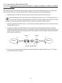
2.3 Connecting Multiple Tap Connections Using a Single Network Tap
The Filtered SINGLEstream™ FSS-2000BT/SX and FSS-2000BT/LX models provide the capability to connect
Fiber and/or 10/100/1000BaseT Network Taps. Notice that Network Tap 1 has two Port A connections and
two Port B connections. One A and B pair is for the 10/100/1000BaseT Network Tap, while the other A and B
pair is for the Fiber Network Tap. It is possible to connect both A and B pairs of a single Network Tap at the
same time; however if this is done, only one of the A and B pairs can be actively monitored. Through the
FLOWcontrol™ software, the user can select which of the physically connected taps is active.
In the figure below, Network Tap 1 of an FSS-2000BT/LX model is connected to two physical networks. The
hardware associated with Network Tap 1 can only be used to connect one active Network Tap at a time. In
the setup below, only one of the connected network links can be actively monitored.
Router
Firewall
Switch
Network 1
Resource 1
Router
Tx
Firewall
Tx
Tx
Tx
Resource 2
Network 2
Rx
Rx
Rx
1
Rx
Tx Rx
Monitor Ports
2
3
4
Tx Rx
Network Tap
Figure 2.13 FSS-2000BT/LX Application
By default, the 10/100/1000BaseT Network Tap is the network link that is actively monitored. So, in the
example above, Link 1 (the link between Resource 1 and Network 1) would be monitored. Link 2 (the
link between Resource 2 and Network 2), while connected to the Filtered SINGLEstream™, would not be
monitored in any way by default. Making both sets of connections is not a problem, though, because
the Filtered SINGLEstream™ will allow the normal network traffic to pass across both links. Using the
FLOWcontrol™ software, the user can decide to stop monitoring the traffic on Link 1 and instead monitor the
traffic on Link 2. The user must only make simple configuration changes, which can be done remotely.
2.4 Verify Proper Network Connections
Once you have connected the desired Network Tap(s), verify that the normal network traffic is flowing across
the newly connected tap(s). Even when the Filtered SINGLEstream™ is not connected to a power source, the
original network link should function just as it did prior to connecting the Network Tap. Traffic will not flow
to the Monitor Ports until the Filtered SINGLEstream™ is configured using FLOWcontrol™. Check the status of
each of the external devices to ensure normal link connections indicators.
Now that your Network Tap has been connected, you are ready to begin configuring your Filtered
SINGLEstream™ to filter and route the desired network traffic to the specified monitoring devices.
17
3 Installing the FLOWcontrol™ Software
The FLOWcontrol™ software is used to configure the Filtered SINGLEstream™. This section covers the
installation of the FLOWcontrol™ software application.
1. Insert the FLOWcontrol™ CD into your computer’s CD-ROM drive.
2. Browse to your computer’s CD-ROM drive. Double click on the setup application to begin
installation.
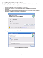
3. Some computers are protected against unverified applications. FLOWcontrol™ is a safe and secure
application. Click Install to continue the installation process.
Figure 3.1 FLOWcontrol™ Security Warning
4. A progress bar shows the status of the installation.
Figure 3.2 FLOWcontrol™ Installation Status
18
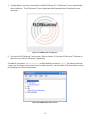
5. Congratulations, you have successfully installed FLOWcontrol™. FLOWcontrol™ starts automatically
after installation. The FLOWcontrol™ icon is displayed while the application is launched on your
computer.
Figure 3.3 FLOWcontrol™ Startup Icon
6. You are at the FLOWcontrol™ main screen. Refer to Section 5, Using the FLOWcontrol™ Software, to
learn how to use the FLOWcontrol™ application.
The default username is Administrator and the default password is admin. The Administrator has
“super-user” privileges and can limit access by other accounts. See the Utilities Pull-down Menu section
for changing user account information.
Figure 3.4 FLOWcontrol™ Main Screen
19
Quick Tips: Configuring the IP Address of a Filtered SINGLEstream™
■ You may want to record the IP address(es) of your Filtered SINGLEstream(s) ™ here for easy reference
in the future:
Location
Sub-Location
FSS Model Number
IP Address
■ You may want to record your Username and Password information here for easy reference in the
future:
USERNAME: ____________________________________
PASSWORD: ____________________________________
■ You may connect your PC to your Filtered SINGLEstream™
- With the provided serial cable & HyperTerminal
- With the provided serial cable & the FLOWcontrol™ software
- With a cross-connect LAN cable & the FLOWcontrol™ software
■ An agent stores the specific connection information that your PC uses to connect to a Filtered
SINGLEstream™.
■ Default agents allow for serial connections to the Filtered SINGLEstream™
■ Additional agents must be created to allow for LAN connections
■ This section provides information on configuring the IP address only. For more information
regarding the creation of connection agents see Section 5.1.
■ The default IP Address for the Filtered SINGLEstream™ is: 192.168.1.1. This address will most likely
need to be modified in order for the Filtered SINGLEstream™ to be available via your local network.
■ The default user name is Administrator, and default password is admin
20
4 Configuring the IP Address of a Filtered SINGLEstream™
The Filtered SINGLEstream™ is assigned an IP address by default. It is likely that the IP address must be
changed before the Filtered SINGLEstream™ can be integrated into your local network. . A new IP address
can be assigned using Microsoft’s HyperTerminal or FLOWcontrol™.
The initial setup, according to the Quick-Installation Guide, may have already been completed. If
your Filtered SINGLEstream™ already has an IP address for your network, please turn to Section 5,
Using the FLOWcontrol™ Software.
TIP
If you need to modify the IP address of your Filtered SINGLEstream™, continue with one of the Configurint
the IP Address sections below.
4.1 Configuring the IP Address – HyperTerminal
The IP address of your Filtered SINGLEstream™ can be configured via a serial connection. A serial connection
can be made with Microsoft’s HyperTerminal application that is typically available on Windows PCs.
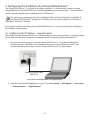
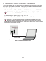
1. First, you must connect your PC and your Filtered SINGLEstream™. Using the provided cable
(Datacom Systems Cable #DRL434-6), connect the 9-pin end to the serial port on your PC, and
connect USB end to the serial port on your Filtered SINGLEstream™ as shown below:
Datacom Systems Cable
#DRL434-6
Figure 4.1 FSS Serial Connection using HyperTerminal
2. Open the HyperTerminal Application on your PC by selecting Start → All Programs → Accessories
→ Communications → HyperTerminal
21
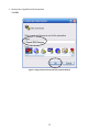
3. Name a New HyperTerminal Connection
Click OK.
Figure 4.2 HyperTerminal Connection Description Window
22
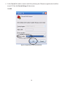
4. On the Connect To window, create a serial link by selecting the COM port assigned to the Serial Port
on your PC from the Connect Using pull-down menu.
Click OK.
Filtered SINGLEstream
Figure 4.3 HyperTerminal Connect To Window
23
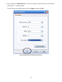
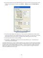
5. Next, configure the COM Properties. The correct settings to communicate with your Filtered
SINGLEstream™ are shown below.
Once all settings are configured correctly, click Apply, and then click OK.
Figure 4.4 HyperTerminal COM Properties Window
24
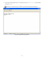
6. Login into the Filtered SINGLEstream™. The default user name is Administrator and the default
password is admin.
TIP
Sometimes it is necessary to press <ENTER> once to obtain the HyperTerminal prompt.
Figure 4.5 FSS HyperTerminal Login Window
25
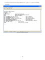
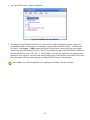
7. You are now connected to your Filtered SINGLEstream™ . Type HELP to see a list of available
commands.
Figure 4.6 FSS Commands Window
26
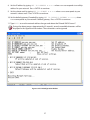
8. Set the IP address by typing SET IP ADDRESS x.x.x.x where x.x.x.x corresponds to a valid ip
address for your network. Press <ENTER> to continue.
9. Set the subnet mask by typing SET IP SUBNET x.x.x.x where x.x.x.x corresponds to your
network’s subnet mask. Press <ENTER> to continue.
10. Set the default gateway (if needed) by typing SET IP DEFAULT GATEWAY x.x.x.x, where
x.x.x.x corresponds to your network’s default gateway. Press <ENTER> to continue.
11. Type EXIT to save the network address changes and reboot the Filtered SINGLEstream™.
TIP
During the reboot process (approximately 45 seconds), several unreadable characters will be
displayed in the HyperTerminal window. These characters can be ignored.
Figure 4.7 FSS IP Configuration Window
27
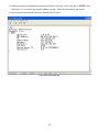
12. When the reboot is complete, the stream of characters will stop. At this time, press <ENTER>, and
then type SHOW to review the network address settings. Verify that the settings are correct.
13. Disconnect the Serial Cable from your Filtered SINGLEstream™
Figure 4.8 FSS Show Window
28
4.2 Configuring the IP Address – FLOWcontrol™, Serial Connection
The IP address of the Filtered SINGLEstream™ can also be modified using a serial connection with the
FLOWcontrol™ software application. Using FLOWcontrol™ with a serial connection is only recommended
during initial configuration.
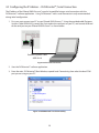
1. First, you must connect your PC to your Filtered SINGLEstream™. Using the provided cable (Datacom
Systems Cable #DRL434-6), connect the 9-pin end to the serial port on your PC, and connect USB end
to the serial port on your Filtered SINGLEstream™ as shown below:
Datacom Systems Cable
#DRL434-6
Figure 4.9 FSS Serial Connection
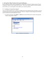
2. Start the FLOWcontrol™ software application.
3. From the main FLOWcontrol™ Main Window, expand Local Connectivity, then select the local COM
port you are using on your PC.
Figure 4.10 FLOWcontrol™ Local Connectivity
29
4. To connect using your PC’s COM port, select Agent → Connect. You will be presented with the login
screen. The default user name is Administrator and the default password is admin.
Figure 4.11 FLOWcontrol™ Login Window
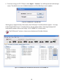
After logging in (approximately 150 seconds), the FLOWcontrol™ the Main Window appears. An image
of the Filtered SINGLEstream™ is displayed across the top of the window. The image displayed will
automatically update to the correct image. An FSS-2000BT/SX is shown below.
TIP
The FLOWcontrol™ activity is shown across the bottom of the Main Window.
Figure 4.12 FLOWcontrol™ Main Window Connected to an FSS-2000BT/SX
30
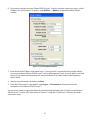
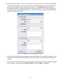
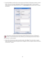
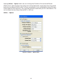
6. To correctly integrate your new Filtered SINGLEstream™ into your network, you must assign it a valid
IP address for your network. To do this, select Utilities → Options to open the Product Options
window.
Figure 4.13 Product Options Window
7. Enter the desired IP address and subnet mask. If your network is segmented into multiple subnets,
you may provide the Filtered SINGLEstream™ with a default gateway (such as the IP address of a local
router) to use when communicating with non-local devices. If you don’t need a default gateway,
leave it blank.
8. Save the new information by clicking on Save.
9. From the FLOWcontrol™ main window select Agent → Disconnect to disconnect the serial
connection to the Filtered SINGLEstream™.
You must now create an agent that allows for communication between your PC and your new Filtered
SINGLEstream™ via your LAN. Please refer to Section 5, Using the FLOWcontrol™ Software, to create a
connection agent.
31
4.3 Configuring the IP Address – FLOWcontrol™, LAN Connection
If your PC does not have a 9-pin serial connection, you can perform the initial configuration of the Filtered
SINGLEstream™ via an Ethernet LAN connection. To do this, you must be able to temporarily change the IP
Address of your PC and you must have a cross-connect LAN cable.
1. The default IP address of a Filtered SINGLEstream™ is 192.168.1.1 with a netmask of 255.255.255.0.
TIP
192.168.1.1 / 24 specifies the IP address (192.168.1.1) and the netmask ( / 24). The “/ 24” netmask
can also be written as “255.255.255.0”.
2. Temporarily set the IP address of your PC to 192.168.1.2 / 24.
3. Connect your PC to the Filtered SINGLEstream™ via a cross-connect LAN cable.
Some newer PCs may have Network Interface Cards that automatically detect when a crossconnection is necessary. In some cases, a cross-connect LAN cable will not work. If you have
trouble establishing a connection between your PC and the Filtered SINGLEstream™, you may want to try
using a normal (straight-through) LAN cable.
TIP
Ethernet Cable
Figure 4.14 FSS Management Port Connection
32
4. Start the FLOWcontrol™ software application.
Figure 4.15 FLOWcontrol™ Main Window
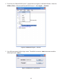
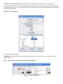
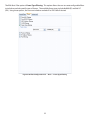
5. To configure a new Filtered SINGLEstream™ you must first define a connection agent. Agents are
connection profiles used by your PC to connect to various Filtered SINGLEstreams™. To create your
first agent, select Agent → Add to open the Product Configuration window and add a new agent.
When using your Filtered SINGLEstream™ the first time, create an agent with the default IP address of
the Filtered SINGLEstream™ (192.168.1.1). The IP address must be changed later to an appropriate IP
address for your network. You may enter the desired location & sub-location information at this time,
this information will help you distinguish one Filtered SINGLEstream™ from another.
!
The IP address must be changed later to an appropriate IP address for your network.
33
6. Enter the default IP Address (192.168.1.1) and Port for your new agent on the Product Configuration
window as shown below. Also you must enter a descriptive name for this connection agent. If you
are on the same network as your Filtered SINGLEstream™ , the Get Product button retrieves the
FSS model information. The location information will be user specific. If you will be installing and
configuring several new Filtered SINGLEstreams™, then you may wish to name this agent “New_FSS_
Install” so you can re-use it later.
Figure 4.16 FLOWcontrol™ Product Configuration Window
7. When all the information has been entered correctly, select Save. This creates the new agent. Once
a new agent is created, the agent will appear in the list of agents shown on the main FLOWcontrol™
window.
8. To connect to a Filtered SINGLEstream™ using an agent, expand the list of agents until the IP Address
and Port appear. Click on the desired Address (Port): and select Agent → Connect.
34
9. You will be presented with the login screen. The default username is Administrator and the
default password is admin.
Figure 4.17 FLOWcontrol™ Login Window
After logging in (approximately 8 seconds), the FLOWcontrol™ the Main Window appears. An image
of the Filtered SINGLEstream™ is displayed across the top of the window. The image displayed will
automatically update to the correct image. An FSS-2000BT/SX is shown below.
Figure 4.18 Main FLOWcontrol™ Window Connected to an FSS-2000BT/SX
35
10. To correctly integrate your new Filtered SINGLEstream™ into your network, you must assign it a valid
IP address for your network. To do this, select Utilities → Options to open the Product Options
window.
Figure 4.19 Product Options Window
11. Enter the desired IP address and subnet mask. If your network is segmented into multiple subnets,
you may provide the FSS with a default gateway (such as the IP address of a local router) to use when
communicating with non-local devices. If you don’t need a default gateway, leave it blank.
12. Save the new information by clicking on Save.
13. Select Agent → Disconnect to disconnect from the Filtered SINGLEstream™. The FLOWcontrol™
window should now be displayed.
Your Filtered SINGLEstream™ now has a unique IP address for your network. The agent needs to be updated
to allow for communication between your PC and your new Filtered SINGLEstream™. When initially created,
the agent made use of the default IP address of 192.168.1.1. You must change this IP address to the new
address you assigned to your Filtered SINGLEstream™. Please refer to Section 5, Using the FLOWcontrol™
Software, to update the connection agent.
36
5 Using the Filter Product Console Software
By now, you have created at least one Network Tap, installed the FLOWcontrol™ software on your PC, and
assigned an IP address to your Filtered SINGLEstream™. Now you are ready to define the routes and filters
that will allow you to send tapped network traffic to your monitoring devices.
5.1 Creating a Connection Agent
Once your Filtered SINGLEstream™ has been installed and correctly configured with an IP address, you must
create an agent on your PC using the FLOWcontrol™ software. An agent is a local configuration that allows
your PC to connect to the Filtered SINGLEstream™.
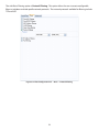
1. To create a new Agent, select Agent → Add from the main FLOWcontrol™ window to bring up the
Product Configuration window.
Figure 5.1 FLOWcontrol™ Main Window
37
2. Enter the IP address and Port for your new agent on the Product Configuration window as shown
below. Also you must enter a descriptive name for this connection agent. If you are on the
same network as your Filtered SINGLEstream™ , the Get Product button retrieves the FSS model
information.
Figure 5.2 FLOWcontrol™ Product Configuration Window
The Location and Sub-Location information will be displayed on the main FLOWcontrol™
window. Using descriptive terms here will allow you to easily keep track of all the Filtered
SINGLEstreams™ in your network.
TIP
3. When all the information has been entered correctly, select Save. This creates the new agent.
Once a new agent is created, the agent names will appear in the list of agents shown on the main
FLOWcontrol™ window.
38
4. To connect to a Filtered SINGLEstream™, expand the list of agents on the Main Window. Select the
Address (Port): of the desired Filtered SINGLEstream™. Select Agent → Connect.
Figure 5.3 FLOWcontrol™ Agent → Connect
5. You will be presented with the login screen. The default username is Administrator and the
default password is admin.
Figure 5.4 FLOWcontrol™ Login Window
39
After logging in, the FLOWcontrol™ the Main Window appears. An image of the Filtered SINGLEstream™
is displayed across the top of the window. The image displayed will automatically update to the correct
image. An FSS-2000BT/SX is shown below.
Figure 5.5 FLOWcontrol™ Main Window Connected to an FSS-2000BT/SX
40
5.2 Pull-down Menus
Upon login, the user is presented with the main FLOWcontrol™ window. Six pull-down menus that control
basic functions are always available across the top of the FLOWcontrol™ main window. The pull-down
menus (File, Agent, Filter, Control, Utilities, and Help) are described in this section.
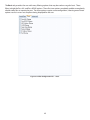
5.2.1 File Pull-down Menu
The File pull-down has one option, Exit, which closes FLOWcontrol™
Figure 5.6 File Pull-down Menu
5.2.2 Agent Pull-down Menu
The Agent pull-down allows the user to open and close the connection between the PC and the Filtered
SINGLEstream™.
Agent → {Connect, Disconnect}
Figure 5.7 Agent Pull-down Menu
41
5.2.3 Filter Pull-down Menu
The Filter pull-down is used with the Filter Configuration tab to open, save, import and export filters.
External filter files are stored as *.rec files (default file is filt.rec) and can only be used by the FLOWcontrol™
software application. By exporting your filter definitions to a file, you could re-use them when you
connected to another Filtered SINGLEstream™ device.
Filter → Open and Save are used to open and save both basic and advanced filters. These selections are
only available when the Filter Configuration → Basic or Advanced tab is selected.
Filter → Import is used load filters saved on your PC. Filter → Export is used save the filters you create on
your PC.
Filter → {Open, Save, Filter Definitions → {Import, Export to File} }
Figure 5.8 Filter Pull-down Menu
5.2.4 Control Pull-down Menu
The Control pull-down allows the user to apply new configuration settings to the connected Filtered
SINGLEstream™ or readback the current settings from the connected Filtered SINGLEstream™. The
configuration settings in question are dictated by the tab selected (Operational, Port Configuration, Filter
Configuration, etc).
Control → {Apply, Readback}
Figure 5.9 Control Pull-down Menu
42
5.2.5 Utilities Pull-down Menu
The Utilities pull-down allows the user to customize the connected Filtered SINGLEstream™.
Figure 5.10 Utilities → Upgrade Pull-down Menu
Selecting Utilities → Upgrade allows the user to upgrade the operational software files used by the Filtered
SINGLEstream™. The user may select to upgrade files for the Micro-Processor or for the Filter Engine. These
actions should only be taken at the direction of Datacom Systems Technical Support personnel.
43
Selecting Utilities → Options allows the user to change the IP address of the connected Filtered
SINGLEstream™, direct the Event Log (Syslog) to an external destination, require login access be granted
locally from the Filtered SINGLEstream™ or from a remote Radius Server, and define the value of the time
stamps applie to Event Log entries. The system data and time are based on your PC’s date and time. The
user can adjust the time stamps if desired (EST vs. GMT etc).
Utilities → Options
Figure 5.11 Utilities → Options Menu
44
The Utilities→ User Accounts option allows the user to define new login accounts, modify existing
accounts, and add personal contact information to existing accounts. For each account, the Administrator
can define access rights. In this manner, the Administrator can limit what configuration options are available
to certain login accounts.
Utilities → User Accounts
Figure 5.12 Utilities → User Accounts Pull-down Menu
5.2.6 Help Pull-down Menu
The Help pull-down provides links to information that may assist you while you are using your Filtered
SINGLEstream™.
Help → {About, Quick Connect Guide, User Guide, Website}
Figure 5.13 Help Pull-down Menu
45
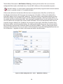
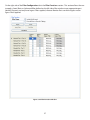
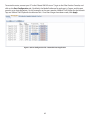
5.3 Configuration Tabs
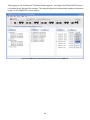
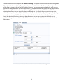
5.3.1 Operational Tab
From the Operational Tab, the user can check the current status of the Network Tap and Monitor Ports
available on the connected Filtered SINGLEstream™ by clicking the Readback button. The user must
click Readback to view the status of the connected Filtered SINGLEstream™. The user can change the
configuration by making changes and clicking the Apply button. The window is split into three sections:
Summary, Aggregation, and Filters.
The Summary section allows the user to visualize the number of Network Tap and Monitor Ports available.
Ports on the Filtered SINGLEstream™ are not configurable – each port is a part of a Network Tap or it is a
Monitor Port. Network Taps consist of A and B ports. All FSS models have Network Tap 1 with ports 1A and
1B; FSS-2000 models also have a second Network Tap with ports 2A and 2B. All models have 4 Monitor Ports.
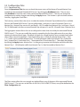
The Aggregation section allows the user to configure the routes that are used by the connected Filtered
SINGLEstream™. The user can modify the routes by expanding the list of possible routes for a port, then
selecting the desired check-boxes. By default, the ports for a single Network Tap are routed to each other
(these routes cannot be modified). In the figure below, Ports 1A and 1B make up Network Tap 1. Ports
1, 2, 3, and 4 are the available Monitor Ports. To route full-duplex traffic from Network Tap 1 to Monitor
Port 1, expand Port 1A and select Port 1. Then expand Port 1B and select Port 1. Then apply the changes
by clicking the Apply button. Monitor Port 1 is then going to receive the full-duplex network traffic from
Network Tap 1. All full-duplex traffic from Network Tap 1 is then forwarded to Monitor Port 1.
Figure 5.14 Operational Tab
The Filter section allows the user to apply any defined filter to any of the ports of the connected Filtered
SINGLEstream™. The user can set the filters to PASS-ALL, PASS-NONE,TCP Reset, or any filter defined on the
Filter Configuration tab.
46
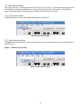
5.3.2 Port Configuration Tab
The Port Configuration tab allows the user to view or modify the port settings for all the available ports of
the connected Filtered SINGLEstream™. The Port Name, Media, and Port Speed can all be selected by the
user. FSS-2000BT/LX and FSS-2000BT/SX models have both fiber and copper media available for all ports,
including the Network Tap ports. Other models only have both fiber and copper media available for the
Monitor Ports. In each case, Copper is the default media type. To use a fiber connection for a port that
allows for both media types, you must access the Port Configuration and modify the Media Preference to
Fiber. The Port Type cannot be modified, as it is dependent upon which model of Filtered SINGLEstream™
you are connected to.
Be sure that the correct speed setting is used consistently across Network Taps. Both the A and
B ports of any Network Tap must have the same speed setting! Also be sure to only send an
appropriate amount of traffic to any connected monitoring device. A 10BaseT network analyzer cannot
handle all (unfiltered) traffic from both sides of a full-duplex 100BaseT Network Tap. If you direct more traffic
to a device than its link can handle, your monitored traffic will suffer from randomized packet loss.
TIP
The Readback button allows the user to view the current settings of the connected Filtered SINGLEstream™,
while the Apply button allows the user to send new configurations to the connected Filtered
SINGLEstream™.
Figure 5.15 Port Configuration Tab
47
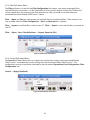
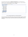
5.3.3 Filter Configuration Tab
The Filter Configuration tab provides the user with many filtering options. The screen is split into two
sections. On the left side, Saved Filters, Basic, and Advanced tabs are available. Each allows the user
to configure specific kinds of filters. On the right side, the Filter Functions section provides a tabular
representation of the filters applied to each port as ingress and/or egress filters.
The Saved Filters tab allows the user to select a filter that has been defined previously. Any saved filter can
be selected, and then applied to one of the ports of the connected Filtered SINGLEstream™.
Figure 5.16 Filter Configuration Tab → Saved Filters
48
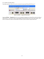
The Basic tab, provides the user with many filtering options that may be used on a regular basis. These
filters include the Pass-ALL and Pass-NONE options. These first two options completely enable or completely
disable traffic flow to a particular port. The other options require some configuration; selecting one of these
options results in a new set of options being displayed for the user.
Figure 5.17 Filter Configuration Tab → Basic
49
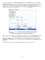
The third Basic Filter option is MAC Address Filtering. Selecting this box allows the user to create a
configurable filter based on the Media Access Control (MAC) Addresses of the networked computers.
TIP
The MAC Address is a unique 48-bit unique address permanently assigned to each network interface
card; it is typically written as 12 hexadecimal digits.
A filter can be defined to Include the traffic that meets the requirements of the filter, or the filter can
be defined to Exclude the traffic that meets the requirements of the filter. A filter can be defined for a
single MAC address or for a range of MAC addresses. The Source Address (the sending machine) and the
Destination Address (the intended recipient) can be configured separately. Selecting a Single address of
Any applies the filter to all detected traffic. After creating an Include/Exclude- Source-Destination rule, the
user can Add the rule. Multiple rules can be created and added. The Arrow selection box allows the user
to quickly change a defined rule. By default, the arrow points to the right, which filters for packets from
the Source Address to the Destination Address. By selecting the left-pointing arrow, the user can quickly
filter for packets sent from the Destination Address to the Source Address. Lastly, by selecting the arrows
pointing in both directions, the user can create a rule that looks for any packet exchanged between the two
sets of Addresses – regardless of which is the source and which is the destination.
Figure 5.18 Filter Configuration Tab → Basic → MAC Address Filtering
50
The fourth Basic Filter option is VLAN Filtering. Using this option, the user can create configurable filters
that include or exclude traffic based on the VLAN ID assigned to the Source of the network traffic. Rules can
be created for single IDs or for a range of IDs. Multiple rules can be created and applied as a single filter.
Figure 5.19 Filter Configuration Tab → Basic → VLAN Filtering
51
The fifth Basic Filter option is Frame Type Filtering. This option allows the user to create configurable filters
to include or exclude specific types of frames. The available frame types include 0x0800 (IP) and 0x8137
(IPX). Using these options, the user can include or exclude IP or IPX traffic if desired.
Figure 5.20 Filter Configuration Tab → Basic → Frame Type Filtering
52
The sixth Basic Filtering option is Protocol Filtering. This option allows the user to create configurable
filters to include or exclude specific network protocols. The network protocols available for filtering include
TCP and UDP.
Figure 5.21 Filter Configuration Tab → Basic → Protocol Filtering
53
The seventh Basic Filtering option is IP Address Filtering. This option allows the user to create configurable
filters that include or exclude traffic based on the source and destination IP addresses. The configuration
of this filter is similar to that of the MAC Address Filtering. The user can create multiple rules; each rule can
include the traffic that meets the filter requirements, or exclude the traffic that meets the filter requirements.
The Source and Destination addresses can be a single IP address, or a range of IP addresses. The Arrow
selection box allows the user to quickly change a defined rule. By default, the arrow points to the right,
which filters for packets from the Source Address to the Destination Address. By selecting the left-pointing
arrow, the user can quickly filter for packets sent from the Destination Address to the Source Address.
Lastly, by selecting the arrows pointing in both directions, the user can create a rule that looks for any
packet exchanged between the two sets of Addresses – regardless of which is the source and which is the
destination.
Figure 5.22 Filter Configuration Tab → Basic → IP Address Filtering
54
The eighth and final Basic Filtering option is Port Filtering. With this option, the user can create
configurable filters that include or exclude traffic based on the Source and Destination Ports. The user can
create multiple rules. Each rule can include the traffic that meets the filter requirements, or exclude the
traffic that meets the filter requirements. The Source and Destination can include a single port number or a
range of port numbers. The Arrow selection box allows the user to quickly change a defined rule. By default,
the arrow points to the right, which filters for packets from the Source Address to the Destination Address.
By selecting the left-pointing arrow, the user can quickly filter for packets sent from the Destination Address
to the Source Address. Lastly, by selecting the arrows pointing in both directions, the user can create a rule
that looks for any packet exchanged between the two sets of Addresses – regardless of which is the source
and which is the destination.
Figure 5.23 Filter Configuration Tab → Basic → Port Filtering
55
The Advanced filter tab should only be used to create very specific filters. The Advanced tab provides the
user with the ability to filter network traffic based on the bit masks of the individual frames. Within any
frame, the user can add a rule for the value of any byte within the frame. The rules must be defined at offsets
of whole words. Rule 1 and Rule 2 both allow for data filters for the bytes at offsets of 0 through 63. In the
figure below, a filter has been added that requires the fifth byte of data (offset by 4 bytes) must represent
a value of 0x1A or less. To add such a rule, select the desired byte, right click, and then select Add. The
Binary Mask can be used to limit the filter to consider only a portion of the selected byte. A “1” in the Binary
Mask includes that bit against the filter value, while a “0” excludes that bit from consideration. For example,
a Binary Mask of “00001111” would result in the last four bits of the selected byte being compared to the
value of 0x1A. A single filter can be defined for each byte. Before creating an Advanced filter, be sure you
understand the structure of the data frames that you would like to filter.
TIP
For a closer look at the structure of some standard frames, turn to Appendix A.
Figure 5.24 Creating a Rule Using the Filter Configuration Tab → MAC Address Filtering
56
On the right side of the Filter Configuration tab is the Filter Functions section. This section allows the user
to apply a Saved, Basic, or Advanced filter defined on the left side of the window to any appropriate port.
Network Tap ports can only have Ingress Filters applied, whereas Monitor Ports can have Ingress and/or
Egress Filters applied.
Figure 5.25 Filter Functions Window
57
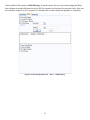
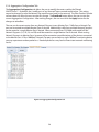
5.3.4 Aggregation Configuration Tab
The Aggregation Configuration tab allows the user to modify the routes used by the Filtered
SINGLEstream™. By default, the A and B ports of any Network Tap are routed to each other. This setting
cannot be changed, or else the Network Tap would cause a break in the network. The Filter Product Console
software does not allow the user to make this change. The Readback button allows the user to view the
current Aggregation Configuration. After making changes, the user must click the Apply button for the
changes to take affect.
The user can also create routes from any Network Tap port to any Monitor Port. Traffic from a Network Tap
port can be routed to multiple Monitor Ports if desired. Additionally, traffic from multiple Network Tap ports
can be routed to a single Monitor Port if desired. When connected to an FSS-2000 series model, all four
Network Tap ports (1A, 1B, 2A, and 2B) could be routed to a single Monitor Port if desired. When routing
Network Tap ports to Monitor Ports, be aware of the connection speed limitations of the devices connected
to the Monitor Port. If four 1000BaseT Network Tap ports are routed to a single 100BaseT monitoring device,
you may experience random packet loss. Random packet loss may lead to inconsistent network monitoring
results.
Figure 5.26 Aggregation Configuration Tab
58
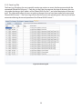
5.3.5 Event Log Tab
The Event Log Tab allows the user to quickly monitor any actions or events that have occurred with the
connected Filtered SINGLEstream™. Each entry in the Event Log captures the time of the event, the user
who made the change, the IP address of the Filtered SINGLEstream™, and a brief description of the event
itself. This information allows the user to track any changes that may have been made to the connected
Filtered SINGLEstream™. The Event Log will also alert the user to any operating errors that may have been
encountered during the normal operation of the Filtered SINGLEstream™.
Figure 5.27 Event Log Tab
59
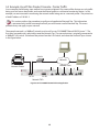
5.4 Example Use of Filter Product Console - Printer Traffic
As an example, the following steps outline how to create a Network Tap, create a filter that passes only traffic
being sent to a known destination, and route the filtered traffic to a connected monitoring device. In this
example, we are interested in monitoring the network traffic being sent to a network printer. The printer has
a fixed IP address of 10.10.5.5.
This section outlines the procedure to configure a hypothetical Network Tap. This information
is presented only to offer an example of how you could create a useful Network Tap. This exact
procedure may not apply to your network.
TIP
The example network is a 100BaseT network, and we will use an FSS-2000BT Filtered SINGLEstream™. The
first thing we need to do is physically create the Network Tap. The network printer is originally connected to
a 100BaseT LAN switch. Disconnect the printer from the LAN Switch, and create the Network Tap as shown
in the figure below.
Switch
Network
Network Printer
1
1A 1B
Monitor Ports
2
3
2A 2B
Network TAPs
Figure 5.28 FSS-2000BT Network Printer Application
60
4
Once the Network Tap has been created, the Network PCs can access the printer just like normal. The
Network Tap is passive and will not disrupt the network in any way. Next, connect the monitoring device,
a 10BaseT half-duplex LAN Analyzer in this case, to Monitor Port 1. Once all the physical connections have
been made and verified, you are ready to create the route and apply the filter.
Switch
Network
Network Printer
1
1A 1B
Monitor Ports
2
3
4
2A 2B
Network TAPs
Analyzer
Figure 5.29 FSS-2000BT Network Printer Application with Network Analyzer
61
To create the route, connect your PC to the Filtered SINGLEstream™, login to the Filter Product Console, and
click on the Port Configuration tab. By default, the Media Preference for each port is Copper, and the port
speed is set to Auto-Negotiate. For this example, set the port speed to 100BaseT Full-Duplex for the Network
Tap, and 10BaseT Full-Duplex for the Monitor Port. Once the changes have been made, click Apply.
Figure 5.30 Port Configuration Tab - Network Printer Application
62
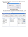
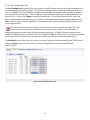
Next, create the route by clicking on the Aggregation Configuration tab. Ensure that both ports of
Network Tap 1, ports 1A and 1B, are configured to forward traffic to Monitor Port 1 as shown in the figure
below. Once you have made the configuration changes, click Apply.
Figure 5.31 Aggregation Configuration Tab - Network Printer Application
Now, a copy of the network traffic should be flowing to the connected LAN Analyzer. However, the 10BaseT
half-duplex LAN Analyzer connection cannot support all of traffic on the full-duplex 100BaseT network. To
prevent this over-subscription problem, a filter can be created that sends only the traffic of interest to the
LAN Analyzer.
63
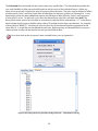
To create such a filter, click on the Filter Configuration tab. Select the Basic tab, and then check the IP
Address Filtering check-box. To view only that traffic that is being sent to the network printer, configure
the filter so that it includes traffic sent from any source IP address to the destination IP address of the
network printer. Once you have configured the rule, click Add. Under the Filter Functions section on the
right side of the window, name the new filter printer_traffic and click Save.
Figure 5.32 Filter Configuration Tab - Network Printer Application
Now the new filter is available, and can be applied to the various ports. Click on the Operational tab. The
new printer_traffic filter can be applied to the Network Tap Ports 1A and 1B from the pull-down
menu under the Filters section. Once configured correctly, click the Apply button. Also verify that the
Aggregation and Summary sections show the correction information by clicking the Readback button for
each section.
The LAN Analyzer should now only receive the traffic being sent to the network printer.
64
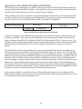
Appendix A Description of Frames and Packets
This section provides a description of an Ethernet frame and an Internet Protocol (IP) packet to aid the users
with the creation of Advanced bit mask filters. Advanced Filters are discussed in Section 5 of this document.
Typically, Layer 2 Ethernet frames are used to transport Layer 3 IP packets.
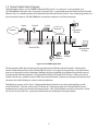
The figure below shows how an IP packet is encapsulated inside an Ethernet frame. Not all network traffic is
the same, and there are many available networking protocols. Because many networks rely upon Ethernet
at Layer 2 and IP at Layer 3, a brief description of each is provided in this Appendix.
Ethernet Frame Header
Frame Data
IP Header
Ethernet Frame
FCS / CRC
IP Packet Data
Figure A.1 Ethernet Frame Encapsulation of an IP Packet
On the next few pages, a more detailed description of the various fields that make up Ethernet frames and
IP packets is provided. There are many types of Ethernet in use throughout the world; the most common
types are Ethernet II and IEEE 802.3, although IEEE 802.3 SNAP and wireless IEEE 802.11 are also in use. The
IP packet is the basic packet format used to transmit and received data across local and wide-area networks.
Both Transmission Control Protocol (TCP) and User Datagram Protocol (UDP) messages are sent via IP
packets.
The Filter Product Console software allows the user to create Advanced Filter rules that are applied to the
first 64 bytes of any frame or packet. A full Ethernet frame header consists of 16 bytes (only 13 for the older
and shorter Ethernet II format). An IP packet header consists of an additional 23 bytes. To create a filter that
checks the Type of Transfer Protocol field for IP packets encapsulated in Ethernet frames, an offset of 25 bytes
would be used. An offset of 25 bytes means the filter would skip over the first 16 bytes of Ethernet frame
(the entire header), and then skip over the first 9 bytes of the IP packet header. The Type of Transfer Protocol
field is the 10th byte of the IP packet header, which means it has an offset of 9 bytes from the beginning of
the IP header. The Type of Transfer Protocol field is also the 26th byte of the Ethernet frame. Right clicking on
the offset of 25 bytes on the Filter Product Console’s Advanced Filter screen, and selecting Add allows for the
creation of a rule for the content of the Type of Transfer Protocol (in this case).
Using a similar method, it is possible to create an Advanced Filter that examines any combination of bits,
fields, and values within the first 64 bytes of any transmitted message. Before creating such a filter, you must
first understand the format of the protocol(s) in use.
65
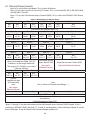
A.1 Ethernet Frame Formats
-
Bytes 0-13 are the Data Link Header. This is used in all formats.
Bytes 14-16 are the Logical Link Control (LLC) Header. This is used in the IEEE 802.3, IEEE 802.3 SNAP,
and IEEE 802.11 formats.
Bytes 17-21 are the Sub-Network Access Protocol (SNAP). This is used in the IEEE 802.3 SNAP format
only.
Table A.1 Bit Mapping of an Ethernet Frame
Byte 0
Bits
0-3
Byte 1
Bits
4-7
Byte 2
Byte 3
Bits
8-11
Bits
Bits
Bits
Bits
Bits
12-15
16-19
20-23
24-27
28-31
Destination MAC Address (Bytes 0-5)
Byte 4
Byte 5
Byte 6
Byte 7
Bits
Bits
Bits
Bits
Bits
Bits
Bits
Bits
32-35
36-39
40-43
44-47
48-51
52-55
56-59
60-63
Destination MAC Address (Bytes 0-5)
Source MAC Address (Bytes 6-11)
Byte 8
Byte 9
Byte 10
Byte 11
Bits
Bits
Bits
Bits
Bits
Bits
Bits
Bits
64-69
70-73
74-77
78-81
82-85
86-89
90-93
94-97
Source MAC Address (Bytes 6-11)
Byte 12
Byte 13
Byte 14
Byte 15
Bits
Bits
Bits
Bits
Bits
Bits
Bits
Bits
98-101 102-105 106-109 110-113 114-117 118-121 122-125
126-129
Frame Length
Destination Service
(does not include pre-amble, CRC, DLC
Access Point (DSAP)
Source Service Access Point (SSAP)
Addresses, or the Length Field itself.
Not used in
Not used in Ethernet II format
The range is 64-1518 Bytes, not used in
Ethernet II format
Ethernet II format)
Byte 16
Byte 17*
Bytes (18 ~ 1497)
Bits
Bits
Bits
Bits
130-133 134-137 138-141 142-145
Control
(specifies the type
of Frame being
Data
sent)
(this is where an IP header would begin…)
Not used in
Ethernet II format
4th to Last Byte
3rd to Last Byte
2nd to Last Byte
Last Byte
Last 32 Bits
Frame Check Sequence (FCS)
also known as
Cyclical Redundancy Check (CRC)
*Bytes 17 through 21 can be used to transmit the Sub-Network Access Protocol (SNAP) Header. If this is
used (only in IEEE 802.3 SNAP), the bytes 17, 18, and 19 are the Vendor’s Code, while bytes 20 and 21 are the
frame’s Ethertype. Using this format, the Data would begin with Byte 22.
66
A.2 IP Packet Format
Table A.2 Bit Mapping of an IP Packet
Byte 0
Bits
0-3
Bits
4-7
IP
IP
Header
Version
Length
Byte 4
Bits
Bits
32-35
36-39
Byte 1
Bits
8-11
Bits
12-15
Bits
64-69
Bits
70-73
Byte 5
Bits
40-43
Bits
44-47
Byte 9
Bits
74-77
Bits
78-81
Time To Live (TTL)
(Number of
permitted router
hops)
Type of Transfer
Protocol Used
Byte 12
Byte 13
Bits
98-101
Bits
102-105
Byte 16
Bits
130-133
Bits
134-137
Byte 20
Bits
162-165
Bits
166-169
Byte 24
Bits
194-197
Bits
198-201
Bits
16-19
Byte 3
Bits
20-23
Type of Service
(not used)
16-bit Packet Identification Number
Byte 8
Byte 2
Bits
24-27
Bits
28-31
Total Length of Datagram
(header & data)
Byte 6
Bits
48-51
Byte 7
Bits
52-55
Bits
Bits
56-59
60-63
Fragmentation Offset
Routing
(used when a router fragments the original packet
Flags
into multiple packets)
Byte 10
Byte 11
Bits
Bits
Bits
Bits
82-85
86-89
90-93
94-97
16-bit Header Checksum
Byte 14
Bits
106-109
Bits
Bits
Bits
Bits
110-113 114-117 118-121 122-125
32-bit Source IP Address
Byte 17
Byte 18
Bits
Bits
Bits
Bits
Bits
138-141 142-145 146-149 150-153 154-157
32-bit Destination IP Address
Byte 21
Byte 22
Bits
Bits
Bits
Bits
Bits
170-173 174-177 178-181 182-185 186-189
Options (if any) for the IP Packet
Byte 25
Byte 26
Bits
Bits
Bits
Bits
Bits
202-205 206-209 210-213 214-217 218-221
Start of Transmitted Data….
67
Byte 15
Bits
126-129
Byte 19
Bits
158-161
Byte 23
Bits
190-193
Byte 27
Bits
222-225
Appendix B HyperTerminal Commands
In Section 4 Connecting a PC to a Filtered SINGLEstream™, only the commands to configure the IP address of
the Filtered SINGLEstream™ are discussed. As shown in Section 4, you may use the supplied serial cable and
a PC equipped with a DB-9 serial port to configure your Filtered SINGLEstream™. The connection between
the PC and the Filtered SINGLEstream™ is depicted in the figure below.
Datacom Systems Cable
#DRL434-6
Figure B.1 FSS Serial PC Connection
To ensure proper communication, the HyperTerminal connection must use the same configuration settings
as the Filtered SINGLEstream™. Through HyperTerminal, configure the COM port of the PC as shown in the
figure below.
Figure B.2 HyperTerminal COM Properties Window
68
Once you have connected, many commands are available for use. In the following table, a brief description
of each of the commands and configuration options is provided.
TIP
The default user name is Administrator and the default password is admin.
Table B.1 FSS HyperTerminal Commands
Command
Syntax
Function
CLEAR SYSLOG
-
Clears the system log records stored on the Filtered
SINGLEstream™
EXIT
-
Terminates the HyperTerminal Session
HELP
-
Shows list of available commands / options
QUIT
-
Terminates the HyperTerminal Session
SET IP ADRESS
x.x.x.x
Sets the IP address of the Filtered SINGLEstream™
SET IP BROADCAST
x.x.x.x
Sets the broadcast address used by the Filtered
SINGLEstream™ (typically the 255 node)
SET IP DEFAULT
GATEWAY
x.x.x.x
Sets the IP address of the default gateway used by the
Filtered SINGLEstream™ to access non-local networks
(typically a local router)
SET IP SUBNET
x.x.x.x
SET TCP PORT
xxxxx
SHOW IP
-
Sets the IP subnet mask used for the local network (Typical
Class C network uses 255.255.255.0)
Sets the TCP port number used by the Filtered
SINGLEstream™. Port numbers range from 1 to 65535, with
many ports being reserved for well-known uses - Port 21 is
used for FTP and port 80 is used for HTTP. If you select a wellknown port number, you may experience minor network
problems.
Shows the current settings for the IP address, subnet mask,
and default gateway.
69
Appendix C Product Specification
Specifications for: FSS-1000 BT, LX, and SX models
FSS-2000 BT, LX, SX, BT/LX, and BT/SX models
Table C.1 Filtered SINGLEstream™ Product Specifications
Physical Specifications
Sizes: 3” (7cm) H x 18” (40cm) W x 9” (20cm) D
Unit Weight: 7 lbs (3.2 kg)
Network Tap Physical Connections
BT ports:
- RJ45 connector,
- Cat 5E cable,
- 10/100/1000 Mbps (auto sensing)
SX ports:
- Short-haul, Multi-mode fiber,
- 50 or 60.5 microns,
- 1000 Mbps
LX ports:
- Long-haul, Single Mode fiber,
- 9 microns,
- 1000 Mbps
Monitor Port Physical Connections
BT ports:
- RJ-45 connector,
- Cat 5E cable,
- 10/100/1000 Mbps (auto sensing)
Fiber ports:
- LC connector allowing for SX or LX
- 1000 Mbps
Power Specifications
Voltage: 100 – 240 VAC
Ampere: 1.5 A
Frequency: 50-60 Hz
Redundant Power Connections
Environmental Specifications
Operating Temperature: 32°F to +104°F (0°C to +40°C)
Storage Temperature: -22°F to +149°F (-30°C to +65°C)
Operating Humidity: Up to 95% non-condensing
70
Index
10/100/1000BaseT 2, 6, 47, 60
autosensing 47
801.11 65
frame description 66
802.3 65
frame description 66
A
Advanced Filters 56
Agent 32, 37
adding 32
connect using 32
creating 37
modifying 32
Aggregation 1, 46, 58
configuration 46, 58
configuration tab 58
Authentication 43, 68
local 43
radius server 68
Specification 70
File
filter, saved format 42
pull-down menu 41
Filter
advanced 55
basic 48–54
configuration 48
Filter Configuration Tab 48
advanced 56
basic 48–54
filter functions 57
saved 48
Frames 52, 65
description 65
filters 52, 56
H
Help 45
pull-down menu 45
HyperTerminal 21, 68
commands 68
connection settings 21, 68
connect using 21, 68
B
I
Basic Filters 48–54
Binary Mask 55
filters 55, 65
Broadcast
Setting the IP address 68
IEEE 802.11 65
802.11 66
802.2 SNAP 66
802.3 66
frame description 65
Installation 8, 18, 21, 29
configuration software 18
Filtered SINGLEstream 8, 21, 29
rack mounting 8
Internet Protocol (IP) 54, 65, 67
address filtering 54
configuring the address 21, 29, 31
default address 32
packet description 67
C
Connecting 21, 41
HyperTerminal 21
SW LAN 31
SW serial 29
Control 42
pull-down menu 42
D
Default Gateway 27, 31, 36, 43, 69
configuring 27, 31, 36, 43, 69
reviewing 43, 69
E
Ethernet 2, 65
autosensing 47
cross-connect cable 32
frame description 66
Ethernet II 65
frame description 66
Event Log 59
Exit 41, 69
F
Fiber 2
L
LAN 10, 31
connection 31
example 60
Link 2, 17, 47
Monitor Port LED 2
passive 2
Tap LED 2
Location Information 32
configuring 32
sub-location information 32
Login 32, 37, 42
default password 30
default username 30
Logout 41, 69
Long Haul Fiber 70
LX 1, 2, 70
71
long-haul fiber 70
model description 2
single mode fiber 2, 70
M
MAC Address 49
filtering 49
Management 6, 29, 31, 37
LAN connection 31
network 6, 29
remote access 6, 31
serial connection 29
Models 2, 70
descriptions 2, 70
Monitoring Device 60
connecting 47, 60
filtering 48
oversubscription 47, 60
Monitor Port 2, 6, 46, 47, 58, 60, 70
10/100/1000BaseT 2, 6, 47
fiber 2, 6, 47
Multi-mode 2, 6, 70
N
Netmask 27, 31, 32, 36, 42, 68
configuring 27, 31, 32, 36, 42, 68
reviewing the configuration 42, 68
Network Interface Card (NIC) 32, 50
connecting with 32
MAC address 50
Network Tap Port 2
numbering 5
types 4
O
Operational Tap 46
configuration 46
Options 31
configuration 35, 43
FSS models 2
P
Passive 5, 6, 60
10/100/1000BaseT Tap 5, 10
fiber tap 5, 11
Password 20
default 30
Port 2, 47, 55
filters 55
numbering 5
Port Configuration Tab 47
copper 47
fiber 47
port speed 47
Port Speed 47
Power 4
connections 5
LEDs 4
Printer 60
example tap 60
Protocol 53
description 65
filters 53
Q
Quit 69
R
Radius Server Authentication 42
Router 6, 11, 12, 16
example tap 6, 11, 12, 16
S
Saved Filters 48, 60
Serial 21, 29, 68
Hyperterminal commands 68
management port 2, 21, 29
PC - FSS Connection 21, 29
Short Haul Fiber 70
Single Mode Fiber 2, 70
Specification 70
environmental 70
physical 70
ports 70
power 70
Sub-location Information 37
location information 37
Subnet Mask 27, 31, 32, 36, 42, 68
Switch 6
example tap 6, 60
SX 2, 70
model description 2
multi-mode fiber 2
short-haul fiber 70
T
Tap 2, 60, 70
10/100/1000BaseT 2, 70
creating a network tap 60
fiber LX 2, 70
fiber SX 2, 70
passive 2
TCP 53, 65, 67, 68
IP packet description 67
TCP port filtering 53
well-known ports 68
U
UDP 53, 65, 67
IP packet description 67
USB 1, 21, 29
management port 21, 29
serial cable connection 21, 29
User Accounts 20, 30
72
login options 20
Username 20, 30
default 20, 30
Utilities 43
options 43
pull-down menu 43
software upgrades 43
user accounts 43
V
Virtual LAN (VLAN) 51
filters 51
73
Customer Service
This User’s Guide is designed to help you get to know your new Filtered SINGLEstream™ quickly and
easily. Datacom Systems Customer Service personnel are available weekdays from 8:30 AM to 5:00 PM EST.
Customer Service is available via telephone, facsimile, and E-mail. Outside of support hours, please leave a
voice message and Customer Service will return your call as soon as possible.
Mail
Datacom Systems, Inc.
Attention: Technical Support
9 Adler Drive
East Syracuse, NY 13057-1290
Telephone
+1 315-463-9541
FAX
+1 315-463-9557
E-mail
[email protected]
WWW
http://www.datacomsystems.com
Compliance Testing
CAUTION: Changes or modifications to this unit not expressly approved by the party responsible for
compliance could void the user’s authority to operate the equipment.
This equipment has been tested and found to meet the radiated and conducted emission limits for a Class A
product of EN 55022 to the European Community EMC Directive 89/336/EEC requirements.
This equipment has been tested and found to meet general immunity standard EN 61000-6-1:2001 for
residential, commercial and light industrial devices. This equipment has been tested to meet specific
immunity standards: EN 6100-4-2 for electrostatic discharge, EN 61000-4-3 for radiated susceptibility,
EN 61000-4-4 for electrical fast transient/burst, EN 61000-4-5 for surge, EN 61000-4-6 for conducted
susceptibility, EN 61000-3-2 for harmonic current, and EN 61000-3-3 for voltage fluctuations & flicker.
This equipment has been tested and found to meet the Low Voltage Directive 98/68/EEC.
74
Factory Warranty
Datacom Systems, Inc. (DSI) warrants the hardware and software which it supplies will be free from
significant defects in materials and workmanship for a period of (12) months for hardware and (90) days
for software from the date of delivery (Warranty Period), under normal use and conditions. In the event of
any such defect, you can return an item of defective hardware, freight prepaid, to DSI during the Warranty
Period, and DSI will repair or replace the defective equipment with an equivalent or better model and return
it to you, freight prepaid. If DSI determines that the equipment is not defective, it will return to you freight
collect. DSI shall have no responsibility for any deficiency resulting from accidents, misuse, modifications,
power disturbances (including use of a power supply not specified by DSI), or various forms of disaster e.g.
earthquakes, floods, etc.
Limitations on Liability
The warranties set forth above are exclusive and in lieu of all other warranties. Datacom Systems, Inc. (DSI)
makes no other warranties, expressed or implied, and DSI expressly disclaims all other warranties, including
but not limited to implied warranties of merchantability and fitness for a particular purpose. Moreover, the
provisions set forth above state DSI’s entire responsibility and your sole and exclusive remedy with respect
to any breach of warranty or contract.
No liability for consequential damages. Under no circumstances and under no theory of Liability shall DSI be
liable for costs of procurement of substitute products or services, lost profits, lost savings, loss of information
or data, or any other special, indirect, consequential or incidental damages, arising in any way out of the
sale of, use of, or inability to use, any DSI product or service, even if DSI has been advised of the possibility of
such damages.
Force Majeure
Datacom Systems, Inc. (DSI) will not be liable for any failure to perform due to unforeseen circumstances or
causes beyond DSI’s reasonable control, including, but not limited to acts of God, war, riot, embargoes, acts
of civil or military authorities, fire, flood, accidents, strikes, inability to secure transportation, facilities, fuel,
energy, labor, or materials.
Copyright
Copyright © 2006 by Datacom Systems, Inc. All rights reserved. Printed in the United States of America. No
Part of this publication may be reproduced, stored in a retrieval system, or transmitted, in any form or by any
means, electronic, mechanical, photocopying, recording, or otherwise, without the prior written permission
of Datacom Systems, Inc. To obtain this permission, write to the attention of the Datacom Systems, Inc. legal
department at 9 Adler Drive, East Syracuse, New York 13057-1290, or call 315-463-9541.
75