1
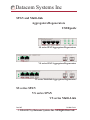
Datacom Systems Inc
SPAN and Multi-link
Aggregators/Regenerators
USERguide
SS series SPAN Aggregators/Regenerators
VS series SPAN Aggregators/Regenerators
VS series Multi-link Aggregators/Regenerators
SS series SPAN
VS series SPAN
VS series Multi-Link
June 2007
541-0106-U-A.01
© 2004-2007 by Datacom Systems Inc. All Rights Reserved.
Datacom Systems Inc
Copyright
Copyright © 2004-2006 by Datacom Systems, Inc. All rights reserved. Printed in the
United States of America. No part of this publication may be reproduced, stored in a
retrieval system, or transmitted, in any form or by any means, electronic, mechanical,
photocopying, recording, or otherwise, without the prior written permission of
Datacom Systems, Inc. To obtain this permission, write to the attention of the Datacom
Systems legal department at 9 Adler Drive, East Syracuse, New York 13057-1290, or
call 315-463-9541.
License Agreement
Notice To All Users: By using a Datacom Systems Inc SINGLEstream™ Link
Aggregator you agree to the terms set forth. No licenses, express or implied, are granted with respect to the technology described and Datacom Systems Inc retains all rights
with respect to the technology described herein. If applicable, you may return the
product to the place of purchase for a full refund.
Trademark Attribution
DS3 ACTIVEtap™, DS3switch™, Empowering Network Professionals™,
ETHERNETtap™, FDDIswitch™, FIBERsplitter™, FIBERswitch™, FIBERSWITCHGIGABITswitch™,
INSERTswitch™, INSERTunit™, LANswitch™,
system™,
™
™
MULTINETswitch , NETspan , PERMAlink™, PROline™, RMON SWITCHINGanalyzer™, SINGLEstream™, UNIVERSALswitch™, VERSAstream™, and WANswitch™ are trademarks of Datacom Systems, Inc. 1ST in Switching Solutions®,
DATACOMsystems®, LANclipper®, MANAgents®, and MULTIview® are registered
trademarks of Datacom Systems, Inc. All other registered and unregistered trademarks
are the sole property of their respective owners. All specifications may be changed
without notice.
Proprietary Notice
This document contains proprietary information about the SINGLEstream™ Link
Aggregator and is not to be disclosed or used except as authorized by written contract
with Datacom Systems, Inc.
SPAN and Multi-Link Aggregators/Regenerators • USERguide
4
Datacom Systems Inc
Compliance Testing
CAUTION: Changes or modifications to this unit not expressly approved by the party responsible for compliance could void the user’s authority to operate the equipment.
Certifications
This equipment has been tested and found to meet the radiated and conducted emission limits for a Class
A product of EN 55022 to the EMC Directive 89/336/EEC requirements.
This equipment has been tested and found to meet the immunity levels for Class 1 tested to level 2 for
EN 6100-4-2, level 3 for EN 61000-4-3, level 1 for EN 61000-4-4, and level 3 for EN 61000-4-5 to
the EN 50082-1 requirements and meets the Class A requirements for EN 61000-3-2 and EN 61000-33.
This equipment has completed the Product Safety Review and found to meet the Low Voltage Directive
72/23/EEC (1993) requirements.
NOTE: This equipment has been tested and found to comply with the limits for a Class A digital device,
pursuant to Part 15 of the FCC Rules. These limits are designed to provide reasonable protection against
harmful interference when the equipment is operated in a commercial environment. This equipment generates, uses, and can radiate radio frequency energy and, if not installed and used in accordance with the
instruction manual, may cause harmful interference to radio communications. Operation of this equipment
in a residential area is likely to cause harmful interference in which case the user will be required to correct
the interference at his own expense.
These explanatory labels are included in
the information for the user in accordance
with the requirements of IEC 60825-1.
CLASS 1 LASER PRODUCT
SPAN and Multi-Link Aggregators/Regenerators • USERguide
Datacom Systems Inc
5
Contents
What Shipped? . . . . . . . . . . . . . . . . . . . . . . . . . . . . . . . . . . . . . . . . . . . . . . . . . . . 6
Introduction . . . . . . . . . . . . . . . . . . . . . . . . . . . . . . . . . . . . . . . . . . . . . . . . . . . . . . 7
Attributes & Advantages . . . . . . . . . . . . . . . . . . . . . . . . . . . . . . . . . . . . . . . . . . . . 8
SINGLEstream™ SPAN SS-200 Series Aggregators/Regenerators Overview . . . . . 8
SS-200 Features & Benefits . . . . . . . . . . . . . . . . . . . . . . . . . . . . . . . . . . . . . . . 9
SS-200 Specifications . . . . . . . . . . . . . . . . . . . . . . . . . . . . . . . . . . . . . . . . . . 10
SS-200 Hardware Description . . . . . . . . . . . . . . . . . . . . . . . . . . . . . . . . . . . . 11
SS-200 Application & Hardware Installation . . . . . . . . . . . . . . . . . . . . . . . . . 12
VERSAstream™ SPAN Series Aggregators/Regenerators Overview . . . . . . . . . . . 14
VERSAstream™ SPAN Series Features & Benefits . . . . . . . . . . . . . . . . . . . . . 15
VERSAstream™ SPAN Series Specifications . . . . . . . . . . . . . . . . . . . . . . . . . 16
VERSAstream™ SPAN Series Hardware Description . . . . . . . . . . . . . . . . . . . 17
Application & Hardware Installation . . . . . . . . . . . . . . . . . . . . . . . . . . . . . . . 21
‘Dual-Homed Server Application . . . . . . . . . . . . . . . . . . . . . . . . . . . . . . . 21
Full Duplex aggregated Application . . . . . . . . . . . . . . . . . . . . . . . . . . . . . 22
Primary/Redundant Router Application . . . . . . . . . . . . . . . . . . . . . . . . . . 23
VERSAstream™ Multi-link Series Aggregators/Regenerators Overview . . . . . . . . 25
VERSAstream™ Multi-link Series Features & Benefits . . . . . . . . . . . . . . . . . . 26
VERSAstream™ Multi-link Series Specifications . . . . . . . . . . . . . . . . . . . . . . 27
VERSAstream™ Multi-link Series Hardware Description . . . . . . . . . . . . . . . . 28
Analyzing/Monitoring Gigabit EtherChannel . . . . . . . . . . . . . . . . . . . . . . . . . 31
Application & Hardware Installation . . . . . . . . . . . . . . . . . . . . . . . . . . . . . . . 32
Gigabit EtherChannel Application . . . . . . . . . . . . . . . . . . . . . . . . . . . . . . 32
VS-1028 with Taps Application . . . . . . . . . . . . . . . . . . . . . . . . . . . . . . . . 34
VS-1028 SPAN and In-line Application . . . . . . . . . . . . . . . . . . . . . . . . . . 36
VS-1610 kit Application . . . . . . . . . . . . . . . . . . . . . . . . . . . . . . . . . . . . . 38
Customer Service, World Wide Web . . . . . . . . . . . . . . . . . . . . . . . . . . . . . . . . . . 41
Warranty, Limits of Liability . . . . . . . . . . . . . . . . . . . . . . . . . . . . . . . . . . . . . 41
SPAN and Multi-Link Aggregators/Regenerators • USERguide
6
Datacom Systems Inc
What Shipped ?
SS series SPAN Aggregators/Regenerators
1 — SS-(200, 201, 202 or 203)
2 — Switching AC Adapters
2 — AC Power Cords
1 — Warranty Card
1 — QUICKinstall Guide
1 — USERguide
VS series SPAN Aggregators/Regenerators
1 — VS-(1022BT-BT, 1062BT, 1031BT, 1031BT-02, 1082, 1082LX-BT, 1082SX-BT,
1082SX-SX, 1041SX-SX or 1022SX-SX)
2 — Switching AC Adapters
2 — AC Power Cords
1 — Warranty Card
1 — QUICKinstall Guide
1 — USERguide
VS series Multi-link Aggregators/Regenerators
1 — VS-(1026BT-BT, 1028, 1028SX, 1046, 1046SX, 1412 kit or 1610 kit)
2 — Switching AC Adapters
2 — AC Power Cords
1 — Warranty Card
1 — QUICKinstall Guide
1 — USERguide
SPAN and Multi-Link Aggregators/Regenerators • USERguide
Datacom Systems Inc
7
Introduction
The SPAN and Multi-link Aggregator/Regenerators can combine data from multiple
Ethernet network segments into one stream of data. A single device, such as an
intrusion detection system, protocol analyzer, or network probe can receive the
aggregated data with just one network interface card (NIC).
The SPAN and Multi-link Aggregator/Regenerators also have additional monitor
ports, so multiple devices can receive the same data stream. This allows different
monitoring and analysis devices to collect data from the same network segments at
the same time, eliminating contention for access to the network.
Monitor more network traffic with fewer tools
Network administrators are no longer required to have a separate device for each
network segment to achieve simultaneous 24x7 monitoring of multiple links, nor do
they need to "switch" to a different segment each time they need to collect data
from it. The SPAN and Multi-link Aggregator/Regenerators simultaneously collects
data from multiple network segments and aggregates all the data before sending it
to the connected monitoring and analysis devices, expanding network visibility and
reducing the number of tools needed on the network. Fewer tools means lower
equipment and licensing costs. And, because the SPAN and Multi-link Aggregator/
Regenerators aggregates all the data before sending it to the connected network
device, you can always view the entire conversation even in asymmetric routing,
redundant, and load-balanced environments.
Enhanced security
The SPAN and Multi-link Aggregator/Regenerators enhances your security because
it allows you to see 100% of your network traffic. Total visibility means no missed
packets and no chance of missing a network attack due to SPAN/Mirror port oversubscription, traffic overflow, or many of the problems associated with traditional
monitoring methods.
Improved problem resolution time
Aggregation offers a complete view of the traffic. Instead of collecting and manually assembling trace or log files from separate tools on separate network segments,
the SPAN and Multi-link Aggregator/Regenerators can easily let security and analysis tools collect all the data they need in a single file. In security applications,
events and false positives are recorded fewer times. In all applications, data can be
analyzed faster than ever, which increases uptime and saves money.
SPAN and Multi-Link Aggregators/Regenerators • USERguide
8
Datacom Systems Inc
Attributes & Advantages
• Connect any device (protocol analyzers, probes, intrusion detection system, more)
for permanent simultaneous monitoring of multiple full-duplex links — eliminates
the need for network connectors to be disconnected and connected each time a segment needs to be monitored.
• Multipoint analysis enables you to seamlessly analyze a packet at multiple points in
your network with one tool - know exactly what is happening to data as it moves
through your network.
• View all the data from multiple network segments - allows you to monitor and analyze traffic from asymmetric routing paths, load-balanced applications, and redundant environments.
• Two monitor ports (additional-port models available) allow two devices to simultaneously monitor the same links, providing extended security and analysis options,
while eliminating contention for network access.
• Simple plug-and-play solution -requires no additional configuration or configuration
of external monitoring devices.
• Save money on recurring licensing fees and maximize your ROI by deploying fewer
network devices.
• Redundant power supply insures seamless monitoring even if the main power source
is unavailable.
• Easy to install and 1 U" space saving design.
• Free Technical Support throughout the lifetime of the product.
• 2-year limited manufacturers warranty on hardware.
• Datacom Customer Service personnel are available Monday through Friday from
8:30 AM to 5:30 PM EST. Support is available via phone, fax, e-mail, or website.
SINGLEstream™ SS-200 Series Overview —
Datacom Systems' SINGLE stream™ series SPAN Aggregator/Regenerator provides a
superior solution for 24x7 monitoring of full-duplex Ethernet links.
While traditional Ethernet taps might enable full-duplex monitoring of all traffic on
a network link, they transmit the data to the monitoring device (e.g. analyzer, IDS,
probe) in two separate half-duplex streams. Not only does this require the monitoring device to have two network interface cards (NIC), it also requires that the device
be capable of combining and processing both streams of data in order to monitor
both sides of the conversation. Not all monitoring devices have that capability.
SPAN and Multi-Link Aggregators/Regenerators • USERguide
Datacom Systems Inc
9
The SINGLE stream™ series SPAN Aggregator/Regenerator faultlessly combines the
two data streams, allowing any connected monitoring device to receive a full-duplex
stream of data with one NIC.
Additionally, the SINGLE stream™ series SPAN Aggregator/Regenerator provides a
unique feature to help manage network resources - a second monitor port. With an
extra monitor port, two devices (such as an analyzer and an intrusion detection
device) can receive the same full-duplex transmission, so there will never be contention for access to the network link.
Although ideal for placement in networks where utilization is consistently under
50% on each side, the SINGLE stream™ series SPAN Aggregator/Regenerator can
help prevent data overload and dropped packets due to traffic "bursts" - sudden, temporary increases in bandwidth utilization. A built-in memory buffer can manage
overflows in data transmission and can allow seamless continuity of full-duplex
monitoring.
Just like all of Datacom Systems' tap products, the SINGLE stream™ series SPAN
Aggregator/Regenerator is completely non-intrusive. The SINGLE stream™ series
SPAN Aggregator/Regenerator redundant power supply design has been thoroughly
tested. Even if power is lost to the tap, network traffic will continue to flow uninterrupted.
SS-200 Features & Benefits
• Simple plug-and-play solution – requires no additional configuration of external monitoring devices.
• Connect any protocol analyzers, probes, intrusion detection systems and such for permanent In-Line monitoring of full-duplex links — eliminates the need for network connectors to be disconnected and connected each time a segment needs to be monitored.
• Proven industry leading, non-intrusive, fault-tolerant – will not interfere with data.
• Operates at 10 Mbps or 100 Mbps and supports full-duplex and half-duplex auto-negotiation.
• Two monitor ports allow two devices to simultaneously monitor the same link, providing extended security and analysis options, while eliminating contention for network access.
• Memory buffer manages traffic burst exceeding 100% of a single NIC utilization preventing data overload, dropped packets, and maintains continuity of full-duplex monitoring.
• Redundant power assures uninterrupted monitoring by eliminating power single point of failure — seamless monitoring even if the main power source is unavailable.
• Easy to install – optional rack mount available in two models, either 3 unit rack mount chassis (RMC-3)
1U high or 14 unit rack mount chassis (RMC-14) 4U high.
SPAN and Multi-Link Aggregators/Regenerators • USERguide
10
Datacom Systems Inc
SS-200 Specifications
PORT SPEED
SINGLEstream™ NETWORKMb
SS-200
SS-201
SS-202
SS-203
2(10/100BT)
2(100BT)
2(10/100BT)
2(100BT)
MONITOR PORT SPEED
Mb
2(10/100BT)
2(100BT)
2(10/100BT)
2(100BT)
Feature
TCP Reset
NO
NO
YES
YES
Optional
Rack Mount
RMC-3
RMC-3
RMC-3
RMC-3
Specification
Channel
Cable Type
Port Connectivity: NETWORK A
NETWORK B
TAP 1 A/B
TAP 2 A/B
Two SPAN
CAT 5E
RJ45
RJ45
RJ45
RJ45
Distance Limit
100 meter maximum length between network end-points.
Tap, typically 1 meter.
Power Requirements
Operating Temperature
Storage Temperature
Humidity
Dimensions
Two external power supplies 5 VDC, 1 A
0O to 40O C (32O to 104O F)
-30O to 65O C (-22O to 149O F)
Less than 95O C non-condensing
Weight
1.10" (H) x 5.75" (W) x 5.75" (D)
(includes RMC-3 panel bracket)
28 mm (H) x 146 mm (W) x 146 mm (D)
Unit - 12 ounces; Shipping - 2 pounds
SPAN and Multi-Link Aggregators/Regenerators • USERguide
Datacom Systems Inc
11
SS-200 Hardware Description — Figure 1 illustrates the SS-200 series SPAN
Aggregator/Regenerator front panel. This is the location for all cable connections and status LEDs.
Figure 1 - SS-200 Front Panel and functional diagram
An explanation of each front panel legend follows:
NETWORK A, B: These ports are RJ45 connectors used for network SPAN connection.
TAP 1 A/B and 2 A/B: These RJ45 connector ports are cabled to the NIC MONITOR card Port RJ45 connectors of each network monitoring tool.
LINK: The NETWORK-A LINK LED illuminates indicating link has been established between the NETWORK A
connector and NETWORK A device. The NETWORK-B LINK LED illuminates indicating link has been
established between the NETWORK B connector and NETWORK B device. The TAP 1 LINK LED illuminates indicating link has been established between the TAP 1 connector and monitoring device NIC (network interface card.) The TAP 2 LINK LED illuminates indicating link has been established between the
TAP 2 connector and monitoring device NIC (network interface card.)
ACT: The NETWORK A and NETWORK B ACT LEDs illuminate as data is passed back and forth between the
NETWORK A and NETWORK B devices. The TAP 1 ACT LED illuminates as data is passed to the TAP 1
monitoring device. The TAP 2 ACT LED illuminates as data is passed to the TAP 2 monitoring device.
POWER: The POWER LED illuminates indicating power is on.
SPAN and Multi-Link Aggregators/Regenerators • USERguide
12
Datacom Systems Inc
SS-200 Application & Hardware Installation —
The SS-200 is used primarily in conjuction with two SS-100s to monitor and anlaysis Primary and Redundant Distribution Networks. Figure 2 depicts a typical set of
monitoring tools attached to a primary circuit that automatically switch to the redundant circuit allowing uninterrupted monitoring using only one network interface card (NIC) for each
monitoring device to see the combined traffic.
Figure 2 - SS-200 Connectivity Diagram
To connect the SS-200 into the network, refer to FIGURE 3 and follow these steps:
Step 1. Two power supplies are provided for the SINGLEstream™ SS-100 and one power supply for the SINGLEstream™ SS-200. Use of the second power supply is strongly recommended for the SINGLEstream™ SS-100 to assure uninterrupted monitoring.
Connect both power supply barrel connectors into the POWER 1 and 2 ports, respectively, of the SINGLEstream™ SS-100. Plug the power Supplies into the external
power source, furthermore, connecting the second power supply to a different external
power source circuit than the first power supply eliminates power as a single point of
failure. The POWER 1 and 2 LEDs illuminate indicating power 1 and 2, respectively,
are on. Either LED not illuminated indicates a defective power source and immediate
replacement is required to insure redundant power integrity.
IMPORTANT: The maximum length of 100 meters must not be exceeded between end-points.
Step 2. Designate one SINGLEstream™ SS-100 primary and the other redundant. Connect the
primary network cables to the primary SINGLEstream™ SS-100 RJ45 port NETWORK A
connector. The NETWORK-A LINK LED illuminates indicating link has been established
between the NETWORK A connector and primary NETWORK A device.
NOTE: Let the “LINK” LED be your guide. If you are properly connected, NETWORK-A and NETWORK-B “LINK” LEDs remain illuminated simultaneously.
SPAN and Multi-Link Aggregators/Regenerators • USERguide
Datacom Systems Inc
13
Step 3. Connect the other primary network cables to the primary SINGLEstream™ S-100 RJ45 port
NETWORK B connector. The NETWORK-B LINK LED illuminates indicating link has been
established between the NETWORK B connector and primary NETWORK B device.
!!!: The network is bidirectional Tx/Rx path sensitive and correct connection is indicated by
simultaneously illuminated NETWORK-A and NETWORK-B “LINK” LEDs. When connecting the second network device causes the first LINK LED to go out and both LINK
LEDs are NOT illuminated, the network connection is backwards. Reverse NETWORK A
and NETWORK B connections and link will be established.
The NETWORK-A and NETWORK-B ACT LEDs illuminate as data is passed between the
primary NETWORK A and NETWORK B devices.
Step 4. Connect the redundant network cables to the redundant SS-100 RJ45 port NETWORK A
connector. The NETWORK-A LINK LED illuminates indicating link has been established
between the NETWORK A connector and redundant NETWORK A device.
NOTE: Let the “LINK” LED be your guide. If you are properly connected, NETWORK-A and
NETWORK-B “LINK” LEDs remain illuminated simultaneously.
Step 5. Connect the other redundant network cables to the redundant SS-100 RJ45 port NETWORK B connector. The NETWORK-B LINK LED illuminates indicating link has been
established between the NETWORK B connector and redundant NETWORK B device.
!!!: The network is bidirectional Tx/Rx path sensitive and correct connection is indicated by
simultaneously illuminated NETWORK-A and NETWORK-B “LINK” LEDs. When connecting the second network device causes the first LINK LED to go out and both LINK
LEDs are NOT illuminated, the network connection is backwards. Reverse NETWORK A
and NETWORK B connections and link will be established.
The NETWORK-A and NETWORK-B ACT LEDs illuminate as data is passed between the
redundant NETWORK A and NETWORK B devices.
Step 6. Connect the primary TAP 1 port connector into the SS-200 RJ45 port NETWORK B connector. The NETWORK-B LINK LED illuminates indicating link has been established
between the NETWORK B connector and the primary SINGLEstream™ SS-100 .
Step 7. Connect the redundant TAP 1 port connector into the SS-200 RJ45 port NETWORK A
connector. The NETWORK-A LINK LED illuminates indicating link has been established
between the NETWORK A connector and the redundant SINGLEstream™ SS-100 .
Step 8. Connect one SS-200 tap cable from the TAP 1 port connector into the IDS monitoring
NIC. The TAP 1 LINK LED illuminates indicating link has been established between the
SINGLEstream™ SS-200 TAP 1 connector and IDS monitoring NIC. The
SINGLEstream™ SS-200 TAP 1 ACT LED illuminates as data is passed to the TAP 1 IDS
.Step 9. Connect the other SS-200 tap cable from the TAP 2 port connector into the analyzer
monitoring NIC. The TAP 2 LINK LED illuminates indicating link has been established
between the TAP 2 connector and analyzer monitoring NIC. The SINGLEstream™ SS200 TAP 2 ACT LED illuminates as data is passed to the TAP 2 analyzer.
SPAN and Multi-Link Aggregators/Regenerators • USERguide
14
Datacom Systems Inc
VERSAstream™ SPAN Series Overview — The
VERSAstream™ SPAN aggregator/regenerator provides a single turnkey solution for
24x7 monitoring of redundant, failover, two-link EtherChannel and asymmetric network segments. It provides the ability to monitor one or two SPAN ports simultaneously, aggregating the data, and sending a single copy to two, three, four, six or eight
connected network devices.
For example, instead of deploying two network devices connected to two network
taps, simply insert the VERSAstream™ SPAN aggregator/regenerator into a pair of
SPAN ports, where you want to connect your monitoring or analysis equipment, and
you can instantly begin collecting data from both SPAN ports simultaneously with as
little as one network monitoring tool. It's that simple. No other configuration is necessary.
Asymmetric routing, EtherChannel, and load-balanced environments use multiple
paths to send data, reassembling it as the data reaches its destination. The
VERSAstream™ SPAN aggregator/regenerator makes monitoring and analyzing multiple data paths less of a challenge for network managers. The VERSAstream™
SPAN aggregator/regenerator aggregates the two streams of data it receives, so networking professionals can receive all the data they need with as little as one tool and
one trace file.
Redundant networking systems, used in the event of cable or hardware failure, no
longer require more than one device to receive data from both network segments.
Leave your monitoring and analysis tools hooked up 24x7 with no need to manually
switch or move connections. If one network segment, switch, or SPAN port fails or
needs reconfiguration, the VERSAstream™ SPAN aggregator/regenerator will still be
able to collect data from the secondary segment, so you will never miss a single
packet.
SPAN and Multi-Link Aggregators/Regenerators • USERguide
Datacom Systems Inc
15
VERSAstream™ SPAN Series Features & Benefits
• Connect any compatible device (protocol analyzer, probe, intrusion detection system,
more) for simultaneous monitoring of two full-duplex SPAN Ports - eliminates the
need for network connectors to be disconnected and connected each time a segment
needs to be monitored
• Two, three, four, six or eight monitor ports allow multiple network devices to simultaneously monitor the same SPAN Ports, providing extended security and analysis
options, while reducing contention for access to critical tapped links
• Save money on initial costs and recurring licensing fees - maximize your ROI by
deploying fewer network taps and monitoring devices
• Operates at 10 Mbps, 100Mbps or 1000 Mbps and supports full-duplex and half-duplex auto-negotiation.
• Redundant power supply insures seamless monitoring even if the main power source
is unavailable to the tap
• A simple "plug-and-play" solution requiring no additional configuration or configuration of external monitoring devices - as easy to use as any network tap
• View all the data from on or two network segments - allows you to monitor and analyze traffic from channelized and asymmetric routing paths, load-balanced applications, and redundant environments
• Provide automatic failover capabilities for your critical network devices - never lose
data from network or equipment failures
• Easy to install and 1U" space saving design
SPAN and Multi-Link Aggregators/Regenerators • USERguide
16
Datacom Systems Inc
VERSAstream™ SPAN Series Specifications
PORT SPEED
VERSAstream™ NETWORKMb
VS-1022BT-BT
VS-1022SX-SX
VS-1031BT
VS-1031BT-02
VS-1041SX-SX
VS-1062BT
VS-1082
VS-1082LX-BT
VS-1082SX-BT
VS-1082SX-SX
2(10/100/1000)
2(1000SX) LC
1(10/100/1000)
1(10/100/1000)
1(1000SX) LC
2(10/100/1000)
2(10/100/1000)
2(1000LX) LC
2(1000SX) LC
2(1000SX) LC
MONITOR PORT SPEED
Optional
TCP Reset
Mb
Rack Mount
RMC-2
2(10/100/1000)
NO
RMC-2
2(1000SX) LC
NO
RMC-2
3(10/100/1000)
NO
RMC-2
3(10/100/1000)
YES
RMC-2
4(1000SX) LC
NO
RMC-2
6(10/100/1000)
NO
RMC-2
6(10/100/1000) and 2(1000SX) LC
NO
RMC-2
8(10/100/1000)
NO
RMC-2
8(10/100/1000)
NO
RMC-2
8(1000SX) LC
NO
Feature
Channel — Network:
Specification
10/100/1000 BaseT Ethernet, 1000SX or 1000LX
Monitor:
10/100/1000 BaseT Ethernet and/or 1000SX
Line Speeds Supported — Network:
10/100/1000 Mbs
Monitor:
10/100/1000 Mbs
Cable Type — Network:
Monitor:
Port Connectivity —–NETWORK:
MONITOR:
CAT 5E (BT), 50 or 60.5 micron (SX) or 9 micron (LX)
CAT 5E (BT) and/or 50 or 60.5 micron (SX)
RJ45 or Duplex LC
RJ45 and/or Duplex LC
Power —
Two external power supplies 120-240 VAC, 80 W
Operating Temperature:
0O to 40O C (32O to 104O F)
Storage Temperature:
-30O to 65O C (-22O to 149O F)
Humidity:
Less than 95O C non-condensing
Dimensions — VS-1022BT-BT, VS-1022SX-SX, VS-1031BT,
VS-1031BT-02, VS-1041SX-SX, VS-1062BT,
VS-1082, VS-1082LX-BT, VS-1082SX-BT, or
VS-1082SX-SX:
1.125" (H) x 8.750" (W) x 7.500" (D)
(includes rack mount chassis bracket)
Weight — VS-1022BT-BT, VS-1022SX-SX, VS-1031BT,
VS-1031BT-02, VS-1041SX-SX, VS-1062BT,
VS-1082, VS-1082LX-BT, VS-1082SX-BT, or
VS-1082SX-SX:
Unit — 2-¼ pounds; Shipping — 6 pounds
30 mm (H) x 225 mm (W) x 190 mm (D)
SPAN and Multi-Link Aggregators/Regenerators • USERguide
Datacom Systems Inc
17
VERSAstream™ SPAN Hardware Description — Figure 3 through
Figure 12 illustrates the VERSAstream™ SPAN Series aggregator/regenerator front panel.
This is the location for all cable connections and status LEDs.
Figure 3 - VS-1022BT-BT Front Panel and functional diagram
Figure 4 - VS-1022SX-SX Front Panel and functional diagram
Figure 5 - VS-1031BT and VS-1031BT-02 (TCP reset) Front Panel and functional diagram
SPAN and Multi-Link Aggregators/Regenerators • USERguide
18
Datacom Systems Inc
Figure 6 - VS-1041LX-LX Front Panel and functional diagram
Figure 7- VS-1041SX-SX Front Panel and functional diagram
Figure 8 - VS-1062BT Front Panel and functional diagram
SPAN and Multi-Link Aggregators/Regenerators • USERguide
Datacom Systems Inc
19
Figure 9 - VS-1082 Front Panel and functional diagram
Figure 10 - VS-1082LX-BT Front Panel and functional diagram
Figure 11 - VS-1082SX-BT Front Panel and functional diagram
SPAN and Multi-Link Aggregators/Regenerators • USERguide
20
Datacom Systems Inc
Figure 12 - VS-1082SX-SX Front Panel and functional diagram
An explanation of each front panel legend follows:
POWER: Two power supplies are provided for each module. Use of the second power
supply is strongly recommended to assure uninterrupted monitoring.
Furthermore, connecting the second power supply to a different external
power source circuit than the first power supply eliminates power as a single
point of failure. The POWER 1 and 2 LEDs illuminate indicating POWER 1
and 2, respectively, are on. Either LED not illuminated indicates a defective
power source and immediate replacement is required to insure redundant
power integrity.
NETWORK: These ports are either RJ45 or duplex-LC connectors used for connection to
SPAN network connections. The LED Display Code table deciphers the
RJ45 jacks with integrated LEDs that display line status and line speed of
each port. The LED associated with each duplex-LC jack indicates when
light signal has been detected on the respective Rx NETWORK port.
LED Display Code
WITH LINK OR DATA
Code
Link
Data
Left LED
Solid Green
Flashing Green
Right LED
Green
Orange
OFF
Code
1,000 Mbs
100 Mbs
10 Mbs
SPAN and Multi-Link Aggregators/Regenerators • USERguide
Datacom Systems Inc
21
MONITOR: These ports are either RJ45 or duplex-LC connectors used for connection to
NIC MONITOR card connectors of each network monitoring tool. network connections. The LED Display Code Table deciphers the RJ45 jacks with integrated LEDs that display line status and line speed of each port. The LED
associated with each duplex-LC jack indicates when light signal has been
detected on the respective Rx MONITOR port.
Application & Hardware Installation — Figure 13
through Figure 15 depict typical application installations of VERSAstream™ SPAN
aggregator/regenerator series models.
‘Dual-Homed’ Server Application — shown in Figure 13, focuses on monitoring and analyzis of the “Dual Homed” Server Distribution Network. This
VS-1022SX-SX is similiar to other VERSAstream™ SPAN series installations:
Figure 13 - VS-1022SX-SX Hardware Installation
To connect the VERSAstream™ VS-1022SX-SX SPAN Series aggregator/regenerator,
refer to Figure 13 and follow these steps:
1. Two power supplies are provided. Use of the second power supply is strongly
recommended to assure uninterrupted monitoring. Connect both power supply
barrel connectors into the power 1 and 2 ports, respectively, of the VERSAstream™. Plug the power supplies into the external power source, furthermore,
connecting the second power supply to a different external power source circuit
than the first power supply eliminates power as a single point of failure. The
POWER 1 and 2 LEDs illuminate indicating power 1 and 2, respectively, are on.
Either LED not illuminated indicates a defective power source and immediate
replacement is required to insure redundant power integrity.
SPAN and Multi-Link Aggregators/Regenerators • USERguide
22
Datacom Systems Inc
2. Connect network cables to the VERSAstream™ NETWORK duplex-LC ports. The
LED associated with each duplex-LC jack is solid green indicating when light
signal has been detected on the respective Rx NETWORK port.
3. Connect analysis devices to the VERSAstream™ MONITOR ports. Two DRL494–2m
cables are provided to connect analysis SC ports to the MONITOR duplex-LC ports.
Either, the MONITOR duplex-LC Link LED or the MONITOR RJ45 Link LED is solid
green when link has been established between the respective monitor port and analysis device. The LED is flashing green when data is passed from the respective monitor port to the analysis device.
Full Duplex aggregated Application — shown in Figure 14,
focuses on monitoring and analyzis of the full duplex aggregated input into one single
stream of data using a FIBERtap™ in conjunction with the VS-1022SX-SX. This VS1022SX-SX is similiar to other VERSAstream™ SPAN series installations:
To connect the VERSAstream™ VS-1022SX-SX SPAN Series aggregator/regenerator,
refer to Figure 14 and follow these steps:
Figure 14 - VS-1022SX-SX Hardware Installation
1. Two power supplies are provided. Use of the second power supply is strongly
recommended to assure uninterrupted monitoring. Connect both power supply
barrel connectors into the power 1 and 2 ports, respectively, of the VERSAstream™. Plug the power supplies into the external power source, furthermore,
SPAN and Multi-Link Aggregators/Regenerators • USERguide
Datacom Systems Inc
23
connecting the second power supply to a different external power source circuit
than the first power supply eliminates power as a single point of failure. The
POWER 1 and 2 LEDs illuminate indicating power 1 and 2, respectively, are on.
Either LED not illuminated indicates a defective power source and immediate
replacement is required to insure redundant power integrity.
2. Connect one network device duplex-SC plug to the FIBERtap™ duplex-SC B
OUT and A IN connector.
3. Connect the other network device duplex-SC plug to the FIBERtap™ duplex-SC
A OUT and B IN connector.
4. Using either a DRL490-2m (62.5 micron for SX) Cable or a DRL491-2m (9
micron for LX) Cable, connect the FIBERtap™ duplex-SC A OUT and B OUT
connector to both of the VERSAstream™ duplex-LC NETWORK ports. The LED
associated with each NETWORK duplex-LC jack is solid green indicating light signal has been detected on the Rx NETWORK ports.
5. Connect analysis devices to the VERSAstream™ duplex-LC MONITOR ports. Two
DRL494–2m cables are provided to connect analysis SC ports to the duplex-LC MONITOR ports. The LED associated with each MONITOR duplex-LC jack is solid green
indicating when light signal has been detected on the respective Rx MONITOR port.
Primary/Redundant Router Application — shown in Figure
15, focuses on monitoring and analyzis of the SPAN output of a Primary and
Redundant network aggregated into one single stream of data. This VS-1022SX-SX is
similiar to other VERSAstream™ SPAN series installations:
Figure 15 - VS-1022BT-BT Hardware Installation
SPAN and Multi-Link Aggregators/Regenerators • USERguide
24
Datacom Systems Inc
To connect the VERSAstream™ VS-1022BT-BT SPAN Series aggregator/regenerator,
refer to Figure 15 and follow these steps:
1. Two power supplies are provided. Use of the second power supply is strongly
recommended to assure uninterrupted monitoring. Connect both power supply
barrel connectors into the power 1 and 2 ports, respectively, of the VERSAstream™. Plug the power supplies into the external power source, furthermore,
connecting the second power supply to a different external power source circuit
than the first power supply eliminates power as a single point of failure. The
POWER 1 and 2 LEDs illuminate indicating power 1 and 2, respectively, are on.
Either LED not illuminated indicates a defective power source and immediate
replacement is required to insure redundant power integrity.
2. Connect network cables to the VERSAstream™ RJ45 NETWORK ports. The NETWORK
RJ45 left integrated LED is solid green indicating link has been established on
the port. The LED Display Code table deciphers the RJ45 jacks with integrated
LEDs that display line status and line speed of each port.
LED Display Code
WITH LINK OR DATA
Code
Link
Data
Left LED
Solid Green
Flashing Green
Right LED
Green
Orange
OFF
Code
1,000 Mbs
100 Mbs
10 Mbs
3. Connect analysis devices to the VERSAstream™ RJ45 MONITOR ports. The MONITOR
RJ45 left integrated LED is solid green indicating link has been established on
the port. The LED Display Code table deciphers the RJ45 jacks with integrated
LEDs that display line status and line speed of each port.
SPAN and Multi-Link Aggregators/Regenerators • USERguide
Datacom Systems Inc
25
VERSAstream™ Multi-link Series Overview — The
VERSAstream™ Multi-Link Aggregator can combine data from multiple Ethernet
network segments into one stream of data. A single Gigabit device, such as an intrusion detection system, protocol analyzer, or network probe can receive the aggregated data with just one network interface card (NIC).
The VERSAstream™ also has an additional monitor port (2 and 4-port models available), so multiple Gigabit devices can receive the same data stream. This allows different monitoring and analysis devices to collect data from the same network segments at the same time, eliminating contention for access to the network.
Monitor more network traffic with fewer tools
Network administrators are no longer required to have a separate device for each
network segment to achieve simultaneous 24x7 monitoring of multiple links, nor do
they need to "switch" to a different segment each time they need to collect data from
it. The VERSAstream™ simultaneously collects data from multiple network segments and aggregates all the data before sending it to the connected monitoring and
analysis devices, expanding network visibility and reducing the number of tools
needed on the network. Fewer tools means lower equipment and licensing costs.
And, because the VERSAstream™ aggregates all the data before sending it to the
connected network device, you can always view the entire conversation even in
asymmetric routing, redundant, and load-balanced environments.
Enhanced security
The VERSAstream™ enhances your security because it allows you to see 100% of
your network traffic. Total visibility means no missed packets and no chance of
missing a network attack due to SPAN/Mirror port oversubscription, traffic overflow, or many of the problems associated with traditional monitoring methods.
Improved problem resolution time
Aggregation offers a complete view of the traffic. Instead of collecting and manually assembling trace or log files from separate tools on separate network segments,
the VERSAstream™ can easily let security and analysis tools collect all the data they
need in a single file. In security applications, events and false positives are recorded
fewer times. In all applications, data can be analyzed faster than ever, which
increases uptime and saves money.
SPAN and Multi-Link Aggregators/Regenerators • USERguide
26
Datacom Systems Inc
Features and Benefits
• Connect any Gigabit (Gbps) device (protocol analyzers, probes, intrusion detection
system, more) for permanent simultaneous monitoring of multiple full-duplex links
— eliminates the need for network connectors to be disconnected and connected
each time a segment needs to be monitored.
• Multipoint analysis enables you to seamlessly analyze a packet at multiple points in
your network with one tool - know exactly what is happening to data as it moves
through your network.
• View all the data from multiple network segments - allows you to monitor and analyze traffic from asymmetric routing paths, load-balanced applications, and redundant environments.
• Two monitor ports (4-port model available) allow two Gigabit (Gbps) devices to
simultaneously monitor the same links, providing extended security and analysis
options, while eliminating contention for network access.
• Simple plug-and-play solution -requires no additional configuration or configuration
of external monitoring devices.
• Save money on recurring licensing fees and maximize your ROI by deploying fewer
network devices.
• Redundant power supply insures seamless monitoring even if the main power source
is unavailable.
• Easy to install and 1 U" space saving design.
• Free Technical Support throughout the lifetime of the product.
• 2-year limited manufacturers warranty on hardware.
• Datacom Customer Service personnel are available Monday through Friday from
8:30 AM to 5:30 PM EST. Support is available via phone, fax, e-mail, or website.
SPAN and Multi-Link Aggregators/Regenerators • USERguide
Datacom Systems Inc
27
VERSAstream™ Multi-link Series Specifications
NETWORK PORT SPEED
Mb
6(10/100/1000)
8(10/100/1000)
8(1000SX) LC
6(10/100/1000)
6(1000SX) LC
12(10/100/1000)
10(10/100/1000)
VERSAstream™
VS-1026BT-BT
VS-1028
VS-1028SX
VS-1046
VS-1046SX
VS-1412 kit
VS-1610 kit
MONITOR PORT SPEED
Mb
2(10/100/1000)
2(1000SX) LC
2(1000SX) LC
2(1000SX) LC & 2(10/100/1000)
4(1000SX) LC
4(1000SX) LC
4(1000SX) LC & 2(10/100/1000)
Feature
Channel — Network:
Optional
Rack Mount
RMC-2
RMC-2
RMC-2
RMC-2
RMC-2
RMC-2
RMC-2
Specification
10/100/1000 BaseT Ethernet or 1000SX
Monitor:
10/100/1000 BaseT Ethernet and/or 1000SX
Line Speeds Supported — Network:
Monitor:
Cable Type — Network:
10/100/1000 BaseT Ethernet or 1000SX
10/100/1000 BaseT Ethernet and/or 1000SX
CAT 5E (BT), 50 or 60.5 micron (SX)
CAT 5E (BT) and/or 50 or 60.5 micron (SX)
Monitor:
Port Connectivity —– NETWORK:
MONITOR:
RJ45 or Duplex LC
RJ45 and/or Duplex LC
Power —
Two external power supplies 120-240 VAC, 80 W
Operating Temperature:
0O to 40O C (32O to 104O F)
Storage Temperature:
-30O to 65O C (-22O to 149O F)
Humidity:
Less than 95O C non-condensing
Dimensions — VS-1026BT-BT, VS-1028, VS-1028SX,
VS-1046, VS-1046SX, VS-1412, or
VS-1610:
1.125" (H) x 8.750" (W) x 7.500" (D)
(includes rack mount chassis bracket)
VS1412 kit or VS1610 kit:
30 mm (H) x 225 mm (W) x 190 mm (D)
1.75" (H) x 19.00" (W) x 8.75" (D)
(includes rack mount brackets)
45 mm (H) x 485 mm (W) x 225 mm (D)
Weight — VS-1026BT-BT, VS-1028, VS-1028SX, VS-1046,
VS-1046SX, VS-1412, or VS-1610:
VS1412 kit and VS1610 kit:
Unit — 2-¼ pounds; Shipping — 6 pounds
Kit — 7-¾ pounds; Shipping — 15 pounds
SPAN and Multi-Link Aggregators/Regenerators • USERguide
28
Datacom Systems Inc
VERSAstream™ Multi-link Hardware Description — Figure 16
through Figure 22 illustrates the VERSAstream™ Multi-link Series aggregator/regenerator
front panel. This is the location for all cable connections and status LEDs.
Figure 16 - VS-1026BT-BT Front Panel and functional diagram
Figure 17 - VS-1028 Front Panel and functional diagram
Figure 18 - VS-10282SX Front Panel and functional diagram
SPAN and Multi-Link Aggregators/Regenerators • USERguide
Datacom Systems Inc
29
Figure 19 - VS-1046 Front Panel and functional diagram
Figure 20 - VS-1046SX Front Panel and functional diagram
Figure 21 - VS-1412 Front Panel (1 of 2 in kit) and functional diagram
SPAN and Multi-Link Aggregators/Regenerators • USERguide
30
Datacom Systems Inc
Figure 22 - VS-1610 Front Panel (1 of 2 in kit) and functional diagram
An explanation of each front panel legend follows:
POWER 1, 2: Two power supplies are provided for each module. Use of the second
power supply is strongly recommended to assure uninterrupted monitoring. Furthermore, connecting the second power supply to a different
external power source circuit than the first power supply eliminates
power as a single point of failure. The POWER 1 and 2 LEDs illuminate
indicating power 1 and 2, respectively, are on. Either LED not illuminated indicates a defective power source and immediate replacement is
required to insure redundant power integrity.
NETWORK: These ports are either RJ45 or duplex-LC connectors used for connection to
SPAN network connections. The LED Display Code table deciphers the
RJ45 jacks with integrated LEDs that display line status and line speed of
each port. The LED associated with each duplex-LC jack indicates when
light signal has been detected on the respective Rx NETWORK port.
LED Display Code
WITH LINK OR DATA
Code
Link
Data
Left LED
Solid Green
Flashing Green
Right LED
Green
Orange
OFF
Code
1,000 Mbs
100 Mbs
10 Mbs
MONITOR: These ports are either RJ45 or duplex-LC connectors used for connection to
NIC MONITOR card connectors of each network monitoring tool. network connections. The LED Display Code Table deciphers the RJ45 jacks with integrated LEDs that display line status and line speed of each port. The LED
associated with each duplex-LC jack indicates when light signal has been
detected on the respective Rx MONITOR port.
SPAN and Multi-Link Aggregators/Regenerators • USERguide
Datacom Systems Inc
31
DAISY: DAISY ports IN and OUT are RJ45 connectors cabled to the next aggregator. The LED
Display Code Table deciphers the RJ45 jacks with integrated LEDs that display
line status and line speed of each port.
Analyzing/Monitoring Gigabit EtherChannel
CONCERN: The popularity of web-based services has increased bandwidth consumption. An
increase in bandwidth consumption has also brought increased network problems. The increase
in traffic and accompanying problems are often seen on the backbone of networks where mission critical applications and services must travel. In an effort to maximize network performance, meet the current and future needs of users, and ensure uptime, bandwidth and fault-tolerance have become a primary focus of networking professionals.
To solve many bandwidth and fault-tolerance problems, network professionals have implemented Gigabit EtherChannel in their network. Because IT Managers are often working with
flat budgets and must utilize existing equipment and cabling, Gigabit EtherChannel is a common solution used to increase bandwidth, improve load-balancing, and create fault-tolerance.
Common Gigabit EtherChannel configurations combine up to eight Gigabit Ethernet segments
into a single, logical channel between switches, routers, and servers. For example, a four-link
Gigabit EtherChannel takes four Gigabit full duplex links (a total bandwidth 2000 MB) and
combines them into one virtual link (a total bandwidth of 8000 MB), effectively quadrupling
bandwidth. These links are managed and load balanced by Port Aggregation Protocol (PAgP).
If anyone of the four links fails, PAgP will automatically redirect and load balance the remaining three links.
Because traffic in a Gigabit EtherChannel implementation is load balanced, packets are distributed across several different physical links. Often, traffic transmits on one segment and
receives on another. This makes network analysis and monitoring especially challenging. If an
analyzer or monitoring device is put on only one physical link, it will not see the entire conversation. Most analyzers and monitoring devices also cannot view EtherChannel traffic.
SOLUTION: Because Gigabit EtherChannel is comprised of multiple physical links, most analyzers and monitoring devices cannot provide complete monitoring, troubleshooting, and diagnosis of the most critical parts of the network. Up until now, the few solutions that exist have
been very expensive, not compatible with existing tools, or have been time-consuming to
administer.
SPAN and Multi-Link Aggregators/Regenerators • USERguide
32
Datacom Systems Inc
Unlike other solutions, the VERSAstream™ Multi-Link Aggregator when deployed with
SINGLEstream™ Gigabit Aggregation Taps or other Datacom Systems Gigabit Ethernet taps
provides complete visibility into Gigabit EtherChannel, while allowing network professionals
to use their existing analysis and monitoring devices. The VERSAstream™ Multi-Link
Aggregator is a simple "plug and play" solution that can combine data from multiple Gigabit
Ethernet network segments into one stream of data. A single Gigabit device, such as an intrusion detection system, protocol analyzer, or network probe can receive the aggregated data with
just one network interface card (NIC). It requires no software, no configuration, and no administration.
Application & Hardware Installation — Figure 23
through Figure 25 depict typical application installations of VERSAstream™ Multilink aggregator/regenerator series models.
Gigabit Ether Channel Application — shown in Figure 23,
focuses on monitoring and analyzis of a Gigabit Ether Channel Distribution Network.
This VS-1028 is similiar to other VERSAstream™ Multi-link series installations:
Figure 23 - VS-1028 Gigabit EtherChannel Application
SPAN and Multi-Link Aggregators/Regenerators • USERguide
Datacom Systems Inc
33
To connect the VERSAstream™ VS-1028 Multi-link Series aggregator/regenerator,
refer to Figure 23 and follow these steps:
1. Two power supplies are provided. Use of the second power supply is strongly
recommended to assure uninterrupted monitoring. Connect both power supply
barrel connectors into the power 1 and 2 ports, respectively, of the VERSAstream™. Plug the power supplies into the external power source, furthermore,
connecting the second power supply to a different external power source circuit
than the first power supply eliminates power as a single point of failure. The
POWER 1 and 2 LEDs illuminate indicating POWER 1 and 2, respectively, are
on. Either LED not illuminated indicates a defective power source and immediate
replacement is required to insure redundant power integrity.
2. Connect network cables to the VERSAstream™ NETWORK RJ45 ports. The NETWORK
RJ45 Link LED is solid green indicating link has been established between the
respective NETWORK port and network device. The LED Display Code table deciphers
the RJ45 jacks with integrated LEDs that display line status and line speed of each
port. The LED is flashing green when data is passed from the respective network
device to the network port.
LED Display Code
WITH LINK OR DATA
Code
Link
Data
Left LED
Solid Green
Flashing Green
Right LED
Green
Orange
OFF
Code
1,000 Mbs
100 Mbs
10 Mbs
3. Connect analysis devices to the VERSAstream™ MONITOR ports. Two DRL494–2m
cables are provided to connect analysis SC ports to the MONITOR duplex-LC ports.
The LED associated with each duplex-LC jack indicates when light signal has been
detected on the respective Rx MONITOR port.
NOTE: For other typical application installations of VERSAstream™ Multi-link aggregator/regenerator series models, some NETWORK ports are duplex-LC jacks with
associated LEDs that indicate when light signal has been detected on the
respective Rx NETWORK port. And some MONITOR ports are RJ45 jacks with integrated LEDs that display line status and line speed of each port as deciphered
in the The LED Display Code table. The LED is flashing green when data is
passed from the respective MONITOR device to the MONITOR port.
SPAN and Multi-Link Aggregators/Regenerators • USERguide
34
Datacom Systems Inc
VS-1028 with Taps Application — shown in Figure 24, focuses
on a typical VERSAstream™ VS-1028 Multi-Link Aggregator application deployed
with Datacom Taps to combine traffic from different network segments and output
the aggregated data to either a single network tool or two connected monitoring
devices. This VS-1028 is similiar to other VERSAstream™ Multi-link series installations:
Figure 24 - VS-1028 with Taps Application
SPAN and Multi-Link Aggregators/Regenerators • USERguide
Datacom Systems Inc
35
To connect the VERSAstream™ VS-1028 Multi-link Series aggregator/regenerator,
refer to Figure 24 and follow these steps:
1. Two power supplies are provided. Use of the second power supply is strongly
recommended to assure uninterrupted monitoring. Connect both power supply
barrel connectors into the power 1 and 2 ports, respectively, of the VERSAstream™. Plug the power supplies into the external power source, furthermore,
connecting the second power supply to a different external power source circuit
than the first power supply eliminates power as a single point of failure. The
POWER 1 and 2 LEDs illuminate indicating POWER 1 and 2, respectively, are
on. Either LED not illuminated indicates a defective power source and immediate
replacement is required to insure redundant power integrity.
2. Connect network cables to the VERSAstream™ NETWORK RJ45 ports. The NETWORK
RJ45 Link LED is solid green indicating link has been established between the
respective NETWORK port and network device. The LED Display Code table deciphers
the RJ45 jacks with integrated LEDs that display line status and line speed of each
port. The LED is flashing green when data is passed from the respective network
device to the network port.
LED Display Code
WITH LINK OR DATA
Code
Link
Data
Left LED
Solid Green
Flashing Green
Right LED
Green
Orange
OFF
Code
1,000 Mbs
100 Mbs
10 Mbs
3. Connect analysis devices to the VERSAstream™ MONITOR ports. Two DRL494–2m
cables are provided to connect analysis SC ports to the MONITOR duplex-LC ports.
The LED associated with each duplex-LC jack indicates when light signal has been
detected on the respective Rx MONITOR port.
NOTE: For other typical application installations of VERSAstream™ Multi-link aggregator/regenerator series models, some NETWORK ports are duplex-LC jacks with
associated LEDs that indicate when light signal has been detected on the
respective Rx NETWORK port. And some MONITOR ports are RJ45 jacks with integrated LEDs that display line status and line speed of each port as deciphered
in the The LED Display Code table. The LED is flashing green when data is
passed from the respective MONITOR device to the MONITOR port.
SPAN and Multi-Link Aggregators/Regenerators • USERguide
36
Datacom Systems Inc
VS-1028 SPAN and In-line Application — shown in Figure
25, focuses on a typical VERSAstream™ VS-1028 Multi-Link Aggregator deployed
to gain complete visibility into your SPAN and In-Line environments combining
traffic from up to 8 different segments and outputting the aggregated data to two
connected monitoring devices. Monitoring or analyze with multi-segment aggregation means less deployment and maintenance costs. This VS-1028 is similiar to other
VERSAstream™ Multi-link series installations:
Figure 25 - VS-1028 SPAN and In-Line Application
SPAN and Multi-Link Aggregators/Regenerators • USERguide
Datacom Systems Inc
37
To connect the VERSAstream™ VS-1028 Multi-link Series aggregator/regenerator,
refer to Figure 25 and follow these steps:
1. Two power supplies are provided. Use of the second power supply is strongly
recommended to assure uninterrupted monitoring. Connect both power supply
barrel connectors into the power 1 and 2 ports, respectively, of the VERSAstream™. Plug the power supplies into the external power source, furthermore,
connecting the second power supply to a different external power source circuit
than the first power supply eliminates power as a single point of failure. The
POWER 1 and 2 LEDs illuminate indicating POWER 1 and 2, respectively, are
on. Either LED not illuminated indicates a defective power source and immediate
replacement is required to insure redundant power integrity.
2. Connect network cables to the VERSAstream™ NETWORK RJ45 ports. The NETWORK
RJ45 Link LED is solid green indicating link has been established between the
respective NETWORK port and network device. The LED Display Code table deciphers
the RJ45 jacks with integrated LEDs that display line status and line speed of each
port. The LED is flashing green when data is passed from the respective network
device to the network port.
LED Display Code
WITH LINK OR DATA
Code
Link
Data
Left LED
Solid Green
Flashing Green
Right LED
Green
Orange
OFF
Code
1,000 Mbs
100 Mbs
10 Mbs
3. Connect analysis devices to the VERSAstream™ MONITOR ports. Two DRL494–2m
cables are provided to connect analysis SC ports to the MONITOR duplex-LC ports.
The LED associated with each duplex-LC jack indicates when light signal has been
detected on the respective Rx MONITOR port.
NOTE: For other typical application installations of VERSAstream™ Multi-link aggregator/regenerator series models, some NETWORK ports are duplex-LC jacks with
associated LEDs that indicate when light signal has been detected on the
respective Rx NETWORK port. And some MONITOR ports are RJ45 jacks with integrated LEDs that display line status and line speed of each port as deciphered
in the The LED Display Code table. The LED is flashing green when data is
passed from the respective MONITOR device to the MONITOR port.
SPAN and Multi-Link Aggregators/Regenerators • USERguide
38
Datacom Systems Inc
VS-1610 kit Application — shown in Figure 26, focuses on a typical
VERSAstream™ VS1610 kit (Two VS-1610s mounted in RMC-2 Rack Mount
Chassis and daisy-chained together) Multi-Link Aggregator deployed. This VS-1610
kit is similiar to the VS-1412 kit VERSAstream™ Multi-link series installation:
Figure 26 - VS1610 kit Typical Application and functional diagram
SPAN and Multi-Link Aggregators/Regenerators • USERguide
Datacom Systems Inc
39
To connect the VERSAstream™ VS1610 kit Multi-link Series aggregator/regenerator,
refer to Figure 26 and follow these steps:
1. Two power supplies are provided. Use of the second power supply is strongly
recommended to assure uninterrupted monitoring. Connect both power supply
barrel connectors into the power 1 and 2 ports, respectively, of the VERSAstream™. Plug the power supplies into the external power source, furthermore,
connecting the second power supply to a different external power source circuit
than the first power supply eliminates power as a single point of failure. The
POWER 1 and 2 LEDs illuminate indicating POWER 1 and 2, respectively, are
on. Either LED not illuminated indicates a defective power source and immediate
replacement is required to insure redundant power integrity.
2. Connect network cables to the VERSAstream™ NETWORK RJ45 ports. The NETWORK
RJ45 Link LED is solid green indicating link has been established between the
respective NETWORK port and network device. The LED Display Code table deciphers the RJ45 jacks with integrated LEDs that display line status and line speed
of each port. The LED is flashing green when data is passed from the respective
network device to the network port.
LED Display Code
WITH LINK OR DATA
Code
Link
Data
Left LED
Solid Green
Flashing Green
Right LED
Green
Orange
OFF
Code
1,000 Mbs
100 Mbs
10 Mbs
3. Connect analysis devices to the VERSAstream™ MONITOR ports. Two DRL494–2m
cables are provided to connect analysis SC ports to the MONITOR duplex-LC ports.
The LED associated with each duplex-LC jack indicates when light signal has
been detected on the respective Rx MONITOR port. The MONITOR RJ45 ports with
integrated LEDs display line status and line speed of each port as deciphered in
the The LED Display Code table. The LED is flashing green when data is passed
from the respective MONITOR device to the MONITOR port.
4. Two DRL366-1 cables are provided, connect one DRL366-1 cable from the
DAISY OUT port of one VERSAstream™ unit to the DAISY IN port of the second
VERSAstream™ unit. Connect the other DRL366-1 cable from the DAISY IN port
of the first unit to the DAISY OUT port of the second unit.
SPAN and Multi-Link Aggregators/Regenerators • USERguide
40
Datacom Systems Inc
SPAN and Multi-Link Aggregators/Regenerators • USERguide
Datacom Systems Inc
41
Customer Service
This USERguide was written to help you get to know your new SINGLEstream™ Link Aggregation Taps quickly
and easily. We would welcome any comments or suggestions you may have regarding this USERguide. Please send
your remarks and recommendations via mail, telephone, facsimile, or Internet E-mail.
Datacom Customer Service personnel are available from 8:30 AM to 5:30 PM Eastern time, weekdays. Customer Service
is available via telephone, facsimile, and Internet E-mail. Outside of support hours, please leave a voice message and our
Customer Service Staff will return your call as soon as possible.
Mail:
Datacom Systems, Inc.
Customer Service
9 Adler Drive
East Syracuse, NY 13057-1290
Tel:
(315) 463-9541
FAX: (315) 463-9557
E-mail: [email protected]
World Wide Web
You can obtain additional information about Datacom Systems, Inc. and its products and services from the World
Wide Web at http://www.datacomsystems.com.
Warranty
Datacom Systems, Inc. (DSI) warrants that the hardware which it supplies will be free from significant defects in
materials and workmanship for a period of two years from the date of delivery (Warranty Period), under normal use
and conditions. In the event of any such defect, you can return an item of defective hardware, freight prepaid, to DSI
during the Warranty Period, and DSI will repair or replace the defective equipment and return it to you, freight prepaid. If DSI determines that the equipment is not defective, it will return it to you, freight collect. DSI shall have no
responsibility for any deficiency resulting from accidents, misuse, modifications, power disturbances (including use
of a power supply not specified by DSI), or various other forms of disaster, e.g., earthquakes, floods, etc.
PLEASE DO NOT ATTEMPT TO RETURN ANY ITEM PRIOR TO RECEIVING A RETURN MATERIAL AUTHORIZATION (RMA) NUMBER FROM DATACOM CUSTOMER SERVICE AT (315) 463-9541
Limitation On Liability
The warranties set forth above are exclusive and in lieu of all other warranties. Datacom Systems, Inc. (DSI) makes
no other warranties, expressed or implied, and DSI expressly disclaims all other warranties, including but not limited to implied warranties of merchantability and fitness for a particular purpose. Moreover, the provisions set forth
above state DSI’s entire responsibility and your sole and exclusive remedy with respect to any breach of warranty or
contract.
No liability for consequential damages. Under no circumstances and under no theory of Liability shall DSI be liable
for costs of procurement of substitute products or services, lost profits, lost savings, loss of information or data, or
any other special, indirect, consequential or incidental damages, arising in any way out of the sale of, use of, or inability to use, any DSI product or service, even if DSI has been advised of the possibility of such damages.
SPAN and Multi-Link Aggregators/Regenerators • USERguide
Datacom Systems Inc
SPAN and Multi-Link Aggregators/Regenerators • USERguide
Datacom Systems Inc
www.datacomsystems.com
© 2004 by Datacom Systems Inc. All Rights Reserved.