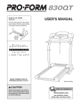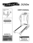
1
PRO.FORM
•l
Model No. 831.299281
Serial No.
83 o
'
USER'S MANUAL
Find the serial number in the location
shown below. Write the serial number
in the space above for reference.
Serial
Number
Decal
EXERCISE
EQUIPMENT
HELPLINE!
1-800-736-6879
SEARS, ROEBUCK AND CO.
HOFFMAN ESTATES, IL 60179
Patent Pending
www.proform.com
new products, prizes,
fitness tips, and much more!
PRO.FORM'83OQT
III
i'rr'l'lr"
,,,
TABLE OF CONTENTS
IMPORTANT PRECAUTIONS .................................................................
BEFORE YOU BEGIN .......................................................................
ASSEMBLY ...............................................................................
OPERATION AND ADJUSTMENT
.............................................................
HOWTO FOLD AND MOVE THE TREADMILL
..................................................
TROUBLE-SHOOTING
.....................................................................
CONDITIONING GUIDELINES ...............................................................
PART LIST ...............................................................................
ORDERING REPLACEMENT PARTS ..................................................
FULL 90-DAY WARRANTY ...........................................................
Note: An EXPLODED
2
DRAWING is attached in the center of this manual.
3
5
6
8
19
20
22
23
Back Cover
Back Cover
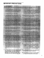
IMPORTANT PRECAUTIONS
o!
OI1
cord;
treadmill.
i;i9
is UL 1449 listed as a transi
suppressor (TVSS). The surge suppressor
must have a UL sUppresSed voitage rating of
400 Volts or less and a minimum surge dissi- .
¢line of the treadmill by
the treadmill,
20. When folding or mov ng the treadmill make
sure tl_at the storage latch is fully closed.
3
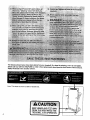
The decals shown below have been placed on your treadmill. If a decal is missing, or if it is not legible,
please call our toll-free HELPLfNE to order a free replacement decal (see the front cover of this manual).
Apply the decal in the location shown.
Note: This decal is shown at 38% of actual size.
4
KEEP HANDSAND FEETAWAY
FROM THIS AREAWHILE THE
TREADMILL IS IN OPERATION.
BEFORE YOU BEGIN
Thank you for selecting the revolutionary PROFORM •
830QT treadmill. The 830QT treadmill combines advanced technology with innovative design to help you
get the most from your exercise program in the convenience and privacy of your home. And when you're not
exercising, the unique 830QT can be folded up, requiring less than half the floor space of other treadmills.
Monday through Saturday, 7 a.m. until 7 p.m. Central
Time (excluding holidays). To help us assist you,
please note the product model number and serial number before calling. The model number of the treadmill
is 831.299281. The serial number can be found on a
decal attached to the treadmill (see the front cover of
this manual for the location).
For your benefit, read this manual carefully before
using the treadmill. If you have additional questions,
please call our toll-free HELPLINE at 1-800-736-6879,
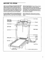
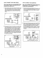
Before reading further, please review the drawing
below and familiarize yourself with the parts that are
labeled.
Book Holder
Water Bottle
Holder (Bottle
not included)
Console
Pulse Sensol
Handrail
LEFT SIDE
RIGHT SIDE
Lock Knob
On/Off Switch
Circuit
Breaker
Walking Belt
Front
Wheel
Foot
Powe
Rear Roller
Adjustment Bolts
--
.3ord
Cushioned Walking Platform
5
ASSEMBLY
Assembly requires two people. Set the treadmill in a cleared area and remove all packing materials. Do not
dispose of the packing materials until assembly is completed. Assembly requires the included allen wrenc_J
and your own phillips screwdriver (IZ_
=====" •
Note: The underside of the treadmill walking belt is coated with high-performance lubricant. During shipping, a
small amount of lubricant may be transferred to the top of the walking belt or the shipping carton. This is a normal
condition and does not affect treadmill performance. If there is lubricant on top of the walking belt, simply wipe off
the lubricant with a soft cloth and a mild, non-abrasive cleaner.
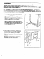
1,
With the help of a second person, carefully raise the
treadmill to the upright position.
While a second person tips the treadmill to one side and
holds it, insert one of the Extension Legs (103) into the
treadmill as shown. Make sure that the Extension Leg is
turned so the Base Pad (97) is on the bottom.
Next, tip the treadmill to the other side and insert the
other Extension Leg (not shown) in the same way. Lower
the side of the treadmill so that both Extension Legs
(103) are resting flat on the floor.
97
2. With the help of a second person, carefully tip the
Uprights (82) down as shown. Make sure that the
Extension Legs (103) remain in the Uprights.
Attach each Extension Leg (103) with two Screws (76)
as shown.
With the help of a second person, carefully tip the.
Uprights (82) back to the vertical position.
3. Locate the plastic tie in the post on the left Upright (82).
Hold a Handrail Extension (85) in the position shown.
Insert the plastic tie into the Handrail Extension as you
insert the Handrail Extension into the post. Attach the
Handrail Extension with three Screws (76). The plastic tie
is tied to the Pulse Wire (124). Be careful to avoid
damaging the Pulse Wire. The Pulse Wire is used with
the optional chest pulse sensor (see page 18).
3
"
124 76_.it
Slide a Handrail Foam Grip (110) onto the Handrail
Extension (85). Press two Plastic Fasteners (47) into the
Handrail Foam Grip.
Attach the other Handrail Extension and Handrail Foam
Grip to the right Upright (not shown). Note: There is not a
pulse wire in the right Upright.
4. Make sure that the Lock Knob Sleeve (111) is fully inserted into the left Upright (82).
4
Remove the Lock Knob (102) from the Lock Pin (115).
Make sure that the Lock Pin Collar (113) and the Spring
(112) are on the Lock Pin. Insert the Lock Pin into the left
Upright (82) and tighten the Lock Knob onto it.
102
5. Make sure that all parts are tightened before you use the treadmill. Keep the included allen wrench in a
secure place. The allen wrench is used to adjust the walking belt (see page 21). To protect the floor or carpet
from damage, place a mat under the treadmill.
7
CALS/FAT CALS!
PULSE display--This
display shows the approximate numbers of
calories and fat calories
_E1(6 r_LEE
[]
Stand on the
foot rails and
122
""
_
r_T
on the pulse bar.
Your palms
must be resting
on the upper
EKG PULSE
contacts, and
your fingers must
be touching the
lower contacts-CALORIES
FAT CALORIES
avoid moving
your hands.
When your pulse
is detected, the heart-shaped indicator in the
CALS/FAT CALS/PULSE display will flash
steadily and a series of dashes (----)
will appear. After a few seconds, your heart rate will be
shown. For the most accurate heart rata reading, continue to hold the contacts for about 15
seconds.
SPEED/MIN-MILE
- 122
display--This display
shows the speed of the
walking belt and your
current pace (pace is
measured in minutes per
mile). Every seven seconds, the display will
change from one number to the other, as shown
by the arrows in the display.
change the unit of meaS#EEO MIN/MILE(P4n)
surement. When the desired unit of measurement is selected, remove and then reinsert the
key. Note: For simplicity, all instructions in this
manual refer to miles.
Note: To reset the displays, press the STOP button, remove the key, and then reinsert the key.
Sensors
place your
hands on the
metal contacts
you have burned (see
FAT BURNING on page 22). Every seven seconds, the display will change from one number to
the other, as shown by the arrows in the display.
This display will also show your heart rate when
the pulse sensor is used (see step 6 on this page).
Note: The SPEED/MIN-MILE display can show
speed in either miles per hour or Idlometers per
hour. To determine which unit of measurement is
selected, hold down the STOP button while inserting the key into the console. An "E," for english
miles, or an =M," for metric kilometers, will appear
in the display. Press the
SPEED A button to
_"
Measure your pulse, if desired.
B
When you are finished exercising, remove the
key.
Step onto the foot rails,
press the STOP button,
and remove the key from
the console. Keep the
key in a secure place.
Note: If the displays
and various indicators on the console remain
lit after the key is removed, the console is in
the "demo" mode. Refer to page 18 and turn off
the demo mode.
When you are finished using the treadmill, move
the on/off switch near the power cord to the off
position.
11
_,
B
One speed setting and one incline setting are programmed for each segment. When only three seconds remain in the first s_gment, a series of tones
will sound and the treadmill will automatically adjust to the speed and incline settings for the second
segment.
_:_,:_.
_:,, _..................
:_! .........
Insert the key into the console,
When the key is insealed, the four displays
and various indicators
on the console will light.
The program will continue in this way until the
TIME/INCLINE/SEG TIME display counts down to
zero. The walking belt will then slow to a stop.
If the speed or incline setting for the current segment is too high or too tow, you can manually
override the settings by pressing the SPEED or
INCLINE buttons on the console. However, when
the next segment begins, the treadmill will adjust to the next speed and incline settings of
the program.
_'_ Se|ect one of the personal trainer programs.
When the
key is inserted, the
manual
mode will be
selected and
the MANUAL
indicator will
light. To select one of
the personal
trainer programs, press the PROGRAM button repeatedly until one of the six personal trainer program indicators lights.
The console features two tow intensity programs,
two medium intensity programs, and two high intensity programs. The profiles on the console
show how the speed and incline of the treadmill
will change during the programs. The numbers
beside the profiles show the maximum speed and
incline settings for the programs. For example, the
upper left profile shows that the treadmill will
reach a maximum speed of 4.5 mph and a maximum incline of 5% during the first program.
_1
Press the START button or the SPEED z_button
to start the program.
A moment after the button is pressed, the treadmill will automatically adjust to the first speed and
incline settings for the program, Hold the handrails
and begin walking.
Each program is divided
into several time
segments of different
lengths. The TIME/
INCLINE/SEG TIME
display shows both the
time remaining in the program and the time
remaining in the current segment of the program.
12
To stop the program, press the STOP button. The
TIME/INCLINE/SEG TIME display will begin to
flash. To restart the program, press the START
button or the SPEED A button. To end the program, press the STOP button, remove the key,
and then reinsert the key.
L_l Follow your progress with the LED track and
the four displays.
Refer to step 5 on page 10.
r_
Measure your pulse, if desired.
See step 6 on page 11.
_When
the program is completed, remove the
key from the console.
When the program has
ended, remove the key
from the console. Keep
the key in a safe place.
Note: If the displays
and indicators on the
console remain lit after the key is removed, the
console is in the "demo" mode. Refer to page
18 and turn off the dame mode.
When you are finished using the treadmill, move
the on/off switch near the power cord to the off
position.
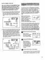
HOW TO CONNECT YOUR PORTABLE STEREO
To use iFit.com CD's, the treadmill must be connected to your portable CD player, portable stereo,
home stereo, or computer with CD player. See pages
13 and 14 for connecting instructions. To use iFit.com
videocassettes, the treadmill must be connected to
your VCR. See page 15 for connecting instructions.To
use iFit.com programs directly from our internet
site, the treadmill must be connected to your home
computer. See page 14 for connecting instructions.
Note: If your stereo has an RCA-type AUDIO OUT
jack, see instruction A below. If your stereo has a
3.5mm LiNE OUT jack, see instruction B. If your
stereo has only a PHONES jack, see instruction C.
A. Plug one end of the audio cable into the jack on the
front of the treadmill near the power cord. Plug the
other end of the cable into the included adapter. Plug
the adapter into an AUDIO OUT jack on your stereo.
A
HOW TO CONNECT YOUR PORTABLE CD PLAYER
Note: If your CD player has separate LINE OUT and
PHONES jacks, see instruction A below, if your CD
player has only one jack, see instruction B.
A. Plug one end of the audio cable into the jack on the
front of the treadmill near the power cord. Plug the
other end of the cable into the LINE OUT jack on
your CD player. Plug your headphones into the
PHONES jack.
A
II
Au,
o
.
i,-_
-,.-1
Cable
..................
I'_"CO'_)i
i - _
i
Audio
Cable
Adapter_
B. Plug one end of the audio cable into the jack on the
front of the treadmill near the power cord. Plug the
other end of the cable into the LINE OUT jack on
your stereo.
B
,........
::=
phones
j
[]
B. Plug one end of the audio cable into the jack on the
front of the treadmill near the power cord. Plug the
other end of the cable into a 3.5ram Y-adapter
(available at electronics stores). Plug the Y-adapter
into the PHONES jack on your CD player. Plug your
headphones into the other side of the Y-adapter.
B
Audio
i_ _
i
Cable
i--,,-Z_z-_--_--.___
J_ _
C. Plug one end of the audio cable into the jack on the
front of the treadmill near the power cord. Plug the
other end of the cable into a 3.5mm Y-adapter
(available at electronics stores). Plug the Y-adapter
into the PHONES jack on your stereo. Plug your
headphones into the other side of the Y-adapter.
C
i
..................:
[]
_i
_
3.5mm
Audio
Cable
,_
Y-adapter_
.................
i:[] _
.
_
_,
Audio
! @_
L,aele
::
3.Smm
Y-adapterJ
Headphones
|
13
HOW TO CONNECT YOUR HOME STEREO
HOW TO CONNECT YOUR COMPUTER
Note: If your stereo has an unused LINE OUT jack,
see instruction A below. If the LINE OUT jack is
being used, see instruction B.
Note: If your computer has'a3.Smm LiNE OUT jack,
see instruction A. If your computer has only a
PHONES jack, see instruction B.
A. Plug one end of the audio cable into the jack on the
front of the treadmill near the power cord. Plug the
other end of the cable into the included adapter.
Plug the adapter into the LINE OUT jack on your
stereo.
A. Plug one end of the audio cable into the jack on the
front of the treadmill near the power cord. Plug the
other end of the cable into the LINE OUT jack on
your computer.
IA
A
-.._.*.r
....
i
i_
LI
i'_"_'_i
i @_
Audio
i
"-"
i
Cable
_'
Adapter_
Cable
"_
B. Plug one end of the audio cable into the jack on the
front of the treadmill near the power cord. Plug the
other end of the cable into the included adapter.
Plug the adapter into an RCA adapter (available at
electronics stores). Next, remove the wire that is
currently plugged into the LINE OUT jack on your
stereo and plug the wire into the unused side of the
RCA adapter. Plug the RCA adapter into the LINE
OUT jack on your stereo.
B. Plug one end of the audio cable into the jack on the
front of the treadmill near the power cord. Plug the
other end of the cable into a 3.5mm Y-adapter
(available at electronics stores). Plug the Y-adapter
into the PHONES jack on your computer. Plug your
headphones or speakers into the other side of the
Y-adapter.
B
B
;_"1 (_i
i @ I-_i
;......
:**.J .............
r .........
Audio
---- 3.5mm
uable
= Y-adapteT-"
.,'
Headph ones/Speakers --_,.c3::_
Ir
.
i_--_
Audio
,@_
Cable
'-- -.,=E3m,._
RCA
AdapteTAdapter
Wire removed from -_,--[_,,_
LINE OUT jack
14
HOW TO CONNECT YOUR VCR
Note: If your VCR has an unused AUDIO OUT jack,
see instruction A below, if the AUDIO OUT jack is
being used, see instruction B. If you have a TV
with a built-in VCR, see instruction B. If your VCR
is connected to your home stereo, see HOW TO
CONNECT YOUR HOME STEREO on page 14.
A. Plug one end of the audio cable into the jack on the
front of the treadmill near the power cord. Plug the
other end of the cable into the included adapter.
Plug the adapter into the AUDIO OUT jack on your
VCR.
To use iFit.com CD's or videocassettes, the treadmill
must be connected to your portable CD player, portable
stereo, home stereo, computer with CD player, or
VCR. See HOW TO CONNECT THE COMPUTER TO
YOUR CD PLAYER, VCR, OR COMPUTER on page
13. Note: To purchase iFit.com CD's or to purchase
iFit.com videocassettes, call toll-free 1-800-7350768.
Make sure that the on/off
switch near the power cord
is in the on position. In
Position
addition, make sure that the
power cord is properly
plugged in (see HOW TO
PLUG IN THE POWER CORD on page 8).
A
I[
v
i'__i
i_
i
Audio
Cable
Adapter_
T
B. Plug one end of the audio cable into the jack on the
front of the treadmill near the power cord. Plug the
other end of the cable into the included adapter.
Plug the adapter into an RCA adapter (available at
electronics stores). Next, remove the wire that is
currently plugged into the AUDIO OUT jack on your
VCR and plug the wire into the unused side of the
RCA adapter. Plug the RCA adapter into the AUDIO
OUT jack on your VCR.
B
I[
I
When you are ready to begin exercising, step onto the
foot rails of the treadmill. Find the clip attached to the
key (see the drawing on page 9), and slide the clip
onto the waistband of your clothing. Follow the steps
below to use an iFit.com CD or video. Note: The instructions included in the CD case describe how to
use the CD with a variety of PROFORM treadmills.
Some instructions may not apply to this treadmill.
B
When the key is
inserted, the four displays
and various indicators
on the console will light.
B
v
;..........:_"!
i['__0)
_-_
Audio
Cable
Insert the key fully into the console.
Press the PROGRAM button.
When the key is inserted, the manual
mode will be selected.
To use an iFit.com CD
L
RCA Adapter--_]
i
Adapter
l
or video program, press
the PROGRAM button.
The iFit.com indicator
will light.
Wire removed from_
AUDIO OUT jack
_1
Insert the iFit.com CD or videocassette.
if you are using an iFit.com CD, insert the CD into
your CD player. If you are using an iFit.€om videocassette, insert the videocassette into your VCR.
15
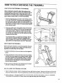
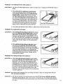
HOW TO FOLD AND MOVE THE TREADMILL
HOW TO FOLD THE TREADMILL
FOR STORAGE
Before folding the treadmill, adjust the incline to the
lowest position. If this is not done, the treadmill may be
permanently damaged. Next, unplug the power cord.
CAUTION: You must be able to safely lift 45 pounds (20
kg) in order to raise, lower, or move the treadmill.
1. Hold the treadmill with your hands in the locations shown
at the right. CAUTION: To decrease the possibility of injury, bend your legs and keep your back straight. As
you raise the treadmill, make sure to lift with your legs
rather than your back. Raise the treadmill about halfway
to the vertical position.
2. Move your right hand to the position shown and hold the
treadmill firmly. Using your left hand, pull the latch knob
to the left and hold it. Raise the treadmill until the latch
2
Open
pin is aligned with the hole in the catch. Insert the latch
pin into the catch. Make sure that the latch pin Is fully
inserted into the catch.
Closed
To protect the floor or carpet from damage, place a
mat under the treadmill. Keep the treadmill out of
direct sunlight. Do not leave the treadmill in the storage position in temperatures above 85 ° Fahrenheit.
HOW TO MOVE THE TREADMILL
Before moving the treadmill, convert the treadmill to the storage position as described above. Make sure that the storage latch is closed fully over the catch.
1. Hold the handrails as shown and place one foot against a
wheel.
2. Tilt the treadmill back until it rolls freely on the front wheels.
Carefully move the treadmill to the desired location. Never
move the treadmill without tipping it back. To reduce
the risk of injury, use extreme caution while moving
the treadmill. Do not attempt to move the treadmill
over an uneven surface.
3. Place one foot on the base, and carefully lower the treadmill until it is resting in the storage position.
HOW TO LOWER THE TREADMILL
ase
:ront Wheels
FOR USE
1. Refer to drawing 2 above. Hold the treadmill with your right hand as shown. Using your left hand, pull the latch
knob to the left and hold it. Pivot the treadmill down until the frame is past the pin. Slowly release the latch knob.
2. Refer to drawing 1. Hold the treadmill firmly with both hands, and lower the treadmill to the floor. CAUTION:
To decrease the possibility of injury, bend your legs and keep your back straight.
19
TROUBLE-SHOOTING
Most treadmill problems can be solved by following the simple steps below. Find the symptom that
applies, and follow the steps listed. If further assistance is needed, call our toll-free HELPLINE at
1-800-736-6879, Monday through Saturday, 7 a.m. until 7 p.m. Central Time (excluding holidays).
PROBLEM:
The power does not turn on
SOLUTION:
a. Make sure that the power cord is plugged into a surge suppressor, and that the surge suppressor
• is plugged into a propedy grounded outlet (see page 7). Use only a single-outlet surge suppressor
that is UL 1449 listed as a transient voltage surge suppressor (TVSS). The surge suppressor
must have a UL suppressed voltage rating of 400 volts or less and a minimum surge dissipation
of 450 joules. The surge suppressor must be electrically rated for 120 volts AC and 15 amps.
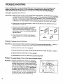
b. After the power cord has been plugged in, make sure that the key is fully inserted into the console. See step 1 on page 10.
c. Check the circuit breaker located on the treadmill
near the power cord. If the sw(tch protrudes as
shown, the circuit breaker has tripped. To reset the
circuit breaker, wait for five minutes and then press
the switch beck in.
d. Check the orv'off switch located on the traadmiil
near the power cord. The switch must be in the on
position.
C
Tdpped
Id
Reset
OnJ
Position
PROBLEM:
The power turns off during use
SOLUTION:
a. Check the circuit breaker located on the treadmill frame near the power cord (see 1. c. above). If
the circuit breaker has tripped, wait for five minutes and then press the switch back in.
b. Make sure that the power cord is plugged in.
c. Remove the key from the console. Reinsert the key fully into the console. See step 1 on page 10.
d. Make sure that the on/off switch is in ihe on position.
e, If the treadmill still will not run, please call our toll-free HELPLINE.
2O
PROBLEM:
The speed display on the console does not function properly
SOLUTION:
a. Remove the key from the console and unplug the
power cord. Remove the screws from the hood and
carefully remove the hood. Locate the Reed Switch
(21) and the Magnet (43) on the left side of the Pulley
(42). Turn the Pulley until the Magnet is aligned with
the Reed Switch. Make sure that the gap between
the Magnet and the Reed Switch is about 1/8". tf
necessary, loosen the Reed Switch Screw (76) and
move the Reed Sw(tch slightly. Retighten the Screw.
Re-attach the hood, and run the treadmill for a few
minutes to check for a correct speed reading.
PROBLEM:
The walking belt slows when walked on
SOLUTION:
a. Use only a UL-listed surge protector, rated at 15 amps, with a 14-gauge cord of five feet or less in
length.
b.
If the walking belt is ovedightened, treadmill performance may decrease and the walking belt may become damaged. Remove the key and UNPLUG THE
POWER CORD. Using the allen wrench, turn both
rear roller adjustment bolts counterclockwise, 114 of a
turn. When the walking belt is properly tightened, you
should be able to lift each side of the walking belt 3 to
4 inches off the walking platform. Be careful to keep
the walking belt centered. Plug in the power cord, inserf the key and run the treadmill for a few minutes.
Repeat until the walking belt is properly tightened.
b
Rear Roller Adjustment Bolts
c. If the walking belt still slows when walked on, please call our toll-free HELPLINE.
PROBLEM: The walking belt is off-center
SOLUTION:
a. If the walking belt has shifted to the left, first remove
the key and UNPLUG THE POWER CORD. Using the
allen wrench, turn the left rear roller adjustment bolt
clockwise, and the right bolt counterclockwise, 114 of a
turn each. Be careful not to overtighten the walking belt.
Plug in the power cord, insert the key and run the treadmill for a few minutes. Repeat until the walking belt is
centered.
a
b. If the walking belt has shifted to the right, first remove the key and UNPLUG THE POWER CORD.
Using the allen wrench, turn the left roar roller adjustment bolt counterclockwise, and the right bolt clockwise,
1/4 of a turn each. Be careful not to overtighten the
walking belt. Plug in the power cord, insert the key and
run the treadmill for a few minutes. Repeat until the
walking belt is centered.
PROBLEM: The walking belt slips when walked on
SOLUTION:
a. If the walking belt slips when walked on, first remove
the key and UNPLUG THE POWER CORD. Using the
allen wrench, turn both rear roller adjustment bolts
clockwise, 1/4 of a turn. When the walking belt is correctly tightened, you should be able to lift each side of
the walking belt 3 to 4 inches off the walking platform.
Be careful to keep the walking belt centered. Plug in the
power cord, insert the key and carefully walk on the
treadmill for a few minutes. Repeat until the walking belt
is properly tightened.
a
PROBLEM:
The incline of the treadmill does not change correctly or does not change when i-Fit.com
CD's and videos are played
SOLUTION:
a. With the key inserted in the console, press one of the INCLINE buttons. While the incline is
changing, remove the key. After a few seconds, re-insert the key. The treadmill will automatically rise to the maximum incline level and then return to the minimum level. This will recalibrate
the incline.
21
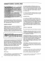
CONDITIONING
GUIDELINES
uses easily accessible carbohydrate calories for energy. Only after the first few minutes does your body
begin to use stored fat calories for energy. If your goal
is to burn fat, adjust the speed and incline of the treadmill until your heart rate is near the lowest number in
your training zone.
For maximum fat burning, adjust the speed and incline
of the treadmill until your heart rate is near the middle
number in your training zone.
Aerobic Exercise
The following guidelines will help you to plan your exercise program. Remember--these
are general guidelines only, For more detailed exorcise information, obtain a reputable book or consult your physician.
EXERCISE
INTENSITY
Whether your goal is to bum fat or to strengthen your
cardiovascular system, the key to achieving the
desired results is to exercise with the proper intensity.
The proper intensity level can be found by using your
heart rate as a guide. The chart below shows recommended heart rates for fat burning and aerobic exercise.
HEART
RATE TRAINING
_,=,,20
ZONES
30
40
sO
60
70
8o
To find the proper heart rate for you, first find your age
near the bottom of the chart (ages are rounded off to
the nearest ten years). Next, find the three numbers
above your age. The three numbers define your "training zone." The lower two numbers are recommended
heart rates for fat burning; the higher number is the
recommended heart rate for aerobic exercise.
To measure your heart rate during exercise, use the
pulse sensor on the console. If your heart rate is too
high or too low, adjust the speed and incline of the
treadmill.
Fat Burning
To burn fat effectively, you must exercise at a relatively
low intensity level4or a sustained period of time.
During the first few minutes of exercise, your body
22
If ycur goal is to strengthen your cardiovascular system, your exercise must be "aerobic." Aerobic exercise
is activity that requires large amounts of oxygen for
prolonged periods of time. This increases the demand
on the heart to pump blood to the muscles, and on the
lungs to oxygenate the blood. For aerobic exercise,
adjust the speed and incline of the treadmill until your
heart rate is near the highest number in your training
zone.
WORKOUT
GUIDELINES
Each workout should include the following three parts:
A Warm-up_-Start each workout with 5 to 10 minutes
of stretching and light exercise. A proper warm-up increases your body temperature, heart rate and circulation in preparation for exercise.
Training Zone Exercise---After warming up, increase
the intensity of your exemise until your pulse is in your
training zone for 20 to 60 minutes. (Dudng the first few
weeks of your exercise program, do not keep your
pulse in your training zone for longer than 20 minutes.)
Breathe regularly and deeply as you exercise--never
hold your breath.
A Cool-down--Finish each workout with 5 to 10 minutes of stretching to cool down. This will increase the
flexibility of your muscles and will help prevent post-exercise problems.
Exercise Frequency
To maintain or improve your condition, complete three
wcrkouts each week, with at least one day of rest between workouts. After a few months, you may complete up to five workouts each week if desired.
The key to success is to make exercise a regular and
enjoyable part of your everyday life.
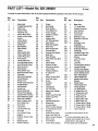
PART LISTmModel No. 831.299281
R1199A'
To locate the parts listed below, refer to the EXPLODED DRAWING attached in the center of this manual.
Key
No.
Qty.
Description
Key
No.
Qty.
Description
1
2
3
1
1
4
Motor Belt
Pulley/Flywheel/Fan
Motor Nut
48
49
50
1
2
1
Shield
Belt Guide
Book Holder
4*
1
5
6
1
1
Motor/Pulley/
Flywheel/Fan
Incline Motor Bolt
Plastic Incline Motor
51
52
53
54
1
1
4
4
Front Belly Pan
Power Supply
Cable Tie Clamp
Cable Tie
7
8
9
10
11
12
13
14
15
16
17
18
19
20
21
1
1
1
2
1
1
1
1
8
4
4
2
1
2
1
Spacer
Incline Motor
Stop Bracket
Small Nut
Star Washer
Optic Switch
Frame
Optic Switch Bolt
Incline Optic Disk
Incline Motor Nut
Hood Screw
Plastic Stand-Off
Hood Bracket (shod)
Hood Bracket (long)
Warning Decal
Reed Switch
55
56
57
58
59
60
61
62
63
64
65
66
67
68
69
70
1
1
1
1
2
1
1
5
1
1
2
1
1
4
6
1
Walking Belt
20" Wire Harness
Rear Roller
Belly Pan Spacer
Rear Foot
Rear Foot Screw
Ground Wire
Ground Wire Screw
Belly Pan
Rear Endcap
Rear Roller Adj. Bolt
Motor
Latch Decal
Platform Screw
Electronics Screw
Latch Catch
22
23
24
25
26
27
28
29
30
31
32
33
34
35
36
37
1
1
1
1
1
1
1
1
1
1
2
2
1
1
3
2
71
72
73
74
75
76
77
78
79
80
81
82
83
84
1
5
1
1
2
18
1
1
4
1
4
1
2
2
38
39
40
41
42
43
44
45
46
47
4
2
1
2
1
1
2
2
4
15
Reed Switch Clip
Motor/Controller Wire
Controller
Electronics Bracket
Circuit Breaker
Power Cord
Power Cord Grommet
On/Off Switch
Inlet Bracket
Incline Leg
Frame Pivot Bolt
Frame Pivot Spacer
Upright Wire Harness
Front Roller Adj. Bolt
Roller Adj. Washer
Motor Tension NuV
Front Roller Nut
Motor Bolt
Cap Screw
Left Foot Rail Cap
Foot Rail
Front RolledPulley
Magnet
Platform Screw (mid)
Isolator
Isolator Screw
Plastic Fastener
85
86
87
88
89
90
91
92
93
94
95
96
2
2
1
1
10
1
1
1
1
1
2
1
Walking Platform
8" Cable Tie
Jack
Motor Tension Bolt
Foot Rail Insert
Screw
Console
Choke
Long Screw
10' I-Fit Wire
Motor Star Washer
Updght
Incline Leg Pivot Bolt
Incline Leg Pivot
Washer
Handrail Extension
Wheel Bolt
Console Base
Motor Tension Washer
Console/Catch Screw
Key/Clip
Incline Motor Plate
Right Foot Rail Cap
Motor Tension Spacer
Motor Hood
Front Wheel
Incline Motor Shield
Key
No.
Qty,
97
98
99
100
101
102
4
1
1
1
11
1
Base Pad
12" Audio Wire
Upright Grommet
Allen Wrench
Short Screw
Lock Knob
103
104
105
2
2
1
Extension Leg
Extension Leg Cap
Shock
106"*
2
107
108
109
2
2
1
Extension Leg
Assembly
Pulse Bar Bolt
Pulse Bar Washer
Pulse Bar
110
111
112
113
114
115
116
117
118"*
119
2
1
1
1
1
1
1
2
1
8
120
121"*
122
1
1
1
123
124
125
#
#
#
#
#
#
#
#
#
#
#
2
1
1
1
1
1
1
1
1
1
1
1
1
1
Description
Handrail Foam Grip
Lock Knob Sleeve
Spring
Lock Pin Collar
Pin Clip
Lock Pin
Console Base Bottom
Upright Endcap
Chest Pulse Sensor
Hood Bracket Screw/
Incline Shield Screw
Rear Foot Spacer
Hand Weight Set
Metal Incline Motor
Spacer
Static Decal
Hand Pulse Wire
Choke Bracket
10" White Wire
8" White Wire, 2F
4" White Wire, M/F
8" Blue Wire, 2F
4" Blue Wire, 2F
4" Black Wire, M/F
4" Black Wire, 2F
4" Green Wire, FIRing
8" Green Wire, F/Ring
8" Green Wire, 2 Ring
User's Manual
* Includes all parts shown in the
box
**For more information about the
optional hand weight set or chest
pulse sensor, see page 18
# These parts are not illustrated
23
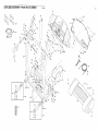
EXPLODED
DRAWING--Model
37
No. 831,299281
R1199A ''_'_ L-'"
9
6
I
119
74
69
i
33
41
,
15
32
75
4.
71
45
51
"_°L101
7O
55
100
01
57
46
47
6O
_36
63
65
2O
SAVE THE EXPLODED DRAWING
FOR FUTURE REFERENCE.
67
65
6O
36
To identify the parts shown on this exploded drawing, refer to the
PART LIST on page 23 of the USER'S MANUAL.
EXPLODED
DRAWING--Model
No. 831.299281
m199A
h_
87
117
9O
5O
79
77
117
24
85
\
109
102
110
112
113
115
111
i i
82
\
110
114
84
83
47
86
47
91
20
i
,
73
16
15
._123
16
86
105_........-'"'"""
20
101
104 __1_i_'_
_106"
94
16
SEARS
The model number and serial number of your PROFORM" 830QT
treadmill are listed on a decal attached to the frame. See the front
cover of this manual to find the location of the decal.
Model No. 831.299281
A{I replacement parts are available for immediate purchase or
special order when you .visit your nearest SEARS Service Center..
To request service or to order parts by telephone, call the toll-free
numbers listed at the left.
QUESTIONS?
If you find that:
• you need help assembling or
operating the PROFORM
830QT treadmill
When requesting help or service, or ordering parts, please be
prepared to provide the following information:
• a part is missing
• The NAME OF THE PRODUCT (PROFORM ®830QT treadmill)
• or you need to schedule repair
service
• The MODEL NUMBER OF THE PRODUCT (831.299281)
call our toll-free HELPLINE
1-800-736-6879
Monday-Saturday,
7 am-7 pm
Central Time (excluding holidays)
• The KEY NUMBER AND DESCRIPTION OFTHE PART (see the
EXPLODED DRAWING in the center of this manua_ and the
PART LIST on page 23).
REPLACEMENT
PARTS
If parts become worn and need
to be replaced, call the following
toll-free number
1-800-FON-PART
(1-800-366-7278)
FULl 90 DAY WARRANTY
For 90 days from the date of purchase, if failure occurs due to defect in matedal or workmanship in this
SEARS TREADMILL EXERCISER, contact the nearest SEARS Service Center throughout the United
States and SEARS will repair or replace the TREADMILL EXERCISER, free of charge.
This warranty does not apply when the TREADMILL
poses.
EXERCISER is used commercially or for rental pur-
This warranty gives you specific legal rights, and you may also have other rights which vary from state
to state.
SEARS, ROEBUCK AND CO., DEPT. 817WA, HOFFMAN
Part No. 161697 R1199A
ESTATES, IL 60179
Printed in USA © 1999 Sears, Roebuck and Co.