1
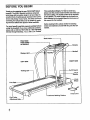
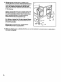
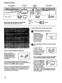
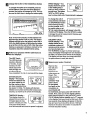
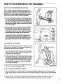
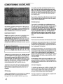
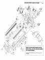
Model No. 831.298400
Serial No.
Find the serial number"in the location
shown below. Write the serial number
in the space above for reference.
HELPLINE!
1-800-736-6879
USER'S MANUAL
SEARS, ROEBUCK AND CO., HOFFMAN
ESTATES,
IL 60179
TABLE OFCONTENTS
IMPORTANT PRECAUTIONS ................................................................
BEFORE YOU BEGIN .......................................................................
ASSEMBLY ...............................................................................
OPERATION AND ADJUSTMENT
.............................................................
HOW TO FOLD AND MOVE THE TREADMILL ..................................................
MAINTENANCE AND TROUBLE-SHOOTING
.......
. ...........................................
CONDITIONING GUIDELINES
...............................................................
PART LIST ...............................................................................
ORDERING REPLACEMENT PARTS ..................................................
FULL 90-DAY WARRANTY ...........................................................
Note: An EXPLODED
IMPORTANT
2_.
DRAWING is attached in the center of this manual.
PRECAUTIONS
.2
4
5
7
11
12
14
15
Back Cover
Back Cover
The decals shown have been placed on
your treadmill. If a decal is missing, or
if it is not legible, please call our
Customer Service Department, toll-free,
to order a free replacement decal (see
ORDERING REPLACEMENT PARTS on
the back cover of this manual). Apply
the decal in the location shown.
• Never allow children on
or around ti'eadmill.
Storage latch must be
ed before
moved or
stored.
• Incline must be set at
lowest level before folding
treadmill into storage
position.
KEEP HANDSAND FEET AWAY
FROM THIS AREAWHILE THE
TREADMILLIS IN OPERATION.
3
BEFORE YOU BEGIN
Thank you for selecting the new PROFORM ° 535LE
treadmill. The 535LE treadmill combines advanced
technology with innovative design to let you enjoy an
excellent form of cardiovascular exercise in the convenience and privacy of your home. And when you're not
exercising, the unique 535LE _ be folded up, requiring less than half the floor space of other treadmills.
For your benefitt read this manuel carefully before
using the treadmill. If you have additional questions,
please call our toll-free HELPLINE at 1-800-736-6879,
Monday through Saturday, 7 a.m. until 7 p.m. Central
Time (exoluding holidays). To help us assist you,
please note the product model number and serial number before calling. The modal number of the treadmill
is 831.298400. The sedat number can be found on a
decal attached to the treadmill (see the front cover of
this manual for the location).
Before reading further, please review the drawing
below and fam.iliadze yourself with the parts that are
Irabeled.
Water Bottle
Holder (Bottle
no_ included)
Handrail
Storage Latch
LEFT SIDE
RIGHT SIDE
Walking
.Circu_
Breaker
Front
Wheel
F_tR_is
r Cord
Platform
r Roller
.-"
Adjustment Bolts
"
ASSEMBLY
_.ssembly requires two people. Set the treadmill in a cleared area and remove all packing materials. Do not
Jispose of the packing matedels until assembly is completed. Assembly requires the included allen wrenc_
and your own phillips screwdriver (]_m_ =-",=- .
1. With the help of a second person, carefully raise the
treadmill to the upright position. While a second person
tips the treadmill to one side and holds it, Insert one of
the Extension Legs (103) into the treadmill as shown.
Make sure that the Extension Leg is tumed so the Base
Pad (97) is on the bottom.
Next, tip the treadmill to the other side and insertthe
other Extension Leg (not shown) in the same way. Lower
the side of the treadmill so that both Extension Legs
(103) are resting flat on the floor.
2. Refer to HOW TO LOWER THE TREADMILL FOR USE
on page 11. Follow the instructions in step 2 to lower the
treadmill.
Attach the latch support to the canter hole in the left Upright
(82) with a 3/4" Screw (89). Make sure that the Screw is
tight, but do not overtighten it; if the Screw is overtightened, the latch will not slide smoothly.
82
Bracket_
Latch_
Remove the tape from the Latch Assembly (77). Be careful to hold the parts in place. Inset drawing (a) shows
how the Latch Assembly fits together. Refer to inset
drawing (b). Insert the springs into the bracket as shown.
Make sure the tabs are touching the bracket and the back
end of the latch is flush with the bracket.
Spring-Support
Flush.._.
b
Spdng--
Attach the Latch Assembly (77) to the left Upright (82)
with two 3/4" Screws (89).
3. Slide the upper end of a Handrail (85) into the right
Upright (82) as shown. Note: It will be necessary to
pivot the Handrail to the side and back repeatedly
(see arrow A) while pushing on the Handrail (see
arrow B) to slide it fully into the Upright. Next, pivot
the lower end of the Handrail down, push it toward the
right Upright, and then align it with the indicated hole.
a
2
_
Tab_
3
d
Slide the other Handrail (85) onto the left Upright (82) as
described above.
Attach the latch spacer and the latch support to the left
Upright (82) with a 3/4" Screw (81).
Hole
5
4: With the help of asecortd person, carefully tip the
Uprights (82) down as shown. Make sure the Extension
Legs (103) remain inserted into the Uprights. A_ach
one of the Extension Legs with two of the four Short
Screws (101) as shown. Attach the other Extension Leg
in the same way.
4
Tighten a Handrail Bolt (78) with a Handrail Washer (96)
into the right Extension Leg (103) and the lower end of
the right Handrail (85) as shown. Note: It may be necessary to move the Handrail up or down to align the
Handrail with the hole in the Extension Leg.
Next, tighten a Handrail Bolt (78) with a Handrail Washer
(96) into the left Extension Leg (103) and the lower end
of the left Handrail (85).
With the help of a second person, carefully tip the
• Uprights (82) back to the upright position.
82
101
'°
--lO 3 78
.__'-_l'-L / 98
lO3--.--_'-_,
8
5. Make sure that all parts are tightened before you use the treadmill. To protect the floor or carpet, place a
mat under the treadmill.
OPERATION
I
THE PERFORMANT
AND ADJUSTMENT
LUBE TM WALKING BELT
Your treadmill features a walking belt coated with
PERFORMANT LUBE TM, a high-performance lubricant.
IMPORTANT: Never apply silicone spray or other
substances to the walking belt or the walking platform. Such substances will deteriorate the walking
belt and cause excessive wear.
This product is for use on a nominal 120-volt circuit,
and has a grounding plug that looks like the plug lllustrated In drawing 1 below. A temporary adapter that
looks like the adapter illustrated in drawing 2 may be
used to connect the surge suppressor to a 2-pole
receptacle as shown in drawing 2 if a properly
grounded outlet is not available.
HOW TO PLUG IN THE POWER CORD
./iJr-_Grounded
_.
I
Outlet Box
_SurgeSupp
ressor
Greund,ngP,o
Grounded Outlet
2
Your treadmill, like any other type of sophisticated
electronic equipment, can be seriously damaged by
sudden voltage changes in your home's power.
/oltage surges, spikes, and noise interference can
result from weather conditions or from other appliances
being turned on or off. To decrease the possibility of
your treadmill being damaged, always use a surge
suppressor with your treadmill (see drawing 1 at
the right).
Surge suppressors are sold at most hardware stores
and department stores. Use only a single-outlet surge
suppressor that is UL 1449 listed as a transient voltage
surge suppressor (TVSS). The surge suppressor must
have a UL suppressed voltage rating of 400 volts or
less and a minimum surge dissipation of 450 joules.
The surge suppressor must be electrically rated for
120 volts AC and 15 amps.
This product must be grounded. If it should malfunction or break down, grounding provides a path of least
resistance for electric current to reduce the risk of electric shook. This product is equipped with a cord having
an equipment-grounding conductor and a grounding
plug. Plug the power cord into a surge suppressor,
and plug the surge suppressor into an appropriate
outlet that is properly installed and grounded in
accordance with all local codes and ordinances.
Grounding Plug"_
o0 e,
u;2o2O=
Box
___"
Surge Suppressor
Metal Screw
.
_,_
The temporary adapter should be used only until a
properly grounded outlet (drawing 1) can be installed
by a qualified electrician.
The green-colored rigid ear, lug, or the like extending
from the adapter must be connected to a permanent
ground such as a propedy grounded outlet box cover.
Whenever the adapter is used it must be held in place
by a metal screw. Some 2-pole receptacle outlet box
covers are not grounded. Contact a qualified electrician to determine if'the outlet box cover is
greund.ed before using an adapter.
7
CONSOLE DIAGRAM
,Pulse Sensor
I
Note: If there is a thin sheet of clear plastic
on the face of the console, remove iL
Follow the steps below to operate the console.
B
Insert the key fully into the console.
When the key is
inserted, one indicator
will light in the incline
display, one indicator
will light in the LED
track, and the four
displays will light.
B
I.--,/
F
_-"
t
"
Press the SPEED _ button to start the walking
belt.
A moment after the
SPEED Z_button is
STEP-BY-STEP
CONSOLE
Before operating the
console, make sure that
the on/off switch near
the power cord is in the
on position.
OPERATION
pressed, the walking belt
will begin to move. Hold
the handrails and carefully begin walking.
Position
Next, make sure that the key is removed from the
console and then plug in the power con:l (see HOW TO
PLUG IN THE POWER CORD on page 7).
When you are ready to begin exercising, step onto the
foot rails of the treadmill. Find the clip attached to the
key (see the drawing above), and slide the clip onto
the waistband of your clothing.
As you exercise, change the speed of the walking
belt as desired by pressing the SPEED buttons.
To stop the walking belt,
press the STOP/RESET
button. The TIME/PACE
display will begin to flash.
To restart the walking
belt, press the SPEED Z_
button again. To stop the walking belt and reset "
the displays press the STOP/RESET button for
about two seconds.
_"lChange
the incline Of the treadmill as desired.
SPEED display--This
display shows the speed
of the walking belt, In
miles per hour or kilomeSPEED
ters per hour. The letters
"MPH" dr'KPH" will appear to show which unit of measurement is selected.
-..
I " &B
1
To change the incline of the treadmill, press the
incline buttons. Each time one of the buttons is
pressed, the Incline will change by 0.5%. The buttons can be held down to change the incline rapidly.
To change the unit of
measurement, hold down
the STOP/RESET button
while inserting the key
DISTANCE
LAPS
into the console. An =E,"
for english miles, or an
"M," for metric kilometers, will appear in the DISTANCE/LAPS display. Press the SPEED Z_button
to change the unit of measurement.
then reinsert the key.
Note: In the incline display, the first indicator will
light when the incline is set at 1.5%. The second
indicator will light when the incline is set at 2% or
2.5%, the third indicator will light when the incline
is set at 3% or 3.5%, and so forth. After the incline
buttons are pressed, it will take a moment for the
treadmill to reach the selected incline setting.
B
CALS/FAT CALS/
PULSE display--This
display shows the approximate numbers of
calories and fat calories
you have burned (see
FAT BURNING on page 14). Every seven seconds, the display will change from one number to
the other, as shown by the arrows in the display.
This display will also show your heart rate when
the pulse sensor is used (see step 5).
Follow your progress with the LED track and
the four displays.
The LED Track-The LED track represents a distance
of 1/4 mile. As you
exercise, the indicators around the
j,/O09 0 0 0 0 0 O0_xL
\Oo O)
X ooooov
Remove and
B
Measure your pulse; if desired.
Stand on the
foot rails and
Pulse Sensor
track will light one
at a time until you
have completed 1/4 mile. A new lap will then begin.
place your
thumb on the
pulse sensor as
shown. The
DISTANCE/LAPS
pulse sensor is
pressureactivated--fully
press it down.
PULSE
!
Do not press
too hard, or the
CALS.
FAT CALS.
circulation in
your thumb will
be restricted, and your pulse will not be detected. Next, raise your thumb slightly until the'
•heart-shaped indicator in the CALSiFAT CALS/
PULSE display flashes steadily and a =P" appears
in the display. Hold your thumb at this level. After a
few seconds, three dashes will appear in the display and your heart rate will be shown. Hold your
thumb on the sensor for another 15 seconds for
the most accurate reading.
display--This display
shows the distance that
you have walked or run
DISTANCE
LAPS
and the number of laps
you have completed (one
lap equals 1/4 mile). The display will alternate
between one number and the other every seven
seconds, as shown by the arrows in the display.
TIME/PACE display-This display shows the
elapsed time and your current pace (pace is meaTIME
PACE
sured in minutes per mile).
Your pace will be shown
for a few seconds each time the speed is adjusted.
-7[; 122
9
Ifthedisplayedh_eart
rateappearsto betoo high
ortoo10w,orif yourheartrateis not displayed, lift
THE INFORMATION
your thumb off the sensor and allow the display to
reset. Press down again on the sensor as described above. Make sure that your thumb is positioned as shown, and that you are applying the
proper amount of pressure to the pulse sensor.
To access the informationreedS, hold down the STOP/
RESET button while inserting the key into the console.
Try the sensor several times until you become
familiar with iL Remember to stand still while measuring your pulse.
r_
When you are finished, remove the key.
S
e° °te
F t
and remove the key
from the console. Keep
the key in a secure
place.
In addition,movethe on/offswitchto the off position.(See the drawingnear the bottomof page 8.)
MODE
An "E," for english miles, or an
"M," for metric kilometers, will
appear in the DISTANCE/
LAPS display. Press the
SPEED Z_button to change
the unit of measurement.
The TIME/PACE display will
show the total number of
hours the treadmill has been
used.
IE
_
DISTANCE
1
LAPS_
Il ,, 11
TIME
PACE
The SPEED display will show
the total number of miles that
the walking belt has moved.
To exit the information mode, remove the key from the
console.
iO
HOW TO FOLD AND MOVETHE
HOW TO FOLD THE TREADMILL
TREADMILL
FOR STORAGE
Before folding the treadmill, adjust the incline to the
lowest position. If this is not done, the treadmill may be
permanently damaged. Next, unplug the power cord.
CAUTION: You must be able to safely lift 45 pounds (20
kg) in order to raise, lower, or move the treadmill.
1. Hold the treadmill with your hands in the locations shown
at the dght. CAUTION: To decrease the possibility of injury, bend your legs and keep your back straight. As
you raise the treadmill, make sure to lift with your legs
rather than your back. Raise the treadmill about halfway
to the vertical position.
2. Move your right hand to the position shown and hold the
treadmill firmly. Using your left thumb, slide the storage
latch to the left and hold it. Raise the treadmill until the
storage latch closes over the catch. Make sure that the
storage latch is fully closed over the latch catch.
To protect the floor or carpet from damage, place a
mat under the treadmill. Keep the treadmill out of
direct sunlight. Do not leave the treadmill in the storage position in temperatures above 85" Fahrenheit.
ROW TO MOVE THE TREADMILL
3
Before moving the treadmill, convert the treadmill to the storage position as described above. Make sure that the storage latch is closed fully over the catch.
,Book Holder
1. Hold the handrails as shown and place one foot against a
wheel. Do not hold or push on the book holder or the
book holder may be damaged.
2. Tilt the treadmill back until it mils freely on the front wheels.
Carefully move the treadmill to the desired location. Never
move the treadmill without tipping it back. To reduce
the risk of Injury, use extreme caution while moving
the treadmill. Do not attempt to move the treadmill
over an uneven surface.
3. Place one foot on the base, and carefullylower the treadmill until it is resting in the storage position.
HOW TO LOWER THE TREADMILL
- Front Wheels
FOR USE
1. Refer to drawing 2 above. Hold the upper end of the treadmill with your dght hand as shown. Using your left
thumb, slide the storage latch to the left and hold it. Pivot the treadmill down until the frame is past the storage
latch.
2. Refer to drawing 1 above. Hold the treadmill firmly with both hands, and lower the treadmill to the floor.
CAUTION: To decrease the possibility
of injury, bend your legs and keep your back straight.
11
TROUBLE-SHOOTING
Most treadmill problems can be solved by following the simple steps below. Find the symptom that
applies, and follow the steps listed. If further assistance is needed, call our toll-free HELPLINE at
1-800-736-6879, Monday through Saturday, 7 a.m. until 7 p.m. Central Time (excluding holidays).
PROBLEM:
The power does not turn on
SOLUTION:
a. Make sure that the power cord is plugged into a surge suppressor, and that the surge suppressor
is plugged into a properly grounded outlet (see page 7). Use only a single-outlet surge suppressor
that is UL 1449 listed as a transient voltage surge suppressor (TVSS). The surge suppressor
must have a UL suppressed voltage rating of 400 volts or less and a minimum surge dissipation
of 450 joules. The surge suppressor must be electrically rated for 120 volts AC and 15 amps.
b. After the power cord has been plugged in, make sure that the key is fully inserted into the console. See step 1 on page 8.
c. Check the circuit breaker located on the treadmill
near the power cord. If the switch protrudes as
shown, the circuit breaker has tripped. To reset the
cimuit breaker, wait for five minutes and then press
• the switch back in.
d. Check the on/off switch located on the treadmill
nearthe power cord. The switch must be in the On
position.
c
d
On
Position
PROBLEM:
The power turns off during use
SOLUTION:
a. Check the cimuit breaker located on the treadmill frame near the power cord (see 1. c. above). If
the circuit breaker has tripped, wait for five minutes and then press the switch back in.
b. Make sure that the power cord is plugged in.
c. Remove the key from the console. Reinsert the key fully into the console. See step 1 on page 8.
d. Make sure that the on/off switch is in the on position.
e. If the treadmill still will not run, please call our toll-frae HELPLINE.
PROBLEM:
The displays of the console do not function properly
SOLUTION:
a. Remove the key from the console and uplug the
power cord. Remove the screws from the hood.
Carefully remove the hood. Locate the Reed switch
(21) and the Magnet (43) on the left side of the Pulley
(42). Turn the Pulley until the Magnet is aligned with
the Reed Switch. Make sure that the gap between
the Magnet and the Reed Switch is about 118". If
necessary, loosen the Reed Switch Screw (76) and
move the Reed Switch slightly. Retighten the Screw.
Re-attach the hood, and run the treadmill for a few
minutes to check for a correct speed reading.
17.
I
PROBLEM:
The walking belt slows when walked on
SOLUTION:
a. Use only a UL-listed surge protector, rated at 15 stops, with a 14-gauge cord of five feet or less in
length.
b. If the walking belt is ovedightened, treadmill performance may decrease and the walking belt may be
permanently damaged. Remove the key and UNPLUG THE POWER CORD. Using the allen wrench,
turn both rear roller adjustment bolts counterclockwise, 114 of a turn. When the walking belt is properly
tightened, you should be able to lift each side of the
walking belt 3 to 4 inches off the walking platform. Be
careful to keep the walking belt centered. Plug in the
power cord, insert the key and run the treadmill for a
few minutes. Repeat until the walking belt is propedy
tightened.
c. If the walking belt still slows when walked on, please call our toll-free HELPLINE.
PROBLEM: The walking belt is off-center when walked on
SOLUTION:
a. If the walking belt has shifted to the left, first remove
the key and UNPLUG THE POWER CORD. Using
the allen wrench, turn the left rear roller adjustment
bolt clockwise, and the right bolt counterclockwise,
1/4 of a turn each. Be careful not to overtighten the
walking belt. Plug in the power cord, insert the key
and run the treadmill for a few minutes. Repeat until
the walking belt is centered.
a
b. If the walking belt has shifted to the dght, first remove
the key and UNPLUG THE POWER CORD. Using
the allen wrench, turn the left rear roller adjustment
bolt counterclockwise, and the dght bolt clockwise,
1/4 of a turn each. Be careful not to overtighten the
walking belt. Plug in the power cord, insert the key
and run the treadmill for a few minutes. Repeat until
the walking belt is centered.
PROBLEM: The walking belt slips when walked on
SOLUTION: a. If the walking belt slips when walked on, first remove
the key and UNPLUG THE POWER CORD. Using
the allen wrench, tum both rear miler adjustment
bolts clockwise, 1/4 of a turn. When the walking belt
is correctly tightened, you should be able to lift each
side of the walking belt 3 to 4 inches off the walking
platform. Be careful to keep the walking belt centered.
Plug in the power cord, insert the key and careftJIly
walk on the treadmill for a few minutes. Repeat until
the walking belt is properly tightened.
a
13
CONDITIONING
GUIDELINES
uses easily accessible carbohydrate calories for energy. Only after the first few minutes does your body
begin to use stored fat calories for energy. If your goal
is to bum fat, adjust the speed and incline of the treadmill until your heart rate is near the lowest number in
your training zone.
For maximum fat burning, adjust the speed and incline
of the treadmill until your heart rate is near the middle
number in youftraining zone.
Aerobic Exercise
The following guidelines will help you to plan your exemise program: Remember--these are general guidelines only. For more detailed exemise information, obtain a reputable book or consult your physician.
EXERCISE
INTENSITY
Whether your goal is to bum fat otto strengthen your
cardiovascular system, the key to achieving the
desired results is to exemise with the proper intensity.
The proper intensity level can be found by using your
heart rate as a guide. The chart below shows recommended heart rates for fat buming and aerobic exercise.
TRAINING
/_e
20
ZONES
30
40
50
60
70
80
To find the proper heart rate for you, first find your age
near the bottom of the chart (ages are rounded off to
the nearest ten years). Next, find the three numbers
above your age. The three numbers define your "training zone." The lower two numbers are recommended
heart rates for fat burning; the higher number is the
recommended heart rate for aerobic exercise.
To measure your heart rate during exercise, use the
pulse sensor on the console. If your heart rate is too
high or too low, adjust the speed and incline of the
treadmill.
Fat Burning
To burn fat effectively, you must exercise at a relatively
low intensity level for a sustained period of time.
During the first few minutes of exercise, your body
if your goal is to strengthen your cardiovascular system, your exercise must be "aerobic." Aerobic exercise
is activity that requires large amounts of oxygen for
prolonged periods of time. This increases the demand
on the heart to pump blood to the muscles, and on the
lungs to oxygenate the blood. For aerobic exercise,
adjust the speed and incline of the treadmill until your
heart rate is near the highest number in your training
zone.
WORKOUT GUIDELINES
Each workout should include the following three parts:
A Warm-up--Start each workout with 5 to 10 minutes
of stretching and light exemise. A proper warm-up increases your body temperature, heart rate and circulation in preparation for exercise.
Training Zone Exercise--After
warming up, increase
the intensity of your exercise until your pulse is in your
training zone for 20 to 60 minutes. (During the first few
weeks of your exercise program, do not keep your
pulse in your training zone for longer than 20 minutes.)
Breathe regularly and deeply as you exeroise---never
hold your breath.
A Cool-down---Finish each workout with 5 to 10 minutes of stretching to cool down. This will increase the
flexibility of your muscles and will help prevent post-exercise problems.
Exercise Frequency
To maintain or improve your condition, complete three
workouts each week, with at least one day of rest between workouts. After a few months_you may complete up to five workouts each week if desired.
The key to success is to make exercise a regular and
enjoyable part of your everyday life.
PART LIST--M0del
KeyNo. Qty.
1
2
3
4*
5
6
7
8
9
10
11
12
13
14
15
16
17
18
19
20
21
22
23
24
25
26
27
28
29
30
31
32
33
34
35
36
37
38
39
40
41
42
43
44
45
46
47
48
49
50
51
52
53
54
55
56
57
58
1
1
4
1
2
1
1
1
1
2
1
1
1
1
8
14
4
2
2
2
1
1
1
1
1
1
1
1
1
1
1
2
2
1
1
5
2
4
4
1
2
1
1
6
4
4
17
1
2
1
1
1
2
1
1
2
1
2
No. 83i.298400
Descdptlon
Motor Belt
Pulley/plywheel/pan
Motor Nut
Motor/Pulley/Flywheel/Fan
Incline Motor Bolt
Incline Motor Spacer
Incline Motor
Stop Bracket
Small Nut
Star Washer
Optic Switch
Frame
Small Bolt
Incline Optic Disk
Incline Motor NUt
Screw
Plastic Stand-Off
Hood Bracket (short)
Hood Bracket (long)
Warning Decal
Reed Switch
Reed Switch Clip
Motor/Controller Wire
Controller
Electronics Bracket
Circuit Breaker
Power Cord
Power Cord Grommet
On/Off Switch
inlet Bracket
Incline Leg
Frame Pivot Bolt
Frame Pivot Spacer
Updght Wire Harness
Front Roller Adj. Bolt
Roller Adj. Washer
Motor Tension NutJFront Roller Nut
Motor Bolt
Cap Screw
Left Foot Rail Cap
Foot Rail
Front Roller/Pulley
Magnet
Platform Screw
Isolator
Isolator Screw
Belly Pan Fastener
Shield
Belt Guide
Console Cover
Front Belly Pan
Power Supply
Cable Tie Clamp
Cable Tie
Walking Belt
Roller Guard
Rear Roller
Rear Isolator
'KeyNo. Qty,
• . R0299B
Descdptlon
59
2
Rear Font
Rear Foot Screw
60
2
61
1
Ground Wire
Ground Wire Screw
62
1
63
1
Belly Pan
64
1
Rear Endcap
65
2
Rear Roller Adj. Bolt
66
1
Motor
67
1
Latch Decal
68
2
Rear Platform Screw
Catch Screw
69
2
70
1
Latch Catch
71
1
Walking Platform
8" cable "Re
72
5
73
4
4" cable Tie
74
1
Motor Tension Bolt
75
2
Foot Rail Insert
76
12
Reed Switch Screw/Belly Pan Screw
77
1
Storage Latch
Handrail Bolt
78
4
79
4
Long Screw
80
2
Endcap Spacer
81
4
Motor Star Washer
82
1
Updght
83
2
Incline Leg Pivot Bolt
84
2
Incline Leg Pivot Washer
85
2
Handrail
86
2
Wheel Bolt
87
t
Console Base
88
1
Console
3/4" Screw
89
11
90
1
Key/Clip
Incline Motor Plate
91
1
92
1
Right Foot Rail Cap
Book Holder
93
1
Motor Hood
94
1
95
2
Front Wheel
96
1
Incline Motor Shield
Base Pad
97
4
Base Pad Screw
98
4
99
1
Updght Grommet
Allen Wrench
100
1
Short Screw
101
8
102
1
Upright Hole Plug
103
2
Extension Leg
104
2
Extension Leg Cap
105
1
Shock
106 ", 1
Choke
#
1
8" Blue Wire, 2 Female
#
1
•4" Blue Wire. 2 Female
#
1
8" White wire, 2 Female
4" White wire, Male/Female
#
1
9" Wire Harness
#
1
#
1
•4" Black Wire Harness, 2 Female
#
1
4" Green Wire, F/Ring
#
1
User's Manual
* Includes all parts shown in the box
# These parts are not illustrated
15
1
EXPLODED
DRAWING--Model
"
No. 831.298400
RO299B
(
41
23
32
75
45
4.
41
71
45
55
1
46
76
57
56
47 496_ _
76
REMOVE THIS EXPLODED DRAWING FROM THE
USER'S MANUAL. SAVE THE EXPLODED DRAWING
FOR FUTURE REFERENCE.
65
._
65
63
64
I
To identify the parts shown on this exploded drawing, refer to the PART LIST on page 15 of the
USER'S MANUAL.
36
61
i
0
EXPLODED
DRAWING--Model
No. 831.298400
RO299B
88
87
9O
I
77
50
.,.
89
91
i
16
o
o
2O
_'-101
16
1_
o°°'°'°
94
lOO
16
SFJU S
The model number and serial number of your PROFORM" 535LE
treadmill are listed on a decal attached to the frame. See the front
cover of this manual to find the location of the decal.
Model No. 831.298400
QUESTIONS?
All replacement pads are available for immediate purchase or
special order when you visit your nearest SEARS Service Center.
To request service or to order pads by telephone, call the toll-free
numbers listed at the left. "
ff you find that:
• you need help assembling or
operating the PROFORM 536LE
treadmill
• a part is missing
When requesting help or service, or ordering pads, please be
prepared to provide the following information:
• The NAME OF THE PRODUCT (PROFORM e 535LE treadmill)
• or you need to schedule repair
service "
call our toll-free HELPUNE
• The MODEL NUMBER OF THE PRODUCT (831.298400)
• The KEY NUMBER AND DESCRIPTION OF THE PART (see the
EXPLODED DRAWING and PART LIST included in this manual)
1-800-736-6879
Monday-Saturday,
7 am-7 pm
Central Time (excluding holidays)
REPLACEMENT
PARTS
If parts become worn and need
to be replaced, call the following
toll-free number
1-800-FON-PART
(1-800-366-7278)
FULL 90 DAY WARRANTY
For 90 days from the date of purchase, if failure occurs due to defect in matedal or workmanship in this
SEARS TREADMILL EXERCISER, contact the nearest SEARS Service Center throughout the United
States and SEARS will repair or replace the TREADMILL EXERCISER, free of charge.
This warranty does not apply when the TREADMILL
poses.
.""
EXERCISER is used commercially or for rental pur-
This warranty gives you specific legal rights, and you may also have other rights which vary from state
to state.
SEARS, ROEBUCK
Part No. 152337
JOOO58AC R0299B
AND CO., DEPT. 817WA, HOFFMAN
ESTATES, IL 60179
Printed in USA © 1999 Sears, Roebuck and Co.