1
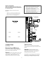
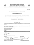
VSP-V-2001A-E
Issue 4
V-2001A-E
SINGLE ZONE (PLUS) PAGE CONTROL UNIT
INTRODUCTION
The V-2001A-E Page Control Unit is manufactured by
Valcom, Inc.
The V-2001A-E provides telephone system access to
a single zone of one-way paging.
"WARNING: To reduce the risk of fire or
electric shock, do not expose this equipment
to rain or moisture."
"WARNING: Shock Hazard - Do Not Open."
"AVIS: Risque de Choc Electrique ne pas
Ouvrir."
SPECIFICATIONS
Access Methods
"PELIGRO: Corriente Electrica - No Abra."
•
•
“CAUTION: To reduce the risk of fire replace
only with same type 1A, 125V fuse. 1A, 125V
may be replaced by a 0.5A, 250V provided
voltage selector is set for 230V.”
•
•
“DANGER: Afin de réduire le risque de feu,
remplacez le fusible par le même type de
fusible à 1A, 125V. On peut utiliser un fusible
à 0.5A, 250V pourvu que le sélecteur
dalimentation soit fixé sur 230V. Ne pas
ouvrir.”
Electronic Key System (C. O. Line Position)
PABX (Loop or Earth Call Trunk Port)
1A2 Key Systems (400 type line card required)
600 Ohm Page Port
Stand Alone Handset(s) (Used for access of the
V-2001A-E only)
Features
•
•
•
•
•
“VORSICHT: Zur verringerung von
feuergefahr die sicherung nur mit derselben
type 1A, 125V ersetzen. Statt 1A, 125V Kann
0.5A, 250V Benutzt werden, vorausgesetzt, die
spannung ist auf 230V eingestellt. Nicht
öffnen.”
“PELIGRO: Para reducir el peligro de
incendio remplazarlo unicamente con un
fusible del mismo tipo 1A, 125V. El fusible de
1A, 125V podra ser remplazado por uno de
0.5A, 250V si el selector de voltaje esta puesto
en 230V. No abres.”
•
•
•
•
•
•
•
•
•
1
Page override capability (Using C. O. line
position or loop start trunk port)
Switchable battery feed for loop start operation
RJ11 for "A" and "B" connections
AGC on all voice outputs
Provides audio for up to 150 Valcom one-way
amplified speaker assemblies
Background music input
Voice operated VOX to mute music during page
Optional contact closure activation
Easily accessible music and tone volume controls
Removable screw terminal connectors provided
Supplies 20 Valcom power units
(1 Amp -24VDC) for powering speaker amplifier
assemblies
Page with music outputs (2 provided) music
mutes during page
Page without music output
Time clock/single tone (Contact closure
activated)
947218
•
•
•
•
•
•
•
•
Night ring/warble tone
(Closure or 90VAC activated)
Priority sequence of tones:
Page overrides music
Night ring mixes with music and page
Time clock mixes with music and page
Individual switches for selection of night ring
and time clock tones per output
May be used with 25 or 70 Volt amplifiers
AC powered, 230 or 115VAC
Internationally recognized power connector
AC input fused at 0.5 Amp @ 230VAC, 50 Hz or 1
Amp @ 115VAC, 60 Hz
115/230 Volt selector switch for international use
UL listed
Dimensions/Weight
• 7.10" H x 9.00" W x 2.40" D
•
INSTALLATION
NOTE: The telephone system referred to in this
manual is the customer premise equipment such
as an electronic key system, a PABX or a
dedicated single line telephone set(s). The
V-2001A-E is not intended for direct or indirect
connection to the public telephone network or to
PABX analog station ports. When used with a
customer premise telephone system such as a
key system or PABX system, these units are
interfaced to the system via a fully protected page
port or system central office port, which is a fully
protected interface device. Also, the host system
must be configured to disallow central office
trunk conferencing in order to prevent indirect
connection to the public network.
Precautionary Designations
(18.03cm H x 22.86cm W x 6.10cm D)
3.7 lbs. (1.68kg)
CAUTION
Nominal Specifications
Input Impedance:
Input Level:
Voice Switch Sensitivity:
Music Source Input Impedance:
Music Input Level:
Output Impedance:
Output Level:
DC Output:
600 Ohms
-10dBm nominal
-21dBm
8 to 600 Ohms
-10dBm nominal
8 Ohms
-10dBm nominal
1 Amp at -24VDC
RISK OF ELECTRIC SHOCK
DO NOT OPEN
CAUTION: To reduce the risk of electric shock,
Do not remove cover.
No user serviceable parts inside.
Refer servicing to qualified service personnel.
This symbol indicates that dangerous
voltage constituting a risk of electric
shock is present within this unit.
Nominal Power Requirements
Voltage:
Current:
230VAC 0.5 Amp
115VAC 1 Amp
This symbol indicates that there are
important operating and maintenance
instructions in the literature accompanying
this unit.
The V-2001A-E is equipped with a standard 3-prong
polarized MOLEX connector to allow connection of a
battery backup supply in case of AC power failure.
•
•
Mounting
Use a cord set consis ting of a minimum 18 AWG
cord and grounding type attachment plug rated a
minimum of 15A, 250V. The cord set should have
the appropriate safety approvals for the country
in which the equipment will be installed and
should be marked HAR.
The socket outlet shall be installed near the
equipment and shall be easily accessible.
Environment
Temperature:
Humidity:
0 to 40 Degrees C
0 to 85% non-precipitating
2
The V-2001A-E was designed for wall or table
mounting. Secure unit to wall studs or a suitable
brace away from heat sources or strong magnetic
fields (Motors, fans, power supplies, etc.) with the
control and terminal strip accessible. Four wood
screws are included for mounting.
Power Connections
-
NOTE: This equipment must be installed near an
AC power outlet due to the power cord being used
as a disconnect device.
-
The V-2001A-E may be used with one of the
following:
-
-
NEMA 5-15 cordset for North American use;
CEE/7 cordset for Continental European use;
BS1363 cordset for United Kingdom use.
Connect cordset to unit via IEC 320 female connector
located on one end of the cordset to IEC 320 male
appliance coupler located on the V-2001A-E.
For 115VAC use, verify fuse rating of 1 Amp and
voltage selector switch displays 115V.
For 230VAC use, verify fuse rating of 0.5 Amp and
voltage selector switch displays 230V.
After all required connections have been made, plug
the cordset into appropriate AC wall outlet.
NOTE: Battery Feed Switch
ON - E-Key or PABX Loop
Start Trunk Port Access
OFF - Page Port Access
SW1
BATT.
FEED
J3
ON
A/TIP AND
B/RING PAGE
OFF
OR
R40
V-2001A-E
TONES
VOL.
B/RING
A/TIP
A/TIP
AND
B/RING
OVR
J2
R2
MUSIC
VOL.
VACANT
C.O.PORT
OR
PAGE
PORT
PAGE B/RING
SW2
ON
OFF
PAGE A/TIP
MUSIC
TONES
Optional Background
Music Source
SW4
ON
CLOCK/STEADY TONE
OFF
CONTACT
CLOSURE
ACTIVATION
J1
INPUTS
UNA/WARBLE TONE
UNA RINGING
SW2, SW4
ON = ENABLE
OFF = DISABLE
PC
PAGE w/o
MUSIC
CAUTION:
VORSICHT:
GND
-24V
DANGER:
PELIGRO:
J8
OUTPUTS
PAGE W/
MUSIC
GND
-24V
PAGE W/
MUSIC
GND
-24V
PPCC
FIGURE 1: V-2001A-E CONNECTORS, CONTROLS, MOUNTING ORIENTATION AND ACCESS CONNECTIONS
Optional contact
operation when VOX
operation is not desired
CONNECTIONS
Page Port Access
Refer to Figure 1.
When accessing the V-2001A-E from a telephone
system page port, the battery feed switch (SW1) must
be OFF.
Electronic Key or PABX Access
When using the V-2001A-E with an electronic key
system C. O. line position or PABX trunk port, the
battery feed switch (SW1) must be ON.
Operation: Follow the telephone system
Operation: Press line key (Electronic key system)
or dial trunk access code (PABX) to connect to the
paging speakers. Make announcement. The
V-2001A-E automatically disconnects from page.
manufacturer's instructions for access to external
paging. Make announcement. The V-2001A-E
automatically disconnects from page.
The V-2001A-E voice switching circuit is activated
when the person making the page begins to speak.
When the page is completed or the person stops
3
speaking for more than two seconds, the paging
circuit turns off. Other functions of the unit remain
the same.
Connect the output of a low level music source to the
screw terminals marked "Music" on the input terminal
strip on the V-2001A-E. Adjust music volume control
on the V-2001A-E to the desired level.
Background Music
Background music may be connected to the
2001A-E when using either access method.
Background music mutes on the "page + music"
outputs when a page is made.
Night Ring and Single Tones
V-
Night ringing (Electronic warble tone) over paging is
activated by a common audible contact closure or
90VAC ring voltage.
Volume Adjustments
The page volume is set by the speakers. Adjust
speakers 1/3 to 1/2 volume initially; test and reset, if
necessary, for correct page volume.
A single tone (Time clock) over paging is provided
when the V-2001A-E is connected to a contact
closure.
There are two volume controls for individual
adjustment of:
• Background music
• Tones (Warble/single tone)
Clockwise adjustment increases volume, counter
clockwise decreases volume.
Operation: SW4 enables or disables single and
warble tones on the page with music output. SW2
enables or disables single tones and warble tones on
the page without music output only.
Page Override
TECHNICAL ASSISTANCE
Page override requires the use of a vacant C. O. line
position, vacant loop start trunk port or dedicated
single line telephone set for access (In addition to the
page port, vacant C. O. line position or vacant loop
start trunk port used for primary access of the
V2001A-E).
When trouble is reported, verify power is being
supplied to the unit and there are no broken
connections. Check voltages for proper polarity to
the one-way amplified speakers. Table 1 identifies
symptoms of some possible problems with solutions.
If a spare unit is available, substitute a spare unit for
the suspected defective unit.
Using a modular telephone cord, connect the
V2001A-E RJ11 jack labeled "Tip and Ring OVR" to the
phone system vacant C. O. line position or vacant
loop start trunk port.
Operation: Press line key (Electronic key system)
or dial trunk access code (PABX) for page override
access to connect to paging speakers (Overriding
page in progress). Make announcement. The V2001A-E disconnects when phone is hung up, reestablishing the overridden page announcement.
Assistance in troubleshooting is available from the
factory. When calling, you should have a telephone
test set, several clip leads and a VOM available, and
be calling from the job site. Call (540) 563-2000 and
ask for Technical Support, or call (540) 767-1555 for
Valcom 24-hour Faxback System or visit our website
at http://www.valcom.com.
Should repairs be necessary, contact your local
distributor for instructions.
Connection of One-Way Amplified
Speakers
The Valcom V-2001A-E provides external power of 20
power units (1 Amp, -24VDC) to operate one-way
amplified speakers. Additional power supplies are
required for a quantity of speakers using over 20
power units. When using additional power supplies,
make certain:
1)
The -24VDC outputs are not connected to
each other.
2)
Each speaker is connected to only one
power source.
4
TROUBLESHOOTING CHART
SYMPTOMS
PROBABLE CAUSES AND SOLUTIONS
1.
No output to speakers
A.
2.
No music output
B.
A.
B.
3.
No warble tone output
A.
B.
4.
No single tone output
C.
A.
B.
Check for the presence of audio on the page outputs of the V-2001A-E during a page
using a test set. Refer to installation section for connection information.
Check AC line fuse on V-2001A-E.
Using a test set, check for music on the music input terminals.
Check that speakers are connected to “page + music” outputs.
If a contact closure is provided by the telephone system, use an Ohm meter to check the
continuity of the contact closure when they are operated when a call is ringing into the
telephone system.
If ringing is used, with an AC Volt meter, check for the presence of ring voltage when a
call is ringing into the telephone system.
Check selector switches (SW2 and SW4).
Using an Ohm meter, check the contact closure on the device that is to operate the
single tone.
Check selector switches (SW2 and SW4).
NOTE: The contact closure operation of the V-2001A-E can be tested with a length of wire connected between the two terminals
of either the UNA/warble or clock/steady tone inputs.
VALCOM U.K. WARRANTY
This product, bearing the "VALCOM" trademark, excluding the batteries, is guaranteed by the manufacturer for the period of one
year from the date of purchase and will, during this period, be repaired or replaced (with the same or a similar model), at our
option, free of charge, if there is any defect due to faulty materials or workmanship. This guarantee does not cover defects
arising from accidental damage, misuse or wear and tear, and is available only to the original purchaser of the product from an
official "VALCOM" distributor or dealer.
This guarantee applies to all Valcom products purchased and used in the EEC. Products should be returned to your nearest
Valcom distributor or dealer. If, however, the product has not been purchased in the EEC country where the distributor or dealer
is located, the customer may be advised to return the product to the EEC country where the purchase originated, if parts are
unavailable, or there are other unavoidable circumstances which hinder, or prevent service being given under guarantee.
Any person claiming under this guarantee must, on returning the product, supply proof of the date of purchase and a brief
description of the nature of the fault.
NOTE: PROOF OF PURCHASE WILL BE ACCEPTED IN THE FORM OF EITHER THE ORIGINAL RECEIPT OF PURCHASE OR THIS
GUARANTEE CERTIFICATE AND SUCH RECEIPT OR CERTIFICATE MUST BEAR THE DISTRIBUTOR OR DEALERS OFFICIAL STAMP
AND THE DATE OF PURCHASE.
Charges will be made for all repairs unless either the purchase receipt or the stamped and dated Guarantee Certificate is
returned with the product.
The guarantee does not effect the Statutory Rights of the customer.
5