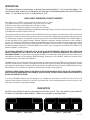
1
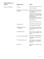
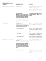
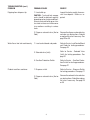
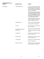
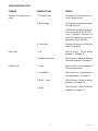
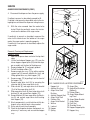
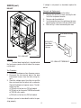
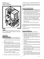
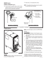
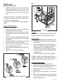
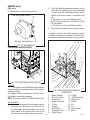
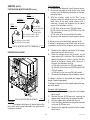
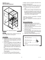
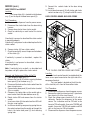
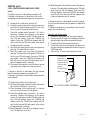
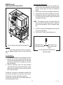
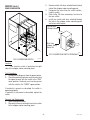
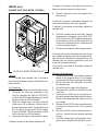
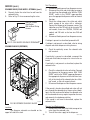
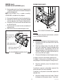
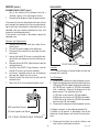
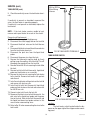
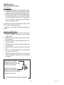
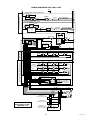
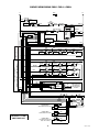
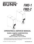
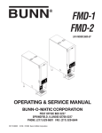
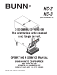
BUNN
®
FMD-2
FMD-3
(prior to S/N FMD0013000)
d
an
SH
PU
A
! W
RN
ING
TD
HOU I
LI
RE
LE
AS
EB
UT
TO
N
Q
W
TIL
UN
ON
TT
BU
LD
HO
N
HE
CU
P IS
2/3
FU
P IS
CU
2/3
SE
EA
EL
NR
HE
,T
LL
FU
LL
E
AC E
PL HER
P
CU
E
AC E
PL HER
P
CU
E
AC E
PL HER
P
CU
OPERATING & SERVICE MANUAL
BUNN-O-MATIC CORPORATION
POST OFFICE BOX 3227
SPRINGFIELD, ILLINOIS 62708-3227
PHONE: (217) 529-6601 FAX: (217) 529-6644
28364.0000D 08/02 ©1998 Bunn-O-Matic Corporation
www.bunnomatic.com
INTRODUCTION
This equipment dispenses hot beverages on demand from powdered product. It has two or three hoppers. The
two and three hopper models may also dispense cold beverages from powdered product from their left dispense
station. It is for indoor use only on a sturdy counter or shelf.
BUNN-O-MATIC COMMERCIAL PRODUCT WARRANTY
Bunn-O-Matic Corp. (“BUNN”) warrants equipment manufactured by it as follows:
1) All equipment other than as specified below: 2 years parts and 1 year labor.
2) Electronic circuit and/or control boards: parts and labor for 3 years.
3) Compressors on refrigeration equipment: 5 years parts and 1 year labor.
4) Grinding burrs on coffee grinding equipment to grind coffee to meet original factory screen sieve analysis: parts and labor for 3 years
or 30,000 pounds of coffee, whichever comes first.
These warranty periods run from the date of installation BUNN warrants that the equipment manufactured by it will be commercially
free of defects in material and workmanship existing at the time of manufacture and appearing within the applicable warranty period.
This warranty does not apply to any equipment, component or part that was not manufactured by BUNN or that, in BUNN’s judgment,
has been affected by misuse, neglect, alteration, improper installation or operation, improper maintenance or repair, damage or
casualty. This warranty is conditioned on the Buyer 1) giving BUNN prompt notice of any claim to be made under this warranty by
telephone at (217) 529-6601 or by writing to Post Office Box 3227, Springfield, Illinois 62708-3227; 2) if requested by BUNN, shipping
the defective equipment prepaid to an authorized BUNN service location; and 3) receiving prior authorization from BUNN that the
defective equipment is under warranty.
THE FOREGOING WARRANTY IS EXCLUSIVE AND IS IN LIEU OF ANY OTHER WARRANTY, WRITTEN OR ORAL, EXPRESS OR
IMPLIED, INCLUDING, BUT NOT LIMITED TO, ANY IMPLIED WARRANTY OF EITHER MERCHANTABILITY OR FITNESS FOR A
PARTICULAR PURPOSE. The agents, dealers or employees of BUNN are not authorized to make modifications to this warranty or to
make additional warranties that are binding on BUNN. Accordingly, statements by such individuals, whether oral or written, do not
constitute warranties and should not be relied upon.
If BUNN determines in its sole discretion that the equipment does not conform to the warranty, BUNN, at its exclusive option while the
equipment is under warranty, shall either 1) provide at no charge replacement parts and/or labor (during the applicable parts and labor
warranty periods specified above) to repair the defective components, provided that this repair is done by a BUNN Authorized Service
Representative; or 2) shall replace the equipment or refund the purchase price for the equipment.
THE BUYER’S REMEDY AGAINST BUNN FOR THE BREACH OF ANY OBLIGATION ARISING OUT OF THE SALE OF THIS EQUIPMENT,
WHETHER DERIVED FROM WARRANTY OR OTHERWISE, SHALL BE LIMITED, AT BUNN’S SOLE OPTION AS SPECIFIED HEREIN, TO
REPAIR, REPLACEMENT OR REFUND.
In no event shall BUNN be liable for any other damage or loss, including, but not limited to, lost profits, lost sales, loss of use of
equipment, claims of Buyer’s customers, cost of capital, cost of down time, cost of substitute equipment, facilities or services, or any
other special, incidental or consequential damages.
USER NOTICES
Carefully read and follow all notices on the equipment and in this manual. They were written for your protection.
All notices are to be kept in good condition. Replace any unreadable or damaged labels.
PUSH and HOLD BUTTON UNTIL CUP IS 2/3 FULL, THEN RELEASE
PUSH and HOLD BUTTON UNTIL CUP IS 2/3 FULL, THEN RELEASE
FMD-2
28301.0002
FMD-3
2
28301.0000
28364 080202
USER NOTICES (cont.)
00656.0000
00831.0000
160°
+
190°
TEMPERATURE
ADJUSTMENT
HEATER
26527.0002
THERMOSTAT ASSEMBLY
BUNN-O-MATIC CORP
120VAC
MECHANICAL THERMOSTAT
28368.0000
®
ELECTRONIC THERMOSTAT
26536.0002
RELEASE BUTTON WHEN CUP IS 2/3 FULL
PLACE
CUP HERE
PLACE
CUP HERE
FMD-2
28328.00003
FMD-3
28328.0000
3
28364 071598
INITIAL SET-UP
1.
2.
3.
4.
Locate the drip tray assembly beneath the dispenser nested in the packing material.
Remove the drip tray and the drip tray cover and set them aside.
Remove the water strainer assembly from the drip tray and set it aside.
Remove the four legs from the drip tray, apply non-skid pads to the bottom of the legs and securely install
the legs in the dispenser base.
ELECTRICAL REQUIREMENTS
CAUTION - The dispenser must be disconnected from the power source until specified in Initial Set-Up.
The 120 volt version of this dispenser has an attached cordset. The mating connector must be a NEMA 5-15R.
The 120/208 volt and the 120/240 version of this dispenser has an attached cordset. The mating connector must
be a NEMA 14-20R.
The 240 volt version of this dispenser has an attached cordset without plug.
ELECTRICAL HOOK-UP
CAUTION - Improper electrical installation will damage electronic components.
1.
2.
3.
4.
5.
An electrician must provide electrical service as specified.
Using a voltmeter, check the voltage and color coding of each conductor at the electrical source.
Open the front door of the dispenser and place the heater switch in the “OFF” (upper position).
Connect the dispenser to the power source.
If plumbing is to be hooked-up later be sure the dispenser is disconnected from the power source. If
plumbing has been hooked-up, the dispenser is ready for Initial Fill & Heat.
PLUMBING REQUIREMENTS
This dispenser must be connected to a COLD WATER system with operating pressure between 20 and 90 psi (138
and 620 kPa) from a 1⁄2" or larger supply line. A shut-off valve should be installed in the line before the dispenser.
Install a regulator in the line when pressure is greater than 90 psi (620 kPa) to reduce it to 50 psi(345 kPa). The
water inlet fitting is 1⁄4" flare.
NOTE - Bunn-O-Matic recommends 1⁄4" copper tubing for installations of less than 25 feet and 3⁄8" for more than
25 feet from the 1⁄2" water supply line. At least 18 inches of an FDA approved flexible beverage tubing, such as
reinforced braided polyethylene or silicone, before the dispenser will facilitate movement to clean the countertop.
It can be purchased direct from Bunn-O-Matic (part number 00326-0000). Bunn-O-Matic does not recommend
the use of a saddle valve to install the dispenser. The size and shape of the hole made in the supply line by this
type of device may restrict water flow.
This equipment must be installed to comply with the Basic Plumbing Code of the Building
Officials and Code Administrators International, Inc. (BOCA) and the Food Service Sanitation Manual of the Food and Drug Administration (FDA).
4
28364 051100
PLUMBING HOOK-UP
1. Securely attach the short piece of tubing on the water strainer assembly to the inlet fitting on the bottom of
the dispenser.
2. Flush the water line and securely attach it to the flare fitting on the water strainer assembly.
3. Turn-on the water supply.
INITIAL FILL & HEAT
CAUTION - The dispenser must be disconnected from the power source throughout the initial fill & heat, except
when specified in the instructions.
1.
2.
Turn-on the water supply and connect the dispenser to the power source.
Water will automatically flow into the tank to the proper level and then shut-off. This will take less than five
minutes.
3. When the tank is full of water, open the front door and place the heater switch in the “ON” (lower) position.
A tank full of cold water will take approximately forty minutes for the water to heat on 120 volt versions, and
twenty minutes on 120/240 and 240 volt versions.
During this waiting period, complete these dispenser set-up steps:
a. Place a set of keyholes in the splash panel over the screws beneath the hopper access door and push down
gently.
b. Place the drip tray onto the supports on the splash panel. Hook the tabs on the rear of the drip tray through
the holes in the splash panel. Set the drip tray cover in place.
c. Fill the hopper(s) with the dry product to be dispensed.
DISPENSER USE
1. Simply place a cup on the drip tray beneath the desired dispensing tip.
2. Press the button to froth and dispense the beverage.
3. Release the button when the cup is approximately 2/3 full and allow the mixing chamber to drain.
NOTE - The mixing chamber must drain at the end of each dispense.
COLD BEVERAGE SET-UP (OPTIONAL)
Cold beverages may be dispensed from the left dispense position on the FMD-2 & FMD-3 models. Simply
place the HOT/COLD switch near the left whipper chamber in the “COLD” (upper) position.
CLEANING
Refer to the decal inside the hopper access door for cleaning recommendations and procedures.
The use of a damp cloth rinsed in any mild, non-abrasive, liquid detergent is recommended for cleaning all
surfaces on Bunn-O-Matic equipment.
ADJUSTMENTS
The hot or cold beverage solenoid(s) is (are) preset to dispense approximately one ounce per second. This
amount can be adjusted:
1. Disconnect the dispenser from the power source.
2. Remove the small left side access panel.
3. Rotate the control at the base of the desired solenoid(s) clockwise to decrease or counterclockwise to
increase the amount of water.
4. For cold beverage adjustment remove the 1-1/2” plug on the lower left side of the dispenser and rotate the
needle valve clockwise to decrease or counterclockwise to increase the amount of cold water.
5
28364 011598
DRAINING THE HOT WATER TANK
CAUTION - The dispenser must be disconnected from the power source throughout these steps.
1. Disconnect the dispenser from the power source.
2. Open front door and place tank heater switch in the “OFF” (upper) position.
3. Shut-off and disconnect the incoming water supply.
4. Remove the top panel.
5. Gently remove one of the grommets from the tank lid.
6. Insert a tube to the bottom of the tank and syphon ALL of the water out.
(Bunn-O-Matic has a syphon assembly #12440.0000 available for this purpose.)
NOTE - The dispenser must be refilled using the INITIAL FILL & HEAT steps before reconnecting to the power
source.
HOPPER DISPENSE RATE OF PRODUCT
1.
2.
3.
Hopper dispense rate with 22 tooth gear and auger wire is approximately 4 to 6 grams per second.
Hopper dispense rate with 22 tooth gear and auger wire with optional restrictor is approximately 3 to 5
grams per second.
Hopper dispense rate with optional 32 tooth gear and auger wire is 6 to 9 grams per second.
TROUBLESHOOTING
A troubleshooting guide is provided to suggest probable causes and remedies for the most likely problems
encountered. If the problem remains after exhausting the troubleshooting steps, contact the Bunn-O-Matic
Technical Service Department.
•
•
•
•
•
•
•
Inspection, testing, and repair of electrical equipment should be performed only by qualified service personnel.
All electronic components have 120 volt ac or 240 volt ac and low voltage dc potential on their terminals.
Shorting of terminals or the application of external voltages may result in board failure.
Intermittent operation of electronic circuit boards is unlikely. Board failure will normally be permanent. If an
intermittent condition is encountered, the cause will likely be a switch contact or a loose connection at a
terminal or crimp.
Solenoid removal requires interrupting the water supply to the valve. Damage may result if solenoids are
energized for more than ten minutes without a supply of water.
The use of two wrenches is recommended whenever plumbing fittings are tightened or loosened. This will help
to avoid twists and kinks in the tubing.
Make certain that all plumbing connections are sealed and electrical connections tight and isolated.
This unit is heated at all times. Keep away from combustibles.
WARNING – •
•
•
•
Exercise extreme caution when servicing electrical equipment.
Unplug the dispenser when servicing, except when electrical tests are specified.
Follow recommended service procedures
Replace all protective shields or safety notices
6
28364 011598
TROUBLESHOOTING (cont.)
PROBLEM
PROBABLE CAUSE
REMEDY
Product will not dispense
1. No water
Water lines and valves to the dispenser must be open.
2. No power or incorrect voltage to
the dispenser
(A1) Check for 120 volts across the
black and white wires on two wire
120 volt dispenser.
(A2) Check for 120 volts across the
red and white wires and the black
and white wires on three wire 120/
240 volt dispenser.
(A3) Check for 240 volts across the
white and black wires on two wire
240 volt dispenser.
(B) Check circuit breakers or fuses.
3. Dispense switch
Refer to Service - Dispense Switch
for testing procedure. See page 17
4. Dispense solenoid valve
(Hot or Cold)
Refer to Service - Dispense solenoid
valve for testing procedures. See
page 29 or 30
5. Solenoid valve (Inlet)
Refer to Service - Solenoid Valve
(Inlet) for testing procedures. See
page 31
6. Level control board and probe
Refer to Service - Level Control Board
and Probe for testing procedures.
See page 24
7. Overflow protection switch
Refer to Service - Overflow protection switch for testing procedures.
See page 27
8. Auger drive
Refer to Service - Auger Drive. See
page 12
7
28364 011598
TROUBLESHOOTING (cont.)
PROBLEM
PROBABLE CAUSE
REMEDY
Product will not dispense (cont.)
9. Water strainer
(A) Direction of flow arrow must be
pointing towards dispenser.
(B) Remove the strainer and check
for obstructions. Clear or replace.
Water is not hot
Spitting or excessive steaming
10. Lime build-up
CAUTION - Tank and tank components should be delimed regularly
depending on local water conditions.
Excessive mineral build-up on stainless steel surfaces can initiate corrosive reactions resulting in serious
leaks.
Inspect the tank assembly for excessive lime deposits. Delime as required.
1. Limit thermostat
CAUTION - Do not eliminate or bypass limit thermostat. Use only BOM
replacement part #29329.1000
Refer to Service - Limit Thermostat
for testing procedures. See page 26
2. Control thermostat
Refer to Service - Control Thermostat for testing procedures. See page
16
3. Tank Heater
Refer to Service - Tank Heater for
testing procedures. See page 32
4. Tank heater switch
Refer to Service - Tank Heater Switch
for testing procedures. See page 33
1. Lime build-up
CAUTION - Tank and tank components should be delimed regularly
depending on local water conditions.
Excessive mineral build-up on stainless steel surfaces can initiate corrosive reactions resulting in serious
leaks.
Inspect tank assembly for excessive
lime deposits. Delime as required.
2. Control thermostat
Refer to Service - Control Thermostat for testing procedures. See
page 16
8
28364 051100
TROUBLESHOOTING (cont.)
PROBLEM
Dripping from dispense tip
Water flows into tank continuously
Product overflows container
PROBABLE CAUSE
REMEDY
1. Lime build-up
CAUTION - Tank and tank components should be delimed regularly
depending on local water conditions.
Excessive mineral build-up on stainless steel surfaces can initiate corrosive reactions resulting in serious
leaks.
Inspect the tank assembly for excessive lime deposits. Delime as required.
2. Dispense solenoid valve (Hot or
Cold)
Remove the dispense solenoid valve
and clear any obstructions. Rebuild
or replace the valve if necessary. See
page 29 or 30
1. Level control board and probe
Refer to Service - Level Control Board
and Probe for testing procedures.
See page 24
2. Solenoid valve (Inlet)
Refer to Service - Solenoid Valve
(Inlet) for testing procedures. See
page 31
3. Overflow Protection Switch
Refer to Service - Overflow Protection Switch for testing procedures.
See page 27
1. Dispense switch
Refer to Service - Dispense Switch
for testing procedures. See page 17
2. Dispense solenoid valve (Hot or
Cold)
Remove the solenoid valve and clear
any obstructions. Rebuild or replace
the valve if necessary. See page 29
or 30
9
28364 011598
TROUBLESHOOTING (cont.)
PROBLEM
PROBABLE CAUSE
REMEDY
Weak product
1. Water temperature
Place an empty container beneath
the dispense tip. Initiate a dispense
cycle and check the water temperature immediately below the dispense
tip with a thermometer.
(A) Reading for mechanical thermostat models should be 180°F to 200°F
(see thermostat temperature settings
decal in USER NOTICES on page 3.
(B) Reading for electronic thermostat should be185°F to 190°F.
Adjust the control thermostat to increase or decrease the water temperature. Replace if necessary.
2. Whipper motor
Refer to Service - Whipper Motor for
testing procedure. See page 19
3. Frother
Refer to Service - Frother Components. See page 19
4. Dispense solenoid valve
(Hot or Cold)
Refer to Service - Dispense Solenoid
Valve for test procedures. See page
29 or 30
5. Auger drive
Refer to Service - Auger Drive Components. See page 12
6. Auger spring
Refer to Service - Auger Drive Components. See page 12
7. Auger motor
Refer to Service - Auger Drive Components. See page 14
8. Rinse/Run switch
Refer to Service - Rinse/Run Switch
for test procedures. See page 28
10
28364 011598
TROUBLESHOOTING (CONT.)
PROBLEM
PROBABLE CAUSE
REMEDY
Dispenser is making unusual
noises
1. Plumbing Lines
Plumbing lines should not be resting on the counter top.
2. Water Supply
(A) The dispenser must be connected
to a cold water line
(B) Water pressure to the dispenser
must not exceed 90 psi 620 kPa).
Install a regulator if necessary to
lower the working pressure to approximately 50 psi (345 kPa).
Excess dust
Display not lit
3. Tank Heater
Remove and clean lime off the tank
heater. See page 32
1. Fan
Refer to Service - Fan for testing
procedures. See page 18
2. Hopper Delay Board
Refer to Service - Hopper Delay Board
for testing procedures. See page 21
1. Lamp
Refer to Service - Lamp, see page 23
for lamp replacement.
2. Lamp Holder
Refer to Service - Lamp Holder for
testing procedures. See page 23
3. Starter - Lamp
Refer to Service - Starter for testing
procedures. See page 24
4. Ballast
Refer to Service - Ballast for testing
procedures. See page 15
11
28364 051100
AUGER DRIVE COMPONENTS
SERVICE
This section provides procedures for testing and
replacing various major components used in this
dispenser should service become necessary. Refer to
Troubleshooting for assistance in determining the
cause of any problem.
WARNING - Inspection, testing, and repair of electrical equipment should be performed only by qualified
service personnel. The dispenser should be unplugged when servicing, except when electrical tests
are required and the test procedure specifically states
to plug-in the dispenser.
COMPONENT ACCESS
WARNING - Disconnect the dispenser from the power
source before the removal of any panel or the replacement of any component.
All components are accessible by opening the
door, removal of the door panels, dispenser top covers, hoppers, hopper support plate, splash
guard,splash panel w/drip tray, lower front access
panel, side and rear access covers.
P1445.40
FIG. 1 AUGER DRIVE COMPONENTS
Location
The auger components are located inside
the bottom part of the hopper except for the auger
drive bracket, washer and locknut, which are located
on the outside bottom rear of the hopper. The auger
motors are located on the rear of the auger motor
mounting panel. Refer to Fig. 2 for disassembly and
assembly.
Contents
Auger Drive Components ...................................... 12
Auger Motor ......................................................... 14
Ballast ................................................................... 15
Control Thermostat ............................................... 16
Dispense Switch ................................................... 17
Fan ........................................................................ 18
Frother ................................................................. 19
Hopper Delay Board .............................................. 21
Hot/Cold Switch .................................................... 22
Lamp Holder ......................................................... 23
Lamp .................................................................... 23
Lamp Starter and Socket ...................................... 24
Level Control Board and Level Probe .................... 24
Limit Thermostat .................................................. 26
Overflow Protection Switch .................................. 27
Rinse/Run Switch ................................................. 28
Solenoid (Cold Drink - Optional) ........................... 29
Solenoid (Dispense) ............................................. 30
Solenoid (Inlet) ..................................................... 31
Tank Heater .......................................................... 32
Tank Heater Switch ............................................... 33
Whipper Motor ..................................................... 19
Wiring Diagrams .......................................... 35 & 36
Test Procedures - Auger motors
1. Disconnect the dispenser from the power source.
2. Disconnect the wires from the motor to be tested.
3. Check the voltage across the white/violet wire for
the right motor, orange wire for the center motor
or the red wire for the left motor and the gray wire
with a voltmeter. With the rinse/run switch in the
run position press and hold the appropriate dispense switch. Connect the dispenser to the power
supply. After a .7 second delay the indication must
be :
a) 120 volts ac for two wire 120 volt models.
b) 120 volts ac for three wire 120/208 volt or 120/
240 volt models.
c) 240 volts ac for two wire 240 volt models.
12
28364 011598
SERVICE
AUGER DRIVE COMPONENTS (CONT.)
4. Disconnect the dispenser from the power supply.
1
2
If voltage is present as described, proceed to #5.
If voltage is not present as described, refer to the wiring diagrams and check the dispenser wiring harness.
3
5
5.
4
11
6
13
With the wires removed from the motor to be
tested. Check for continuity across the two terminals on the bottom of the auger motor.
7
12
14
8
9
10
If continuity is present as described, reconnect the
wires to the terminals on the bottom of the auger
motor, the auger motor is operating properly.
If continuity is not present as described, replace the
auger motor.
21
Removal, Cleaning and Replacement
Hopper & Auger
1. Open the dispenser door and raise the top front
cover.
2. Lift the front edge of hopper assy (21) over the
tab on hopper support plate (20) and slide hopper assembly out the front of the dispenser.
3. Remove hopper lid (1) and empty product.
4. Pull off the ejector elbow (14).
5. Remove auger disc assy (2) by pulling agitator
support rod (4) towards agitator disc assy and
lifting agitator disc assy from hopper (10).
6. Remove auger (12) by pulling it out the front of
the hopper (10).
7. Remove auger drive shaft (5) by removing the
retaining clip (6) from auger drive shaft.
8. Slide washer (8) and auger drive shaft bracket
(7) off of the auger drive shaft (5).
9. Slide auger drive shaft (5) from auger drive shaft
bushing (3) and remove from hopper (10).
10. Remove locknut (9) from auger drive shaft bushing (3) and remove auger drive shaft bushing
from hopper (10).
11. Wash components in a mild solution of dish detergent using a bristle brush when needed.
12. Rinse and dry each item thoroughly.
13. Check for damaged or broken components, replace any if necessary and reassemble hopper
assy.
16 17 18 15 19 20
P1446.75
FIG. 2 AUGER DRIVE & HOPPER DISASSEMBLY
12. Auger Wire
1. Hopper Lid
13. Auger Wire/Restrictor
2. Agitator Disc Assy
(Optional)
3. Auger Drive Shaft
14. Ejector Elbow
Bushing
4. Agitator Support Rod 15. Auger Motor Mounting Panel
5. Auger Drive Shaft
16. Auger Motor Bracket
6. Retainer Clip
7. Auger Drive Bracket 17. Auger Motor
18. Dust Seal
8. Washer
19. Shoulder Screw
9. Locknut
20. Hopper Support plate
10. Hopper
21. Hopper Assy
11. Spring
13
28364 011598
(17) to the rear of the auger motor mounting panel
(15).
4. Disconnect the wires from the auger motor (17) to
be removed.
5. Remove auger motor mounting bracket (16), auger motor (17) and dust seal (18) as an assembly.
6. Remove dust seal (18) from auger motor (17).
7. Remove the four #8-32 screws securing the auger
motor to the auger motor mounting bracket.
8. Remove auger motor and discard.
9. Using four #8-32 screw install new auger motor
(17) on mounting bracket (16).
10. Install dust seal (18) on auger motor shaft.
11. Using four #8-32 locking screws install auger
motor, dust seal and mounting bracket to the rear
of the auger motor mounting panel (15)
12. Reconnect the wires to the terminals on the bottom of the auger motor.
13. Install hopper support plate (20) and hopper assembly (21).
14. Refer to Fig. 3 when reconnecting wires.
SERVICE (cont.)
AUGER DRIVE COMPONENTS (cont.)
14. Install hopper assy (21) in the dispenser by sliding
hopper assy in the guides on the hopper support
plate (20) until the slot in the bottom rear the
hopper seats against the shoulder screw (19) in
the hopper support plate.
Auger Drive Motor (Refer to Fig. 2)
1. Remove hopper assy (21) and set aside for reassembly.
2. Remove the the four #8-32 screws securing the
hopper support plate (20), remove plate and set
aside for reassembly.
3. Remove the four #8-32 locking screws, located
inside the dispenser housing on the front of the
auger motor mounting panel (15), securing auger
motor mounting bracket (16) and auger motor
LEFT FMD-2 & 3
GRY to Hopper Delay
Circuit Board #6
RED from Hopper
Delay Circuit Board #5
CENTER FMD-3 ONLY
GRY to Hopper Delay
Circuit Board #3
ORA from Hopper
Delay Circuit Board #2
RIGHT FMD-2 & 3
GRY to
Hopper Delay
Circuit Board
#7
WHI/VIO from Hopper
Delay Circuit Board #1
P1201
FIG. 3 AUGER MOTOR TERMINALS
14
28364 041598
If voltage is not present as described, replace the
ballast.
SERVICE (cont.)
BALLAST
Removal and Replacement
1. Disconnect the wires from the ballast.
2. Remove the one #8-32 screw securing the ballast to the component bracket.
3. Remove and discard ballast.
4. Install new ballast over the weld pin on the component bracket and secure with one #8-32 screw.
5. Refer to Fig. 5 when reconnecting the wires.
BLK to Main Wiring
Harness
BLK to BLU
from Door
Interconnect
Harness
FIG. 4 BALLAST
P1445
Location
The front door lamp ballast is located behind
the front access panel on the left side of the component bracket.
FIG. 5 BALLAST TERMINALS
P1447
Test Procedure
1. Disconnect the dispenser from the power source.
2. Disconnect the two terminal plug of the door
interconnect harness from the main wiring harness.
3. Check the voltage across the white wire and the
blue wire terminal of the ballast with a voltmeter.
Connect the dispenser to power source. The indication must be:
a) 120 volts ac for two wire 120 volt models.
b) 120 volts ac for three wire 120/208 volt models
or 120/240 volts models.
c) 240 volts ac for two wire 240 volt models.
If voltage is present as described the ballast is operating properly.
15
28364 011598
If voltage is present as described the control thermostat is operating properly. Reinstall bulb into the tank.
If voltage is not present as described, replace the thermostat.
SERVICE (cont.)
CONTROL THERMOSTAT
Electronic Thermostat (Optional)
1. Disconnect the dispenser from the power source.
2. Disconnect the black wire of the control thermostat from the black wire from the limit thermostat.
3. Remove temperature probe from the tank.
4. Check the voltage the black wire from the control
thermostat and the white or red wire on the tank
heater with the tank heater switch in “ON” lower
position with a voltmeter. Connect the dispenser
to the power source. The indication must be:
a) 120 volts ac for two wire 120 volt models.
b) 120 volts ac for three wire 120/208 volt or 120/
240 volt models.
c) 240 volts ac for two wire 240 volt models.
FIG. 6 CONTROL THERMOSTAT
If voltage is present as described the control thermostat is operating properly. Reinstall temperature probe
into the tank.
If voltage is not present as described, replace the
control thermostat.
P1445
Location
The control thermostat (mechanical or electronic) is located inside the dispenser on the upper
left side of the housing.
Removal and Replacement.
1. Disconnect the wires from the thermostat.
2. Remove the thermostat capillary bulb by firmly
pulling-up on the capillary at the tank lid. This will
disengage the grommet from the tank lid.
3. Loosen the two #8-32 screws securing the thermostat bracket to the upper left rear of the dispenser housing.
4. Remove thermostat bracket and thermostat as an
assembly.
5. Remove the two #6-32 screws securing the thermostat to the thermostat bracket and discard
thermostat.
6. Install new thermostat on the thermostat bracket
using two #6-32 screws.
7. Install the thermostat and bracket inside the dispenser housing on the upper left rear side and
tighten the two #8-32 screws.
8. Slide the grommet to the line 4.5” above the bulb
on the new capillary tube.
9. Insert the capillary bulb through the hole in the
tank lid and press the grommet firmly and evenly
so that the groove in the grommet fits into the tank
lid.
Test Procedure
Mechanical Thermostat
1. Disconnect the dispenser from the power source.
2. Disconnect the black wire of the control thermostat from the black lead from the limit thermostat.
3. Remove bulb from the tank.
4. Check the voltage across black wire on the control thermostat and the white or red wire on the
tank heater with the tank heater switch in the “ON”
lower position with a voltmeter. Connect the dispenser to the power source. The indication must
be:
a) 120 volts ac for two wire 120 volt models.
b) 208 volts ac for three wire 120/208 volt or 240
volts ac for 120/240 volt models.
c) 240 volts ac for two wire 240 volt models.
5. Disconnect the dispenser from the power source.
16
28364 071598
SERVICE (cont.)
11. Refer to Fig. 7 and reconnect the wires.
CONTROL THERMOSTAT (cont.)
NOTE - The capillary tube must be clear of any electrical termination and not kinked.
10. Carefully bend the capillary tube so that the tube
and bulb inside the tank are in the vertical position
and away from any electrical connections.
TAN to WHI/BRN
on Tank Heater Switch
BLK to Main
Wiring Harness
WHI to Main
Wiring Harness
BLK from Limit
Thermostat
BLK from Tank
Heater Switch
BLK to Limit
Thermastat
ELECTRONIC THERMOSTAT
MECHANICAL THERMOSTAT
FIG. 7 THERMOSTAT TERMINALS
P1448
DISPENSE SWITCH
NOTE: The center dispense switch is for FMD-3 Models only.
EA
HE
NR
Test Procedure:
1. Disconnect the dispenser from the power source.
2. Open the dispenser door and remove the bottom
door cover.
3. Disconnect the wires from the door interconnect
wiring harness to the dispense switch to be
tested.
4. Check for voltage across the black and red/black
wires for the right dispense switch, black and
red/white wires for the center dispense switch or
the black and red wires for the left dispense
switch from the door interconnect wiring harness. Connect the dispenser to the power supply.
The indication must be:
a) 120 volts ac for two wire 120 volt models.
b) 120 volts ac for three wire 120/208 volt or 120/
240 volt models.
c) 240 volts ac for two wire 240 volt models.
5. Disconnect the dispenser from the power source.
SE
EL
,T
LL
TIL
TO
CU
P IS
2/3
FU
N
NU
UT
DB
OL
dH
SH
an
PU
G
NIN
AR
! W
ID
U
Q EN
LI
OT
H
RE
LE
AS
EB
T
UT
ON
WH
C
IS
UP
2/3
FU
LL
CE
PLA ERE
PH
CU
CE
PLA ERE
PH
CU
CE
PLA ERE
PH
CU
FIG.8 DISPENSE SWITCH
P1436
Location:
The dispense switches are located on the lower
outside of the dispenser door.
If voltage is present as described, proceed to #6.
If voltage is not present as described, refer to the wiring diagram and check the dispenser wiring harness.
17
28364 071598
FAN
SERVICE (cont.)
DISPENSE SWITCH (cont.)
6.
Check for continuity across the terminals on the
dispense switch with the switch in the “ON”
pressed position. Continuity must not be present
when the switch is in the “OFF” released position.
If continuity is present as described, reconnect the
connector to the door interconnect wiring harness,
the switch is operating properly.
If continuity is not present as described, replace the
switch.
Removal and Replacement
1. Open the dispenser door.
2. Remove the five #6-32 screws securing the bottom door cover and remove cover.
3. Disconnect the wires on the dispense switch to
be removed from the door interconnect wiring
harness.
4. Compress the clips inside the door on the dispense switch and gently push the switch through
the opening.
5. Push new switch into the opening and spread
the clips to hold the switch in the door.
6. Reconnect the wires to the dispense switch from
door interconnect wiring harness.
7. Reinstall the door bottom cover using five #6-32
screws.
8. Refer to Fig. 9 when reinstalling wires.
FIG. 10 FAN
P1436
Location:
The fan is located inside the dispenser housing on the right rear of the dispenser base plate.
Test Procedures:
1. Disconnect the dispenser from the power source.
2. Disconnect the black and white wires from the
fan terminals.
3. Check the voltage across the black and white
wires with a voltmeter. Connect the dispenser to
the power source. The indication must be:
a) 120 volts ac for two wire 120 volts models.
b) 120 volts ac for three wire 120/208 volt or 120/
240 volt models.
c) 240 volts ac for two wire 240 volt models.
BLK
RED/BLK
If voltage is present as described, replace the fan
If voltage is not present as described, refer to wiring
diagram and check the dispenser wiring harness.
BLK
RED/WHI
BLK
RED
Removal and Replacement:
1. Disconnect the vacuum hose from the fan.
2. Remove the two #8-32 locking screws securing
the fan to the dispenser housing base plate.
3. Disconnect the wires from the fan terminals and
discard the fan
4. Refer to Fig.11 and connect the wires to the new
fan.
5. Install new fan through the rear access hole and
secure to the dispenser housing base plate using
two #8-32 locking screws.
RIGHT
FMD 2 & 3
CENTER
FMD-3 ONLY
LEFT
FMD 2 &3
FIG. 9 DISPENSE SWITCH TERMINALS
P1449
18
28364 071598
SERVICE (cont.)
3.
Press and hold the appropriate dispense switch
and check the voltage across the disconnected
harness wires with a voltmeter. Connect the dispenser to the power source. The reading must
be:
a) 120 volts ac for two wire 120 volt models.
b) 120 volts ac for three wire 120/208 volt or 120/
240 volt models.
c) 240 volts ac for two wire 240 volt models.
4. Disconnect the dispenser from the power source.
FAN (cont.)
6. Reconnect the vacuum hose to the fan.
BLK from Control Harness
If voltage is present as described, replace the motor.
If voltage is not present as described, refer to the wiring diagrams and check the dispenser wiring harness.
WHI from Control Harness
15 16 17
P1507
FIG. 11 FAN TERMINALS
FROTHER AND WHIPPER MOTOR
1
12
13
14
11
P1450.40
FIG. 11 FROTHER AND WHIPPER MOTOR
Location:
The frothers are located behind the dispenser
door, mounted on the whipper motor shaft inside the
whipper chamber.
The whipper motors are located on the back side of
the whipper motor mounting panel.
NOTE: The center position is for FMD-3 Models only.
Test Procedure:
1. Disconnect the dispenser from the power source.
2. Disconnect the white/violet and white wires on
the right motor, orange and white wires on the
center motor or the red and white wires on the
left motor from the black leads on the motors.
2
10
9
8
7 6
5 4 3
FIG. 12 MIXING/WHIPPER CHAMBER
COMPONENTS
1.
2.
3.
4.
5.
6.
7.
8.
9.
19
Steam Collector
Mixing Chamber
Dispense Tip
Whipper Chamber
O-Ring
Frother
#6-32 Screw
Receptical w/Seal
Teflon Washer
10.
11.
12.
13.
14.
15.
16.
17.
P1440.35
O-Ring
#8-32 Acorn Nut
Motor Assy.
Washer
Nut
Fan
Vacuum Hose
Baffle
28364 071598
19. Wash remaining components in a mild solution of
dish detergent using a bristle brush.
20. Rinse thoroughly and allow to dry before reinstalling in the dispenser.
21. Place teflon washer into back opening of whipper
chamber receptical and align one notch with bump
in the opening.
22. Slide whipper chamber receptacle w/seal on to the
motor shaft and secure to the front panel using two
#6-32 screws (7).
23. Slip o-ring (5) onto the whipper chamber receptical
(8).
24. Push frother (6) onto the motor shaft, making sure
the flat in the frother (6) lines up with the flat on the
motor shaft.
25. Install whipper chamber (4) on the whipper chamber receptical (8) by twisting counterclockwise
until the tabs on the whipper chamber (4) lock with
the tabs on the whipper chamber receptical (8). Be
sure dispense port is pointing down.
26. Install dispense tip (3) into the bottom of the
whipper chamber (4). Be sure the cutout part of
the dispense tip is facing the outside of the dispenser.
27. Using two #4-40 screws secure the fan baffle to
the to the whipper motor mounting panel.
28. Install vacuum hose (16) on fan baffle (17).
29. Install hopper support panel using four #8-32
screws.
30. Slip the mixing chamber (2) onto the mixing
chamber water inlet tube far enough so the mixing
chamber (2) will seat inside the whipper chamber
(4).
31. Install the steam collector (1) onto the mixing
chamber (2) by pushing down and toward the
dispenser while twisting until the flange on the
steam collector lines-up with the slot in the front
panel.
32. Install hopper assembly in the dispenser by sliding
hopper assembly on the hopper support panel
until the slot in the bottom rear of the hopper seats
against the shoulder screw in the hopper support
panel.
SERVICE (cont.)
FROTHER AND WHIPPER MOTOR (cont.)
Removal, Cleaning and Replacement (Refer to Fig. 12):
1. Open the dispenser door and raise the top front
cover.
2. Lift the front edge of the each hopper assembly
over the tab on the hopper support panel and
slide each hopper assembly out the front of the
dispenser. Set aside for reassembly.
3. Remove the four #8-32 screws securing the hopper support panel to auger motor mounting panel
and the whipper motor mounting panel. Set aside
for reassembly.
4. Disconnect vacuum hose (16) from fan baffle
(17).
5. Remove the two #4-40 x .25" screws securing
the fan baffle(17) to the whipper motor mouting
panel and remove fan baffle. Set aside for reassembly.
6. Remove the steam collector (1) by pulling it forward and at the same time twisting it clockwise.
7. Pull the mixing chamber (2) out of the whipper
chamber (4).
8. Remove dispense tip (3) and twist the whipper
chamber (4) clockwise and pull it off the whipper
chamber receptacle (8).
9. Pull the frother (6) off the motor shaft. Notice the
flat side on the shaft and the matching flat inside
the frother. It is important that these two flats are
lined up when reassembling.
10. Slip the o-ring (5) off the whipper chamber
receptical (8).
11. Remove the two #6-32 screws (7) securing whipper chamber receptical (8) to the front panel.
12. Slide the receptical w/seal off of the motor shaft.
13. Slide teflon washer (9) and o-ring (10) off of the
motor shaft.
14. Disconnect the black leads on the motor (12) from
the main wiring harness.
15. Remove the two #8-32 acorn nuts (11) securing
the motor (12) to the rear of front panel.
16. Remove motor and discard.
17. Install new motor (12) on rear of front panel and
secure with two #8-32 acorn nuts (11) and connect black leads on the motor to the main wiring
harness. Refer to FDig. 13 when reconnecting
wires
18. Slide o-ring (10) onto the motor shaft to approximately 1/16" of the front panel.
20
28364 011598
SERVICE (cont.)
Test Procedures:
1. Disconnect the dispenser from the power source.
2. Disconnect the eight pin plug on the main wiring
harness from the eight pin connector on the hopper delay board.
3. With the rinse/run switch in the “Run”, lower
position, check the voltage across the white and
black wires of the main wiring harness with a
voltmeter. Connect the dispenser to the power
source. The indication must be:
a) 120 volts ac for two wire 120 volt models.
b) 120 volts ac for three wire 120/208 volt or 120/
240 volt models.
c) 240 volts ac for two wire 240 volt models.
4. Disconnect the dispenser from the power source.
FROTHER AND WHIPPER MOTOR (cont.)
RIGHT
FMD- 2 & 3
CENTER
FMD-3 ONLY
LEFT
FMD-2 & 3
BLK to Main
Harness WHI/VIO
BLK to Main
Harness WHI
BLK to Main Harness ORA
BLK to Main Harness WHI
BLK to Main Harness RED
BLK to Main Harness WHI
FIG.13 WHIPPER MOTOR TERMINALS
If voltage is present as described, proceed to #5.
If voltage is not present as described, refer to the wiring diagram and check the dispenser wiring harness.
P1451.40
5.
HOPPER DELAY BOARD
6.
7.
Reconnect the eight pin connector of the hopper
delay board to the main harness.
Check the voltage across the terminals on the
auger motor with a voltmeter. Press and hold the
appropriate dispense switch. Connect the dispenser to the power source. After a delay of .7
seconds the indication must be:
a) 120 volts ac for two wire 120 volt models.
b) 120 volts ac for three wire 120/208 volt or 120/
240 volt models.
c) 240 volts ac for two wire 240 volt models.
Disconnect the dispenser from the power source.
If voltage is present as described the hopper delay
board is operating properly.
If voltage is not present as described, replace the hopper delay board.
FIG. 14 HOPPER DELAY BOARD
Removal and Replacement:
1. Disconnect the eight pin plug from the hopper
delay board.
2. Remove the two #8-32 keps nuts securing the
hopper delay board to the component bracket.
3. Remove hopper delay board and discard.
4. Install new delay board on the component bracket
using two #8-32 keps nuts.
5. Reconnect the eight pin connector to the hopper
delay board.
P1445.40
Location
The hopper delay board is located behind the
lower front access panel mounted in the center of the
component bracket.
21
28364 011598
SERVICE (cont.)
If voltage is present as described, reconnect the four
pin plugs and proceed to #5.
If voltage is not present as described, refer to the
wiring diagram and check the main wiring harness.
HOT/COLD SWITCH (Optional)
5.
6.
Disconnect the wires from the switch terminals.
With the switch in the upper “Cold” position check
for continuity between the center terminal and
the bottom terminal. With the switch in the down
“Hot” position check for continuity between the
center terminal and the upper terminal.
If continuity is present as described, the hot/cold
switch is operating properly.
If continuity is not present as described, replace the
switch.
FIG. 15 HOT/COLD SWITCH
Removal and Replacement:
1. Remove all wires from the switch terminals.
2. Remove the mounting nut on the front of the
whipper motor mounting panel.
3. Remove the hot/cold switch from the rear of the
front panel and discard.
4. Reconnect the wires to the terminals on the rear
of the new switch.
5. Push new hot/cold switch through the hole on
the left side of the whipper motor mounting panel
and secure with mounting nut.
6. Refer to Fig. 16 when reconnecting the wires.
P1452.40
Location:
The hot/cold switch is located on the left side
of the whipper motor mounting panel.
Test Procedure:
1. Disconnect the dispenser from the power source.
2. Disconnect the four pin plug from the hot/cold
switch and the four pin connector on the main
wiring harness.
3. Press the left dispense switch on the door and
check the voltage across the white wire (P4) and
red wire (P2) in the four pin connector on the main
wiring harness with a voltmeter. Connect the dispenser to the power source. The indication must
be:
a) 120 volts ac for two wire 120 volt models.
b) 120 volts ac for three wire 120/208 volt or 120/
240 volt models.
c) 240 volts ac for two wire 240 volt models.
4. Disconnect the dispenser from the power source.
TAN to Main Harness
RED to Main Harness
WHI/YEL to Cold
Solenoid
FIG. 16 HOT/COLD SWITCH TERMINALS
22
P1208
28364 011598
Removal and Replacement:
1. Open dispenser door (1).
2. Remove the five #6-32 screws securing lower
door panel (5) to the door (1) and remove cover.
3. Disconnect the door wiring harness from the door
interconnect wiring harness.
4. Remove five #6-32 screws securing the upper
door panel (4) to the door.
5. Remove the upper door cover (4), lamp (3), lamp
holders (2) and door wiring harness as an assembly.
6. Disconnect the wires from the lamp holder to be
replaced from the door wiring harness.
7. Rotate lamp (3) 90° and remove from lamp holders (2).
8. Remove the #6-32 screw securing the lamp holder
(2) to be removed, remove lamp holder (2) and
discard.
9. Install new lamp holder (2) and secure with a #632 screw.
10. Connect the wires on the new lamp holder to the
door wiring harness.
11. Install lamp (3) into lamp holders (2) and turn 90°
until the pins snap in place.
12. Install upper door panel (4), lamp (3), lamp holders (2) and door wiring harness as a assembly
using five #6-32 screws.
13. Reconnect the plug on the door wiring harness to
the connector on the door interconnect wiring
harness.
14. Install the door lower panel (5) using five #6-32
screws.
SERVICE (cont.)
LAMP HOLDER
1
3
5
4
2
6
PU
SH
an
O
dH
LD
BU
TT
ON
UN
TIL
CU
P IS
2/3
FU
LL
H
,T
EN
RE
LE
AS
E
FIG. 17 LAMP HOLDERS
P1454.70
1. Door Assy
4. Upper Panel
2. Lamp Holders
5. Lower Panel
3. Lamp
6. Starter W/Socket
Location:
The lamp holders are located on the front of
the upper panel behind the display panel.
LAMP REPLACEMENT (Refer to Fig. 17)
1. Remove the outside window and display graphic.
2. Remove the two #4-40 screws securing the inside
window to the door and remove window.
3. Rotate lamp (3) 90° and remove from the lamp
holders (2).
4. Insert new lamp (3) into lamp holders (2) and turn
90° until the pins snap in place.
5. Using two #4-40 screws secure the inside window
to the door.
6. Install outside window and slide display graphic
down between the inside window and the outside
window.
Test Procedure:
1. Disconnect the dispenser from the power source.
2. Remove upper door panel (4) and disconnect the
door wiring harness from the leads on the lamp
holders.
3. Remove lamp from lamp holders.
4. Check for continuity on each lead of the lamp
holders.
If continuity is present as described, lamp holders are
operating properly.
If continuity is not present as described replace the
lamp holder.
23
28364 011598
9. Connect the sockets leads to the door wiring
harness.
10. Install door lower panel (5) with starter and starter
socket on door assy (1) using five #6-32 screws.
SERVICE (cont.)
LAMP STARTER and SOCKET
Location:
The lamp starter (6) is located inside the door
assy (1) on the top of the door lower panel (5).
LEVEL CONTROL BOARD AND LEVEL PROBE
Test Procedures:
1. Disconnect the dispenser from the power source.
2. Disconnect the starter leads from the door wiring
harness.
3. Remove lamp starter from starter socket.
4. Check for continuity on each lead of the starter
socket.
If continuity is present as described the starter socket
is operating properly.
If continuity is not present as described replace the the
starter socket.
6. Remove starter (6) from starter socket.
7. Check for continuity across the pins on the bottom
of the starter (6).
If continuity is present as described , replace the
starter.
If continuity is not present as described, starter is
operating properly.
Note: If continuity tests are both as described and
lamp does not light, replace the starter socket.
P1445
FIG. 18 LEVEL CONTROL BOARD AND PROBE
Location:
The level control board is located behind the
lower access panel mounted on the right side of the
component bracket.
The Level probe is located on the left center
of the tank lid just in front of the overflow tube.
Removal and Replacement (Refer to Fig.17):
1. Open dispenser door assy (1)
2. Remove the five #6-32 screws securing the door
lower panel (5) to the door assy (1).
3. Disconnect the leads on the starter socket from the
door wiring harness.
4. Remove lower door panel (5) and starter w/socket
(6) as assembly.
5. Compress the spring tabs on the socket and remove socket from the door bottom cover (5).
6. Rotate starter 90° and remove from the starter
socket.
7. Insert new starter (6) into socket and turn 90° until
the pins snap in place.
8. Install new socket by compressing spring tabs on
the socket and pushing the socket up through the
hole in the lower door panel (5) and releasing
spring tabs.
Test Procedure:
1. Disconnect the dispenser from the power source.
2. Remove the violet wire from terminal 1 & pink wire
from terminal 4 of the circuit board.
3. Check the voltage across terminals 2 & 3 with a
voltmeter. Connect the dispenser to the power
source. The indication must be 120 volts ac for
two wire 120 volt models, three wire 120/208 volt
models, three wire 120/240 volt models and 240
volts ac for two wire 240 volt models.
4. Disconnect the dispenser from the power source.
24
28364 011598
16. Move the probe's flat end away from the dispenser
housing. The indication should again be 120 volts
ac for two wire 120 volt models, three wire 120/
208 volt models, three wire 120/240 volt models
and 240 volt ac for two wire 240 volt models after
a delay of approximately 5 seconds.
SERVICE (cont.)
LEVEL CONTROL BOARD AND LEVEL PROBE
(cont.)
If voltage is present as described, proceed to #5.
If voltage is not present as described, refer to the
wiring diagram and check the dispenser wiring haness.
If voltage is present as described, reinstall the probe,
the level control board and level probe are operating
properly.
If voltage is not present as described, check the pink
probe wire for continuity.
5. Reconnect the violet wire to terminal 1.
6. Carefully connect a piece of insulated jumper wire
to terminal 4. Keep the other end of this wire away
from any metal surface of the dispenser.
7. Check the voltage across terminals 1 & 3 with a
voltmeter. Connect the dispenser to the power
source. The indication must be 120 volts ac for two
wire 120 volt models, three wire 120/208 volt
models, three wire 120/240 volt models and 240
volts ac for two wire 240 volt models after a delay
of approximately 5 seconds.
8. Touch the free end of jumper wire to the dispenser
housing. The indication must be 0.
9. Move the jumper wire away from the dispenser
housing. The indication must again be 120 volts ac
for two wire 120 volt models, three wire 120/208
volt models , three wire 120/240 volt models and
240 volts ac for two wire 240 volt models after a
delay of approximately 5 seconds.
10. Disconnect the dispenser from the power source
and remove the jumper wire from terminal 4.
Removal and Replacement:
1. Remove all wires from the level control board.
2. Remove two #8-32 keps nuts holding level control
board to right side of the component bracket.
3. Remove level control board and spacers.
3. Install the new level control board and spacers to
the right side of the component bracket using two
#8-32 keps nuts.
4. Refer to Fig. 19 when reconnecting the wires.
T1 VIO to Inlet
Solenoid Coil
T2 BLU to Overflow
Protection Switch
T3 WHI to Main
Harness
T4 PNK to Probe
If voltage is present as described, the level control
board is operating properly, proceed to #11.
If voltage is not present as described, replace the level
control board.
GRN to Tank
11. Reconnect the pink wire to terminal 4.
12. Gently pull the probe out of the tank lid and inspect
for corrosion. Replace it if necessary.
13. Place the probe so that neither end is in contact
with any metal surface of the dispenser.
14. Check the voltage across terminals 1 & 3 with a
voltmeter. Connect the dispenser to the power
source. The indication must be 120 volts ac for two
wire 120 volt models, three wire 120/208 volt
models, three wire 120/240 volt models and 240
volts ac for two wire 240 volt models after a delay
of approximately 5 seconds.
15. Move the probe's flat end to the dispenser housing. The indication must be 0.
FIG. 19 LEVEL BOARD TERMINALS
25
P1455
28364 011598
Removal and Replacement:
1. Remove all wires from the limit thermostat terminals.
2. Carefully slide the limit thermostat out from under the retaining clip and remove the limit thermostat.
3. Carefully slide the new limit thermostat into the
retaining clip.
4. Refer to Fig. 21 when reconnecting the wires.
SERVICE (cont.)
LIMIT THERMOSTAT
BLK to Tank Heater
BLK to Control
Thermostat
P1800
FIG. 21 LIMIT THERMOSTAT TERMINALS
FIG. 20 LIMIT THERMOSTAT
P1445
Location:
The limit thermostat is located in the center of
the tank lid.
Test Procedures:
1. Disconnect the dispenser from the power source.
2. Disconnect both black wires from the limit thermostat.
3. Check for continuity across the limit thermostat
terminals.
If continuity is present as described, the limit thermostat is operating properly.
If continuity is not present as described, replace the
limit thermostat.
26
28364 051100
Removal and Replacement:
1. Disconnect the red leads from the overflow protection switch from the black wire from the main
harness and the blue wire from the liquid level
board.
2. Remove the nut beneath the copper overflow cup.
3. Remove the entire switch assembly from the cup.
4. Place the new switch assembly into the cup, wires
first. Make sure that a gasket is in place around the
threaded switch stem.
SERVICE (cont.)
OVERFLOW PROTECTION SWITCH
NOTE - The magnets must be at the top of float and
there must be NO adjusting washers installed for
the overflow protection switch to operate properly.
5. Install the nut beneath the copper overflow cup. Be
sure not to overtighten.
6. Refer to Fig. 23 when reconnecting wires.
FIG. 22 OVERFLOW PROTECTION SWITCH
RED to BLK Wire
from Main Harness
P1199
Location:
The overflow protection switch is located inside the copper overflow cup on the left side of the
tank.
RED to BLU Lead
from Liquid Level
Board
FIG. 23 OVERFLOW PROTECTION
SWITCH LEADS
P1212
Test Procedures:
1. Disconnect the dispenser from the power source.
2. Remove the wire nuts connecting the red wires
from the overflow protection switch to the black
wire from the main harness and blue wire from the
liquid level board.
3. Check for continuity across the safety overflow
switch red wires only until the plastic float is raised
and check that continuity returns when the plastic
float is again lowered.
If continuity is present as described, reconnect the
red wires to the black wire from the main harness
and the blue wire from the liquid level board.
If continuity is not present as described, replace the
overflow protection switch.
27
28364 011598
3.
SERVICE (cont.)
RINSE /RUN SWITCH
4.
5.
6.
Remove switch with wires attached from the back
side of the whipper motor mounting panel.
Disconnect the wires from the switch and discard the switch.
Refer to Fig. 25 when connecting the wires to
the new switch.
Install new switch with wires attached through
the hole in the whipper motor mounting panel
and secure with facenut.
BLK to Main
Wiring Harness
BLK from
Hopper Delay
Board #4
P1456
FIG. 25 RINSE/RUN SWITCH TERMINALS
FIG. 24 RINSE/RUN SWITCH
P1452.40
Location:
The rinse/run switch is located on the right
side of the whipper motor mounting panel.
Test Procedures:
1. Disconnect the dispenser from the power source.
2. Check for continuity between center terminal and
the upper terminal with the switch in the “RUN”
lower position. Continuity must not be present
with the switch in the “RINSE” upper position.
If continuity is present as described, the switch is
operating properly.
If continuity is not present as described, replace the
switch.
Removal and Replacement:
1. Open the dispenser door.
2. Remove the facenut securing the run/rinse switch
to the whipper motor mounting panel.
28
28364 011598
If voltage is not present as described, refer to wiring
diagram and check dispenser wiring harness.
SERVICE (cont.)
SOLENOID VALVE (COLD WATER - OPTIONAL)
5.
Check for continuity across the solenoid valve
coil terminals.
If continuity is present as described, reconnect the
white and white/yellow wires to the solenoid.
If continuity is not present as described, replace the
solenoid valve.
6.
7.
Check the solenoid valve for coil action. Connect
the dispenser to the power source. With "HOT/
COLD" switch in the "COLD" upper position press
the left dispense switch and listen carefully in the
vicinity of the solenoid valve for a "clicking" sound
as the coil magnet attracts.
Disconnect the dispenser from the power source.
If the sound is heard as described and water will not
pass through the solenoid valve, there may be a blockage in the water line before the solenoid valve or, the
solenoid valve may require inspection for wear, and
removal of waterborne particles.
If the sound is not heard as described, replace the
solenoid valve.
P1445.40
FIG. 26 COLD WATER SOLENOID VALVE
Removal and Replacement:
1. Loosen the two screws securing the component
bracket to the dispenser base. Lift the component bracket off of the base and move to the right.
1. Remove the white and white/yellow wires from
the solenoid valve.
2. Turn-off the water supply to the dispenser.
3. Disconnect the water lines to and from the solenoid valve.
4. Loosen the two #8-32 screws and washers securing the solenoid mounting bracket to the base.
Remove solenoid bracket and solenoid valve as
an assembly.
5. Remove the two #10-32 screws and lockwashers
securing the solenoid valve to the solenoid
bracket.
6. Using two #10-32 screws and lockwashers install new solenoid valve on solenoid mounting
bracket.
7. Install the solenoid valve and bracket on the dispenser base and tighten the two #8-32 screws.
Location:
The cold water solenoid valve is located on
the left side of the dispenser base just behind the component bracket.
Test Procedures:
1. Disconnect the dispenser from the power source.
2. Disconnect the white and white/yellow wires
from the solenoid valve. With the “HOT/COLD”
switch in the "COLD" upper position press the left
dispense switch on front of the door.
3. Check the voltage across the white and white/
yellow wires with a voltmeter. Connect the dispenser to the power source. The indication must
be 120 volts ac for two wire 120 volt models,
three wire 120/208, 120/240 volt models and 240
volts ac for two wire 240 volt models.
4. Disconnect the dispenser from the power source.
If voltage is present as described, proceed to #5
29
28364 011598
Test Procedures:
1. Disconnect the dispenser from the power source.
2. Disconnect the white and white/violet, orange or
tan wires from the solenoid valve. With the “RUN/
RINSE” switch in the "RINSE" upper position
press the appropriate dispense switch on front of
the door.
3. Check the voltage across the white and white/
violet, orange or tan wires with a voltmeter.
Connect the dispenser to the power source. The
indication must be 120 volts ac for two wire 120
volt models, three wire 120/208, 120/240 volt
models and 240 volts ac for two wire 240 volt
models.
4. Disconnect the dispenser from the power source,
SERVICE (cont.)
SOLENOID VALVE (COLD WATER - OPTIONAL) (cont.)
8.
9.
Securely fasten the water lines to and from the
solenoid valve.
Refer to Fig. 27 when reconnecting the wires.
WHI/YEL to Hot/
Cold Switch
WHI to Main Wiring
Harness
If voltage is present as described, proceed to #5
If voltage is not present as described, refer to wiring
diagram and check dispenser wiring harness.
P1215
FIG. 27 COLD WATER SOLENOID TERMINALS
SOLENOID VALVES (DISPENSE)
5.
Check for continuity across the solenoid valve
coil terminals.
If continuity is present as described, reconnect the
white and white/violet, orange or tan wires to the solenoid.
If continuity is not present as described, replace the
solenoid valve.
6.
7.
Check the solenoid valve for coil action. Connect
the dispenser to the power source. With "RUN/
RINSE" switch in the "RINSE" upper position press
the appropriate dispense switch and listen carefully in the vicinity of the solenoid valve for a "clicking" sound as the coil magnet attracts.
Disconnect the dispenser from the power source.
If the sound is heard as described and water will not
pass through the solenoid valve, there may be a blockage in the tank water outlet before the solenoid valve
or, the solenoid valve may require inspection for wear,
and removal of waterborne particles.
If the sound is not heard as described, replace the
solenoid valve.
P1445.40
FIG. 28 DISPENSE SOLENOID VALVES
Removal and Replacement:
1. Remove the white and white/violet,orange or tan
wires from the solenoid valve.
2. Turn-off the water supply to the dispenser.
Location:
The dispense solenoids are located on the
upper left side of the tank.
30
28364 011598
SERVICE (cont.)
SOLENOID VALVE (INLET)
SOLENOID VALVES (DISPENSE) (cont.)
3. Drain enough water from the tank (approximately
1.0 gallon) so the water level is below the dispense
valve mounting hole.
NOTE: Bunn-O-Matic has a syphon assembly,
#12440.0000. available for this purpose.
4. Disconnect the water line from the solenoid valve.
5. Remove the #10-32 screw securing the solenoid
valve to side of the tank. Remove solenoid valve.
6. Using the #10-32 screw install new solenoid valve
on side of the tank
7. Push the water line onto the tube on bottom of
solenoid valve.
8. Refer to Fig. 29 when reconnecting the wires.
P1445.40
FIG. 30 INLET SOLENOID VALVE
FMD-2 & 3
TAN to Jumper Plug
or to Cold Switch
WHI to Main
Harness
Location:
The inlet solenoid is located inside on the left
rear of the dispenser housing.
FMD-3 ONLY
FMD-2 & 3
Test Procedures:
1. Disconnect the dispenser from the power source.
2. Disconnect the white and violet wires from the
solenoid valve.
3. Check the voltage across the white and violet
wires with a voltmeter. Connect the dispenser to
the power source. The indication must be 120
volts ac for two wire 120 volt models, three wire
120/208, 120/240 volt models and 240 volts ac
for two wire 240 volt models.
4. Disconnect the dispenser from the power source,
ORN to Auger Motor
WHI to Main Harness
WHI/VIO to Auger Motor
WHI to Main Harness
FIG. 29 DISPENSE SOLENOID VALVE
TERMINALS
P1453.90
If voltage is present as described, proceed to #5
If voltage is not present as described, refer to the
wiring diagram and check dispenser wiring harness.
5.
Check for continuity across the solenoid valve
coil terminals.
If continuity is present as described, reconnect the
white and violet wires to the solenoid.
If continuity is not present as described, replace the
solenoid valve.
6.
31
Check the solenoid valve for coil action. Connect
the dispenser to the power source. Listen care28364 011598
SERVICE (cont.)
TANK HEATER
SOLENOID VALVE (INLET) (cont.)
7.
fully in the vicinity of the solenoid valve for a
"clicking" sound as the coil magnet attracts.
Disconnect the dispenser from the power source.
If the sound is heard as described and water will not
pass through the solenoid valve, there may be a blockage in the water line before the solenoid valve or, the
solenoid valve may require inspection for wear, and
removal of waterborne particles.
If the sound is not heard as described, replace the
solenoid valve.
Removal and Replacement:
1. Remove the white and violet wires from the solenoid valve.
2. Turn-off the water supply to the dispenser.
3. Disconnect the water lines to and from the solenoid valve.
4. Loosen the two #8-32 screws securing the solenoid to the rear dispenser housing. Remove solenoid.
5. Remove the two #8-32 U-Type fasteners from the
solenoid bracket.
6. Install the two #8-32 U-Type fasteners and the
two #8-32 screws on the new solenoid.
5. Install new solenoid valve on rear of dispenser
housing and tighten the two screws.
6. Securely fasten the water lines to and from the
solenoid valve.
7. Refer to Fig. 31 when reconnecting the wires.
FIG. 32 TANK HEATER
P1445.40
Location:
The tank heater is located inside the tank and
secured to the tank lid.
Test Procedure:
1. Disconnect the dispenser from the power source.
2. Check the voltage across the black and white wires
120 volt or 240 volt models or black and red wires
for 120/208 volt models or 120/240 volt models
with a voltmeter. Connect the dispenser to the
power source. The indication must be:
a) 120 volts ac for two wire 120 volt models;
b) 208 volts ac for three wire 120/208 volt models.
c) 240 volts ac for three wire 120/240 volt models
and two wire 240 volt models.
3. Disconnect the dispenser from the power source.
WHI from Main Harness
If voltage is present as described, proceed to #4.
If voltage is not present as described, refer to the
dispenser wiring diagram and check the wiring harness.
VIO from Liquid Level Board
P1217
FIG. 31 INLET SOLENOID VALVE TERMINALS
4. Disconnect the black wire and the white or red
wire from the tank heater terminals.
32
28364 011598
SERVICE (cont.)
WHI or RED to
Main Wiring
Harness
TANK HEATER (cont.)
BLK to Limit
Thermostat
5. Check for continuity across the tank heater terminals.
If continuity is present as described, reconnect the
wires, the tank heater is operating properly.
If continuity is not present as described, replace the
tank heater.
NOTE - If the tank heater remains unable to heat,
remove and inspect heater for cracks in the sheath.
Removal and Replacement:
1. Shut-off water supply to the dispenser.
2. Disconnect the water supply tube on the tank lid.
3. Disconnect the black wires on the limit thermostat.
4. Disconnect the black wire and the white or red wire
from the tank heater terminals.
5. Disconnect the pink wire from the liquid level
probe.
6. Disconnect the green wire from the tank.
7. Remove the thermostat capillary bulb by firmly
pulling-up on the capillary at the tank lid. This will
disengage the grommet from the tank lid.
8. Remove the ten #8-32 nuts securing the tank lid to
the tank.
9. Remove tank lid with limit thermostat, liquid level
probe and tank heater as an assembly.
10. Remove the two hex nuts securing the tank heater
to the tank lid. Remove tank heater with gaskets
and discard.
11. Install new tank heater with gaskets on the tank lid
and secure with two hex nuts.
12. Install tank lid with limit thermostat, liquid level
probe and tank heater on the tank and secure with
ten #8-32 hex nuts.
13. Connect water inlet line to the tank lid.
14. Reconnect the black wires to limit thermostat, the
pink wire to the liquid level probe and the green
wire to the tank. Refer to the limit thermostat and
the liquid level board and probe sections in this
manual when reconnecting wires.
15. Refer to Fig. 33 when reconnecting the wires to the
tank heater.
FIG. 33 TANK HEATER TERMINALS
P1218
TANK HEATER SWITCH
FIG. 34 TANK HEATER SWITCH
P1452.40
Location:
The tank heater switch located inside the dispenser on the upper right of the whipper motor mounting panel.
33
28364 011598
SERVICE (cont.)
TANK HEATER SWITCH (cont.)
Test Procedure:
1. Disconnect the dispenser from the power source.
2. Disconnect the black wire from the power supply
and the black wire from the control thermostat.
3. With the switch in the “ON” lower position check
for continuity between the center and the upper
terminal. With the switch in the “OFF” upper position no continuity should be present between
center and upper terminals.
If continuity is present as described, the heater “ON/
OFF” switch is operating properly.
If continuity is not present as described, replace the
switch.
Removal and Replacement:
1. Refer to the hopper section in this manual and
remove the hopper assemblies and the hopper
support plate.
2. Remove the switch mounting nut on the front of
the front panel.
3. Remove switch with wires attached from the rear
of the front panel.
4. Remove the wires from the switch terminals and
discard switch.
5. Connect the wires to the new switch, refer to fig.
35.
5. Push new switch through hole in the front panel
and secure with face nut.
7. Refer to the hopper section in this manual and
install the hopper support plate and the hopper
assemblies.
BLK to Control Thermostat
(Mechanical Thermostat)
WHI/BRN to Control Thermostat
(Electronic Thermostat)
BLK from Power Supply
(Mechanical Thermostat)
WHI/BRN to Control Thermostat
(Electronic Thermostat)
P1219
FIG. 35 TANK HEATER SWITCH TERMINALS
34
28364 071598
SCHEMATIC WIRING DIAGRAM FMD-1, FMD-2, & FMD-3
GRN
L1
L2 N
ELECTROMECHANICAL THERMOSTAT CONFIGURATION
HEATER SW.
One Configuration MUST be used!
BLK-16
BLK-16
LIMIT
THERMOSTAT
THERMOSTAT
BLK-16
BLK-16
RED-16 (3-WIRE MODELS)
TANK HEATER
WHI-16 (2-WIRE MODELS)
ELECTRONIC THERMOSTAT CONFIGURATION
HEATER SW
WHI/BRN
WHI/BRN
TAN
BLK-16
ELECTRONIC
THERMOSTAT
ASSY.
TAN
BLK-16
WHI
RED-16 (3-WIRE MODELS)
WHI-16 (2-WIRE MODELS)
TANK HEATER
BLK-16
BLK-16
WHI
GRN
WHI
PROBE
OVERFLOW SWITCH
BLK
BLK
RED
BLK
WHI/VIO
ORA
RUN/RINSE SWITCH
GRY
BLK
BLK
RED
GRY
GRY
WHI
1 HOPPER
2 DELAY
3
4
5
6
7
8
BLU
TANK INLET
RED
LIQUID
LEVEL
BOARD
BLK
FLUORESCENT
LAMP
BALLAST
BLK
VIO
BLU
SOL
1
2
3 PNK
4
WHI
BLK
WHI
FAN
BLK
WHI
FMD-1 Components
WHI
WHI
SOL
WHIPPER
WHI
WHI
WHI/RED
FMD-2 & FMD-3 Components
(CENTER COMPONENTS ELIMINATED ON FMD-2)
WHI/VIO
SOL
HOPPER
WHI
M
RED
GRY
M
WHI
WHI
RIGHT DISPENSE
WHI/VIO
RIGHT WHIPPER
WHI
WHI
WHI
WHI
DISPENSE
WHI/RED
WHI
WHI/VIO
WHI
M
RIGHT HOPPER
WHI/VIO
M
GRY
WHI/VIO
CENTER DISPENSE
ORA
ORA
SOL
CENTER WHIPPER
WHI
ORA
M
CENTER HOPPER
WHI
ORA
WHI
RED
M
GRY
ORA
LEFT DISPENSE
TAN
SOL
LEFT WHIPPER
WHI
RED
M
LEFT HOPPER
M
GRY
COLD DRINK OPTION (LEFT ONLY)
WHI 4
TAN
RED
RED
CHASSIS
WHI
TAN
RED
RED
SOL
RED
RED
RED
WHI/YEL
1
JUMPER PLUG MUST BE
USED WHEN COLD
DRINK FEATURE NOT
INSTALLED
HOT/COLD SWITCH
1
4 1
WHI
BLU
RED 1
BLK
RED/WHI
RED/BLK
GRN
BLU
BLU
WHI
BLK
RED
BLK
BLK
STARTER
DOOR
DISPENSE SWITCH
(RIGHT, MODELS FMD-2 & FMD-3)
RED
BLK
BLK
WHI
RED/BLK
DISPENSE SWITCH
(CENTER, MODEL FMD-3 ONLY)
120 VOLTS A C - 2 WIRE OR
120/208-240 VOLTS AC - 3WIRE
SINGLE PHASE, 60 HZ
28341.0000G 7/98 © 1997 BUNN-O-MATIC CORPORATION
BLK
RED/WHI
DISPENSE SWITCH
(LEFT, MODELS FMD-2 & FMD-3)
(ALSO FMD-1 SWITCH)
35
BLK
RED
28364 071598
SCHEMATIC WIRING DIAGRAM FMDA-1, FMDA-2, & FMDA-3
GRN
L1
HEATER SW.
BLK-16
L2
BLK-16
THERMOSTAT
LIMIT
THERMOSTAT
BLK-16
BLK-16
TANK HEATER
WHI - 16
GRN
PROBE
OVERFLOW SWITCH
BLK
BLK
WHI/VIO
ORA
RUN/RINSE SWITCH
GRY
BLK
BLK
RED
GRY
GRY
WHI
BLK
1 HOPPER
2 DELAY
3
4
5
6
7
8
BLU
TANK INLET
RED
RED
LIQUID
LEVEL
BOARD
BLK
FLUORESCENT
LAMP
BALLAST
BLK
VIO
BLU
SOL
1
2
3 PNK
4
WHI
BLK
WHI
FAN
BLK
WHI
FMD-1 Components
WHI
WHI
WHIPPER
WHI
SOL
WHI/RED
(CENTER COMPONENTS ELIMINATED ON FMD-2)
FMD-2 & FMD-3 Components
WHI/VIO
WHI
SOL
WHI
M
RED
GRY
M
WHI
RIGHT DISPENSE
WHI/VIO
HOPPER
WHI
WHI
WHI
WHI
WHI
DISPENSE
WHI/RED
WHI
RIGHT WHIPPER
WHI/VIO
WHI
M
RIGHT HOPPER
WHI/VIO
M
GRY
WHI/VIO
CENTER DISPENSE
ORA
ORA
WHI
SOL
CENTER WHIPPER
ORA
M
CENTER HOPPER
WHI
ORA
WHI
RED
M
GRY
ORA
LEFT DISPENSE
TAN
LEFT WHIPPER
WHI
SOL
RED
M
LEFT HOPPER
M
GRY
COLD DRINK OPTION (LEFT ONLY)
WHI 4
TAN
RED
RED
CHASSIS
WHI
TAN
RED
RED
SOL
RED
RED
RED
WHI/YEL
1
JUMPER PLUG MUST BE
USED WHEN COLD
DRINK FEATURE NOT
INSTALLED
HOT/COLD SWITCH
1
4 1
WHI
BLU
RED 1
BLK
RED/WHI
RED/BLK
GRN
BLU
BLU
WHI
BLK
RED
BLK
BLK
STARTER
DOOR
DISPENSE SWITCH
(RIGHT, MODELS FMD-2 & FMD-3)
RED
BLK
BLK
WHI
RED/BLK
DISPENSE SWITCH
(CENTER, MODEL FMD-3 ONLY)
BLK
RED/WHI
240 VOLTS A C - 2 WIRE
SINGLE PHASE, 50 HZ
28341.0001E 6/98 © 1997 BUNN-O-MATIC CORPORATION
DISPENSE SWITCH
(LEFT, MODELS FMD-2 & FMD-3)
(ALSO FMD-1 SWITCH)
36
BLK
RED
28364 011598