1
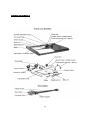
CONTENTS CONTENTS PRODUCT SPECIFICATIONS SAFETY INSTRUCTIOS OPERATION SERVICE AND MAINTENANCE PARTS LIST – DELUXE SLASHER 1 2 2 8 9 12 [1] PRODUCT SPECIFICATIONS Product No. STANDARD SLASHER MODELS SL-1300 L SL-1500 S PTO driven 4ft ~ adjustable reversible skids ~ 40 hp gear box PTO driven 5ft ~ adjustable reversible skids ~ 60 hp gear box DELUX SLASHER MODELS SL-1200 H SL-1500 W SL-1800W PTO driven 4ft ~ adjustable reversible skids ~ 40 hp gear box ~ rear wheel kit PTO driven 5ft ~ adjustable reversible skids ~ 60 hp gear box ~ rear wheel kit PTO driven 6FT ~ adjustable reversible skids ~ 60 hp gear box ~ rear wheel kit, 2 X rear wheel kit Implement Specifications MODELS SL-1200H SL-1500W SL-1300L SL-1500S SL-1800W Tractor HP 25-30hp 25-45hp 25-45hp 40-70hp 50-80hp 3-point linkage Cat-1 Cat-1 Cat-1 Cat-1 Cat-1 Length (excl. wheels) 1385mm 1680mm 1385mm 1680mm 1980mm Width 1290mm 1615mm 1300mm 1500mm 1390mm Height 900mm 900mm 25-100mm 25-100mm 900mm Weight 290kg 384kg 180kg 340kg 548kg Cutting Width 1200mm 1520mm 1300mm 1500mm 1780mm Cutting Height 45,90,135mm 45,90,135mm 25,50,75,100mm 25,50,,75,100mm 45, 90 & 135mm Deck Thickness 4mm 5mm 3.0mm 5.0mm 6mm Wheel Kit Yes-Single Yes-Single No No Yes-Dual Side Wall (Thickness) 10mm 10mm 10mm 10mm 10mm Skids (Thickness) 10mm 10mm 10mm 10mm 10mm Gearbox 40hp 40hp 45hp 65hp 75HP Offsetable (left/Right) Yes Yes No No Yes The Standard Slasher are PTO powered with four available model sizes, in category I three point linkage, from 1.2m to1.8m with gearbox for up to 75 hp. Uses: Perfect around open grassy area ~ slashing a variety of grasses, small trees and light scrub ~ clearing roadsides ~ creating firebreaks. Features: Easy to use general purpose slasher ~ solid hitch ~ adjustable skids ~ multiple cutting heights ~ stone guard ~ 40 or 75hp gearbox models ~ optional rear wheel ~ clean top deck to prevent fire through debris build-up ~ and reduce corrosion ~ off-settable options ~ simple to attach PTO with breakaway clutch. SAFETY INSTRUCTIONS The Deluxe Slasher are PTO powered with available model sizes, in category I and II, three point linkage, from 4ft to 7ft with gearbox for up to 100hp. [2] SAFETY INSTRUCTIONS Uses: Perfect for hobby farms ~ fence-line and wall edge slashing ~ slashing grasses, small trees and light scrub ~ perfect is rough terrain ~ cleaning roadsides ~ creating firebreaks. Features: Built to last medium duty slasher with re-enforced frame ~ quick-release off-set options ~ strength & reliability ~ collapsible hitch ~ adjustable rear wheel allows for tighter turning areas with less stress on both your tractor and the slasher itself ~ thick clean top deck to prevent fire through debris build-up ~ and reduce corrosion ~ simple to attach PTO with breakaway clutch. Before operating the Slasher read the following safety instructions. Failure to comply with these warnings may result in serious injury or death. CONGRATULATIONS! On the purchase of your new Redline Slasher. This information is to assist you in preparing, operating and maintaining your Slasher. Please read and understand the information completely before operating your slasher, paying special attention to all the safety details. Keep this manual handy for a ready reference. 1.1 Safety First YOU are responsible for the SAFE operation and maintenance of your Slasher. YOU must ensure that you and anyone else, who is going to operate, maintain or work around the Slasher is familiar with the operating and maintenance procedures and related SAFETY information contained in this safety practices that should be adhered to while operating the Slasher. Remember, YOU are the key to safety. Good safety practices not only protect you but also the people around you. Make these practices a working part of your safety program. Be certain that EVERYONE operating this equipment is familiar with the recommended operating and maintenance procedures and follows all the safety precautions. Most accidents can be prevented. Do not risk injury by ignoring good safety practices. 1 Slasher owners must give operating instructions to operators or employees before allowing them to operate the machine. 2 The most important safety feature on this equipment is a SAFE operator. It is the operator’s responsibility to read and understand ALL Safety and Operating instructions in the manual and to follow these. All accidents can be avoided. 3 A person who has not read and understood all operating and safety instructions is not qualified to operate the machine. An untrained operator jeopardizes himself and bystanders to possible serious injury or death. 4 Do not modify the equipment in any way. Unauthorized modification may weaken the function and/or safety and could affect the life of the equipment. 5 Think SAFETY! Work SAFETY! 1.2 General Safety 1. Redline Slashers are designed and manufactured only for the purpose of grass or brush cutting. Under no circumstances should they be used for any other purpose. [3] SAFETY INSTRUCTIONS 2. 3. 4. 5. 6. 7. 8. 9. 10. 11. 12. 13. 14. 15. 16. 17. 18. 19. 20. 21. 22. 23. 24. Before using the Slasher, read and ensure you understand the contents of this Safety and Operator’s Manual for the associated implement. Note all the safety instructions. Never allow an improperly trained person, children or anyone who is not familiar with the safety rules and operating instructions to attach or operate the slasher. Before operating the slasher, check all pins, bolts and connections to be sure they are securely in place. Replace any damaged or worn parts immediately. Do not allow unrestrained long hair; lose clothing, or jewelry to be around moving parts. Operating only in daylight or good artificial light. Wear ear protection when operating the slasher. Ensure the P.T.O horse power and three point linkage lifting capacity of the tractor matches the requirements of the slasher, refer to the tractor operators manual for safe working loads, including any counter-weighting that may be required to balance the weight of the slasher. Do not operate the slasher without all the tractor and slasher safety shields in place. Never operate the tractor and slasher until you have read and completely understand the Safety and Operator’s Manual, and each of the Safety Decals attached to the tractor and slasher. Check the gearbox oil level and safety clutch adjustment before using the slasher. Before slashing, clear the area to be cut, of stones, branches or other debris that might be thrown by the slasher, causing injury or damage. Before operating the Slasher inspect the area to be cut to ensure that you are familiar with the ground conditions and in particular any obstacles that may be partially hidden. Keep all people and animals at a safe distance from moving parts and blade thrown debris. Use caution when changing direction on hills. Avoid high speed, steep slopes, sharp turns, sudden breaking and rough terrain. If working under rough conditions with a linkage slasher fitted with a rigid tower, a chain or other flexible top link can be used to allow the slasher to follow the terrain independently of the tractor. Before dismounting from the tractor, or allowing any person to approach the slasher, disengage the P.T.O, switch off the engine, apply the parking brake and ensure the slasher blades have stopped rotating. Never allow any person to ride on the slasher when the machine is operating. Always operate the slasher from the tractor seat. Never clear grass or earth away from the slasher while it is operating. Ensure the tractor engine is switched off and the parking brake is applied before performing any inspection or maintenance on the slasher. Never use alcoholic beverages or drugs which can hinder alertness or coordination while operating this equipment. Consult your doctor about operating this machine while taking prescription medications. Review the safety instructions with all users annually. Ensure maintenance is carried out regularly by a qualified person. Pay particular attention to the P.T.O shaft, safety guards, cutter bar and blades. 1.3 Storage Safety 1. 2. 3. 4. Store the machine in an area away from human activity. Do not permit children to play on or around the stored machine. Store the machine in a dry, level area. Clean grease and oil as required and protect it from the elements. [4] SAFETY INSTRUCTIONS 1.4 Maintenance Safety 1. 2. 3. 4. 5. 6. 7. 8. 9. 10. 11. 12. 13. Good maintenance is your responsibility. Poor maintenance is an invitation to trouble. Follow good shop practices. Keep service area clean and dry. Be sure electrical outlets and tools are properly grounded. Use adequate light for the job at hand. Make sure there is plenty of ventilation. Never operate the engine in a closed building. The exhaust fumes may cause asphyxiation. Before working on this machine, shut off the engine, set the brakes, and remove the ignition key. Never work under equipment unless it is secured by a mechanical stand. Use personal protection devices such as eye, hand and hearing protectors, when performing any service or maintenance work. Use heavy gloves when handling blades. Only use genuine parts for service and maintenance. A fire extinguisher and first aid kit should be kept readily accessible while performing maintenance on this equipment. Periodically tighten all bolts, nuts and screws and check that all pins are properly installed to ensure unit is in a safe condition. When completing a maintenance or service function, make sure all safety shields and devices are installed before placing machine in service. [5] SAFETY INTRUCTIONS 1.5 Safety & Model Decal The position of safety decals are shown in the illustrations below. Good safety requires that you familiarize yourself with the various safety signs, and increase your SAFETY AWARENESS. [6] SAFETY INSTRUCTIONS [7] OPERATION 2.1 Installation Line up the lower linkage arms with the linkage pins of the slasher, slide the linkage arms onto the pins and secure with a lynch pin. Attach the top link to the slasher. Raise the slasher from the ground and adjust the stabilizer bars or chains to allow minimal sideways movement. To disconnect the slasher, lower the slasher to the ground and reverse the above procedure. Check the length of the PTO shaft before connecting it to the tractor by raising the slasher to a position where the shaft would be horizontal when connected. If the shaft is too long it will need to be cut before it is connected. Make sure there is sufficient clearance to allow fitment of the slasher PTO shaft to the tractor PTO stub. PTO Telescoping Shaft Measurements PTO clearance: Attach the slasher to the tractor leaving the PTO shaft detached. Raise the slasher so that the gear box input shaft is level with the tractors PTO output stub. This gives the shortest distance between the tractor PTO output stub and slasher input stub. The telescoping PTO shaft needs to be able to close shorter than this distance by at least 30-50mm measured between the PTO lock out pin and lock out pin groove on the tractors output stub. This ensures the PTO shaft cannot ‘bottom out’ causing damage to the tractor or implement. PTO drive overlap: Lower the slasher to the ground in an operating position. Slide the PTO telescoping shaft apart and attach the coupling ends to the appropriate input and output stub. Ensure the lockout pins are engaged. Hold the unattached shaft ends parallel together. Ensure there is at least 100-150mm overlap (the more the better) of the two metal shafts. Clean and grease the shafts and slide them back together. If you are in any doubt as to any of the above, call your place of purchase. Connecting the PTO Shaft: Better attaching the PTO shaft to the tractor, ensure it is the correct length; not too long or too short. Clean and grease the splines on the tractor and slasher PTO stub shafts and install the PTO shaft making sure that the spring loaded locking pins engage in the interference grooves of the stub shafts. Ensure that the PTO shaft guards are secure and operable. Caution: Depending upon the model it may be possible to raise the slasher too high which will cause the PTO shaft to contact the slasher body. Raise the slasher very slowly to check whether this happens and if so set the upper lift limit of the tractor hydraulics to avoid contact. Contact may cause the PTO shaft to bend and require replacement. Do not rely upon your memory to avoid lifting the slasher too high and damaging the PTO shaft. The PTO shaft can be removed from the slasher; the clutch end of the PTO shaft is fixed at the groove on the slasher input shaft with a bolt and nylock nut. The PTO shaft can be removed or fitted to the tractor, by depressing the quick release pin. All slashers are fitted with an adjustable clutch in the PTO driveline. This allows the rotor to slip under heavy load. The clutch is factory set and should not need adjustment under normal use. After prolonged disuse or weathering the slip clutch should be inspected, maintained and adjusted to ensure its correct operation. With the slasher on the ground, adjust the chain top link so the front of the slasher will lift slightly above the rear. Then raise the slasher very slowly, making sure that the PTO drive shaft shield does not hit the front of the slasher. If it does, damage will be done to the drive shaft shield and, if it hits enough, it will also damage the drive shaft itself, making replacement necessary. [8] OPERATION 2.2 General Operation The Cutting Height Adjustment: The cutting height can be set by lifting the slasher, undoing the bolts and nuts attaching the adjustable skids and repositioning the skid plates to the required height. When adjusting the skids, ensure the whole wear surface touches the ground to avoid uneven wear. Achieve this by adjusting the skids retighten the attaching bolts and nuts securely. Caution: Disengage the PTO, stop the tractor engine and support the slasher on stands before adjusting the skit height. Under heavy cutting conditions it is advantageous to set the rear of the slasher about 25mm higher than the front. This ensures that the material will only be cut once. If the slasher is low at the rear the material will be cut a second time by the rear arc of the blades and will require considerable more power. The Slasher Operation: Before starting to slash, check the area to be cleared to ensure that you are familiar with the ground conditions and that there are no dangerous hazards. This is especially important on land that has not been cut before, such as vacant blocks, sides of roads, channels and drains that can hold hazardous surprises. Dual Clutch: Once all the safety procedures have been followed, start the tractor and raise the slasher approximately 200mm (6 inches) above the ground and engage the PTO at low engine speed. Slowly build up engine revs to give 540 rpm at the PTO and edge slowly forward while lowering the slasher. To minimize wear and tear on both tractor and slasher, the PTO speed should be maintained at 540 rpm. Lower speeds cause excessive wear, especially to blades and bolts, as the lower centrifugal force allows the blades to move on the bolts continuously. Single Clutch: Tractors fitted with a single stage clutch will need an over-run clutch fitted in the PTO drive train. The slasher and tractor will be moving at the same time. Once all safety procedures have been followed, start the tractor and raise the slasher approximately 200mm (6 inches) above the ground. Select the appropriate transmission gear and engage the 540 rpm PTO speed. Release the clutch and increase the engine revs to achieve 540 rpm at the PTO speed. Lower the slasher onto its skids to begin slashing. To minimize wear and tear on both tractor and slasher, The PTO speed should be maintained at 540 rpm. Lower speeds cause excessive wear, especially to blades and bolts, as the lower centrifugal force allows the blades to move the bolts continuously. If the slashing is very heavy and the tractor has difficulty handling it, take a narrower cut, which requires less power. Stopping: Slow engine speed to idle and disengage the PTO shaft. Lower the slasher, switch off the tractor engine and apply the parking brake. SERVICE AND MAINTENANCE 3.1 Service 3.1.1 FLUIDS AND LUBRICANTS 1. Grease: Use multi-purpose lithium based grease. [9] SERVICE AND MAINTENANCE 2. 3. Gear Box Oil: Use SAE 90 Gear oil: Storing Lubricants: Your machine can operate at top efficiency only if clean lubricants are used. Use clean containers to handle all lubricants. Store them in an area protected from dust, moisture and other contaminants. 3.1.2 1. 2. 3. 4. GREASING Use a hand-held grease gun for all greasing. Wipe grease nipple with a clean cloth before greasing, to avoid injecting dirt and grit. Replace and repair broken nipples immediately. If nipples will not take grease, remove and clean thoroughly. Also clean lubricant passageway. Replace nipple if necessary. 3.2 Maintenance The recommended period is based on normal operating conditions. Severe or unusual conditions may require more frequent maintenance. 3.2.1 8 HOURS OR DAILY MAINTENANCE 1. 2. 3. 4. Check and screw all nuts and bolts in connection parts. Check the oil in gearbox. Fill up to line if it’s necessary. Pump grease into each grease nipple three to five times. Clean the implement; take away all grass and mud. 3.2.2 1. 2. 3. 4. 3.2.3 1. 2. 3. 4. 5. SEASON MAINTENANCE Check the machine as above for daily maintenance. Check the oil in gearbox; replace it if it’s contaminated. Check the bearings of blade spindles for wear and tear. If warn, disassemble, clean and replace them if it is necessary, grease as required. Check the distance between bearings and gears. Adjust them if it’s necessary. ANNUAL MAINTENANCE Thoroughly clean the Slasher of mud and grass. Drain the gearbox and clean it thoroughly. Fill with new gear oil up to the indicated oil level. Check and clean blade axles. Replace oil seals and grease them. Check all blades, replace them if they are warn out or damaged. Remove the drive shaft from the machine. Pull the PTO shaft apart. Check and replace any components that are damaged or worn. Install the PTO shaft on the machine. The PTO shaft should telescope easily and the guard turn freely on the shaft [10] SERVICE AND MAINTENANCE 8hrs/Daily Lubricate PTO Shaft Lubricate jockey Wheels Lubricate Blade Spindle x x x Check Gear Box Oil Level x x x Annually x x x x Clean Machine Lubricate and PTO Shaft Cover 3.2.4 40hrs/Weekly x x x PTO SHAFT MAINTENANCE The PTO shaft is designed to telescope to allow for dimensional changes as the machine goes through its operating range. A tubular guard encloses the driving components and is designed to remain stationery on a turning shaft when required. The shaft should telescope easily and the guard turn freely on the shaft at all times. Annual disassembly, cleaning and lubrication is recommended to ensure that all components function as intended. To maintain the shaft, follow this procedure: 1. Remove the shaft from the machine. 2. Pull shaft apart. 3. Use a screwdriver to pry the tabs out of the sleeves on each end. There are 3 tabs per guard. 4. Pull the shaft out of the plastic tubular guard. 5. Use a solvent to clean the male and female portions of the telescoping edge. 6. Apply a light coat of grease to each end. 7. Clean grooves on each end where the tabs are located. Clean each tab also. 8. Apply a light coat of grease to each groove. 9. Insert the shaft into its respective guard and align the slots with the groove. 10. Insert the tabs through the slots and seat in the grove. 11. Check that each guard turns freely on the shaft. 12. Assemble the shaft. 13. Check that the shaft telescopes easily. 14. Replace any components that are damaged or worn. 15. Install the shaft on the machine. 3.2.5 GEARBOX MAINTENANCE The gearbox used on the Slasher will give many years of trouble-free service with minimal maintenance requirements. Maintain the gearbox by following this procedure: Oil level: Remove the level plug from the rear or side of the gearbox. Add oil through the filler plug located on top of gearbox until oil comes out of level plug. Add through the fill plug if required. If gearbox has a dipstick on filler plug, then fill to indicator mark. IMPORTANT: Check the oil level only when the unit is cold and the machine is on the level. [11] SERVICE AND MAINTENANCE 3.3 STORAGE After the season’s use, the machine should be thoroughly inspected and prepared for storage. Repair or replace any worn or damaged components to prevent any unnecessary down time at the start of next season. To ensure a long, trouble free life, follow the procedure outlined below: 1. Thoroughly wash the machine using a pressure washer to remove all dirt, mud, debris and residue. 2. Inspect the blades and rotor for damage or entangled material. Repair or replace damaged parts. Remove all entangled material. 3. Lubricate all grease nipples. Make sure that all grease cavities have been filled with grease to remove any water residue from the inside. 4. Touch up all paint nicks and scratches to prevent rusting. 5. Move to storage area. 6. Select an area that is dry, level and free of debris. 7. Unhook from tractor (see Section 2.4). 8. If the machine cannot be placed inside, cover with a waterproof tarpaulin and tie securely in place Store the machine in an area away from human activity. Do not allow children to play on or around the stored machine. PARTS LIST – Deluxe Slasher [12] PARTS LIST – Deluxe Slasher Deluxe Slasher Assembly parts No 1 2 3 4 5 6 7 8 9 10 11 12 13 14 15 16 17 18 19 20 21 22 23 24 25 26 27 28 29 30 31 32 33 34 Name & Specifications Wheel assembly Pin R pin Locking nut M16 Plain washer 16 Bolt M16x45 Gearbox Clutch Guard Swivel Pin Split pin 2. 5x25 Head Stock Stay Chain Link pin Lynch pin Top link pin Head Stock Deck weldment Bolt M20x70 Blade Boss Blade Carrier Plane washer 20 Locking nut M20 Bolt Blade Locking nut M18 Spring lock washer 16 Adjustable Skids Connecting plate for chain Locking nut M12 Plain washer 12 Bolt M12x30 Chain Guard Bolt M12x45 Adjustable Wheel Mount Pin SL-1300L ― SL1500S Qty 1 2 4 4 4 4 1 1 2 2 optional 2 2 1 1 1 2 1 1 8 4 2 2 2 4 2 2 11 22 5 1 6 1 2 SL1300L Part NO. TM-AZW.HM4FT ZL-25.105 ZL-25.106 GB 6184-86 GB 97.1-85 GB 5783-86 XH30.192Z.01L SL140.00.023 SL140.00.112 GB 91-86 HM4FT.00.211 RB-00.102 200.56.011 EF100.00.019 HM5FT.00.014 HM4FT.00.011 GB 5782-86 HM4FT.00.015 HM4FT.00.210 GB 97.1-85 GB 6184-86 SL140.00.107A SL140.00.108A GB 6184-86 GB 93-87 HM4FT.00.012 HM5FT.00.205 GB 6184-86 GB 97.1-85 GB 5783-86 HM4FT.00.013 GB5783-86 HM5FT.00.018 ZL-25.105 [13] SL1500S Part NO. TM-AZW.001L ZL-25.105 ZL-25.106 GB 6184-86 GB 97.1-85 GB 5783-86 XH30.192Z.01L SL140.00.023 SL140.00.112 GB 91-86 HM4FT6.00.211 RB-00.102 200.56.011 EF100.00.019 HM5FT.00.014 HM4FT6.00.011 GB 5782-86 HM4FT6.00.015 HM4FT6.00.210 GB 97.1-85 GB 6184-86 SL140.00.107A SL140.00.108A GB 6184-86 GB 93-87 HM4FT6.00.012 HM5FT.00.205 GB 6184-86 GB 97.1-85 GB 5783-86 HM4FT6.00.013 GB5783-86 HM5FT.00.018 ZL-25.105 PARTS LIST – Deluxe Slasher Deluxe Slasher Assembly parts No 1 2 3 4 5 6 7 8 9 10 11 12 13 14 15 16 17 18 19 20 21 22 23 24 25 26 27 28 29 30 31 32 33 34 Name & Specifications Wheel assembly Pin R pin Locking nut M16 Plain washer 16 Bolt M16x45 Gearbox Clutch Guard Swivel Pin Split pin 2. 5x25 Head Stock Stay Chain Link pin Lynch pin Top link pin Head Stock Deck weldment Bolt M20x70 Blade Boss Blade Carrier Plane washer 20 Locking nut M20 Bolt Blade Locking nut M18 Spring lock washer 16 Adjustable Skids Connecting plate for chain Locking nut M12 Plain washer 12 Bolt M12x30 Chain Guard Bolt M12x45 Adjustable Wheel Mount Pin SL1200H – SL1800W Qty 1 2 4 4 4 4 1 1 2 2 optional 2 2 1 1 1 2 1 1 8 4 2 2 2 4 2 2 11 22 5 1 6 1 2 SL1200H Part NO. TM-AZW.001L ZL-25.105 ZL-25.106 GB 6184-86 GB 97.1-85 GB 5783-86 XH30.192Z.01L SL140.00.023 SL140.00.112 GB 91-86 HM5FT6.00.211 RB-00.102 200.56.011 EF100.00.019 HM5FT.00.014 HM5FT6.00.011 GB 5782-86 HM5FT6.00.015 HM5FT6.00.210 GB 97.1-85 GB 6184-86 SL140.00.107A SL140.00.108A GB 6184-86 GB 93-87 HM3FT6.00.012 HM5FT.00.205 GB 6184-86 GB 97.1-85 GB 5783-86 HM5FT6.00.013 GB5783-86 HM5FT.00.018 ZL-25.105 [14] SL1500W Part NO. TM-AZW.HM6FT ZL-25.105 ZL-25.106 GB 6184-86 GB 97.1-85 GB 5783-86 XH50.192Z.01L SL140.00.023 SL140.00.112 GB 91-86 HM6FT.00.211 HM6FT.00.204 200.56.011 HM6FT.00.203 HM6FT.00.014 HM6FT.00.011 GB 5782-86 HM6FT.00.015 HM6FT.00.210 GB 97.1-85 GB 6184-86 HM7FT.00.202 HM7FT.00.201 GB 6184-86 GB 93-87 HM6FT.00.012 HM7FT.00.213 GB 6184-86 GB 97.1-85 GB 5783-86 HM6FT.00.013 GB5783-86 HM6FT.00.018 HM6FT.00.205 SL1800W Part NO. TM-AZW.HM6FT ZL-25.105 ZL-25.106 GB 6184-86 GB 97.1-85 GB 5783-86 U100.002 HM7FT.00.023 SL140.00.112 GB 91-86 HM7FT6.00.211 HM6FT.00.204 200.56.011 HM6FT.00.203 HM7FT.00.014 HM7FT6.00.011 GB 5782-86 HM7FT6.00.015 HM7FT6.00.210 GB 97.1-85 GB 6184-86 HM7FT.00.202 HM7FT.00.201 GB 6184-86 GB 93-87 HM7FT6.00.012 HM7FT.00.213 GB 6184-86 GB 97.1-85 GB 5783-86 HM6FT6.00.013 GB5783-86 HM6FT.00.018 HM6FT.00.205 PARTS LIST – Deluxe Slasher Wheelkit Assembly parts Wheel Kit Assembly parts No 1 2 3 4 5 6 7 8 9 10 11 12 13 14 15 16 17 18 Name & Specifications Wheel bracket weldment Wheel fork lock ring Nut M12 Bolt M12x45 Wheel fork Locking nut M16 Plain washer 16 Dust cap Oil seal seat Oil seal W25x40x5 Bearing 6203 Bolt M10x30 Boss hub nave Wheel rim Axle Type Spring lock washer 10 Nut M10 SL1200H – SL1800W Qty 1 1 1 1 1 2 2 2 2 4 2 4 1 2 1 1 4 4 SL1200H Part NO. HM3FT6.00.017 HM5FT.00.208 GB 6170-86 GB 5783-86 HM5FT.00.019 GB 6184-86 GB 97.1-85 12.32.106 12.32.105-1 HG4-692-76 GB/T276-1994 GB 5783-86 12.32.103 12.32.101 TM-AZW.101 HM5FT.01.023 GB 93-87 GB 6170-86 [15] SL1500W Part NO. HM4FT.00.017 HM5FT.00.208 GB 6170-86 GB 5783-86 HM5FT.00.019 GB 6184-86 GB 97.1-85 12.32.106 12.32.105-1 HG4-692-76 GB/T276-1994 GB 5783-86 12.32.103 12.32.101 TM-AZW.101 HM5FT.01.023 GB 93-87 GB 6170-86 SL1800W Part NO. HM5FT.00.017 HM5FT.00.208 GB 6170-86 GB 5783-86 HM5FT.00.019 GB 6184-86 GB 97.1-85 12.32.106 12.32.105-1 HG4-692-76 GB/T276-1994 GB 5783-86 12.32.103 12.32.101 TM-AZW.101 HM5FT.01.023 GB 93-87 GB 6170-86 PARTS LIST – Deluxe Slasher Wheel Kit Assembly parts No 1 2 3 4 5 6 7 8 9 10 11 12 13 14 15 16 17 18 Name & Specifications Wheel bracket weldment Wheel fork lock ring Nut M12 Bolt M12x45 Wheel fork Locking nut M16 Plain washer 16 Dust cap Oil seal seat Oil seal W25x40x5 Bearing 6203 Bolt M10x30 Boss hub nave Wheel rim Axle Type Spring lock washer 10 Nut M10 SL1200H – SL1800W Qty 1 2 3 4 5 6 7 8 9 10 11 12 13 14 15 16 17 18 SL1200H Part NO. HM5FT.00.017 HM5FT.00.208 GB 6170-86 GB 5783-86 HM5FT.00.019 GB 6184-86 GB 97.1-85 12.32.106 12.32.105-1 HG4-692-76 GB/T276-1994 GB 5783-86 12.32.103 12.32.101 TM-AZW.101 HM5FT.01.023 GB 93-87 GB 6170-86 [16] SL1500W Part NO. HM6FT.00.017 HM5FT.00.208 GB 6170-86 GB 5783-86 HM5FT.00.019 GB 6184-86 GB 97.1-85 12.32.106 12.32.105-1 HG4-692-76 GB/T276-1994 GB 5783-86 12.32.103 12.32.101 TM-AZW.101 HM5FT.01.023 GB 93-87 GB 6170-86 SL1800W Part NO. HM6FT.00.017 HM5FT.00.208 GB 6170-86 GB 5783-86 HM5FT.00.019 GB 6184-86 GB 97.1-85 12.32.106 12.32.105-1 HG4-692-76 GB/T276-1994 GB 5783-86 12.32.103 12.32.101 TM-AZW.101 HM5FT.01.023 GB 93-87 GB 6170-86