1
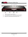
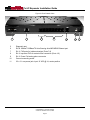
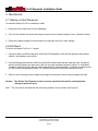
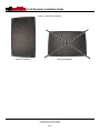
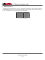
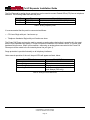
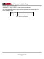
Allworx Px 6/2 Expander Installation Guide No part of this publication may be reproduced, stored in a retrieval system, or transmitted, in any form or by any means, electronic, mechanical, photocopy, recording, or otherwise without the prior written permission of Allworx. © 2008 Allworx, a wholly owned subsidiary of PAETEC. All rights reserved. Allworx is a registered trademark of Allworx Corp. All other names may be trademarks or registered trademarks of their respective owners. Px 6/2 Expander Installation Guide Table of Contents Installation Overview .................................................................................................................................. 1 Unpacking .................................................................................................................................................. 2 Chassis Views............................................................................................................................................ 3 Mechanical ................................................................................................................................................. 5 4.1 Tabletop or Shelf Placement .................................................................................................................... 5 4.2 Wall Mount ............................................................................................................................................... 5 5 Electrical .................................................................................................................................................... 7 5.1 Chassis Ground ....................................................................................................................................... 7 5.2 Power-Up Sequence ................................................................................................................................ 7 6 Diagnostic Port........................................................................................................................................... 8 7 Procuring and Installing the Internet Call Access Feature Key.................................................................... 9 8 Port Expander Configuration .................................................................................................................... 10 8.1 Local Connection ................................................................................................................................... 10 8.1.1 Allworx server is Site’s DHCP server ............................................................................................... 10 8.1.2 Site using non-Allworx DHCP server ............................................................................................... 11 8.2 Remote Connection ............................................................................................................................... 12 8.3 Configuring the Port Expander Password............................................................................................... 13 9 Telephone Line Connection...................................................................................................................... 13 10 Data Network Connection......................................................................................................................... 15 11 Physical and Environmental Specifications............................................................................................... 16 12 Regulatory Notices ................................................................................................................................... 17 12.1 FCC Part 68 ......................................................................................................................................... 17 12.2 Industry Canada................................................................................................................................... 17 12.3 Radio and Television Interference........................................................................................................ 18 13 Wall Mount Template ............................................................................................................................... 20 1 2 3 4 300 Main Street • East Rochester, NY 14445 • Toll Free 1-866-ALLWORX • 585-421-3850 • www.allworx.com © 2008 Allworx. All rights reserved Version 04. Revised: June 2, 2008 Page i Px 6/2 Expander Installation Guide 1 Installation Overview Note: Use of the Allworx Px 6/2 Expander requires connection to an Allworx 6x, 10x, or 24x server. The server must be equipped with the Internet Call Access Feature Key. Procure the key before beginning installation at the customer site. Steps for procuring the key are included in Section 7, Procuring and Installing the Internet Call Access Feature Key. Installation of the Allworx Px 6/2 Expander involves the following steps: 1. Unpacking 2. Mechanical Installation 3. Electrical Installation 4. Procuring and Installing the Internet Call Access Feature Key on the Allworx server. 5. Port Expander Configuration 6. Telephone Line Connection 7. Network Connection Each of these steps will be described in the following sections. 300 Main Street • East Rochester, NY 14445 • Toll Free 1-866-ALLWORX • 585-421-3850 • www.allworx.com © 2008 Allworx. All rights reserved Version 04. Revised: June 2, 2008 Page 1 Px 6/2 Expander Installation Guide 2 Unpacking Open the box and carefully unpack it. Save all shipping and packaging materials. Verify all items against the parts list shown in Table 1. If any items are missing, contact your dealer or Allworx Customer Support at 866255-9679. Quantity 1 1 1 1 Item Allworx Px 6/2 Expander Power Adapter (12 VDC @ 1A) Px 6/2 Expander Installation Guide Sheet of 4 Rubber Feet Table 1: Parts List 300 Main Street • East Rochester, NY 14445 • Toll Free 1-866-ALLWORX • 585-421-3850 • www.allworx.com © 2008 Allworx. All rights reserved Version 04. Revised: June 2, 2008 Page 2 Px 6/2 Expander Installation Guide 3 Chassis Views Figure 1: Front Chassis View 1 2 3 4 1 Power LED – Indicates system start-up activity 2 3 Outside Analog Phone Line LEDs – Indicates status of a particular FXO port Inside Analog Extension LEDs – Indicates status of a particular FXS port 4 Network LED – Indicates Ethernet link status; flashes for activity 300 Main Street • East Rochester, NY 14445 • Toll Free 1-866-ALLWORX • 585-421-3850 • www.allworx.com © 2008 Allworx. All rights reserved Version 04. Revised: June 2, 2008 Page 3 Px 6/2 Expander Installation Guide Figure 2: Rear Chassis View 5 6 7 8 9 5 Diagnostic port 6 7 RJ-45 10BaseT/100BaseTX Auto-Sensing Auto-MDI/MDIX Ethernet port. RJ-11 FXS ports for inside extensions (Ports 7-8) 8 RJ-11 loop-start FXO for central office connection (Ports 1-6) 9 RJ-11 Power Fail analog phone connector 10 11 Ground connecting screw 5.5 x 2.1 mm power jack. Input 12 VDC @ 1A, center positive 300 Main Street • East Rochester, NY 14445 • Toll Free 1-866-ALLWORX • 585-421-3850 • www.allworx.com © 2008 Allworx. All rights reserved Version 04. Revised: June 2, 2008 Page 4 10 11 Px 6/2 Expander Installation Guide 4 Mechanical 4.1 Tabletop or Shelf Placement To install the Allworx Px 6/2 on a tabletop or shelf: 1. Remove the four rubber feet from the packaging. 2. Turn over the chassis and notice the triangle on each corner (2 large triangles in front, 2 smaller in back). 3. Remove the paper backing from each rubber foot and place one foot in each triangle. 4.2 Wall Mount To mount the Allworx Px 6/2 on ½” drywall: 1. Verify that there is sufficient clearance around the Port Expander’s front and rear panels to allow power, network, and telephony connections. 2. Use self-drilling drywall anchors rated for at least 20 lbs with screws that are either #6 or #8. Locate two anchors that will support the upper end of the unit using the template included in Section 13, Wall Mount Template. Install the anchors per the anchor manufacturer’s recommendation. Install the mounting screws into the anchors leaving approximately 1/8” between the bottom of the screw head and the wall. 3. Slide unit onto mounting screws. Adjust screw height if necessary to insure a snug fit against the wall. Caution: The Allworx Port Expander must be securely mounted to the wall to avoid equipment damage or personal injury. Note: The unit must be mounted with the front facing forward, not up or down (see Figure 3). 300 Main Street • East Rochester, NY 14445 • Toll Free 1-866-ALLWORX • 585-421-3850 • www.allworx.com © 2008 Allworx. All rights reserved Version 04. Revised: June 2, 2008 Page 5 Px 6/2 Expander Installation Guide Figure 3: Wall Mount Orientation Correct Orientation Wrong Orientation 300 Main Street • East Rochester, NY 14445 • Toll Free 1-866-ALLWORX • 585-421-3850 • www.allworx.com © 2008 Allworx. All rights reserved Version 04. Revised: June 2, 2008 Page 6 Px 6/2 Expander Installation Guide 5 Electrical 5.1 Chassis Ground Warning: Failure to follow these steps may result in equipment damage, personal injury, and void the product warranty. To help prevent electrical shock, the separate, protective earthing terminal located next to the power jack on the rear panel (See Figure 2 item 10) must be permanently connected to earth using 18 AWG wire or larger. 5.2 Power-Up Sequence Connect the unit’s Network port to an Allworx server LAN. Then connect the AC power adapter. The Port Expander will automatically begin to power up. As it progresses through the power up sequence, the front panel Power LED will flash green. If a network connection has been made and when the unit is ready, the Power LED will shine steady green. If no network connection has been made prior to when the unit is powered on, the Power LED will change from flashing green to solid amber. Solid amber indicates that the unit is in Configuration Mode. 300 Main Street • East Rochester, NY 14445 • Toll Free 1-866-ALLWORX • 585-421-3850 • www.allworx.com © 2008 Allworx. All rights reserved Version 04. Revised: June 2, 2008 Page 7 Px 6/2 Expander Installation Guide 6 Diagnostic Port The Diagnostic connector (See Figure 2, Item 5) is a serial port. Should Allworx Customer Support instruct you to capture diagnostic data, connect a null modem serial cable from the Diagnostic connector to the serial port on a PC. Configure the PC port in accordance with the following table: Baud Data Bits Parity Stop Bits Flow Control 9600 8 None 1 None Table 2: Serial Port Configuration 300 Main Street • East Rochester, NY 14445 • Toll Free 1-866-ALLWORX • 585-421-3850 • www.allworx.com © 2008 Allworx. All rights reserved Version 04. Revised: June 2, 2008 Page 8 Px 6/2 Expander Installation Guide 7 Procuring and Installing the Internet Call Access Feature Key Note: Use of the Allworx Px 6/2 Expander requires connection to an Allworx 6x, 10x, or 24x server. The server must be running Release 6.9 or higher and must have the Internet Call Access Feature Key. Obtain the key using the following procedure: 1. Update the server to Release 6.9 or higher, if it has not already been upgraded. 2. Submit a request for the Internet Call Access key. The Internet Call Access Key must be ordered via the Allworx Reseller Portal in a request form located in the “Reseller Programs” drop down menu. Complete all fields and click Submit. 3. You will receive an email confirmation of your order. After processing the request, Allworx Customer Care will send you another email that contains the Internet Call Access Key. 4. Install the key on the server. If the server has access to the Internet, on the server Admin Maintenance / Feature Keys page, click the Install button. If the server does not have access to the Internet, copy the key from the email and paste it into the Key field on the server Admin Maintenance / Feature Keys page. 300 Main Street • East Rochester, NY 14445 • Toll Free 1-866-ALLWORX • 585-421-3850 • www.allworx.com © 2008 Allworx. All rights reserved Version 04. Revised: June 2, 2008 Page 9 Px 6/2 Expander Installation Guide 8 Port Expander Configuration Much like an Allworx phone, the Port Expander gets its configuration information and software updates from the Allworx server. Therefore, the Network port of the Allworx Px 6/2 Expander must be attached either directly or remotely to an Allworx server. This is usually done by connecting to the server LAN through a network switch. Up to three Port Expanders can be connected to a given server. The diagram below depicts three Port Expanders connected on a server LAN. When connected this way, the Port Expanders require no manual configuration steps. Figure 4, Connection Diagram 8.1 Local Connection If the Allworx Px 6/2 Expander is being installed on the same network as the Allworx server, perform one of the procedures in the following sections that apply to the site’s network configuration. 8.1.1Allworx server is Site’s DHCP server If the Allworx server is acting as the site’s DHCP server, no manual steps are required. When properly connected to the server LAN, the Allworx Px 6/2 will be configured automatically. However, to simplify future maintenance of the Px, it is recommended that the password be set in accordance with the procedure in Section 8.3, Configuring the Port Expander Password. To ensure the automatic configuration will be successful, perform the plug and play installation steps in the following order: 1. If the Port Expander has already been powered on, disconnect power. 2. Connect the Network port of the Port Expander to the LAN of the Allworx server per the diagram above using a standard RJ-45 category 5 Ethernet cable. 3. Apply power to the Port Expander. 4. Observe the Power LED. During power up, it will flash green. When the LED stops flashing and shines solid green, the Port Expander has received any software updates and has been configured. This may 300 Main Street • East Rochester, NY 14445 • Toll Free 1-866-ALLWORX • 585-421-3850 • www.allworx.com © 2008 Allworx. All rights reserved Version 04. Revised: June 2, 2008 Page 10 Px 6/2 Expander Installation Guide take as long as five (5) minutes. It is now ready for CO lines and analog phones to be connected to its FXO and FXS ports. 5. If the Power LED does not shine solid green within five (5) minutes. Unplug the Port Expander’s power adapter, wait five seconds, then plug it back in. 6. Activate the FXO and FXS ports through the Web Admin page on the Allworx Server. Refer to the Allworx System Administrator’s Guide, Release 6.9.2.1 or higher for information on configuring the ports. 8.1.2Site using non-Allworx DHCP server If a device other than the site’s Allworx server is being used as the network’s DHCP server, the Px must either have its Boot Server IP Address set manually or it must get the information from the DHCP server. If the DHCP server supports DHCP Option 66, then the Px will get its Boot Server IP Address from the TFTP Server IP Address value in the DHCP server’s database. Within the DHCP server’s configuration, set the TFTP Server IP Address to be the same as the LAN IP Address of the Allworx server. Then perform a plug and play installation of the Px. If the site’s DHCP server does not support DHCP Option 66, the Px’s network settings must be configured manually. Do this using the following procedure: 1. If the Px has already been powered on, disconnect power. 2. If a cable is plugged into the Network port, disconnect it. 3. Set up the PC’s network interface to obtain an IP address automatically (using DHCP). 4. Apply power to the Px. 5. Wait until the power and port LEDs light solid amber (about 45 seconds). Connect the PC’s network port to the Px’s Network port with a standard RJ-45 category 5 Ethernet cable. 6. Verify that the PC has an IP address on the 192.168.2.xxx network by typing ipconfig /all in a command window on the PC. 7. If the PC did not receive the address, it may be necessary to release and renew the PC’s IP address using the ipconfig command in the command window. 8. Open a web browser on the PC and enter http://192.168.2.254 into the browser’s address field. The Px’s Configuration screen is displayed. 9. Navigate to the Boot Server IP Address field. Enter the IP address of the Allworx Server on which the Px will be installed. 10. Scroll to the New Password field. If it is empty, the Px’s administrator password has not been set. We recommend you create a site-specific password and enter it into the New Password field. Re-enter the password in the Confirm Password field. 11. Click Update. The Px’s Update Result screen is displayed. 12. Click Restart and click OK on the confirmation box. 13. As soon as the Power LED begins flashing, disconnect the Ethernet cable from the Px’s Network port. 14. When the Power LED lights solid amber, disconnect power. 15. Connect the Px to the site’s network then apply power. 300 Main Street • East Rochester, NY 14445 • Toll Free 1-866-ALLWORX • 585-421-3850 • www.allworx.com © 2008 Allworx. All rights reserved Version 04. Revised: June 2, 2008 Page 11 Px 6/2 Expander Installation Guide 8.2 Remote Connection Allworx Px 6/2 Expanders can be configured to run at sites that are remote to the Allworx server. Much like with a remote Allworx phone, this requires manual configuration of the Port Expander. The Boot Server IP (the Allworx Server’s IP) and the server’s Plug and Play Secret Key must be entered within the Port Expander’s configuration interface. In addition, forwarding of ports through intervening firewalls may be required. See the Allworx System Administrator’s Guide, Release 6.9 for instructions for configuring firewalls. Caution: Correct routing of 911 emergency calls for analog handsets attached to remote Allworx Port Expanders cannot be guaranteed. Do not use the Px’s FXS ports for handsets from which placing 911 calls may be attempted. Caution: If the network connection between the Port Expander and the Allworx server is interrupted, regular use of the Port Expander’s FXO and FXS ports will not be possible. The only option for placing calls through a Port Expander that does not have a functional network connection to its Allworx server is to plug an analog phone into the Power Fail port. Calls placed using this phone will be routed to the CO line connected to FXO port 1. No other ports will be functional. To configure the Boot Server IP and Plug and Play Secret Key, perform the following steps: 1. Access the Port Expander’s Configuration screen by performing Steps 1 through 7 of the procedure in Section 8.3, Configuring the Port Expander Password. 2. Navigate to the Boot Server IP Address field. Enter the IP address of the Allworx Server to which the Port Expander will be associated. 3. Navigate to the Plug and Play Secret Key field. Enter the Allworx Server’s Secret Key. To determine the server’s Secret Key, see the Allworx System Administrator’s Guide, Release 6.9 for instructions. 4. Re-enter the key in the Confirm Plug and Play Secret Key field. 5. Scroll to the New Password field. If it is empty, the Px’s administrator password has not been set. We recommend you create a site-specific password and enter it into the New Password field. Re-enter the password in the Confirm Password field. 6. Click Update. The Port Expander’s Update Result screen is displayed. 7. Click Restart 8. Connect the Network port of the Port Expander to the site’s network using a standard RJ-45 category 5 Ethernet cable. Note: A network path to the Allworx Server must be available. 9. Observe the Power LED. During power up, it will flash green. When the LED stops flashing and shines solid green, the Port Expander has received any software updates, and has been fully configured. This may take as long as five (5) minutes. It is now ready for CO lines and analog phones to be connected to its FXO and FXS ports. 10. If the Power LED does not shine solid green within five (5) minutes. Unplug and re-plug the Port Expander’s power adapter. 300 Main Street • East Rochester, NY 14445 • Toll Free 1-866-ALLWORX • 585-421-3850 • www.allworx.com © 2008 Allworx. All rights reserved Version 04. Revised: June 2, 2008 Page 12 Px 6/2 Expander Installation Guide 11. If you have entered a new password, save it for future reference. If the password is lost or forgotten, it can be reset by repeating the procedure in Section 8.3, Configuring the Port Expander Password and entering a new password. 12. Activate the FXO and FXS ports through the Web Admin page on the Allworx Server. Refer to the Allworx System Administrator’s Guide for Release 6.9 or higher for information on configuring the ports. 8.3 Configuring the Port Expander Password Although connecting the Port Expander normally does not require any manual configuration, the need to configure the Port Expander’s settings may arise in the future. Such situations can be made more convenient by setting the Port Expander’s password during installation. For security reasons, Allworx Px 6/2 Expanders do not have a default password. A site-specific password must be created and entered using the Port Expander’s Configuration web page. If you have not already set the password as part of initial setup of the Px, do so using the following procedure: 1. If the Port Expander has already been powered on, disconnect power. 2. If a cable is plugged into the Network port, disconnect it. 3. Set up the PC’s network interface to obtain an IP address automatically (using DHCP). 4. Apply power to the Port Expander. 5. Wait until the power and port LEDs light solid amber (about 45 seconds). Connect the PC’s network port to the Port Expander’s Network port with a standard RJ-45 category 5 Ethernet cable. 6. Verify that the PC has an IP address on the 192.168.2.xxx network. You may need to release and renew the PC’s IP address using the ipconfig command in a command window to get an address from the Port Expander. 7. Open a web browser on the PC and enter http://192.168.2.254 into the browser’s address field. The Port Expander’s Configuration screen is displayed. 8. Scroll to the New Password field. Enter the site’s new Port Expander administrator password. Re-enter the password in the Confirm Password field. The Port Expander’s Configuration screen is displayed. 9. Click Update. The Port Expander’s Update Result screen is displayed. 10. Disconnect the network cable from the Port Expander’s Network port. Connect the Port Expander to the system using the procedure in either Section 8.2, Local Connection or Section12, Remote Connection. 11. Save the password for future reference. If the password is lost or forgotten, it can be reset by repeating this procedure and entering a new password. 9 Telephone Line Connection Caution: To reduce the risk of fire, use only 26 AWG (or larger) UL listed or CSA certified telecommunications line cord. 300 Main Street • East Rochester, NY 14445 • Toll Free 1-866-ALLWORX • 585-421-3850 • www.allworx.com © 2008 Allworx. All rights reserved Version 04. Revised: June 2, 2008 Page 13 Px 6/2 Expander Installation Guide The Port Expander’s analog phone connections can be used to connect Central Office (CO) lines or telephone handsets. The following table describes the ports: RJ-11 Ports Type 1-6 FXO (loop-start) 7-8 FXS Description Used to connect to Central Office (CO) lines Analog telephone handsets Table 3: Analog Telephony Ports It is recommended that the ports be connected as follows: • CO Lines: Begin with port 1 and move up. • Telephone Handsets: Begin with port 8 and move down. The Power Fail Phone port may be used to connect an analog phone device that is operational in the event that the Port Expander loses power, if it loses its network connection to the Allworx server, or if some other hardware failure occurs. When in this condition, calls using an analog phone connected to the Power Fail Phone port will be routed to the first outside phone line port (port 1). Surge protection is provided internally on all telephony interfaces. Under normal operation of the unit, the port LEDs will appear as listed, below. Port LED Indicator Off Green Solid Green Fast Blink Alternating Red/Amber Port (1-8) State Normal Idle Off Hook Ringing No loop current detected on last off hook attempt (FXO only) Table 4: Analog Port LED Definitions 300 Main Street • East Rochester, NY 14445 • Toll Free 1-866-ALLWORX • 585-421-3850 • www.allworx.com © 2008 Allworx. All rights reserved Version 04. Revised: June 2, 2008 Page 14 Px 6/2 Expander Installation Guide 10 Data Network Connection The Network port is 10BaseT/100BaseTX auto-sensing and auto-MDI/MDIX port. Once the Port Expander is powered up and in normal mode, the Network LED indicates the state of the Network link, as shown below. Color State Description Off No link: the network is not connected Green On Link: the network is successfully connected Blinking Activity: data is being transmitted or received Table 5: Network Port LED Definitions 300 Main Street • East Rochester, NY 14445 • Toll Free 1-866-ALLWORX • 585-421-3850 • www.allworx.com © 2008 Allworx. All rights reserved Version 04. Revised: June 2, 2008 Page 15 Px 6/2 Expander Installation Guide 11 Physical and Environmental Specifications Dimensions (W x H x D) Weight (Base Model) Power Temperature Humidity 12.1 x 1.9 x 7.6 inches (30.8 x 4.8 x 19.3 cm) 3 lbs DC 12V, 1 Amp. 0° ~ 40° C 15% ~ 90% RH, Non-condensing Table 6: Physical and Environmental Specifications 300 Main Street • East Rochester, NY 14445 • Toll Free 1-866-ALLWORX • 585-421-3850 • www.allworx.com © 2008 Allworx. All rights reserved Version 04. Revised: June 2, 2008 Page 16 Px 6/2 Expander Installation Guide 12 Regulatory Notices 12.1 FCC Part 68 This equipment complies with Part 68 of FCC rules and the requirements adopted by ACTA. On the backside of this equipment is a label that contains, among other information, a product identifier in the format US: AAAEQ##TXXXX. If requested, provide this number to the telephone company. A plug and jack used to connect this equipment to the premises wiring and telephone network must comply with the applicable FCC Part 68 rules and requirements adopted by the ACTA. See installation instructions for details. The REN is used to determine the number of devices that may be connected to a telephone line. Excessive RENs on a telephone line may result in the devices not ringing in response to an incoming call. In most but not all areas, the sum of RENs should not exceed five (5.0). To be certain of the number of devices that may be connected to a line, as determined by the total RENs, contact the local telephone company. For products approved after July 23, 2001, the REN for this product is part of the product identifier that has the format US:AAAEQ##TXXXX. The digits represented by ## are the REN without a decimal point (e.g., 03 is a REN of 0.3). For earlier products, the REN is separately shown on the label. If this equipment causes harm to the telephone network, the telephone company will notify you in advance that temporary discontinuance of service may be required. But if advance notice isn't practical, the telephone company will notify the customer as soon as possible. Also, you will be advised of your right to file a complaint with the FCC if you believe it is necessary. The telephone company may make changes in its facilities, equipment, operations or procedures that could affect the operation of the equipment. If this happens, the telephone company will provide advance notice in order for you to make necessary modifications to maintain uninterrupted service. If trouble is experienced with this equipment, for repair or warranty information, please contact our company. If the equipment is causing harm to the telephone network, the telephone company may request that you disconnect the equipment until the problem is resolved. 12.2 Industry Canada The Industry Canada label identifies certified equipment. This certification means that the equipment meets telecommunications network protective, operation and safety requirements as prescribed in the appropriate Terminal Equipment Technical Requirements document(s). The Department does not guarantee the equipment will operate to the user's satisfaction. Before installing this equipment, users should ensure that it is permissible to be connected to the facilities of the local telecommunications company. The equipment must also be installed using and acceptable method of connection. The customer should be aware that compliance with the above conditions might not prevent degradation of service in some situations. Repairs to certified equipment should be coordinated by a representative designated by the supplier. Any repairs or alterations made by the user to this equipment, or equipment malfunctions, may give the telecommunications company cause to request the user to disconnect the equipment. 300 Main Street • East Rochester, NY 14445 • Toll Free 1-866-ALLWORX • 585-421-3850 • www.allworx.com © 2008 Allworx. All rights reserved Version 04. Revised: June 2, 2008 Page 17 Px 6/2 Expander Installation Guide Users should ensure for their own protection that the electrical ground connections of the power utility, telephone lines and internal metallic water pipe system, if present, are connected together. This precaution may be particularly important in rural areas. Caution: Users should not attempt to make such connections themselves, but should contact the appropriate electric inspection authority, or electrician, as appropriate. NOTICE: This equipment meets the applicable Industry Canada Terminal Equipment Technical Specifications. This is confirmed by the registration number. The abbreviation, IC, before the registration number signifies that registration was performed based on a Declaration of Conformity indicating that Industry Canada technical specifications were met. It does not imply that Industry Canada approved the equipment. AVIS: Le présent matériel est conforme aux spécifications techniques d’Industrie Canada applicables au matériel terminal. Cette conformité est confirmée par le numéro d'enregistrement. Le sigle IC, placé devant le numéro d'enregistrement, signifie que l’enregistrement s’est effectué conformément à une déclaration de conformité et indique que les spécifications techniques d'Industrie Canada ont été respectées. Il n’implique pas qu’Industrie Canada a approuvé le matériel. NOTICE: The Ringer Equivalence Number (REN) for this terminal equipment is 0.1. The REN assigned to each terminal device provides an indication of the maximum number of terminals allowed to be connected to a telephone interface. The termination on an interface may consist of any combination of devices subject only to the requirement that the sum of the Ringer Equivalence Numbers of all the devices does not exceed 5. AVIS : L'indice d'équivalence de la sonnerie (IES) du présent matériel est de 0.1. L'IES assigné à chaque dispositif terminal indique le nombre maximal de terminaux qui peuvent être raccordés à une interface téléphonique. La terminaison d'une interface peut consister en une combinaison quelconque de dispositifs, à la seule condition que la somme d'indices d'équivalence de la sonnerie de tous les dispositifs n'excède pas 5. 12.3 Radio and Television Interference This equipment has been tested and found to comply with the limits for a Class A digital device, pursuant to Part 15 of the FCC rules. These limits are designed to provide reasonable protection against harmful interference in a residential installation. This equipment generates uses and can radiate radio frequency energy and, if not installed and used in accordance with the instructions, may cause harmful interference to radio communications. There is no guarantee, however, that interference will not occur in a particular installation. If this equipment does cause harmful interference to radio or television reception, which can be determined by turning the equipment off and on, the user is encouraged to try to correct the interference by one or more of the following measures: • Reorient or relocate the receiving antenna. • Increase the separation between the equipment and the receiver. • Connect the equipment into an outlet on a circuit different from that to which the receiver is connected. • Consult the dealer or an experienced radio/TV technician for help. 300 Main Street • East Rochester, NY 14445 • Toll Free 1-866-ALLWORX • 585-421-3850 • www.allworx.com © 2008 Allworx. All rights reserved Version 04. Revised: June 2, 2008 Page 18 Px 6/2 Expander Installation Guide You may also find helpful the following booklet, prepared by the FCC: "How to Identify and Resolve Radio-TV Interference Problems.” This booklet is available from the U.S. Government Printing Office, Washington D.C. 20402. Changes and Modifications not expressly approved by the manufacturer or registrant of this equipment can void your authority to operate this equipment under Federal Communications Commissions rules. This digital apparatus does not exceed the Class A limits for radio noise emissions from digital apparatus set out in the Radio Interference Regulations of the Canadian Department of Communications. Le présent appareil numérique n'emet pas de bruits radioélectriques depassant les limites applicables aux appareils numérique de la class A préscrites dans le Règlement sur le brouillage radioélectrique édicte par le Ministere des Communications du Canada. 300 Main Street • East Rochester, NY 14445 • Toll Free 1-866-ALLWORX • 585-421-3850 • www.allworx.com © 2008 Allworx. All rights reserved Version 04. Revised: June 2, 2008 Page 19 Px 6/2 Expander Installation Guide 13 Wall Mount Template 300 Main Street • East Rochester, NY 14445 • Toll Free 1-866-ALLWORX • 585-421-3850 • www.allworx.com © 2008 Allworx. All rights reserved Version 04. Revised: June 2, 2008 Page 20