1
ZOOM HD
Owner/Operator
Manual
Models
991039
991040-
- Zoom 2452 HD
Zoom 2660 HD
03253300A
11/07
Printed in USA
iq-'_:]|=
Eo]J[a_o]_/i;_/_
_]
Safety ...........................
4
Service and Adjustments
Assembly ........................
9
Storage .........................
28
Controls and Features
............
..........
17
11
Accessories
.....................
29
Operation .......................
12
Service Parts ....................
29
Maintenance
16
Specifications
30
Schedule ............
...................
I1_//t_o_o]_l
NON-ENGLISH
MANUALS
THE MANUAL
Manuals in languages other than
,_
English
may your
be obtained
from your
Dealer. Visit
dealer or
www.ariens.com for a list of
[_
anguages available for your
equipment.
Manuals printed in languages other
than English are also available as a
free download on our website:
http://www.ariens.com
Puede obtener manuales en
idiomas diferentes del ingles en su
distribuidor. Visite a su distribuidor
disponibles
para su equipo.
Tambien puede imprimir manuales
en idiomas diferentes del ingles
descargandolos gratuitamente de
nuestra pagina Web:
All reference to left, right, front, or rear are
given from operator sitting in the operation
position and facing the direction of forward
travel.
SERVICE AND REPLACEMENT
PARTS
MANUALES EN IDIOMAS
DIFERENTES DEL INGLES
o vaya a www.ariens.com para
obtener una lista de idiomas
Before operation of unit, carefully and
completely read your manuals. The contents
will provide you with an understanding of
safety instructions and controls during normal
operation and maintenance.
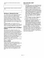
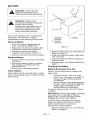
When ordering publications, replacement
parts, or making service inquiries, know the
Model and Serial numbers of your unit and
engine.
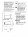
Numbers are located on the product
registration form in the literature package.
They are printed on a serial number label,
located on the frame of your unit (Figure 1).
Serial Number Label
http://www.ariens.com
Manuels non anglais
Des manuels dans differentes
,_
langues
sont disponibles
chez
votre
revendeur.
Rendez-vous
chez votre revendeur ou allez sur
-1
le site www.ariens.com
pour
consulter
la liste des langues
disponibles pour votre equipement.
Les manuels imprimes dans des
langues differentes de I'anglais
sont egalement disponibles en
telechargement gratuit sur notre
site Web :
OF1612
Figure 1
http://www.ariens.com
GB -2
•Record
UnitModel
andSerial
numbers
here.
[
• Record Engine Model and Serial numbers
here.
[
PRODUCT REGISTRATION
The Ariens dealer must register the product
at the time of purchase. Registering the
product will help the company process
warranty claims or contact you with the latest
service information. All claims meeting
requirements during the limited warranty
period will be honored, whether or not the
product registration card is returned. Keep a
proof of purchase if you do not register your
unit.
Customer Note: If the Dealer does not
register your product, please fill out, sign and
return the product registration card to Ariens
or go to www.ariens.com on the internet.
UNAUTHORIZED
PARTS
REPLACEMENT
Use only Ariens replacement parts. The
replacement of any part on this equipment
with anything other than an Ariens authorized
replacement part may adversely affect the
performance, durability, and safety of this unit
and may void the warranty. Ariens disclaims
liability for any claims or damages, whether
regarding warranty, property damage,
personal injury or death arising out of the use
of unauthorized replacement parts.
NOTE: To locate your nearest Ariens Dealer,
go to www.ariens.com.
DISCLAIMER
Ariens reserves the right to discontinue,
change, and improve its products at any time
without public notice or obligation to the
purchaser. The descriptions and
specifications contained in this manual were
in effect at printing. Equipment described
within this manual may be optional. Some
illustrations may not be applicable to your
unit.
GB-3
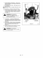
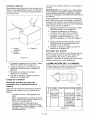
DEALER DELIVERY
Dealer should:
1. Test brakes after unit is assembled to be
sure adjustment has not been disturbed
in shipment (See Parking Brake
Interlock System on page 12). Wheel
brakes are properly adjusted at factory.
2. Check the safety interlock system to
make sure that it is functioning properly.
With operator on seat, unit must not start
unless steering levers are in neutral (N)
and Power Takeoff (PTO) is disengaged
(Off). Engine must stop if operator
leaves seat when steering levers are in
any drive position or PTO is engaged
(On). See Safety Interlock System on
page 12.
3. Fill out Original Purchaser Registration
Card and return the card to Ariens.
4. Explain Limited Warranty Policy.
5. Explain recommended lubrication and
maintenance. Advise customer on
adjustments. Instruct customer on
controls and operation of unit. Discuss
and emphasize the Safety Precautions.
Give customer Owner/Operator, Parts,
and Engine Manuals. Advise customer
to thoroughly read and understand them.
Customer Note: Your Dealer has been
provided complete set-up and preparation
instructions which must be completed prior to
you taking delivery of this unit. The dealer is
required to review important information in
this manual with you before or upon delivery
of the unit or attachment.
_."Y-'_
=1=1i'4
WARNING: This cutting machine
is capable of amputating hands
and feet and throwing objects.
Failure to observe the safety
instructions in the manuals and
on decals could result in serious
injury or death.
Slopes are a major factor related
to loss-of-control and tip-over
accidents. Operation on all slopes
requires extra caution.
Tragic accidents can occur if the
operator is not alert to the
presence of children. Never
assume that children will remain
where you last saw them.
Gasoline is extremely flammable
and the vapors are explosive,
handle with care.
Disengage attachment, stop unit
and engine, remove key, engage
parking brake, and allow moving
parts to stop before leaving
operator's position.
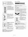
SAFETY ALERT
SYMBOL
0LI253
These are safety alert
symbols. They mean:
,ATTENTION!
•YOUR SAFETY IS
INVOLVED!
When you see this symbol:
•BECOME ALERT7
•OBEY THE MESSAGE!
0L3900
SIGNAL WORDS
The safety alert symbols above and signal
words below are used on decals and in this
manual.
Read and understand all safety messages.
,_
HAZARDOUSPOTENTIALLY
SITUATION! If not
WARNING:
avoided, COULD RESULT in
death or serious injury.
CAUTION: POTENTIALLY
HAZARDOUS SITUATION! If not
avoided, MAY RESULT in minor
or moderate injury. It may also be
used to alert against unsafe
practices.
NOTATIONS
NOTE: General reference information for
proper operation and maintenance practices.
IMPORTANT: Specific procedures or
information required to prevent damage to
unit or attachment.
PRACTICES AND LAWS
Practice usual and customary safe working
precautions, for the benefit of yourself and
others. Understand and follow all safety
messages. Be alert to unsafe conditions and
the possibility of minor, moderate, or serious
injury or death. Learn applicable rules and
laws in your area, including those that may
restrict the age of the operator.
REQUIRED OPERATOR
TRAINING
Original purchaser of this unit was instructed
by the seller on safe and proper operation. If
unit is to be used by someone other than
original purchaser (loaned, rented or sold),
ALWAYS provide this manual and any
needed safety training before operation.
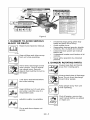
SAFETY DECALS AND
LOCATIONS
ALWAYS replace missing or damaged Safety
Decals. Refer to Figure 2 for Safety Decal
locations.
DANGER: IMMINENTLY
HAZARDOUS SITUATION! If not
avoided, WILL RESULT in death
or serious injury.
GB -4
OF0002
Figure 2
• DANGER! TO AVOID SERIOUS
INJURY OR DEATH
Read Owner/Operator
If machine stops going uphill, stop
blade and back down slowly.
Avoid sudden turns.
Keep safety devices (guards, shields,
switches, etc.) in place and working.
Check interlock system per manual
before use.
Understand location and function of all
controls.
Manual.
OL1801
Keep children and others away
from unit while operating.
Never allow operation by untrained
persons.
2. DANGER! ROTATING PARTS
OL4370
Always keep feet and hands
away from rotating parts.
Never direct discharge toward
other people. Thrown objects
can cause injury. Remove
objects that could be thrown by
the blade.
OL3030
OL0910
Always stand clear of discharge
area. Do not direct discharge
toward other people.
Look down and behind before
and while backing.
OL0910
Keep people away from unit
OL4460
Keep children out of work area
and under watchful care of a
responsible adult.
ID
_1_
I
while operating.
OL3292
--
OL4470
Shut off engine, remove key,
NEVER CARRY CHILDREN.
or repair unit.
read manual before you adjust
OL4010
OL4480GO up and down slopes, not
across.
GB-5
_ _
NOSTEP!
Always
keep
feet
away
fromrotating
parts.
(@,,}
OL4420
3. WARNING!
Do not operate mower unless guards are in
operating position or bagger is attached.
Always stand clear of discharge
area.
OL4430
Do not operate mower unless
bagger is attached or guards
are in operating position.
OL3320
4. HOT SURFACES!
DO NOT touch parts which
are hot from operation.
ALWAYS allow parts to cool.
©S0731
5. ROTATING PARTS
rotating parts.
[_
AVOID INJURY. Stay clear of
OF3450
6. DANGER!
Inspect unit before each use for: missing or
damaged decals and shields, correctly
operating safety interlock system, and
deterioration of grass catchers. Replace or
repair as needed.
ALWAYS check overhead and side
clearances carefully before operation.
ALWAYS be aware of traffic when operating
along streets or curbs.
Keep children and people away.
Keep children out of work area and under
watchful care of a responsible adult.
Keep area of operation clear of all toys, pets,
and debris. Thrown objects can cause injury.
Check for weak spots on docks, ramps or
floors. Avoid uneven work areas and rough
terrain. Stay alert for hidden hazards or traffic.
DO NOT operate near drop-offs, ditches, or
embankments. Unit can suddenly turn over if
a wheel is over the edge of a cliff or ditch, or if
an edge caves in.
Data indicates that operators, age 60 and
above, are involved in a larger percentage of
riding mower related injuries. These
operators should evaluate their ability to
operate the riding mower safely enough to
protect themselves and others from serious
injury.
Read the entire Owner/Operator manual and
other training material. If the operator or the
mechanic cannot read the manual, it is the
owner's responsibility to explain it to them.
Only the user can prevent and is responsible
for accidents or injuries occurring to
themselves, other people or property.
Only trained adults may operate or service
unit. Training includes actual operation.
rotating parts.
AVOID INJURY. Stay clear of
OL4730
SAFETY RULES
Read, understand, and follow all safety
practices in Owner/Operator Manual before
beginning assembly. Failure to follow
instructions could result in personal injury
and!or damage to unit.
ALWAYS remove key and!or wire from spark
plug before assembly. Unintentional engine
start up can cause death or serious injury.
Complete a walk around inspection of unit
and work area to understand:
• Work area • Your unit • All safety decals
Determine which attachments are needed
and can be used safely.
Local regulations may restrict the age of the
operator.
NEVER allow children to operate or play on
or near unit. Be alert and shut off unit if
children enter area.
NEVER operate unit after or during the use of
medication, drugs or alcohol. Safe operation
requires your complete and unimpaired
attention at all times.
DO NOT wear loose clothing or jewelry and
tie back hair that may get caught in rotating
parts.
Wear adequate outer garments.
NEVER wear open sandals or canvas shoes
during operation. Wear adequate safety gear,
protective gloves and footwear.
Wear proper footwear to improve footing on
slippery surfaces.
GB -6
Always
wear
safety
goggles
orsafety
glasses DONOT
mow
onwetgrass.
Reduced
withsideshields
when
operating
mower. traction
could
cause
sliding
andeffect
the
stability.
Moving
parts
cancutoramputate
fingers
ora machine's
hand.
Wrap
blade(s)
orwear
gloves
to
Watch
fortraffic
when
operating
near
or
service.
Onmultiblade
mowers,
rotation
of
crossing
roadways.
oneblade
willcause
allblades
torotate.
Never
carry
passengers.
NEVER
place
yourhands
oranypartofyour DONOT
trytostabilize
themachine
by
body
orclothing
inside
ornear
anymoving putting
yourfootontheground.
partwhile
unitisrunning.
Never
direct
discharge
towards
persons
or
ALWAYS
keep
hands
andfeetaway
from
all property
thatmaybeinjured
ordamaged
by
rotating
parts
during
operation.
Rotating
parts thrown
objects.
Useextreme
caution
on
cancutoffbody
parts.
gravel
surfaces.
ALWAYS
keep
body
andhands
away
from Always
stand
clear
ofthedischarge
area.
pinholes
ornozzles
which
eject
hydraulic ALWAYS
disengage
PTO,
stop
u
nit
a
nd
fluidunder
pressure.
engine,
remove
key,
engage
parking
brake
DONOT
touch
parts
which
arehot.Allow
andallow
moving
parts
tostopbefore
leaving
parts
tocool.
operator's
position.
ALWAYS
keep
hands
andfeetaway
from
all Never
engage
PTO
while
raising
attachment
pinch
points.
orwhen
attachment
isinraised
position.
Fumes
fromtheengine
exhaust
cancause DONOT
operate
attoofastarate.
DONOT
death
orserious
injury.
DONOT
runengine
in change
engine
governor
settings
oroveranenclosed
area.
Always
provide
good
speed
engine.
Slow
down
before
turning.
ventilation.
DONOT
operate
inreverse
unless
absolutely
Read,
understand,
andfollow
allinstructionsnecessary.
ALWAYS
look
d
own
a
nd
behind
inthemanual
andonthemachine
before before
andwhile
backing.
starting.
Understand:
Stopandinspect
equipment
ifyoustrike
an
Howtooperate
allcontrols
object
orifthere
isanunusual
vibration.
Thefunctions
ofallcontrols
Repair,
ifnecessary,
before
restarting.
Never
HowtoSTOP
inanEmergency make
adjustments
orrepairs
withtheengine
Braking
andsteering
characteristicsrunning.
Turning
radius
andclearances
Mower
blades
aresharp
andcancutyou.
theblade(s)
orwear
gloves,
anduse
Keep
safety
devices
orguards
inplace
and Wrap
extra
caution
when
servicing
them.
NEVER
functioning
properly.
NEVER
modify
or
weldorstraighten
mower
blades.
remove
safety
devices.
Rotation
ofoneblade
maycause
rotation
of
Donotoperate
without
either
entire
grass
theother
blades.
catcher
orthedischarge
guard
inplace.
allpossible
precautions
when
leaving
Stop
engine
before
removing
grass
catcher
or Take
unitunattended.
Shut
offengine.
Remove
unclogging
chute.
from
spark
plugandsecure
itaway
from
Ensure
Safety
Interlock
System
isfunctioningwire
spark
plug.
properly.
DONOT
operate
unitifsafety
ALWAYS
remove
keytoprevent
unauthorized
interlock
isdamaged
ordisabled.
use.
Start
andoperate
unitonlywhen
seated
in
operator's
position.
Steering
control
levers Know the weight of loads. Limit loads to those
you can safely control and the unit can safely
must
beinneutral,
PTOdisengaged
and
handle.
parking
brake
setwhen
starting
engine.
Usecare
when
approaching
blind
corners, Disengage PTO when attachment is not in
use. ALWAYS turn off power to attachment
shrubs,
trees
orother
objects
thatmay
obscure
vision.
when travelling, crossing driveways, etc.
Dust,
smoke,
fog,etc.canreduce
vision
and Mow up and down slopes, not across them.
cause
anaccident.
Mow
onlyindaylight
or
Use of a Rollover Protection System (ROPS)
good
artificial
light.
is recommended for slope operation. See
Avoid
slippery
surfaces.
Always
besure
of
Attachments and Accessories.
yourfooting.
GB-7
Always
wear
aseatbeltwhen
operating
unit NEVER fill or drain fuel tank indoors.
using
aRollover
Protection
System
(ROPS). Replace fuel cap securely and clean
Keep
allmovements
ontheslope
slow and
spilled fuel.
gradual. Do not make sudden changes in
speed or direction.
Never fill containers inside a vehicle or on a
Avoid starting or stopping on the slope. If tires
lose traction, disengage the blades and
proceed slowly straight down the slope.
If you cannot back up a slope or you feel
uneasy on it, do not mow it.
DO NOT park on slopes unless necessary.
When parking on slope always chock or block
wheels. Always set parking brake.
Use a slow speed. Tires may lose traction on
slopes even though the brakes are
functioning properly.
Do not bypass transmission
when on a slope.
towed equipment.
On slopes, the weight of the towed equipment
may cause loss of control.
Travel slowly and allow extra distance to stop.
Use extra care when loading or unloading
unit onto trailer or truck.
Secure unit chassis to transport vehicle.
NEVER secure from rods or linkages that
could be damaged.
Keep the nozzle in contact with the rim of the
fuel tank or container opening at all times until
fueling is complete. Do not use a nozzle lockopen device.
Reverse connections may result in sparks
which can cause serious injury. Always
connect positive (+) lead of charger to
positive (+) terminal, and negative (-) lead to
negative (-) terminal.
ALWAYS disconnect negative (-) cable FIRST
and positive (+) cable SECOND. ALWAYS
connect positive (+) cable FIRST, and
negative (-)cable SECOND.
Explosive Gases from battery can cause
death or serious injury. Poisonous battery
fluid contains sulfuric acid and its contact with
DO NOT transport machine while engine is
running.
skin, eyes or clothing can cause severe
chemical burns.
ALWAYS turn off power to attachment and
shut off fuel when transporting unit.
No flames, No sparks, No smoking near
battery.
Keep unit free of debris. Clean up oil or fuel
spills.
This product is equipped with an internal
combustion type engine. DO NOT use unit on
or near any unimproved, forest-covered or
brush covered land unless exhaust system is
equipped with a spark arrester meeting
applicable local, state or federal laws. A spark
arrester, if it is used, must be maintained in
effective working order by operator.
NEVER fill fuel tank when engine is running
or hot from operation.
When practical, remove gas-powered
equipment from the truck or trailer and refuel
it on the ground. If this is not possible, then
refuel such equipment on a trailer with a
portable container, rather than from a
gasoline dispenser nozzle.
Avoid Electric Shock. Objects contacting both
battery terminals at the same time may result
in injury and unit damage. DO NOT reverse
battery connections.
for weight limits for towed equipment and
towing on slopes.
NEVER allow children or others in or on
NO smoking, NO sparks, NO flames.
ALWAYS allow engine to cool before
servicing.
truck or trailer bed with a plastic liner. Always
place containers on the ground away from
your vehicle before filling.
If fuel is spilled on clothing, change clothing
immediately.
Tow only with a machine that has a hitch
designed for towing. Do not attach towed
equipment except at the hitch point.
Follow the manufacturer's recommendations
Fuel is highly flammable and its vapors are
explosive. Handle with care. Use an
approved fuel container.
up
ALWAYS wear safety glasses and protective
gear near battery. Use insulated tools.
DO NOT TIP battery beyond a 45 ° angle in
any direction.
ALWAYS keep batteries out of reach of
children.
Battery posts, terminals and related
accessories contain lead and lead
compounds, chemicals known to the State of
California to cause cancer and reproductive
harm. Wash hands after handling.
ALWAYS block wheels and know all jack
stands are strong and secure and will hold
weight of unit during maintenance.
Release pressure slowly from components
with stored energy.
GB -8
NEVER
attempt
tomake
anyadjustments
to
unitwhile
engine
isrunning
(except
where
specifically
recommended).
Stop
engine,
remove
keyorspark
plugwireandwaitforall
moving
parts
tostopbefore
servicing
or
cleaning.
Check
parking
brake
operation
frequently.
Adjust
andservice
asrequired.
ALWAYS
maintain
unitinsafeoperating
condition.
Damaged
orworn
outmuffler
can
cause
fireorexplosion.
Maintain
orreplace
safety
andinstruction
labels,
asnecessary.
NEVER
store
unitwithfuelinfueltank,
inside
abuilding
where
anyignition
sources
are
present.
Shut
offfuelandallow
engine
tocool
completely
before
storing
inclosed
area
or
covering
unit.
Clean
grass
anddebris
fromunit,especially
from
around
muffler
andengine,
tohelp
prevent
fires.
Forextended
storage,
shutofffuelandclean
unitthoroughly.
See
engine
manual
forproper
storage.
Lower
cutting
deck
unless
apositive
mechanical
lockisused.
Useonly
attachments
oraccessories
designed
foryourunit.
Check
allhardware
atregular
intervals,
especially
blade
attachment
bolts.
Keep
all
hardware
properly
tightened.
Check
attachment
components
frequently.
If
worn
ordamaged,
replace
with
manufacturer's
recommended
parts.
I'-'_,$1=1_v_
I:] t'l
WARNING: AVOID INJURY.
Read and understand entire
Safety section before proceeding.
_1
UNIT ASSEMBLY
Package
Contents:
Unit, Mower Deck and Literature Pack
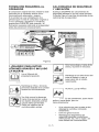
Preparation
Checklist
Refer to the Owner/Operator
required.
manual as
1. Unpack Unit - Remove shrink wrap and
packaging materials.
2. Remove Unit From Container - Open
Bypass Valves (dump valves) (See
Moving the Unff with the Engine Off on
page 15).
Push unit from container onto a level
surface. Close the bypass valves.
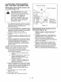
3. Tires - See Specifications
on page 30.
AUTION: Avoid injury! Explosive
separation of tire and rim parts is
possible when they are serviced
incorrectly:
Do not attempt to mount a
tire without the proper
equipment and experience
to perform the job.
Do not inflate the tires
above the recommended
pressure.
Do not weld or heat a wheel
and tire assembly. Heat can
cause an increase in air
pressure resulting in an
explosion. Welding can
structurally weaken or
deform the wheel.
Do not stand in front or over
the tire assembly when
inflating. Use a clip-on
chuck and extension hose
long enough to allow you to
stand to one side.
4. Seat - See Seat Adjustments on
page 13 and Service Position on
page 17.
5. Position Steering Levers- Rotate
eccentric spacers to align handlebars.
Tighten hardware securely. See Aligning
the Steering Levers (Figure 14) on
page 23.
6. Battery - Remove battery from unit and
charge (See Battery on page 21 ).
GB-9
7.Check
Engine
Crankcase
-Check
and
addoilifneeded.
SeeEngine
Manual
for
specifications.
8.FillEngine
FuelTank
-Addclean
fuelto
thefueltank.
IMPORTANT:
Refer
toEngine
Manual
forfuel
type.
9.Hardware
-Check
forloose
hardware.
10.Check
Safety
Interlock
System
- Check
toseethattheinterlock
system
operates
correctly
(See
Safety Interlock System
2
1
on page 12).
,_
WARNING:
OF
!NTERLOCK FAILURE
together with
improper operation can result in
severe personal injury.
11. Lubrication - Lubricate all fittings per
maintenance label under seat and check
hydrostat oil level (See Lubricate Unff on
page 22).
12. Level Deck - Check unit to ensure deck
level set at factory has been maintained
(See Leveling the Mower Deck on
page 27).
13. Check Function of all Controls - Ensure
unit runs and performs properly.
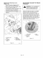
1. Steering
Levers
2. Seat
Figure 3
WARNING: FAILURE OF
CONTROLS could result in death
or serious injury.
GB-
3. Mounting
Hardware
10
OF314I
10
16
15
13
OF4035
OF4095
o_o9o
o_oe5
Figure 4
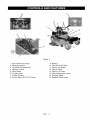
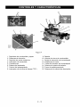
1.
2.
3.
4.
5.
6.
7.
Fuel Tanks and Caps
Steering Levers
Hydraulic Oil Reservoir
Ignition Switch
Hour Meter
Throttle Lever
Choke Control
8. Power Take Off (PTO) Switch
9.
10.
11.
12.
13.
Battery
Fuel Shut Off Valve
Mower Lift Pedal
Mower Deck
Mower Lift Lock
14. Seat Adjustment Lever
15. Parking Brake
16. Bypass Valve Lever
GB- 11
Steering Levers
WARNING:
AVOID
INJURY.
Read
andunderstand
entire
Safety section before proceeding.
B
A
CONTROLS AND FEATURES
See Figure 4 for Controls and Features
locations.
Safety
Interlock
System
D
system
failureSafety
and improper
ARNING:
interlock
operation of unit can result in
death or serious injury. Test this
system each time the unit is
operated. If this system does not
function as described, do not
operate until repairs are made.
A
The steering levers control speed and
direction. In addition, they will stop the unit.
A. For reverse travel, pull both steering
control levers backward.
B. For straight forward travel, push both
steering control levers forward.
C. To turn left, pull the left back or push
the right steering control lever forward
or a combination of both.
Perform the following tests to ensure the
safety interlock system is working properly. If
the unit does not perform as stated, contact
your Ariens dealer for repairs.
D. To turn right, pull the right back or
push the left steering control lever
forward or a combination of both.
NOTE: When the parking brake is engaged,
the steering levers are locked in neutral.
To stop, return both steering levers to neutral.
Test SteeringLevers
PTO
NOTE: The steering controls are
mechanically locked in neutral whenever the
parking brake is engaged.
NOTE: Aggressive turning can scuff or
damage lawns. ALWAYS keep both wheels
rotating when making sharp turns. DO NOT
make turns with inside wheel completely
stopped. To obtain minimum turning radius,
slowly reverse inside wheel while moving
outside wheel slowly forward.
BrakeParkingEngine
STARTING INTERLOCK
1
Neutral
Off
Engaged
Starts
2
Neutral
On
Engaged
Doesn't
Start
3
Neutral
Off
Disengaged
Doesn't
Start
OPERATING
INTERLOCK
(ENGINE ON)
4"
Neutral
On
Engaged
Shuts Off
5*
Neutral
Off
Disengaged
Shuts Off
Ignition
Operator lifts off seat.
Parking
Brake
Interlock
System
With the parking brake engaged, the steering
levers must be locked in neutral.
With the parking brake disengaged, the
engine must not start and the engine must
shut off if the operator leaves the seat.
GB-
Switch
Operate the ignition switch
with the removable key.
The switch has three
positions: Off (1), On (2)
and Start (3). To start the
engine, turn the key to
Start, then release to On.
To stop the engine, turn
the key to Off.
12
Choke
I\1
Control
Mower
Push the choke lever
forward to start a cold
engine. Pull the choke
lever to the rear when the
engine gets warm.
Throttle
Lever
!
M
OF1700
Mower lift pedal raises and lowers mower
deck for mowing or transport.
Transport:
The throttle lever changes
the engine speed. Move
the throttle lever to Fast (1)
to increase engine speed.
Move the lever to Slow (2)
to decrease engine speed.
6
Lift Pedal
{[ ll;)lll
Push mower lift pedal all the way forward until
lift lock engages.
Cutting Height:
Put cutting height adjustment pin in desired
hole. Push mower lift pedal forward and hold
it while pushing down on the lift lock. Slowly
lower mower lift pedal until deck lift contacts
cutting height adjustment pin.
Fuel Shut-Off Valve
2
Use this valve to control
fuel flow from left or right
fuel tank.
OF1700
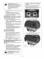
Bypass Valve Lever
Pull the lever back to set
Drive
Open the valve to
operate the engine. Turn
the valve to "Off" when
the pump in neutral and
move the unit with the
storing or transporting
the unit.
engine off.
Push the lever in to set the
Parking
pump in the drive position
and operate the unit.
÷(Q)÷
Neutral
Brake
Lever
1. Pull lever up to engage
parking brake.
2. Push lever down to
disengage parking brake.
_0F1740
Seat Adjustments
Power Take Off (PTO)
Switch
ON
Power take off (PTO)
switch engages and
disengages the mower
blades.
OFF
OE026I
,_
Pull the power take off
(PTO) switch to "On"
position to engage mower
blades.
WARNING: Make
all seat
adjustments
with unit
stationary,
parking brake on and engine shut
off.
To adjust seat forward or backward:
Push the power take off
(PTO) switch to "Off" position to disengage
mower blades.
NOTE: The engine will not start unless the
steering control levers are in the neutral
position, the PTO switch is in the "Off"
position and parking brake is set.
GB - 13
1. While seated, pull seat adjustment lever
outward and slide seat into desired
position.
2. Release lever and slide seat forward or
back to lock seat into position.
Hour
4. Check Tire Pressure
Meter
Records total number of
5. Check Hydraulic Fluid Level
hours the engine has
been run.
intervals.
IMPORTANT: Keep a
record of Hour Meter
readings for
recommended Lubrication
and Maintenance
NOTE: For accurate readings be sure Ignition
Switch is OFF when unit is not in operation.
6. Adjust Seat
Be sure all controls can be reached safely
from operator's position.
7. Set Cutting Height
Make sure the deck is set to the correct
cutting height.
STOPPING
IN AN EMERGENCY
The unit can be stopped immediately at any
time by turning the ignition key to the "Off"
position.
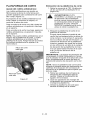
FILLING FUEL TANK
WARNING: AVOID INJURY.
Read and understand entire
Safety section before proceeding.
STARTING
Add fuel to Fuel Tank as needed. See your
Engine Manual for correct type and grade of
fuel.
,_
AND SHUT
OFF
Owner/Operator
CAUTION: Read Manual,
entire Clutch
Manual, and Engine Manual first.
DO NOT attempt to start engine
at this time.
To add fuel to the fuel tank:
1. Place unit in an open or well-ventilated
open area.
2. Stop the engine and allow it to cool.
3. Clean the fuel cap and the area around
the fuel cap to prevent dirt from entering
the fuel tank. Remove the cap from the
fuel tank.
1. Make sure the steering levers are in
neutral.
4. Fill the fuel tank to within 1 in. (25 mm)
below bottom of filler neck.
2. Put the PTO switch in the "Off" position.
3. Engage parking brake.
4. If the engine is cold, move the choke
control to the "On" position. If the engine
is warm or hot, do not use choke.
5. Replace fuel cap and tighten.
6. Clean up any spilled fuel.
5. Move the throttle to 3/4 "Fast" position.
See Engine Manual for detailed
instructions.
PRE-START
,_
1.
To start the engine:
6. Put the ignition key in the switch and
turn it to the "Start" position.
7. As soon as the engine starts, release the
key.
8. Move the choke control to the "Off"
position from the "Choke" position. Wait
until the engine is running smoothly
before operation.
To stop the engine:
CAUTION: is Make
hardware
tight, all
suresafety
all
devices are in place and all
adjustments are made correctly.
Check
Safety
Interlock
System
1. Bring the steering levers to neutral.
Disengage the PTO and engage the
parking brake.
2. Move the throttle lever to the "Slow"
position.
3. Turn the ignition key to the "Off" position.
If this system does not function as described
do not operate until repairs are made.
2.
Check
Air Cleaner
Check air filter for dirt. Clean as required.
Follow Engine Manual Maintenance
Schedule.
3. Check
Oil
Engine
Fuel and
TO MOW WITH UNIT
Crankcase
Operate the unit only when seated in the
operator's position.
Check and add fuel if required. Check that
engine crankcase oil is full. Follow Engine
Manual Maintenance Schedule.
1. Start the engine. Let the engine warm
until it is running smoothly.
2. Release parking brake.
GB-
14
,_
WARNING:
steering
control
leversMove
slowlytheand
keep the
throttle control lever at slow
speed until you learn how to
operate the unit.
3. Bring the steering levers to neutral.
4. Slow the engine down to about 3/4
speed.
5. Turn ON the PTO switch to engage the
mower.
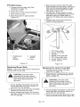
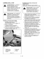
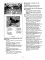
Push Lever In to Drive Position
IMPORTANT: Never engage the PTO if the
mower is plugged with grass or other
material. This may cause damage to the
electric clutch.
6. Move throttle control to fast.
7. Move the steering levers forward to
obtain a slow ground speed.
8. To disengage the mower, move the PTO
switch to the "Off" position.
9. When you know how to operate the unit,
select a speed appropriate to your
mowing conditions.
PARKING
To park the unit:
1. Bring the steering levers to neutral. Turn
off PTO.
2. Move the throttle lever to the "Slow"
position.
3. Engage the parking brake.
4. Lower the attachment.
Pull Lever Out to the Neutral Position
5. Turn the ignition key to the "Off" position
and remove the key.
MOVING THE UNIT WITH THE
ENGINE OFF
IMPORTANT:
Never tow unit.
1. Shut OFF engine.
2. Place seat in the service position (See
Service Position on page 17).
3. Pull the right and left bypass levers to
the neutral position.
,_
©F4110
Figure 5
WARNING: Do
not on
bypass
transmission
when
a slope.
4. Disengage parking brake.
5. Push unit to desired location.
6. Engage parking brake.
7. Push the right and left bypass levers to
the drive position.
GB- 15
FOR BEST PERFORMANCE
Mow with the engine set at full throttle.
Cut grass when it is dry.
When mulching, only remove 1/3 of grass
length per cutting. Do not cut more than 1
inch (2.54 cm) at any one time.
Keep mower blades sharp.
Keep mower deck properly levelled.
Adjust anti-scalp
Discharge clippings into areas already cut.
rollers to prevent scalping.
Do not set height of cut too low. For very tall
grass, mow twice.
Do not travel too fast.
Vary cutting pattern with each mowing.
Do not allow grass or debris to collect inside
of mower deck. Clean after each use.
Proper maintenance can prolong the life of
unit. The following charts show the
recommended service schedule. More
WARNING: AVOID INJURY.
Read and understand entire
Safety section before proceeding.
frequent
working
ambient
airborne
See the
service may be required due to
conditions (heavy loads, high
temperatures, dusty conditions, or
debris).
maintenance instructions in the
Engine Manual for additional information.
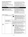
Period
Service
Task
Check Safety Interlock
failure
and improper
operationsystem
of unit can
WARNING:
Safety interlock
result in death or serious injury. Test this
system each time the unit is operated. If
this system does not function as
described, do not operate until repairs are
made. See Safety Interlock System on
page 12.
Each
Use
Check Parking Brake
Interlock System
See Parking Brake Interlock System on page 12.
Check Hydraulic Fluid
Check hydraulic oil level mark on cap/dipstick. Add
15W50 synthetic oil as needed. Do not overfill. See
Check Hydraulic Fluid Level on page 18.
Check Tires
See Specifications
pressure.
,_
on page 30 for correct tire
separation
tire and
rim Explosive
parts is possible
CAUTION: of
Avoid
injury!
when they are serviced incorrectly:
•Do not attempt to mount a tire without the
proper equipment and experience to
perform the job.
•Do not inflate the tires above the
recommended pressure.
Do not weld or heat a wheel and tire
assembly. Heat can cause an increase in air
pressure resulting in an explosion. Welding
can structurally weaken or deform the
wheel.
Do not stand in front or over the tire
assembly when inflating. Use a clip-on
chuck and extension hose long enough to
allow you to stand to one side.
GB-
16
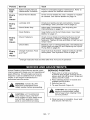
Period
Service
Task
Each
Use
Follow Engine Manual
Maintenance Schedule
Perform scheduled engine maintenance.
engine manual for detailed instructions.
Every
25
Check Mower Blades
Check mower blades for wear. Sharpen or replace
as needed. See Mower Blades on page 19.
Every
50
Lubricate Unit
Oil all pivot points and pin connections. Grease
lube fittings. See Lubricate Unit on page 22.
Hours
Check Brake Gap
Adjust gap if nessessary. See Adjusting
Parking Brake on page 24.
Clean Battery
Keep battery and its terminals clean. See Clean
Batteryon page 21.
Check Fasteners
Check mower blade mounting hardware and all
other fasteners. Replace missing or damaged
fasteners. Tighten all nuts and bolts to their correct
torque value.
Check Belts
Replace worn or deteriorated belts. See Replacing
Mower Belts on page 25 and Replacing the Hydro
Pump Belt on page 25.
Change Hydraulic Fluid
and Filter*
Drain hydraulic fluid tank, replace hydraulic oil filter,
refill system. See Hydraulic Fluid on page 18.
Refer to
Hours
Every
100
Hours
Every
400
the
Hours
*Change hydraulic fluid and filter after first 75 hours of operation.
Ariens Dealers will provide any service which
may be required to keep your unit operating at
peak efficiency. Should engine service be
required, it can be obtained from a Ariens
Dealer or the engine manufacturer's
authorized service center.
SERVICE POSITION
1. Place unit on a flat level surface.
ALWAYS stop engine. Ensure unit is
secure and will not tip over. Strap and
clamp onto lift if used.
2. Place steering levers in neutral and
engage parking brake.
3. Remove hex nut.
WARNING: AVOID INJURY.
Read and understand entire
Safety section before proceeding.
4. Tip seat forward (Figure 6).
,_
,_
CAUTION:
SURFACES
may result inHOT
injury.
DO NOT
touch engine or drive parts which
are hot from operation. Allow
parts to cool before servicing.
CAUTION:
Be sure footing
secure
to accomodate
weightis
shift of seat when rotating it into
service position.
5. When service is complete, lower seat
and secure with hex nut.
GB - 17
Check
1
Hydraulic
Fluid
Level
Check the system with the unit cold and
parked on a flat, level surface.
Then run the unit for about one minute and
recheck the levels.
\
To Add
Hydraulic
Fluid:
1. Remove the cap from the expansion
tank.
2. Fill the expansion tank with Mobil 1
Extended Performance 15W50 or
equivalent (Ariens p/n 00057100) until
oil level reaches the cold fill line on the
tank.
3. Install the expansion tank cap and then
purge the system. See Purging the
Hydraulic System on page 19.
The hydraulic fluid should be at the cold
fill line of the expansion tank.
4
1. Service
Position
3. Parking Brake
4. Battery
2. Steering
Levers
Figure 6
HYDRAULIC
FLUID
WARNING: HYDRAULIC FLUID
can result in severe burns. Fluid
in hydraulic system can penetrate
skin and result in serious injury or
death.
Be sure to stop the engine before
doing any work on hydraulic
parts.
Figure 7
Keep body and hands away from
pin holes or nozzles which expel
hydraulic fluid when under
pressure. Use paper or
cardboard, not hands, to search
for leaks.
Change
Hydraulic
Fluid
and Filter
NOTE: Change hydraulic fluid and filter after
first 75 hours of operation. Change the
hydraulic oil filter and hydraulic oil every 400
hours. Use Mobil 1 Extended Performance
15W50 Synthetic Oil or equivalent for best
component life (Ariens p/n 00057100).
1. Place container under oil filter to catch
oil.
Ensure all hydraulic fluid
connections are tight and all
hydraulic hoses and lines are in
good condition before applying
pressure to system.
FOREIGN FLUID INJECTED
INTO BODY can result in
gangrene. Fluid must be
surgically removed within a few
hours by a doctor familiar with
this form of injury.
2. Remove the filter guard and oil filter from
the transaxle.
3. Remove the oil drain plug or fitting from
the inlet port and allow the transaxle to
drain completely.
4. Clean the filter mounting surface and
then lubricate rubber gasket on new oil
filter with clean hydraulic oil.
GB-
18
5.Spin
new
oilfilteronto
filterhousing
until
itmakes
contact.
Tighten
oilfilter
another
3/4turn.
6.Install
thefilterguards
removed
in
step2.Tighten
themounting
screws
to
65Ibf-in
(7.3N°m).
7.Repeat
steps
1-6fortheother
transaxle.
8.Follow
theinstructions
inTo Add
4. Stop the engine and put the transaxle
bypass levers in the drive position. See
Moving the Unff with the Engine Off on
page 15.
5. Start the engine and slowly move the
steering levers in forward and reverse
five or six times.
6. Stop the engine, check the oil level and
add oil as needed.
Hydraulic Fluid: on page 18.
7. Repeat steps 2-6 until the transaxles
operate smoothly in forward and reverse
at normal speeds without excessive
noise.
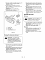
MOWER BLADES
Remove
3
_IL
AUTION:
Use sturdy
gloves
padding
to protect
hands
when or
working with mower blades.
1. Turn the engine off. Remove the ignition
key. Remove the ignition wire from the
spark plugs.
2. Remove the bolts, cup washer, and
blades from the spindle shafts.
Replace
1. Drain Plug
2. Oil Filter
3. Filter Guard
1. Put the blades, cup washers, and the
bolts back on the spindle shafts.
2. Tighten the bolts to a torque of 115125 Ibf-ft (156-169.5 N°m).
3. Replace the ignition wire on the spark
plugs.
4. Mounting Hardware
Figure 8
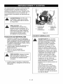
Purging the Hydraulic System
WARNING: This adjustment
requires operating the engine.
Use extreme care to avoid
contact with moving parts and hot
surfaces. Be sure rear of unit is
well supported and secure before
starting engine.
1. With the unit up to and facing a wall, jack
up the unit so that both drive wheels are
off the ground.
2. Disengage the parking brake and put the
transaxle bypass levers in the neutral
position. See Moving the Unff with the
Engine Off on page 15.
3. Start the engine and slowly move the
steering levers in forward and reverse
five or six times.
GB - 19
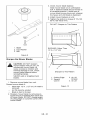
3. Check mower blade balance.
Slide mower blade on an unthreaded
bolt. A balanced blade should remain in
a horizontal position. If either end of
mower blade moves downward, sharpen
the heavy end until blade is balanced.
4. Install mower blade(s) on unit.
5. Tighten the bolts to a torque of 115-125
Ibf-ft (156-169.5 N°m).
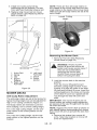
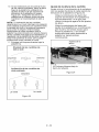
DO NOT Sharpen to This Pattern
2
2
/
1.Blade
2. Cup
Washer
3. Bolt
1
DIS
1/2 in. (1.27 cm)
Figure
9
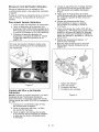
Sharpen the Mower Blades
,_
mower
blades
unit. An
CAUTION:
DOwhile
NOT on
sharpen
unbalanced mower blade will
cause excessive vibration and
eventual damage to unit. Check
mower blade balance before
reinstalling blades.
NEVER weld or straighten
blades.
3
/
OT0792
4
Sharpen to This Pattern
bent
1. Cutting Edge
2. Square
Corner
1. Remove mower blade from unit.
Discard mower blade if:
More than 1/2 in. (1.27 cm) of metal is
removed.
Air lifts become eroded.
Blade is bent or broken.
2. Sharpen mower blade by removing an
equal amount of material from each end
of mower blade. DO NOT change angle
of cutting edge or round the corner of the
mower blade.
GB - 20
Figure 10
3. Air Lift
Erosion
4. Air Lift
BATTERY
WARNING: AVOID INJURY.
Read and understand entire
Safety section before proceeding.
WARNING: Battery posts,
terminals and related accessories
contain lead and lead
compounds, chemicals known to
the State of California to cause
cancer and reproductive harm.
Wash hands after handling.
Unit comes equipped with a maintenancefree battery that requires no regular
maintenance except cleaning the terminals.
Remove
1. Negative
terminal
2. Positive
terminal
Battery
1. Shut OFF engine. Engage parking
brake. Remove the ignition key.
2. Place seat in the service position (See
Maintenance Schedule on page 16).
3. Disconnect cables from battery
(negative, then positive)(Figure
11).
4. Remove hold down and remove battery.
Replace
Figure 11
1. Remove battery from unit. See Remove
Battery on page 21.
2. Clean terminals and battery cable ends
with wire brush.
Battery
3. Coat terminals with dielectric grease or
petroleum jelly.
4. Replace battery. See Replace Batteryon
page 21.
1. Replace battery and secure with battery
hold down.
2. Reconnect cables to battery (positive,
then negative). Position boot over
positive terminal.
3. Return seat to operating position.
Clean
Charging
Battery
Keep battery and its terminals clean. Inspect
every 100 operating hours or monthly for best
performance.
3. Battery
the Battery
Battery Electrolyte
First Aid
Follow First Aid directions for contact with
battery fluid.
External Contact: Flush with water.
Eyes: Flush with water for at least 15
minutes and get medical attention
immediately!
Internal Contact: Drink large quantities
of water. Follow with Milk of Magnesia,
beaten egg or vegetable oil. Get
medical attention immediately!
In case of internal contact, DO NOT induce
vomiting!
IMPORTANT: DO NOT fast charge. Charging
at a higher rate will damage or destroy
battery. ONLY use an automatic charger
designed for use with your battery.
ALWAYS follow information provided on
battery by battery manufacturer. Contact
battery manufacturer for extensive
instructions to charge battery.
1. Remove battery from unit. See Remove
Battery on page 21.
GB - 21
2.Place
battery
onbench
orother
wellventilated
place.
3.Connect
positive
(+)leadofcharger
to
positive
(+)terminal,
andnegative
(-)
leadtonegative
(-)terminal.
4.Charge
battery
according
tocharger
and
battery
manufacturers'
instructions.
5.Replace
battery.
SeeReplace Batteryon
page 21.
Jump-Starting
Ariens does not recommend jump-starting
your unit. Jump-starting can damage engine
and electrical system components. See your
engine manual for more detailed information.
LUBRICATE
UNIT
2. With the unit up to and facing a wall, jack
up the unit so that both drive wheels are
off the ground.
3. Remove the drive wheels from the unit.
4. Start the engine, run engine at full
throttle, and release the parking brake.
5. Move the steering levers from Forward
to Reverse several times to make sure
controls are free. Then return steering
levers to neutral position.
6. Check wheel(s) for movement.
NOTE: The right and left hydraulic pumps are
adjusted the same way.
7. If a wheel moves, adjust the return to
neutral mechanism on the hydraulic
pump:
a. Loosen the return to neutral screw
Apply oil at all pivot points and pin
connections.
on the pump.
b. Slowly move the speed and
direction control bracket clockwise
or counterclockwise until the
wheel stops moving.
c.
8. Move steering levers from Forward to
Reverse several times and return
steering levers to neutral position.
Check wheel(s) for movement.
9. If wheel is still moving, repeat steps 7
and 8.
OF1794
R LUBRICA- QTY
E
TION
F
1 REPACK
2
OIL
LOCATION
Hold the stop bracket in position
and tighten the return to neutral
screw on the pump.
INTERVAL
CASTER
400 Hrs
PIVOT
ALL PIVOT 50 Hrs
POINTS, PIN
CONNECTIONS
10. Shut OFF engine.
11. Replace drive wheels.
Axle Direction
.. ...........
_
Return to Neutral
Adjusting Screw
Figure 12
STEERING CONTROL NEUTRAL
ADJUSTMENT
Eliminating Excessive Creeping of
the Unit (Figure 13)
A
Speed and
Direction
Control Arm
WARNING: This adjustment
requires operating the engine.
Use extreme care to avoid
contact with moving parts and hot
surfaces. Be sure rear of unit is
well supported and secure before
starting engine.
Figure 13
1. If hydraulic system is cold, run unit for a
minimum of five minutes, then shut OFF
engine.
GB - 22
Aligning
the Steering
(Figure 14)
ADJUSTING THE UNIT TO TRACK
STRAIGHT
Levers
1. Shut OFF engine. Engage parking
brake. Remove the ignition key.
2. Place seat in the service position (See
Service Position on page 17).
3. Loosen brake interlock on the same side
as steering lever to be adjusted.
4. Loosen tie rod jam nuts and turn tie rod
until steering levers are aligned.
5. Tighten jam nut on tie rod, tighten brake
interlock.
_1
ARNING:
Prior
adjusting
tracking
of the
unit,toshut
OFF the
engine, engage parking brake,
and remove the ignition key.
Check and adjust tire pressure. Increase
pressure on side unit tracks to. DO NOT
exceed maximum recommended tire
pressure (See Specifications
1. Limiter Bolt
2. Jam Nut
3. Steering
Lever
1. Tie-Rod Jam
Nut
4. Brake
Interlock
2. Tie-Rod
3. Steering
Lever
5. Hydrostatic
Transmission
Figure 14
on page 30).
If tire pressure adjustment does not solve
tracking problem, adjust the limiter bolts on
the stop bracket (Figure 15). Front bolts
adjust forward and rear bolts adjust reverse.
Lengthen the limiter bolt (move closer to
lever) on side which is too fast.
3
Figure 15
OF3381
GB - 23
4. Stop
Bracket
ADJUSTING THE HEIGHT OF THE
STEERING LEVER HANDLES
1. Engage parking brake and set both
transmission bypass valves to the
neutral position. See Moving the Unit
with the Engine Off on page 15.
2. Push the unit forward.
The handles have three height positions
(Figure 16).
If the unit easily rolls forward
transmission brakes are not
engaging. Tighten the brake
fully engage the brake lever
transmission.
Adjust
Position # 1
Position # 2
Position # 3
the Parking
the
fully
cable to
on the
Brake
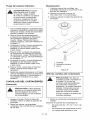
1. Disengage the parking brake.
2. Loosen the nuts on the parking brake
cable adjuster and then turn the adjuster
until the cable is taut, not tight.
3. Engage the parking brake and check the
adjustment. Repeat as needed.
4. Tighten the nuts.
NOTE: Set both bypass valves to the drive
_osition when finished adjusting the brake.
4
1. Spacer
2. Handle
3. Eccentric
Spacer
4. Steering
Lever
Figure 16
OF3745
1. Shut OFF engine. Engage parking
brake. Remove the ignition key.
2. Remove the spacer, handle, and
eccentric spacer from the steering lever.
NOTE: Position the right and left handles at
the same height position.
3. Install the spacer, handle, and eccentric
spacer in the appropriate height position.
Do not tighten the nut holding the
eccentric spacer.
4. Turn the eccentric spacer until the right
and left handles are the same height.
Tighten nut.
ADJUSTING THE PARKING
BRAKE
1. Parking Brake Cable
2. Adjuster
3. Nuts
Figure 17
PTO BELT
_
cutARNING:
or amputate
MOVING
body PARTS
parts. can
ALWAYS wait for moving parts to
stop before performing
maintenance or service.
_
WORN
AUTION:
BELTS
DAMAGED
may result
ORin
injury and/or damage to unit.
Check belts for excessive wear or
cracks often.
The parking brake should not need
adjustment, however if the parking brake
does not hold the unit properly, the brake may
need adjustment.
Check
Adjustment
NOTE: Be sure to check the parking brake on
both sides of the unit (Figure 17).
GB - 24
PTO Belt Access
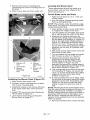
4. Remove short mower belt from right
blade spindle and from deck. Idler pivot
bolt must be loosened slightly to gain
clearance to remove belt from under
idler pulley (Figure 19).
5. Arrange new mower belt(s) on deck
(short belt first). Retighten short mower
belt idler pivot bolt. Install belts on
sheaves. Put belts onto center sheave
last.
1. Properly stop and park unit (See
Operation on page 12).
2. Lower the mower.
3. Place seat in most rearward position.
4. Remove belt covers.
5. Place foot board in open position
(Figure 18).
6. Replace belt covers and return foot
board to closed position.
1
2
2
1
1. Footboard
open
position
in
1.
2.
3.
4.
5.
6.
7.
2. Support
Frame
3. Pivot
Figure 18
Replacing
Mower
PTO Mower Belt
Mower Drive Belt
Springs
Mower Drive Belt Idler
PTO Mower Belt Idler
Mower Clutch Sheave
Center Sheave
Figure 19
Belts
Replacing
NOTE: Long mower belt must be removed to
remove short mower belt.
_
7
AUTION:idler
Usespring
care when
releasing
tension.
Keep body parts well away from
idlers when performing this
operation.
,_
1. Slowly release the tension on the long
mower belt idler until all the tension is
removed from the springs.
2. Remove long mower belt from left blade
spindle and remove from deck.
3. Slowly release the tension on the short
belt idler until all the tension is removed
from the springs.
GB - 25
the Hydro
Pump
Belt
1. Properly stop and park unit (See
Operation on page 12).
2. Remove the PTO belt from the mower
clutch sheave (See Replacing Mower
Belts on page 25).
releasing idler
CAUTION:
Usespring
care when
tension.
Keep body parts well away from
idlers when performing this
operation.
3. Slowly release the tension on the hydro
pump belt idler until all the tension is
removed from the springs.
4. Remove old hydro pump belt from right
hand hydrostat sheave first (Figure 20).
5.Install
new
hydro
pump
beltby
positioning
beltonsheaves.
Putbelt
ontorighthand
hydrostat
sheave
last.
6.Replace
longmower
beltonmower
clutch
sheave.
SeeReplacing Mower
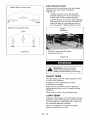
NOTE: There are four anti-scalp rollers on
the outside of the mower deck and four antiscalp rollers on the inside of the mower deck.
Make sure all anti-scalp rollers are set at the
same height.
Belts on page 25.
Lowest Cutting
Height
2J
1
©
/
Hig
Cutting
Height
Figure 21
Removing
the Mower
Deck
1. Remove PTO belt (See Replacing
Mower Belts on page 25).
,_
OF1631
6. Left Hand
Hydrostat
7. Clutch
8. Clutch
Anchor
1. Hydro Belt
2. Spring
3. Idler
4. Engine
Sheave
2. Lock the mower deck in the service
position.
Push the mower lift pedal forward
between cutting height number 4 and
number 5 to align the holes in the deck
lift shaft and the deck lift cover. Insert the
cutting height pin in the holes on the side
of the deck lift cover so it passes all the
way through the deck lift cover and
shaft.
5. Right Hand
Hydrostat
Figure 20
MOWER DECKS
Anti-scalp
Roller
Adjustment
The anti-scalp rollers are set at the factory for
typical mowing height, but can be adjusted for
high or low cutting conditions (Figure 21).
Anti-Scalp rollers are intended to prevent
lawn scalping, not to control cutting height.
For a very high cutting height, set the antiscalp rollers in the lowest position on the
bracket.
For a very low cutting height, set the antiscalp rollers in the highest position on the
bracket.
Mower
lift arms
and INJURY.
mower lift
WARNING:
AVOID
pedal could cause severe injury if
they are not locked before
removing the mower deck.
ALWAYS lock mower deck lift
before removing the deck.
IMPORTANT: The mower lift arms are not
locked unless the cutting height adjustment
pin passes all the way through both the deck
lift cover and shaft.
NOTE: Support the mower deck on blocks or
jack stands before disconnecting link chains
from mower lift arms to prevent the deck from
falling.
3. Remove link chains from mower lift
arms. Note hole location on mower lift
arms for replacement.
GB - 26
4.Remove
themower
mounting
pins
connecting
themower
mounting
arms
to
thedeck.
5.Slide
mower
deck
outfromunder
unit.
Leveling
the Mower
Deck
These adjustments should be made on a
level surface with the tires inflated to the
correct air pressure.
Check Blade Level and Pitch
1.Mower
Lift 4. Mower
Arm
Mounting
2. Link
Chain
Pin
3. Mower
5.Mower
Lift
Mounting
Arms
Arm
Locked
Figure
22
OF3765
Installing the Mower Deck (Figure
1. Slide mower deck under unit.
22)
2. Connect mower mounting arms to deck
with mower mounting pins.
3. Install link chains on the mower lift arms
in the same holes they were removed
from.
4. Install PTO mower belt (See Replacing
Mower Belts on page 25).
5. Level mower deck (See Leveling the
Mower Deck on page 27).
1. Raise mower deck to a 3 in. (7.62 cm)
cutting height.
2. Shut off engine. Engage parking brake.
Remove the ignition key.
NOTE: Place blocks under the bottom edge
of the deck, not under the reinforcement bar
welded along deck face.
3. Place blocks at each corner of the deck
to support the weight of the deck.
4. Turn the blades so the blade ends point
left to right across the width of the deck.
5. Measure the distance between the
ground and cutting edge of the blade on
the left blade (Left position in Figure 23)
and on the right blade (Right position in
Figure 23). Distances should be within
3/16 in. (4.7 mm). If they are not, raise
the low side of the deck using the height
adjusters on the deck lift brackets (see
Figure 24).
6. After deck is level side to side, check the
deck front to back pitch.
7. Turn the blades so the blade ends point
front to back as shown in Figure 23.
8. Measure the distance between the
ground and the cutting edge of the
middle blade at the front of the deck
(Front position in Figure 23) and
between the ground the cutting edge of
the left and right blades at the rear of the
deck (Rear position in Figure 23).
9. The cutting edge at the front of the deck
(Front position in Figure 23) should be
1/8 in. (3.18 mm) lower than the cutting
edges at the rear of the deck (Rear
position in Figure 23).
10. If measurements are out of range, raise
the low side of the deck using the height
adjusters on the deck lift brackets (see
Figure 24). Be sure to raise the deck
evenly to keep the deck level side to
side.
NOTE: Pitching the front of the blades lower
than the rear provides a balance between cut
quality and the power needed to cut grass.
Certain cutting conditions require the deck to
be pitched with the rear of the blades lower
than the front. Heeling the deck this way
requires more engine power but can provide
better cut quality.
11. Remove the blocks from under the deck.
GB - 27
Blade
Side-to-Side
Level
Adjust
Blade
Height
Level and pitch the mower with the height
adjusters on each deck lift bracket
(Figure 24).
Loosen the jam nut on the deck lift
bracket bolt about 1/4 turn to reduce
clamp load on the height adjusters.
Loosen the jam nut on the deck adjuster
bolt and then turn the bolt clockwise to
raise the deck or counterclockwise to
lower the deck. Tighten both jam nuts.
\
Blade Front-to-Back
Pitch
Height
Adjusters
Front
Rear
Rear
DO NOT place blocks under
reinforcement bar.
Figure 23
Figure 24
,_11
Read and understand
entire
WARNING:
AVOID INJURY.
Safety section before proceeding.
SHORT TERM
NEVER spray unit with high-pressure
or store unit outdoors.
water
Inspect unit for visible signs of wear,
breakage or damage.
Keep all nuts, bolts and screws properly
tightened and know unit is in safe working
condition.
Store unit in a cool, dry protected area.
LONG TERM
Clean unit thoroughly with mild soap and low
pressure water and lubricate (See Lubricate
Unff on page 22 in Maintenance). Touch up
all scratched painted surfaces.
Remove weight from wheels by putting
blocks under frame or axle.
GB - 28
When
storing
unitforextended
periods
of
P_'__o_;_]_,,,,_
time,
remove
allfuelfrom
tankandcarburetor
(rundry).Refer
toEngine
Manual.
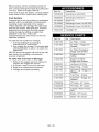
Part No.
Description
Clean
andcharge
thebattery.
Charge
battery 79206400
Mulching Kit (991039)
every
three
tofourweeks
when
storing
unit.
79206500
Mulching Kit (991041)
FuelSystem
Gasoline
leftinthefuelsystem
forextended 79100500 Striper Kit
periods
without
astabilizer
willdeteriorate, 79100800 Discharge Cover Kit (991039)
resulting
ingumdeposits
inthesystem.
These
deposits
candamage
thecarburetor 79206800 Discharge Cover Kit (991041 )
andthefuelhoses,
filterandtank.
Prevent 79202700
Headlight Kit
deposits
fromforming
inthefuelsystem
during
storage
byadding
aquality
fuel
stabilizer
tothefuel.Follow
the
recommended
mixratiofound
onthefuel
stabilizer
container.
Part No.
Description
Totreat
thefuelsystem
forstorage:
21547700
1
Air Filter - Kohler
1.Addfuelstabilizer
according
to
manufacturers'
instructions.
21531500
1
Air Filter - Briggs and
Stratton
2.Runengine
foratleast
10minutes
after
adding
stabilizer
toallow
ittoreach
the 21531600 1 Air Filter Precleaner carbu
retor.
Briggs and Stratton
NEVER
store
theengine
withfuelinthefuel
tankinside
ofabuilding
withpotential
21397200
1
Engine Oil Filter Kohler
sources
ofignition.
21530700
ToTaketheUnitOutofStorage
1
Engine Oil Filter Briggs and Stratton
1.Refer
totheengine
service
manual
to
prepare
theengine
forservice.
00669300
2
Hydraulic Oil Filter
2.Putfresh,
clean
fuelinthefueltank.
21541700
2
Spark Plug - Kohler
3.Begin
themaintenance
schedule.
4.Charge
andinstall
thebattery.
21531100
2
Spark Plug - Briggs and
Stratton
21541500
1
Fuel Filter-
21531800
1
Fuel Filter - Briggs and
Stratton
07200026
1
PTO Belt - 52" Decks
07200028
1
PTO Belt - 60" Decks
07211500
1
Traction (Hydro Pump)
Belt
03253800
1
Blade - 52" Decks
03253900
1
Blade - 60" Decks
GB - 29
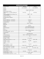
Kohler
Model Number
Model
Engine
Engine
Briggs & Stratton ELS
Engine Model Number
Engine Power - hp (kW) at Maximum
RPM
24 (17.9)
26 (19.4)
3600 +/- 100
Governed RPM (May be different from
maximum RPM)
Liquid or Air Cooled
Air
Cooling System Capacity
NA
Speed
Forward Maximum - mph (km/h)
Reverse Maximum
7.0 (11.3)
- mph (kmth)
4.0 (6.4)
Zero
Turning Radius
Brakes
Hydro - Parking
Electrical
Starter
Electric
Battery
12-Volt Maintenance
Power Take-Off
Electric PTO Clutch/Brake
Free
Fuel
Fuel Type
Refer to Engine Manual
Fuel Tank Capacity - gal. (L)
7 (26.5)
Transmission
Type
Transmission
Hydrostatic
Oil
Drive
Mobil 1 15W-50 Synthetic
or Equivalent
Yes
Hydraulic Oil Filter
Size and Weight
Length - in. (cm)
71.5 (181.6)
Width (With Chute Up) - in. (cm)
63.0 (160)
63.0 (160)
Height - in. (cm)
42 (106)
Weight - Ibs (kg)
830 (377)
830 (377)
Tires
13x 5-6
Front Tire Size - in, (cm)
20 x 10-10
Rear Tire Size - in, (cm)
Front Tire Pressure-
psi (kPa)
Rear Tire Pressure-
psi (kPa)
20 x 10-10
20- 25 (138 -172)
15 -18 (103 -124)
15 -18 (103 -124)
Mower Deck
Mower Deck Lift
Mechanical
Cutting Width - in. (cm)
52 (132)
Cutting Height - in. (cm)
Cutting Height Increments
60 (152)
1 - 5 (2.5- 12.7)
- in. (cm)
0,5 (1,25)
GB - 30
Ariens Limited
Warranties
2-Year Limited Lawn and Garden
Consumer Warranty
Ariens Company (Ariens) warrants to the
original
purchaser
that Ariens and Gravely
brand consumer products manufactured
by
Ariens Company will be free from defects in
material and workmanship
for a period of two (2)
years after the date of purchase, and that Ariens
will repair any defect in material or workmanship,
and repair or replace any defective part, subject
to the conditions,
limitations and exclusions set
forth herein. Such repair or replacement
will be
free of charge to the original
purchaser
(labor
and parts), except as noted below.
The two-year duration of this warranty applies
only if the product is put to ordinary, reasonable,
and usual personal, family, or household uses. If
the product is put to any business, commercial,
or industrial use such as, but not limited to,
commercial
landscaping,
mowing or snow
removal services, or golf course or park
maintenance,
or agricultural or farmstead
use,
then the duration of this warranty is ninety (90)
days after the date of purchase, or one (1) year
after the date of purchase if the product is
labeled as a Professional/Commercial
Product.
The duration of this warranty shall be ninety (90)
days after the date of purchase if any product is
rented or leased.
2-Year Limited Lawn and Garden
Commercial Warranty
The Ariens Company (Ariens) warrants to the
original
purchaser
that all Gravely Pro and
ProMaster
products manufactured
by Ariens will
be free from defects in material and
workmanship
for a period of two (2) years after
the date of purchase or 1000 hours of use,
whichever comes first. An authorized Gravely
dealer will repair any defect in material or
workmanship,
and repair or replace any
defective part, subject to the conditions,
limitations and exclusions set forth herein. Such
repair or replacement
will be free of charge to
the original
purchaser
(labor and parts), except
as noted below.
The duration of this warranty shall be ninety
(90) days after the date of purchase or 1000
hours of use, whichever comes first, if any
product is rented or leased.
Ariens Company • 655 W. Ryan St. •
Brillion, WI 54110-1072. (920) 756-2141
3-Year Limited Sno-Thro Warranty
Ariens Company (Ariens) warrants to the
original
purchaser
that Sno-Thro products
manufactured
by Ariens Company will be free
from defects in material and workmanship
for a
period of three (3) years after the date of
purchase, and will repair any defect in material
or workmanship,
and repair or replace any
defective part, subject to the conditions,
limitations and exclusions set forth herein. Such
repair or replacement
will be free of charge to
the original
purchaser (labor and parts), except
as noted below.
The three-year
duration of this warranty
applies only if the product is put to ordinary,
reasonable,
and usual personal, family, or
household uses. If the product is put to any
business, commercial,
or industrial use, then the
duration of this warranty is ninety (90) days after
the date of purchase, or one (1) year after the
date of purchase if the product is labeled as a
Professional/Commercial
Product. The duration
of this warranty shall be ninety (90) days after
the date of purchase if any product is rented or
leased.
DURA-CLEAN TM Auger Limited
Lifetime Warranty
Ariens Company (Ariens) warrants to the
original
purchaser
that the rubber components
of the DURA-CLEAN
TM
Auger manufactured
by
Ariens Company will be free from defects in
material and workmanship
and will not wear out
for the life of the Sno-Thro,
except as noted
below.
Ariens Company will provide for the
replacement
of any of the rubber components
of
the DURA-CLEAN
TM
Auger found upon
examination
by the Ariens Company to be
defective or worn out. Replacements
will be
supplied free of charge. Labor is not included
after two (2) years from the date of purchase of
the Sno-Thro.
The lifetime limited warranty shall apply if the
product is put to ordinary, reasonable,
and usual
personal household use. If the product is put to
any business, commercial,
industrial, rental, or
leased use, the warranty shall be against defects
in material and workmanship
for ninety (90) days
following the date of purchase.
ALW2-62905
• www.ariens.com
Exceptions,
These
warranties
are subject
To obtain warranty service,
conditions must be met:
Limitations, Exclusions
to the following
the following
The purchaser
must perform the
maintenance
and minor adjustments
explained
in the owner's manual.
The purchaser
must promptly notify Ariens
Company or an authorized Ariens service
representative
of the need for warranty
service.
The purchaser
must transport the product
to and from the place of warranty service.
Warranty service must be performed by a
respective
Ariens or Gravely authorized
service representative.
To find an Ariens or Gravely authorized
service representative,
contact Ariens at:
655 W. Ryan St, RO. Box 157
Brillion, WI 54110-0157
(920) 756- 2141
www.ariens.com
This warranty
limitations:
www.gravely.com
is subject to the following
Genuine Ariens or Gravely brand service
parts and accessories
not purchased with
the product covered by this warranty, but
which are later purchased and used with
that product, are warranted to be free from
defects in material and workmanship
for a
period of ninety (90) days after date of
purchase, and Ariens Company will repair
or replace any such part or accessory free
of charge, except for labor, during that
period.
Batteries are warranted
only for a period of
twelve (12) months after date of purchase,
on a prorated basis. For the first ninety (90)
days of the warranty period, a defective
battery will be replaced free of charge. If
the applicable warranty period is more than
90 days, Ariens Company will cover the
prorated cost of any defective battery, for
up to twelve (12) months after the date of
purchase.
conditions,
limitations,
and exclusions:
The following items are excluded from this
warranty:
Engines and engine accessories are covered
only by the engine manufacturer's warranty
and are not covered by this warranty.
Hydro-Gear transmissions
and/or
Hydro-Gear drive components
are covered
only by the Hydro-Gear
warranty and are
not covered by this warranty.
Parts that are not genuine Ariens or
Gravely brand service parts are not
covered by this warranty.
Except as specifically warranted,
normal
maintenance,
services, and normal
replacement
items, such as spark plugs,
oil, oil filters, air filters, mufflers, belts, tires,
shoes, runners, scraper blades, shear
bolts, mower blades, mower vanes,
headlights,
light bulbs, knives, etc. are not
covered by this warranty except as noted
below.
Mufflers, belts, and tires on consumer lawn
and garden products are warranted to the
original
purchaser
for two years.
Friction discs, idlers, cables, and electrical
components
on Sno-Thros put to usual
personal household
use are warranted
to
the original
purchaser
for two years.
• Any defect which is the result of misuse,
alteration, improper assembly, improper
adjustment,
neglect, or accident is not
covered by this warranty.
This warranty applies only to products
purchased in the United States (including
Puerto
Rico) and Canada.
In all other countries, contact
place of purchase for warranty information.
Ariens may from time to time change the design of its products. Nothing contained in this warranty
shall be construed as obligating Ariens to incorporate
such design changes into previously
manufactured
products, nor shall such changes be construed as an admission that previous designs
were defective.
LIMITATION OF REMEDY AND
DAMAGES
DISCLAIMER
WARRANTY
Ariens Company's
liability under this warranty,
and under any implied warranty that may exist, is
limited to repair of any defect in workmanship,
and repair or replacement
of any defective part.
Ariens Company shall not be liable for incidental,
special, or consequential
damages (including
lost profits). Some states do not allow the
exclusion of incidental or consequential
damages, so the above limitation or exclusion
may not apply to you.
Ariens Company
makes no warranty, express
or implied, other than what is expressly made in
this warranty. If the law of your state provides
that an implied warranty of merchantability,
or an
implied warranty of fitness for particular purpose,
or any other implied warranty, applies to Ariens
Company, then any such implied warranty is
limited to the duration of this warranty. Some
states do not allow limitations on how long an
implied warranty lasts, so the above limitation
may not apply to you.
This warranty
gives you
specific
Ariens Company • 655 W. Ryan St. •
Brillion, WI 54110-1072o (920) 756-2141
legal
OF FURTHER
rights, and you may also have other
from state to state.
rights
which
vary
ALW2-62905
• www.ariens.com
Ariens Company
655 West Ryan Street
Brillion, WI 54110-1072
920-756-2141
Fax 920-756-2407
www.ariens.com
,& WARNING
A
The engine exhaust from this product
contains chemicals known to the State
of California to cause cancer, birth
defects or other reproductive
harm.
ZOOM HD
Manual del propietario/operador
Models
991039
991040-
- Zoom 2452 HD
Zoom 2660 HD
03253302A
10/08
Printed in USA
_II_
_
_
ESPA_IOL
Seguridad
........................
Montaje .........................
Controles y caracteristicas
Funcionamiento
........
..................
Programa de mantenimiento
Reparaciones
y ajustes
.......
...........
Almacenamiento
4
.................
......................
33
10
Accesorios
12
Piezas de repuesto ...............
34
34
13
Especificaciones
35
18
Garantia ........................
.................
36
20
II_llll;To__l
NON-ENGLISH
MANUALS
EL MANUAL
Antes de hacer funcionar la unidad, lea con
atenci6n y en su totalidad los manuales. El
contenido de los manuales le ayudara a
entender las instrucciones y los controles
durante el funcionamiento normal y el
mantenimiento.
Manuals in languages other than
English may be obtained from
your Dealer. Visit your dealer or
w_v.ariens.com
for a list of
languages available for your
equipment.
Manuals printed in languages
other than English are also
available as a free download on
our website:
Las referencias a los lados izquierdo,
derecho, delantero y trasero se dan desde el
asiento del operador en la posici6n de
funcionamiento y orientado en la direcci6n de
desplazamiento hacia adelante.
http://www.ariens.com
MANTENIMIENTO
REPUESTO
MANUALES EN IDIOMAS
DIFERENTES DEL INGLES
r Transferir la
I etiqueta del
modelo y
I
n_mero de
Puede obtener manuales en
,_
idiomas
diferentes
en su
distribuidor.
Visite adel
su ingles
distribuidor
o vaya a w_v.ariens.com
para
Y PIEZAS DE
"1 AI pedir catalogos,
I piezas de repuesto o al
hacer preguntas sobre
I mantenimiento, tenga
a mano los n_meros de
I modelo y de serie de
I serie del
registro del
I producto aqui. I la unidad y del motor.
L
j Los n_meros estan
situados en el formulario
obtener
una para
lista de
idiomas
disponibles
su equipo.
Tambien puede imprimir manuales
en idiomas diferentes del ingles
descargandolos gratuitamente de
nuestra pagina Web:
de registro del producto del paquete de
documentaci6n. Se hallan impresos en una
etiqueta de nQmero de serie Iocalizada en
la estructura de la unidad (Figura 1).
http :llwww.ariens.com
MANUELS NON ANGLAIS
Etiqueta del n_mero
de serie
Des manuels dans differentes
,_
=_
langues
sont disponibles
chez
votre
revendeur.
Rendez-vous
chez votre revendeur ou allez sur
le site w_v.ariens.com
pour
consulter
la liste des langues
disponibles pour votre equipement.
Les manuels imprimes dans des
langues differentes de ranglais
sont egalement disponibles en
telechargement gratuit sur notre
site Web :
http://www.ariens.com
Figura 1
E-2
•Anote
aquilosnQmeros
demodelo
yde
serie
delaunidad.
CLAUSULA DE EXENCION DE
RESPONSABILIDAD
[
Ariens se reserva el derecho de abandonar la
fabricaci6n, realizar cambios y mejoras a sus
productos en cualquier momento, sin previo
aviso u obligaci6n hacia el comprador. Las
descripciones y especificaciones contenidas
en este manual eran las vigentes en el
momento de su publicaci6n. Algunos
equipamientos descritos en este manual
pueden ser opcionales. Algunas ilustraciones
pueden no aplicarse a su unidad.
• Anote aqui el modelo del motor y los
nQmeros de serie.
[
REGISTRO DEL PRODUCTO
ENTREGA DEL CONCESIONARIO
El concesionario de Ariens debera registrar el
producto en el momento de la compra. El
registro del producto ayudara a la compafiia
a procesar las reclamaciones de garantia, asi
como a ponerse en contacto con usted con la
informaci6n de servicio mas reciente. Todas
las reclamaciones que cumplan los requisitos
durante el periodo de garantia limitada seran
aceptadas, independientemente
de si se
devuelve o no la tarjeta de registro de producto. Guarde una prueba de su compra si
no registra su unidad.
El concesionario
debe:
1. Pruebe los frenos despues de montar la
unidad para asegurarse de que el envio
no ha afectado a su ajuste (Vease
Sistema de interbloqueo del freno de
estacionamiento en la pagina 13). Los
frenos de las ruedas se ajustan
correctamente en fabrica.
2. Compruebe que el sistema de
interbloqueo de seguridad funcione
correctamente. Cuando el operador este
sentado, la unidad s61o debe arrancar si
las palancas de direcci6n estan en
punto muerto (N) y la toma de fuerza
(TDF) esta desactivada (Off). El motor
debe detenerse si el operador se
levanta del asiento cuando las palancas
de direcci6n estan en la posici6n de
conducci6n o la TDF esta activada (On).
Vease Sistema de interbloqueo de
seguridad en la pagina 13.
3. Rellene la tarjeta de registro del
comprador original y enviela de vuelta a
Ariens.
Nota para el cliente: Si el concesionario no
registra el producto, rellene, firme y devuelva
la tarjeta de registro del producto a Ariens o
vaya a www.ariens.com en Intemet.
PIEZA8 DE REPUESTO NO
AUTORIZADA8
Use Qnicamente piezas de repuesto de
Ariens. La sustituci6n de cualquier pieza de
este equipo por otra que no sea una pieza de
repuesto autorizada por Ariens puede afectar
negativamente al rendimiento, durabilidad y
seguridad de la unidad y puede invalidar la
garantia. Ariens declina toda responsabilidad
por dafios o reclamaciones, ya sea a la
garantia, dafios materiales, lesiones o
incluso la muerte, provocados por el uso de
piezas de repuesto no autorizadas.
NOTA: Para encontrar el concesionario
Ariens mas cercano, acuda a
www.ariens.com en Intemet.
4. Explique la p61iza de la garantia
limitada.
5. Explique los procedimiento de
lubricaci6n y mantenimiento
recomendados. Asesore al cliente sobre
los ajustes. Muestrele los controles y el
funcionamiento de la unidad. Comente y
enfatice las precauciones de seguridad.
Proporcione los Manuales del
propietario/operador, piezas de repuesto
y del motor. Aconsejele que los
lea atentamente y los entienda.
Nota para el cliente: El concesionario le ha
suministrado instrucciones completas para la
configuraci6n y preparaci6n que deben
completarse antes de recibir esta unidad. El
concesionario debe revisar informaci6n
importante de este manual antes de
entregarle la unidad o el accesorio o durante
la entrega.
E-3
PALABRA8 DE SENALIZACION
iADVERTENClA7
Esta
maquina Los simbolos de alerta de seguridad
decorte
puede
amputar
manos
y
anteriores y las siguientes palabras se usan
piesylanzar
objetos.
Sino
en calcomanias y en este manual.
observa
lasinstrucciones
de
Lea y entienda todos los mensajes de
seguridad
delosmanuales
ylas
calcomanias
podrian
producirse seguridad.
lesiones
graves
oincluso
la
muerte.
PELIGRO INMINENTE!
Laspendientes
sonunodelos
,_
iSITUACION Si
DEno se
evita, RESULTAR,& en lesiones
factores
principales
relacionados
graves o la muerte.
conlaperdida
decontrol
ylos
accidentes
porvuelco.
Preste
especial
atenciSn
cuando
haga
funcionar
launidad
en
POTENCIALMENTE
pendientes.
,1_
iADVERTENClA7
iSITUACION
PELIGROSA! Si no se evita,
Sepueden
producir
accidentes
PUEDE RESULTAR en lesiones
tragicos
sieloperador
noobserva
graves o la muerte.
lapresencia
demenores.
No
asuma
nunca
quelosmenores
permaneceran
enelQltimo
sitio
PRECAUClON:
iSITUACION
enelquelosvio.
POTENCIALMENTE
Lagasolina
esaltamente
PELIGROSA! Si no se evita,
inflamable
ysusvapores
son
PUEDE RESULTAR en lesiones
explosivos;
manejela
con
leves o moderadas. Tambien
cuidado.
puede usarse para alertar contra
Desactive
elaccesorio,
detenga
practicas no seguras.
launidad
yelmotor,
saque
la
Ilave,
active
elfreno
de
estacionamiento
ydejequetodas NOTACIONES
Informaci6n de referencia general
laspartes
m6viles
sedetengan NOTA:
el funcionamiento y practicas de
antes
deabandonar
laposiciSn para
mantenimiento correctos.
deloperador.
IMPORTANTE: Procedimientos o
informaci6n especificos requeridos para
evitar dafios a la unidad o al accesorio.
SiMBOLO DE
ALERTA DE
SEGURIDAD
Estos son simbolos
OLI253
IMPORTANTE:
PRACTICA8
de
alerta de seguridad.
Su significado es:
.iATENCION7
oiSU SEGURIDAD
ESTA EN PELIGRO!
Cuando vea este
simbolo:
•iESTI_ ALERTA!
OL3900
•iOBEDEZCA
MENSAJE!
Y LEYES
Lleve a cabo con frecuencia y de manera
habitual precauciones de seguridad, por su
propio bien y el de otros. Comprenda
y obedezca todos los mensajes de
seguridad. Este alerta ante condiciones
inseguras y ante la posibilidad de lesiones
leves, moderadas o serias, o incluso la
muerte. Conozca las normas y leyes de
aplicaci6n en su regi6n, incluidas las que
limiten la edad del operador.
EL
E-4
FORMACION REQUERIDA
OPERADOR
CALCOMAN[AS
Y UBICACION
AL
El comprador original de esta unidad ha sido
instruido por el vendedor acerca de su
funcionamiento adecuado y seguro.
Si la unidad va a ser utilizada por otra
persona que no sea el comprador original (o
siva a prestarse, alquilarse o venderse),
proporcione SIEMPRE este manual y la
formaci6n necesaria referente a la seguridad
antes de ponerla en funcionamiento.
DE SEGURIDAD
Sustituya SIEMPRE las calcomanias de
seguridad dafiadas o que se hayan perdido.
Consulte Figura 2 para las ubicaciones de las
calcomanias de seguridad.
Figura 2
Mire hacia abajo y hacia atras
antes y durante el retroceso.
LESIONES GRAVES O INCLUSO
.iPELIGRO!
LA
MUERTE PARA EVITAR
Lea el Manual del
propietario/operador.
_.
OLI80I
Mantenga a los niSos fuera del
area de trabajo y bajo la
0L4460
supervisi6n de un adulto
responsable.
OL4470
Mantenga a nifios y terceras
personas alejadas de la unidad
durante su funcionamiento.
NUNCA LLEVE NIhlOS.
No dirija nunca la descarga
hacia otras personas, ya que
los objetos lanzados podrian
causar dafios personales.
Retire los objetos que la
cuchilla pudiera arrojar.
OL4480En las pendientes, opere hacia
arriba y hacia abajo, pero no
transversalmente.
Si la maquina se para cuesta arriba,
detenga la cuchilla y retroceda
lentamente.
Evite los giros bruscos.
Mantenga los dispositivos de
seguridad (guardas, protectores,
interruptores, etc.) en su lugar yen
buen estado de funcionamiento.
E-5
Antes
deluso,revise
elsistema
de
interbloqueo
deacuerdo
almanual.
Comprenda
yconozca
laubicaci6n
y 4.
funcionamiento
detodos
loscontroles.
Nopermita
nunca
quepersonas
sin
formaci6n
operen
lamaquina.
I
2. iPELIGRO! PIEZAS
GIRATORIAS
iSUPERFICIES
CALIENTES!
NO toque las piezas que
"_"
funcionamiento.
,mllll_lhl_,,
======m
Deje
SIEMPRE
que las
piezasdelse
esten
calientes
a causa
enfrien.
OS0731
Mantenga siempre los pies y
piezas giratorias.
las manos alejados de las
5. PIEZAS GIRATORIAS
Mantengase alejado de las
piezas giratorias.
EVITE LESIONES.
OL3030
Mantengase siempre alejado
del area de descarga. No dirija
la descarga hacia otras
personas.
O1=3450
6. iPELIGRO!
Mantenga a la gente alejada de
la unidad cuando esta este en
funcionamiento.
Mantengase alejado de las
piezas giratorias.
EVITE LESIONES.
OL4730
NORMAS DE SEGURIDAD
--
Lea, comprenda y obedezca todas las
practicas de seguridad que aparecen en el
Manual del propietario/operador
antes de
proceder al montaje o funcionamiento. No
tener en cuenta estas instrucciones podria
implicar lesiones personales y/o dafios a la
unidad.
Apague el motor, quite la Ilave,
o reparar la unidad.
lea el manual antes de ajustar
OL4010
iPlES FUERA! Mantenga
_-_
(['_[
....
})
Retire SIEMPRE la Ilave y/o el cable de la
bujia de encendido antes de realizar labores
de montaje. Un arranque no intencionado del
motor podria provocar lesiones graves o
incluso la muerte.
siempre los pies y las manos
alejados de las piezas
giratorias.
Realice una inspecci6n general del area de
trabajo y de la unidad para entender:
3. iADVERTENCIA!
• El area de trabajo • Su unidad
las calcomanias de seguridad
No hacer funcionar el cortacesped a menos
que los protectores esten en posici6n de
funcionamiento o la embolsadora este
acoplada.
¢=_kz_"_
• Todas
Determine que accesorios son necesarios
pueden usarse de manera segura.
y
Revise la unidad antes de cada utilizaci6n y
compruebe que no faltan calcomanias y
protectores y que no estan dafiados, que
el sistema de interbloqueo de seguridad
funciona correctamente y que los
recolectores de cesped no estan
deteriorados. Realice las sustituciones o
del area de descarga.
Mantengase siempre alejado
OL4430
No haga funcionar el
cortacesped si la embolsadora
no esta conectada o si las
guardas no estan en posici6n
de funcionamiento.
reparaciones
OL3320
E-6
necesarias.
Compruebe
SIEMPRE
losespacios
libres
por NUNCA
utilice
ropa
suelta
ojoyas
que
encima
yaloslados
antes
deponer
launidad puedan
quedar
atrapadas
enlaspiezas
enfuncionamiento.
EsteSIEMPRE
altanto giratorias.
deltrafico
alhacerla
funcionar
porcalles
Vista
ropas
adecuadas.
obordillos.
NoIleve
NUNCA
sandalias
abiertas
o
Mantenga
alejados
anifios
ypersonas
zapatos
deIona
d
urante
elfuncionamiento.
adultas.
Lleve
equipo
deseguridad
adecuado,
Mantenga
alosnifios
fuera
delarea
de
calzado
yguantes
protectores.
trabajo
ybajolasupervisi6n
deunadulto
Utilice
elequipo
adecuado
para
mejorar
su
responsable.
agarre
ensuperficies
resbaladizas.
Mantenga
elarea
detrabajo
fibre
de
Utilice
siempre
galas
protectoras
ogalas
con
juguetes,
mascotas
ybasura.
Losobjetos protectores
laterales
alponer
en
arrojados
pueden
provocar
lesiones.
funcionamiento
elcortacesped.
Compruebe
quenohaya
puntos
debiles
en Laspiezas
m6viles
pueden
cortar
oamputar
plataformas,
rampas
oenelfirme.
Evite
las dedos
ounamano.
Envuelva
lascuchillas
o
areas
detrabajo
desiguales
yelterreno
Ileve
guantes
para
realizar
elmantenimiento.
accidentado.
Este
siempre
alerta
antelos
Enloscortacespedes
convarias
cuchillas,
peligros
ocultos
yeltrafico.
larotaci6n
deunacuchilla
hara
quetodas
las
NOhaga
funcionar
launidad
cerca
de
cuchillas
giren.
desniveles,
cunetas
oterraplenes.
Launidad NUNCA
coloque
lasmanos
oninguna
parte
podria
volcar
sQbitamente
siunadesus
cuerpo
olasropas
enelinterior
ocerca
ruedas
seencuentra
masaliadelborde
de del
delaspiezas
enmovimiento
durante
el
unterraplen
ocuneta,
osiunodelosbordes funcionamiento
delaunidad.
sehunde.
Mantenga
lasmanos
ylospiesSIEMPRE
Lasestadisticas
indican
quelosoperadoresalejados
delaspiezas
giratorias
durante
el
mayores
de60afios
sehallan
implicados
en funcionamiento.
Laspiezas
giratorias
pueden
unporcentaje
mayor
delesiones
amputar
miembros.
relacionadas
concortacespedes.
Estos
SIEMPRE
sedebe
mantener
elcuerpo
ylas
operadores
deberian
evaluar
sucapacidad manos
alejados
delosorificios
delos
dehacer
funcionar
elcortacesped
con
oboquillas
quearrojan
liquido
seguridad
para
protegerse
yproteger
alos pasadores
hidraulico
apresi6n.
demas
delesiones
graves.
NOtoque
laspiezas
calientes.
Permita
que
Lealatotalidad
delManual
del
seenfrien.
propietario/operador
yelresto
dematerialesMantenga
SIEMPRE
lasmanos
ylospies
deformaci6n.
Sieloperador
oelmecanico alejados
delospuntos
conriesgo
de
nopuede
leerelmanual,
esresponsabilidad
aprisionamiento.
delusuario
explicarselo.
Elusuario
esel
Elhumo
deltubo
deescape
puede
causar
Qnico
quepuede
evitar
losaccidentes
o
graves
oincluso
lamuerte.
NOhaga
lesiones
asimismo,
alosdemas
olosdafios lesiones
funcionar
elmotor
enunarea
cerrada.
alapropiedad,
yesresponsable
delos
mismos.
Proporcione
siempre
unabuena
ventilaci6n.
Lea,
comprenda
yobedezca
todas
las
$61o
adultos
formados
pueden
operar
o
enelmanual
yenlamaquina
mantener
launidad.
Laformaci6n
incluye
el instrucciones
funcionamiento.
antes
dearrancar.
Debe
comprender
Io
Lasnormas
locales
pueden
restringir
laedad siguiente:
C6mo
utilizar
todos
loscontroles
deloperador.
Lasfunciones
detodos
loscontroles
NUNCA
permita
alosnifios
hacer
funcionar
o
C6mo
PARAR
encasodeemergencia
jugar
sobre
lamaquina
ocerca
deella.Este
alerta
ydesconecte
launidad
Caracteristicas
deladirecci6n
ylos
frenos
silosnifios
entran
enelareadetrabajo.
Elradio
degiroylasholguras
NUNCA
haga
funcionar
launidad
durante
o
losdispositivos
olasguardas
de
despues
delconsumo
demedicaci6n,
alcohol Mantenga
ensusitioyfuncionando
odrogas.
Elfuncionamiento
seguro
requiere seguridad
correctamente.
NOmodifique
niretire
suatenci6n
totalyenperfecto
estado
de
salud
entodomomento.
NUNCA
losdispositivos
deseguridad.
E-7
No haga funcionar la m_quina sin que
todo el recolector de c_sped o el protector
de descarga est_n en su sitio.
NO haga funcionar la maquina en marcha
atras a menos que sea absolutamente
necesario. Mire SIEMPRE hacia abajo y
hacia atras antes de retroceder.
Detenga el motor antes de quitar el recolector
de cesped o de desobstruir la tolva.
Detenga y revise el equipo si golpea un
objeto o si se produjeran vibraciones
inusuales. Antes de volver a poner en
marcha la unidad, realice las reparaciones
necesarias. No realice nunca ajustes ni
reparaciones con el motor en
funcionamiento.
Compruebe que el sistema de interbloqueo
de seguridad funciona correctamente. NO
haga funcionar la unidad si el sistema de
interbloqueo de seguridad esta dafiado o
desactivado.
Ponga en marcha y haga funcionar la unidad
s61o cuando este sentado en la posici6n del
operador. Las palancas de control de la
direcci6n deben estar en punto muerto, la
TDF desactivada y el freno de mano activado
al arrancar el motor.
Las cuchillas del cortacesped estan afiladas
y podrian cortarle. Envuelva las cuchillas o
Ileve guantes y tenga cuidado cuando las
repare. No suelde ni enderece NUNCA las
cuchillas del cortacesped.
La rotaci6n de una de las cuchillas puede
causar la rotaci6n de las otras.
Tenga cuidado al aproximarse a esquinas
ciegas, arbustos, arboles y otros objetos que
puedan impedir la visi6n.
Tome todas las precauciones posibles
cuando deje la unidad desatendida. Apague
el motor. Retire el cable de la bujia y separelo
de la bujia.
El polvo, humo, niebla, etc. pueden reducir la
visi6n y causar un accidente. Corte el cesped
s61o durante el dia o con luz artificial
adecuada.
Quite SIEMPRE la Ilave para impedir su uso
no autorizado.
Evite las superficies resbaladizas. AsegQrese
de tener un buen agarre al firme.
Compruebe el peso de las cargas. Limite las
cargas a aquellas que se puedan controlar
con seguridad y que la unidad puede manejar
con seguridad.
Desconecte la TDF cuando no utilice el
accesorio. La alimentaci6n al accesorio se
debe cancelar SIEMPRE
NO corte el cesped si este se encuentra
hQmedo. La tracci6n reducida podria
provocar derrapes y afectar a la estabilidad
de la maquina.
Permanezca pendiente del trafico al cruzar o
poner en funcionamiento la maquina cerca
de una carretera.
al realizar un viaje, cruzar caminos de
entrada, etc.
Nunca Ileve pasajeros.
En las pendientes, corte el cesped hacia
arriba y hacia abajo, no transversalmente.
NO intente estabilizar la maquina poniendo el
pie a tierra.
NO haga funcionar la maquina en pendientes
mayores de 10°.
No dirija nunca la descarga hacia otras
personas o hacia articulos que pudieran
sufrir dafios por causa de los objetos
lanzados. Sea extremadamente cuidadoso
en las superficies con grava.
Mantengase
descarga.
Mantenga todos los movimientos en la
pendiente lentos y graduales. No Ileve a cabo
cambios bruscos de velocidad o direcci6n.
Evite arrancar o parar en pendientes. Si los
neumaticos pierden tracci6n, desactive las
cuchillas y avance lentamente en Ifnea recta
hacia abajo.
siempre alejado del area de
Desactive SIEMPRE la TDF, detenga la
unidad y el motor, saque la Ilave, active el
freno de estacionamiento y permita que todas
las piezas se detengan antes de abandonar
la posici6n del operador.
Si no puede retroceder en una pendiente o
no se siente c6modo en ella, no corte el
cesped en ella.
NO aparque en pendientes a no ser que sea
necesario. Cuando aparque en pendientes,
bloquee las ruedas. Accione siempre el freno
de estacionamiento.
Nunca active la TDF al mismo tiempo que se
eleva el accesorio ni cuando el accesorio
este en la posici6n elevada.
NO haga funcionar la unidad a demasiada
velocidad. No cambie la configuraci6n que
rige el motor ni Io utilice a demasiada
velocidad. Aminore la velocidad antes de
girar.
Utilice una velocidad reducida. Los
neumaticos pueden perder tracci6n en las
pendientes incluso si los frenos funcionan
adecuadamente.
E-8
Noanule
latransmisiSn
cuando
seesteen
No Ilene nunca los recipientes para
combustible dentro de un vehiculo o en un
unapendiente.
RemSIquela
sSIo
conunamaquina
quetenga camiSn o remolque con un revestimiento de
undispositivo
deenganche
para
remolcar. plastico. Coloque siempre los recipientes en
suelo lejos de su vehiculo antes de
Fijeelquipo
remolcado
sSIo
enelpunto
de elIlenarlos.
enganche.
Siga
lasrecomendaciones
delfabricante Cuando sea posible y practico, saque los
acerca
deloslimites
depeso
para
elequipo equipos impulsados por gasolina del camiSn
o remolque y repSstelos en el suelo. Si esto
remolcado
ypara
elremolque
enpendientes.
fuera posible, reposte dicho equipamiento
NUNCA
permita
quehaya
niSos
niterceros no
en un remolque con un contenedor portatil,
dentro
osobre
elequipo
queseesta
antes que directamente desde un surtidor de
remolcando.
Enlascolinas,
elpeso
delequipo
remolcadogasolina.
En todo momento, la boquilla del surtidor
puede
causar
laperdida
decontrol.
debe mantenerse en contacto con el borde
Desplacese
lentamente
ydejeundistancia del depSsito de gasolina o de la abertura del
libreextra
para
detenerse.
recipiente hasta que el repostado se
Tenga
especial
cuidado
alcargar
odescargarcomplete. No use un dispositivo de bloqueolaunidad
desde
ohacia
unremolque
o
apertura de la boquilla.
camiSn.
Si se derrama combustible en la ropa, esta
Asegure
launidad
porelchasis
para
debe cambiarse inmediatamente.
transportarla.
NUNCA
laasegure
por
Evite las descargas electricas. Los objetos en
vastagos
oconexiones
quepodrian
verse contacto
con ambos terminales de la bateria
daSados.
al mismo tiempo pueden sufrir daSos y al
Lamaquina
NOdebe
transportarse
conel
mismo tiempo daSar la unidad. NO invierta
motor
en marcha.
las conexiones de la bateria.
Desconecte SIEMPRE la alimentaciSn al
accesorio y corte el paso de combustible
cuando se transporte la unidad.
Las conexiones inversas pueden resultar en
chispas que pueden causar lesiones graves.
Siempre conecte el cable positivo (+) del
cargador al terminal positivo (+) y el cable
negativo (-) al terminal negativo (-).
SIEMPRE desconecte PRIMERO el cable
negativo (-), y DESPU¢:S el cable positivo
(+). SIEMPRE conecte el cable positivo (+)
PRIMERO y DESPU#S el cable negativo (-).
Mantenga la unidad libre de residuos. Limpie
las salpicaduras de aceite o combustible.
Este producto viene equipado con un motor
de combustiSn interna. NO use la unidad en
terreno baldio, forestal o de monte bajo a
menos que el sistema de escape venga
equipado con un amortiguador de chispas
que cumpla las leyes locales, estatales o
federales. Si se usa, el amortiguador de
chispas debera mantenerse en un estado de
funcionamiento efectivo por parte del
operador.
Los gases explosivos de la bateria pueden
causar lesiones graves o incluso la muerte.
El liquido venenoso de la bateria contiene
acido sulfQrico y su contacto con la piel, los
ojos
o la ropa puede ocasionar quemaduras
quimicas graves.
El combustible es altamente inflamable y los
vapores que emite son explosivos. Manejelo
con cuidado. Use un recipiente aprobado
para el combustible.
No provoque chispas, no acerque llamas ni
fume cerca de la bateria.
Lleve SIEMPRE puestas las galas de
seguridad y ropa protectora cerca de la
bateria. Utilice herramientas aisladas.
NO fume, NO provoque chispas, NO acerque
llamas. Deje SIEMPRE que el motor se enfrie
antes de efectuar reparaciones.
NO INCLINE la bateria a un angulo de mas
de 450 en ninguna direcci6n.
NUNCA Ilene el depSsito de combustible con
el motor en marcha o cuando este caliente.
Mantenga SIEMPRE las baterias fuera del
alcance de los niSos.
NUNCA Ilene o purgue el depSsito en un
recinto cerrado.
Los bornes de la bateria, terminales y
accesorios relacionados contienen plomo y
compuestos de plomo, sustancias que en el
estado de California se sabe que causan
cancer y daSos al sistema reproductor.
Lavese las manos despues de manejarlos.
Vuelva a colocar el tapSn del combustible con
mucho cuidado y limpie el combustible
derramado.
E-9
Bloquee
SIEMPRE
lasruedas
yasegerese Cierre
elpaso
decombustible
ydejequeel
dequetodos
lossoportes
deelevaci6n
son motor
seenfrie
completamente
antes
de
cubrir
oalmacenar
launidad
enunrecinto
resistentes
yestan
fijos,
ademas
deque
cerrado.
soportan
elpeso
delaunidad
durante
el
mantenimiento.
Limpie
lahierba
ylosresiduos
delaunidad,
Libere
lentamente
lapresi6n
delos
especialmente
alrededor
delsilenciador
ydel
componentes
conenergia
almacenada. motor,
para
evitar
queseproduzcan
incendios.
Nointente
NUNCA
realizar
ajustes
enla
unidad
conelmotor
enfuncionamiento
(salvo Para
unalmacenamiento
durante
unlargo
queserecomiende
Iocontrario).
Apague
el
periodo
detiempo,
cierre
elcombustible
y
motor,
quite
laIlave
oelcable
delabujia
y
limpie
launidad
completamente.
Vea
espere
aquetodas
laspiezas
m6viles
se
elManual
delmotor
para
lasinstrucciones
detengan
antes
derealizar
elmantenimiento
correctas
dealmacenaje.
olalimpieza.
Baje
launidad
decorte
amenos
quese
Compruebe
confrecuencia
elfuncionamiento
utilice
unatraba
mecanica
segura.
delfreno
deestacionamiento.
Realice
ajustes UseQnicamente
accesorios
disefiados
para
yreparaciones
segen
serequiera.
launidad.
Mantenga
SIEMPRE
launidad
en
Compruebe
todalatornilleria
aintervalos
condiciones
seguras
defuncionamiento.
Un regulares,
especialmente
lospemos
de
silenciador
dafiado
odesgastado
puede
sujeci6n
delacuchilla.
provocar
unincendio
ounaexplosi6n.
Mantenga
todos
lostomillos
bienapretados.
Mantenga
oreemplace
lasetiquetas
de
Compruebe
loscomponentes
delaccesorio
seguridad
einstrucciones
segQn
sea
con
frecuencia.
Si
e
stuvieran
desgastados
o
necesario.
deteriorados,
reemplacelos
conpiezas
Noalmacene
NUNCA
launidad
con
recomendadas
porelfabricante.
combustible
eneldep6sito
enelinterior
de
unedificio
donde
existan
fuentes
deignici6n.
I_*_
[o]_ij_nlI_
4. Asiento - conecte el cable del asiento a
la estructura con la tornilleria montada
en la estructura. Coloque el asiento en
la posici6n de funcionamiento y fijelo
con la perilla de mariposa. Vease
Ajustes d,el asiento en la pagina 15 and
POSICION DE REPARACION en la
pagina 20.
5. Coloque las palancas de direcci6n - Gire
los espaciadores excentricos para
alinear los manillares. Apriete toda la
tomilleria firmemente. Vease
Alineamiento de las palancas de la
direcci6n (Figura 14) en la pagina 25.
iADVERTENClA7
EVITE LAS
LESIONES. Antes de proceder,
lea y comprenda toda la secci6n
de Seguridad.
MONTAJE DE LA UNIDAD
El paquete
contiene:
la unidad, la plataforma de corte y un paquete
con manuales
Lista de comprobacion
preparacion
para la
6. Bateria - Retire la bateria de la unidad y
carguela (Vease BATER[A en la
pagina 23).
7. Compruebe el carter del motor - Revise
y afiada aceite si fuera necesario.
Vease el Manual del motor para las
especificaciones.
8. Llene el dep6sito de combustible del
motor -Afiada combustible limpio al
dep6sito de combustible.
IMPORTANTE: Consulte el manual del motor
para el tipo de combustible.
Consulte el manual del propietario/operador
segen se necesite.
1. Desembale la unidad - Quite el
envoltorio de plastico
y el material de embalaje.
2. Saque la unidad de su embalaje - Abra
las valvulas de desviaci6n (valvulas de
vaciado) (Vease TRASLADO DE LA
UNIDAD CON EL MOTOR PARADO en
la pagina 17).
Saque la unidad del contenedor y
col6quela en una superficie nivelada.
Cierre las valvulas de vaciado.
9. Tornilleria - Compruebe
no este suelta.
3. Neumaticos - Vease Vease
ESPECIFICACIONES
en la pagina 35.
E-10
que la tomilleria
10.Revise
elsistema
deinterbloqueo
de
seguridad
-Compruebe
queelsistema
funciona
correctamente
(Vease
Sistema
de interbloqueo
pagina 13).
de seguridad
en la
iADVERTENClA!
LOS
CONTROLES EL
podria
FALLO
causar
DE
la muerte o lesiones graves.
iADVERTENClA7 Un FALLO DE
LA INTERBLOQUEO junto con
un funcionamiento no apropiado
puede resultar en lesiones
personales graves.
2
11. Lubricaci6n - Lubrique todos los puntos
de engrase segen se indica en la
etiqueta de mantenimiento que se
encuentra debajo del asiento, y revise el
nivel de aceite hidrostatico (Vease
LUBRICACION DE LA UNIDAD en la
pagina 24).
12. Nivelaci6n de la plataforma - Revise la
unidad para asegurarse de que el nivel
de la plataforma que se ajust6 en la
fabrica se haya mantenido (Vease
Nivelaci6n de la plataforma del
cortacespeden
la pagina 31).
13. Compruebe el funcionamiento de todos
los controles - Asegerese de que la
unidad funciona correctamente.
1. Palancas de
direcci6n
2. Asiento
Figura 3
E-11
1
3. Tornilleria de
montaje
OF314I
10
16
15
2
13
0F4035
0F4095
os_4o9o
OM4OSS
Figura 4
1. Dep6sitos de combustible
2. Palancas de direcci6n
3.
4.
5.
6.
9. Bateria
10. Valvula de cierre de combustible
y tapas
Dep6sito de aceite hidraulico
Interruptor de encendido
Cuentahoras
Palanca del acelerador
11. Pedal de elevaci6n del cortacesped
12. Plataforma de corte
13.
14.
15.
16.
7. Control del estrangulador
8. Interruptor de la toma de fuerza (TDF)
E-12
Traba del elevador del cortacesped
Palanca de ajuste del asiento
Freno de estacionamiento
Palanca de la valvula de desviaci6n
2
iADVERTENClA7
EVITE
LAS
LESIONES.
Antes
deproceder,
leaycomprenda
todalasecci6n
deSeguridad.
CONTROLES Y
CARACTERISTICAS
C
C
:£
•
c
O
•
•
a
_
o
0
c
Consulte Figura 4 para las ubicaciones y
caracteristicas de los controles.
Sistema
seguridad
de interbloqueo
--_
o
C
de
INTERBLOQUEO
iADVERTENCIA!
Los fallos en el
sistema de interbloqueo de seguridad y la operaciSn incorrecta de
la unidad pueden resultar en la
muerte o en lesiones graves.
Compruebe este sistema cada
vez que haga funcionar la unidad.
Si el sistema no funciona correctamente, no Io ponga en funcionamiento hasta que se hayan
realizado reparaciones.
1
Neutral
2
Neutral
3
Neutral
5*
Neutral
Apagado
Encen
dido
DE ARRANQUE
Activado
Arranca
Activado
No
arranca
ApaDesNo
gado
activado
arranca
INTERBLOQUEO EN FUNCIONAMIENTO
CON EL MOTOR ENCENDIDO)
4*
Neutral Encen Activado
Se
dido
apaga
Realice las pruebas siguientes para
comprobar que el sistema de interbloqueo de
seguridad funciona correctamente. Si la
unidad no funcionara como debe, pSngase
en contacto con su concesionario Ariens para
realizar reparaciones.
NOTA: Con el freno de estacionamiento
activado, las palancas de direcci6n se traban
en punto muerto.
E-13
Apagado
Desactivado
Se
apaga
• El operador abandona su asiento
Sistema de interbloqueo
estacionamiento
del freno
de
Con el freno de estacionamiento activado, las
palancas de direcci6n deben trabarse en
punto muerto.
Con el freno de estacionamiento
desactivado, el motor no debera arrancar y
debera pararse si el operador deja el asiento.
Palancas de direccion
Interruptor
encendido
Haga funcionar el
interruptor de encendido
con la Ilave extraible. El
interruptor tiene tres
posiciones: Off
(Desactivado) (1), On
(Activado) (2) y Start
(Arranque) (3). Para
arrancar el motor, gire la Ilave a la posici6n
Start, y deje que vuelva hasta On. Para
detener el motor, gire la Ilave a la posici6n
Off.
A
C
de
D
Las palancas de direcci6n controlan la
velocidad y la direcci6n, ademas de detener
la unidad.
Control
del
estrangulador
A. Para el desplazamiento en marcha
atras, tire hacia atras de ambas
palancas de control.
Empuje la palanca del
estrangulador hacia
delante para poner en
marcha un motor frio. Tire
B. Para el desplazamiento recto hacia
delante, empuje ambas palancas de
control hacia adelante.
de la palanca hacia atras
cuando el motor este
caliente.
C. Para girar a la izquierda, tire hacia
atras de la palanca izquierda o empuje
hacia delante la palanca derecha de
control de la direcci6n, o una
combinaci6n de ambos movimientos.
Palanca del
acelerador
6
D. Para girar a la derecha, tire hacia
atras de la palanca derecha o empuje
hacia delante la palanca izquierda de
control de la direcci6n, o una
combinaci6n de ambos movimientos.
m
M
|_ll}
-qp
Para detener la unidad, mueva ambas
palancas a punto muerto.
NOTA: Los controles de direcci6n se traban
mecanicamente en punto muerto siempre
que se engrana el freno de estacionamiento.
NOTA: Los giros violentos pueden estropear
o daSar el cesped. Mantenga SlEMPRE
ambas ruedas en posici6n de giro cuando
haya curvas pronunciadas. NO gire con la
rueda interior parada. Para obtener un radio
de giro minimo, retroceda lentamente con la
rueda central mientras mueve la rueda
exterior lentamente hacia delante.
La palanca del acelerador
modifica la velocidad del
motor. Mueva la palanca
del acelerador a la
posici6n Fast (Rapido) (1)
para aumentar la velocidad
del motor. Mueva la
palanca a la posici6n Slow
(Lento) (2) para reducir la
velocidad del motor.
OFf700
TransmJsi6n
,&
Palanca de la valvula
de desviacion
Tire de la palanca para
poner la bomba en punto
muerto y mover la unidad
con el motor apagado.
Empuje la palanca hacia
dentro para poner la
bomba en la posici6n de
conducci6n y operar la
unidad.
Punto muerto
E-14
Interruptor
ENCENDIDO
de fuerza
Palanca del freno de
estacionamiento
de la toma
(TDF)
.-(®p
El interruptor de la toma
de fuerza (TDF) activa
y desactiva las cuchillas
del cortacesped.
OE026I
APAGADO
-*(®)__OF1740
1.Tire hacia arriba de la
palanca para accionar
el freno de
estacionamiento.
2. Empuje hacia abajo la
palanca para liberar
el freno de
estacionamiento.
Mueva el interruptor de la
toma de fuerza (TDF) a la
posici6n "On" (Activada)
para activar el
cortacesped.
Ajustes del asiento
Mueva el interruptor de la toma de fuerza
(TDF) a la posici6n "Off" (Desactivada) para
desactivar las cuchillas del cortacesped.
iADVERTENClA7 Realice todos
los ajustes del asiento con la
unidad estacionaria, el freno de
estacionamiento accionado y el
motor apagado.
NOTA: El motor no arrancara a menos que
las palancas de control de la direcci6n esten
en la posici6n de punto muerto y el
interruptor de la TDF este en la posici6n
"Off", y este accionado el freno de
estacionamiento.
Para ajustar el asiento hacia adelante o hacia
atras:
1. Estando sentado, tire hacia fuera de la
palanca de posicionamiento del asiento
y deslice el asiento hasta la posici6n
deseada.
Pedal de elevacion del cortacesped
OF1700
El pedal de elevaci6n del cortacesped sube y
baja la plataforma de corte para cortar el
cesped y para el transporte.
Transporte:
Empuje el pedal de elevaci6n del
cortacesped completamente hacia delante
hasta que se enganche la traba de elevaci6n.
Altura de corte:
2. Suelte la palanca y deslice el asiento
hacia adelante o hacia atras para
bloquear el asiento en su posici6n.
Cuentahoras
Registra el n0mero total
de horas que el motor ha
estado en
funcionamiento.
IMPORTANTE: Mantenga
un registro de las lecturas
del cuentahoras como
referencia para los intervalos recomendados
de lubricaci6n y mantenimiento.
Coloque el pasador de ajuste en el orificio
deseado. Empuje el pedal de elevaci6n del
cortacesped hacia delante y mantengalo asi
mientras pulsa el bloqueo de elevaci6n. Baje
lentamente el pedal de elevaci6n hasta que
la plataforma de elevaci6n entre en contacto
con el pasador de ajuste de altura de corte.
NOTA: Para obtener lecturas exactas,
asegQrese de que el interruptor de encendido
este APAGADO cuando la unidad no este
funcionando.
LLENADO DEL DEPOSITO DE
COMBUSTIBLE
Valvula de cierre de
combustible
Utilice esta vNvula para
controlar el flujo del
dep6sito de combustible
izquierdo o del derecho.
iADVERTENClA7 EVITE LAS
LESIONES. Antes de proceder,
lea y comprenda toda la secci6n
de Seguridad.
Abra la vNvula para hacer
funcionar el motor. AI
almacenar o transportar la unidad, la vNvula
se coloca en la posici6n de apagado.
Agregue la cantidad de combustible
necesaria al depdsito de combustible.
Consulte el Manual del motor para el tipo y
grado correcto del combustible.
E-15
PARADA EN CASO DE
EMERGENCIA
Para agregar combustible al deposito
de combustible:
1. Coloque la unidad en un area abierta o
bien ventilada.
La maquina puede detenerse
inmediatamente en cualquier momento
girando la Ilave de contacto a la 3osici6n de
"apagado".
2. Apague el motor y deje que se enfrie.
3. Limpie la tapa del combustible y el area
circundante a la misma para evitar que
entre suciedad en el dep6sito de
combustible. Retire la tapa del dep6sito
de combustible.
ARRANQUEYPARADA
PRECAUCION: Lea primero todo
el Manual del propietario/operador, el Manual del
embrague y el Manual del motor.
NO intente arrancar el motor en
este momento.
4. Llene el dep6sito de combustible hasta
25 mm (1 pulg.) por debajo de la parte
inferior de la boca de Ilenado.
5. Vuelva a colocar la tapa del combustible
y aprietela.
6. Limpie el combustible que se haya
derramado.
Para arrancar el motor:
PREARRANQUE
1. AsegQrese de que ambas palancas de
direcci6n estan en punto muerto.
2. Coloque el interruptor de la TDF en la
posici6n "Off" (desactivada).
3. Accione el freno de estacionamiento.
PRECAUCION: Asegurarse de
que toda la tornilleria esta
apretada, todos los dispositivos
de seguridad esten en su lugar y
que se hayan realizado
correctamente todos los ajustes.
4. Si el motor esta frio, mueva el control
del estrangulador a la posici6n "On"
(activado). Si el motor esta templado
o caliente, no utilice el estrangulador.
5. Mueva el acelerador a la posici6n 3/4
"Fast" (Rapida). Consulte el Manual del
motor para obtener instrucciones
detalladas.
6. Introduzca la Ilave de contacto en el
interruptor y girela hasta la posici6n
"Start" (Arranque).
7. En cuanto el motor arranque, suelte la
Ilave.
• Compruebe
el sistema
de
interbloqueo
de seguridad
Si dicho sistema no funciona como se ha
descrito, no haga funcionar la unidad hasta
que se repare.
2. Compruebe
el depurador
de aire
Compruebe que no haya suciedad en el filtro
de aire y limpielo si es necesario. Siga el
programa de mantenimiento del Manual del
motor.
3. Compruebe
el combustible
motor y el aceite del carter
8. Mueva el control del estrangulador a la
posici6n "Off" (Desactivado). Espere a
que el motor funcione con suavidad
antes de iniciar la operaci6n.
Para detener el motor:
del
1. Ponga las palancas de direcci6n en
punto muerto. Desactive la TDF y
accione el freno de estacionamiento.
Compruebe el combustible y agregue la
cantidad necesaria. Compruebe que el carter
del motor este Ileno de aceite. Siga
el programa de mantenimiento del Manual
del motor.
4. Compruebe
neumaticos
la presion
2. Mueva la palanca del acelerador a la
posici6n "Slow" (Lento).
3. Gire la Ilave de contacto hasta la
posici6n "Off" (Apagado).
de los
PARA CORTAR EL ClaSPED CON
LA UNIDAD
5. Revise el nivel del fluido hidraulico
6. Ajuste
Haga funcionar la unidad solamente sentado
en la posici6n del operador.
el asiento
AsegQrese de que puedan alcanzarse
facilmente todos los controles desde la
posici6n del operador.
7. Ajuste
la altura
1. Arranque el motor. Deje que el motor se
caliente hasta que funcione con
suavidad.
2. Libere el freno de estacionamiento.
de corte
AsegQrese de que la plataforma este a la
altura de corte correcta.
E-16
4. Desactive
elfreno
deestacionamiento.
iADVERTENClA7
Mueva
5.Empuje
launidad
hasta
laubicaci6n
deseada.
despacio
laspalancas
decontrol
deladirecci6n
ymantenga
la
6.Active
elfreno
deestacionamiento.
palanca
decontrol
deaceleraci6n 7.Empuje
laspalancas
derecha
e
avelocidad
lenta
hasta
izquierda
delasvalvulas
dedesviaci6n
queseaprenda
aoperar
la
hasta
laposici6n
deconducci6n.
unidad.
3.Lleve
laspalancas
dedirecci6n
alpunto
muerto.
4.Reduzca
lamarcha
delmotor
a
aproximadamente
3/4develocidad.
5.ACTIVE
elinterruptor
delaTDFpara
accionar
elcortacesped.
IMPORTANTE:
Noactive
NUNCA
laTDFsi
elcortacesped
estaatascado
concesped
u
otros
materiales,
yaquepodria
provocar
dafios
alembrague
electrico.
6.Mueva
elcontrol
deaceleraci6n
ala
posici6n
"Fast"
(Rapido).
7.Mueva
laspalancas
dedirecci6n
hacia
delante
para
obtener
unavelocidad
de
avance
lenta.
8.Para
desactivar
elcortacesped,
mueva
elinterruptor
delaTDF
alaposici6n
"Off"(desactivada).
9.Cuando
estefamiliarizado
conel
funcionamiento
delaunidad,
seleccione
unavelocidad
apropiada
para
las
condiciones
decorte.
Empuje la palanca hasta la
posici6n de conducci6n
ESTACIONAMIENTO
Para estacionar la unidad:
1. Lleve las palancas de la direcci6n al
punto muerto. Desactive la TDF.
2. Mueva la palanca del acelerador a la
posici6n "Slow" (Lento).
3. Accione el freno de estacionamiento.
Tire de la palanca hacia fuera hasta la
posici6n de punto muerto
4. Baje el accesorio.
5. Gire la Ilave de contacto a la posici6n
"Off" (apagado) y quite la Ilave.
TRASLADO DE LA UNIDAD CON
EL MOTOR PARADO
IMPORTANTE:
unidad.
Nunca se debe remolcar la
1. APAGUE el motor.
2. Coloque el asiento en la posici6,n de
mantenimiento (Vease POSICION DE
REPARACION en la pagina 20).
3. Tire de las palancas derecha e
izquierda de las valvulas de desviaci6n
hasta la posici6n de punto muerto.
_hL
OF4110
transmisi6n
cuandoNoseanule
este en
iADVERTENCIA7
la
una pendiente.
E-17
Figura 5
PARA UN MEJOR
FUNCIONAMIENTO
No se desplace demasiado deprisa.
Corte el cesped con el motor ajustado a la
aceleraci6n maxima.
Corte el cesped cuando este seco.
AI empajar el suelo, elimine solamente 1/3 de
la Iongitud del cesped en cada corte.
Mantenga las cuchillas de corte afiladas.
Mantenga la plataforma del cortacesped
debidamente nivelada.
Ajuste los rodillos antidesbroce
dafiar el cesped.
Descargue los recortes en areas que ya
hayan sido cortadas.
para evitar
Varie el patr6n de corte en cada pasada.
No permita que se acumule hierba o residuos
en el interior de la plataforma de corte.
Limpiela tras cada utilizaci6n.
No ajuste la altura de corte a una posici6n
demasiado baja. Si el cesped es muy alto,
c6rtelo dos veces.
Un mantenimiento adecuado puede
prolongar la vida de la unidad. Los graficos
siguientes muestran el programa de
mantenimiento recomendado. SegQn las
condiciones de funcionamiento (cargas
pesadas, temperatura ambiente elevada,
polvo o residuos aereos), puede ser
necesario realizar reparaciones con mayor
frecuencia.
iADVERTENCIA7 EVITE LAS
LESIONES. Antes de proceder,
lea y comprenda toda la secci6n
de Seguridad.
Vea las instrucciones
de mantenimiento
en el
Manual del motor para obtener informaci6n
adicional.
Interv
alo
Mantenimiento
Tarea
Revisar el sistema de
interbloqueo de seguridad
Cada
I.ISO
iADVERTENCIA!
Los fallos en el sistema
de interbloqueo de seguridad y el
funcionamiento incorrecto de la unidad
pueden resultar en la muerte o en lesiones
graves. Compruebe este sistema cada vez
que haga funcionar la unidad. Si el sistema
no funciona correctamente, no la haga
funcionar hasta que se hayan realizado
reparaciones. Vease Sistema de
interbloqueo de seguridad en la pagina 13.
Revisar el sistema de
interbloqueo del freno de
estacionamiento
Vease Sistema de interbloqueo del freno de
estacionamiento en la pagina 13.
Revisar el fluido hidraulico
Compruebe la marca del aceite hidraulico en la
tapa/varilla de medici6n. Afiada aceite sintetico
15W50 segQn sea necesario. No Io Ilene por encima
del nivel maximo. Vease Revise el nivel del fluido
hidraulico en la pagina 21.
Revisar los neumaticos
Vease ESPECIFICACIONES
en la pagina 35 para
obtener la presi6n correcta de los neumaticos.
Seguir el programa de
mantenimiento del manual
del motor
Realice el mantenimiento programado del motor.
Consulte el Manual del motor para obtener
instrucciones detalladas.
E-18
Interv
alo
Cada
25
horas
Cada
50
horas
Mantenimiento
Tarea
Revisar las cuchillas del
cortacesped
Compruebe que las cuchillas no esten desgastadas.
Afilelas o reemplacelas si es necesario. Vease
CUCHILLAS DEL CORTACESPED en la pagina 22.
Lubricar la unidad
Lubrique todos los puntos de pivotaje y conexiones
de los pasadores. Lubrique todos los puntos de
engrase. Vease LUBRICACION DE LA UNIDAD en
la pagina 24.
Comprobar la holgura del
freno
Ajuste la holgura si fuera necesario. Vease AJUSTE
DEL FRENO DE ESTACIONAMIENTO
en la
pagina 27.
Limpiar la bateria
Mantenga limpios la bateria y sus bomes. Vease
Limpie la baterfa en la pagina 24.
Revisar los afianzadores
Compruebe la tomilleria de montaje de las cuchillas
y el resto de afianzadores. Reemplace los
afianzadores que falten o esten daSados. Apriete
todos los pemos y tuercas al valor de par de torsi6n
correcto.
Revisar las correas
Reemplazar las correas desgastadas o
deterioradas. Vease CORREA DE LA TDF en la
pagina 28 o SustituciSn de las correas del
cortacesped en la pagina 28 y SustituciSn de la
correa de bomba hidrostatica en la pagina 29.
Cambiar el filtro y el fiuido
hidraulico
Drene el dep6sito del fiuido hidraulico, cambie el
filtro del aceite h!draulico, reposte el sistema. Vease
LIQUIDO HIDRAULICO en la pagina 20.
Cada
100
horas
Cada
500
horas
E-19
Losconcesionarios
Ariens
leofreceran
todo
elmantenimiento
necesario
para
quela
unidad
funcione
almaximo
rendimiento.
Si
necesitara
mantener
elmotor,
puede
Ilevarlo
aunconcesionario
Ariens
oalcentro
de
mantenimiento
autorizado
delfabricante
del
motor.
,_
LESIONES. Antes EVITE
iADVERTENClA7
de proceder,
LAS
lea y comprenda toda la secci6n
de Seguridad.
PRECAUClON:
Las
SUPERFICIES CALIENTES
pueden provocar lesiones. NO
toque el motor o las piezas de la
transmisi6n que esten calientes
tras el funcionamiento. Deje que
las piezas se enfrien antes
de realizar el mantenimiento.
1. Posici6n de
reparaci6n
2. Palancas
de direcci6n
3. Freno de
estacionamiento
4. Bateria
Figura 6
LiQUIDO HIDRAULICO
POSICION DE REPARACION
1. Coloque la unidad en una superficie
plana y nivelada. Detenga SIEMPRE el
motor. AsegQrese de que la unidad este
bien asegurada y que no pueda volcar.
Si utiliza un montacargas, sujete y fije la
unidad al montacargas.
2. Coloque las palancas de direcci6n en
punto muerto y active el freno de
estacionamiento.
3. Retire la tuerca hexagonal.
4. Incline el asiento hacia delante
(Figura 6).
iADVERTENCIA7 El LiQUIDO
HIDRAULICO puede provocar
quemaduras graves. El liquido
del sistema hidraulico puede
penetrar en la piel y ocasionar
lesiones graves o la muerte.
AsegOrese de apagar el motor
antes de realizar ningen tipo de
trabajo en las piezas hidraulicas.
Mantenga el cuerpo y las manos
alejadas de los pequefios orificios
o boquillas que arrojan liquido
hidraulico cuando estan bajo
presi6n. Utilice papel o cart6n y
no las manos para buscar fugas.
AsegOrese de que todas las
conexiones de liquido hidraulico
esten apretadas yen buen
estado antes de aplicar presi6n al
sistema.
PRECAUClON: Asegure la base
para acomodar el cambio de
peso del asiento cuando se gire a
la posici6n de mantenimiento
completo.
5. Cuando haya terminado la reparaci6n,
baje el asiento y asegQrelo con la tuerca
hexagonal.
UN LiQUIDO EXTRANO
INYECTADO EN EL CUERPO
puede producir gangrena. Debe
ser extraido quirQrgicamente en
un periodo de pocas horas por
un medico que este familiarizado
con tipo de lesi6n.
E - 20
Revise
el nivel
del fluido
hidraulico
4. Limpie la superficie de montaje del filtro
y lubrique la junta de goma del nuevo
filtro de aceite con aceite hidraulico
limpio.
5. Haga girar el nuevo filtro de aceite
en la carcasa del filtro hasta que entren
en contacto. Apriete el filtro otros 3/4
de vuelta.
Revise el sistema con la unidad en frio
y estacionada sobre una superficie nivelada
y regular.
Ponga en marcha la unidad durante un minuto
mas o menos y compruebe de nuevo los
niveles.
Para a_adir
liquido
hidraulico
1. Quite la tapa del dep6sito de expansi6n.
2. Llene el dep6sito de expansi6n con
aceite de motor 20W-50 de categoria SL
API hasta que el nivel del aceite alcance
la marca de Ilenado en frio del dep6sito.
3. Coloque la tapa del dep6sito de
expansi6n y purgue el sistema. Vease
Purga del sistema hidraulico en la
pagina 22
El nivel del liquido hidraulico debe estar
en la linea de Ilenado en frio del dep6sito
de expansi6n.
6. Monte los protectores del filtro
desmontados en paso 2. Apriete
los tornillos de montaje a 65 Ibf-in
(7.3 a,m).
7. Llene con aceite de motor 20W-50 de
categoria SL API hasta que pueda verse
aceite en la base del tap6n de drenaje
(unos 2 cuartos por transeje). Monte el
tap6n de drenaje y aprietelo a 180 Ibf-in
(20.3 a,m).
8. Repita las operaciones pasos 1-7
para el otro transeje.
9. Siga las instrucciones de la secci6n
Para ahadir Ifquido hidraulico en la
pagina 21.
1
1. Tap6n de drenaje
2. Filtro de aceite
3. Protector del filtro
Figure 7
Cambio del filtro
hidraulico
4. Tornilleria de montaje
y del liquido
Figura 8
NOTA:Cambie el liquido hidraulico y el filtro
despues de las 75 primeras horas de
funcionamiento y despues cada 400 horas.
Utilice aceite de motor 20W-50 de categoria
SL API.
1. Coloque un contenedor bajo el filtro
del aceite para recogerlo.
2. Quite el protector del filtro y el filtro
de aceite del transeje.
3. Quite el tap6n de drenaje del aceite
o el conector de la boquilla de entrada
y deje que se drene completamente
el transeje.
E-21
Purga del sistema hidraulico
,_
Recolocacion
1. Vuelva a colocar las cuchillas, las
arandelas c6ncavas y los pernos en los
ejes de los vastagos.
2. Apriete los pernos a un par de
156-169,5 N°m (115-125 Ibf-pie).
3. Vuelva a colocar el cable de ignici6n de
las bujias.
debe
hacerse con el motor
iADVERTENCIA!Este
ajuste
en marcha. Tenga cuidado
de evitar el contacto con piezas
en movimiento y superficies
calientes. Asegerese de que
la parte trasera de la unidad
este bien sujeta y segura antes
de arrancar el motor.
1. Con la unidad erguida y orientada hacia
una pared, levante la unidad con un gato
hasta que ambas ruedas de transmisi6n
pierdan contacto con el suelo.
2. Quite el freno de estacionamiento
y coloque las palancas de desviaci6n
del transeje en posici6n de punto
muerto. Vease TRASLADO DE LA
UNIDAD CON EL MOTOR PARADO en
la pagina 17.
3. Arranque el motor y mueva lentamente
las palancas de direcci6n marcha
adelante o marcha atras hasta cinco
o seis veces.
2
U
4. Pare el motor y coloque las palancas
de desviaci6n del transeje en posici6n
de conducci6n. Vease TRASLADO DE
LA UNIDAD CON EL MOTOR PARADO
en la pagina 17.
5. Arranque el motor y mueva lentamente
las palancas de direcci6n marcha
adelante o marcha atras hasta cinco
o seis veces.
1. Cuchilla
2. Arandela c6ncava
3. Perno
6. Pare el motor, compruebe el nivel del
aceite y aSada aceite segen sea
necesario.
7. Repita las operaciones pasos 2-6 hasta
que los transejes funcionen suavemente
en marcha adelante y marcha atras a
velocidades normales sin un ruido
excesivo.
CUCHILLAS
Figura 9
Afile las cuchillas del cortacesped
PRECAUCION: NO afile las
cuchillas si estan montadas en
la unidad. Si una de las
cuchillas esta desequilibrada,
se produciran vibraciones
excesivas y la unidad resultara
daSada. Compruebe que las
cuchillas esten equilibradas
antes de volverlas a instalar.
NUNCA suelde ni enderece las
cuchillas dobladas.
DEL CORTACI_SPED
Extraccion
PRECAUClON: Utilice guantes
gruesos o un material acolchado
para protegerse las manos
cuando trabaje con las cuchillas
del cortacesped.
1. Apague el motor. Retire la Ilave del
contacto. Retire el cable de ignici6n de
las bujias.
2. Retire los pernos, las arandelas
c6ncavas y las cuchillas de los vastagos
de los ejes.
1. Retire la cuchilla del cortacesped de la
unidad.
Deseche la cuchilla del cortacesped
si:
Se quita mas de 1,27 cm (1!2 in.) de
metal.
Se erosionan los extractores de aire.
La cuchilla esta doblada o rota.
E - 22
2.Afile
lacuchilla
delcortacesped
quitandoBATERiA
unacantidad
dematerial
igual
decada
extremo
delamisma.
NOcambie
elangulo
delfiloniredondee
laesquina ,_
iADVERTENCIA7
LAS
LESIONES. Antes EVITE
de proceder,
delacuchilla
delcortacesped.
lea y comprenda toda la secci6n
3.Revise
elequilibrio
delacuchilla
del
de Seguridad.
cortacesped.
Deslice
lacuchilla
enunpemo
sin
rosca.
Silacuchilla
estaequilibrada,
deberia
mantenerse
enposici6n
iADVERTENCIA7 Los bornes de
horizontal.
Siunodelosextremos
dela
la bateria, terminales y accesocuchilla
desciende,
afile
elextremo
mas
rios relacionados contienen
pesado
hasta
quelacuchilla
este
plomo y compuestos de plomo,
equilibrada.
sustancias queen el estado de
4.Instale
la(s)
cuchilla(s)
delcortacesped
California se sabe que causan
enlaunidad.
cancer y dafios al sistema reproductor. Lavese las manos
5.Apriete
lospemos
aunparde
156-169,5
N°m
(115-125
Ibf-pie).
despues de manejarlos.
NOafilar
deacuerdo
aesteesquema
2
/
La unidad viene equipada con una bateria
que no requiere mantenimiento, excepto la
limpieza de los bomes.
Retire
\
DESECHE
si mide mas
la bateria
1. APAGUE el motor. Accione el freno de
estacionamiento. Saque la Ilave de
contacto.
2. Coloque el asiento en la posici6n de
mantenimiento (Vease PROGRAMA DE
MANTENIMIENTO en la pagina 18).
3. Desconecte los cables de la bateria
(primero el negativo, luego el positivo)
(Figura 11).
4. Retire la sujeci6n y saque la bateria.
_4
de 1,27 cm (1/2 pulg.)
Cambie
la bateria
1. Vuelva a colocar la bateria y asegQrela
con su sujeci6n.
2. Vuelva a conectar los cables a la bateria
(primero el positivo, luego el negativo).
Coloque la cubierta sobre el borne
positivo.
3. Vuelva a colocar el asiento en la
posici6n de funcionamiento.
3
OT0792
4
Afilar de acuerdo a este esquema
1.
Filo cortante
2. Esquina
cuadrada
3. Erosi6n del
extractor de
aire
4. Extractor de
aire
Figura 10
E - 23
Limpie
la bateria
Mantenga limpia la bateria y los bornes de la
misma. Para garantizar un buen rendimiento,
revisela cada 100 horas de funcionamiento o
una vez al mes.
iEn caso de contacto interno, NO induzca el
v6mito!
IMPORTANTE: NO realice una carga rapida.
Si la carga es demasiado rapida, la bateria
pu,ede resultar dafiada o destruida. Utilice
SOLO un cargador automatico disefiado para
su bateria.
Siga SIEMPRE la informaci6n suministrada
por el fabricante que acompafia a la bateria.
P6ngase en contacto con el fabricante de la
bateria para obtener instrucciones detalladas
sobre c6mo cargar la bateria.
1. Extraiga
Retire la
2. Coloque
cualquier
3. Conecte
cargador
terminal
la bateria de la unidad. Vease
baterfa en la pagina 23.
la bateria en el banco o
otro lugar bien ventilado.
el terminal positivo (+) del
al borne positivo (+), y el
negativo (-) al borne negativo
(-).
1. Borne
negativo
2. Borne
positivo
4. Cargue la bateria de acuerdo con las
instrucciones de los fabricantes del
cargador y de la bateria.
5. Cambie la bateria. Vease Cambie la
baterfa en la pagina 23.
3. Bateria
Arranque
Figura 11
1. Extraiga la bateria de la unidad. Vease
Retire la baterfa en la pagina 23.
2. Limpie los bornes y los extremos del
cable de la bateria con un cepillo de
alambre.
por puente
Ariens no recomienda el arranque por puente
de la unidad ya que se pueden dafiar los
componentes del motor y del sistema
electrico. Consulte el Manual del motor para
obtener informaci6n mas detallada.
LUBRICACION
DE LA UNIDAD
Aplique aceite a todos los puntos de pivotaje
, a las conexiones de los pasadores.
3. Recubra los bornes con grasa
dielectrica o vaselina.
4. Cambie la bateria. Vease Cambie la
baterfa en la pagina 23.
Carga
1
de la bateria
_
.....
Primeros auxilios en caso de
contacto con el electrolito de la
bateria
...........
r4!
OF1794
Siga las instrucciones de primeros auxilios
despues del contacto con el liquido de la
bateria.
Contacto externo: Enjuaguese con
agua.
Ojos: iEnjuaguese con agua durante
por Io menos 15 minutos y Ilame a un
medico inmediatamente!
R LUBR, I- CANT UBICACION
E CACION
F
INTER
VALO
1 REGUAR
NECER
400
horas
ACEITE
Contacto interno: Beba grandes
cantidades de agua. Siga con leche
de Magnesia, huevos batidos o aceite
vegetal, iLlame a un medico
inmediatamente!
2
PIVOTEDE
ROLDANAS
TODOS LOS
50
PUNTOS DE horas
PIVOTAJE,
CONEXION ES DE
PASADORES
Figura 12
E - 24
AJUSTE DEL PUNTO MUERTO
DEL CONTROL DE DIRECCION
Direcci6n de Eje
Eliminacion del arrastre excesivo de
la unidad (Figura 13)
Tornillo de ajuste
iADVERTENCIA7 Este ajuste
debe hacerse con el motor en
marcha. Tenga cuidado de evitar
el contacto con piezas en
movimiento y superficies
calientes. Asegerese de que la
parte trasera de la unidad este
bien sujeta y segura antes de
arrancar el motor.
Brazo del
control de la
direcci6n y
de velocidad
1. Si el sistema hidraulico esta frio, deje en
marcha la unidad durante un minimo de
cinco minutos, y a continuaci6n
APAGUE el motor.
Figura 13
2. Con la unidad erguida y orientada hacia
una pared, levante la unidad con un gato
hasta que ambas ruedas de transmisi6n
pierdan contacto con el suelo.
3. Quite las ruedas de tracci6n de la
unidad.
Alineamiento
de las palancas
direccion
(Figura 14)
1. Apague el motor. Accione el freno de
estacionamiento. Saque la Ilave de
contacto.
4. Arranque el motor, hagalo funcionar a la
maxima aceleraci6n y suelte el freno de
mano.
5. Mueva las palancas de direcci6n desde
marcha adelante a marcha atras varias
veces para asegurarse de que los
controles esten libres. A continuaci6n,
devuelva las palancas de direcci6n al
punto muerto.
6. Revise el movimiento de las ruedas
NOTA: Las bombas hidraulicas derecha e
izquierda se ajustan del mismo modo.
7. Si se mueve una rueda, ajuste el
mecanismo de retomo al punto muerto
de la bomba hidraulica:
a.
Afloje el tornillo de ajuste de la
bomba.
b. Mueva lentamente el soporte de
tope en sentido horario o
antihorario hasta que la rueda
deje de moverse.
c. Sujete el soporte de tope en su
posici6n y apriete el tornillo de
ajuste de la bomba.
8. Mueva las palancas de direcci6n desde
marcha adelante a marcha atras varias
veces y vuelva a colocar las palancas de
direcci6n en la posici6n de punto
muerto. Revise el movimiento de las
ruedas.
9. Si la rueda ann se mueve, repita
pasos 7 y 8.
10. APAGUE el motor.
11. Reemplace
de la
las ruedas de tracci6n.
E - 25
2. Coloque el asiento en la posici6n de
mantenimiento (Vease POSICION DE
REPARACION en la pagina 20).
3. Afloje el interbloqueo del freno del
mismo lado que la palanca de direcci6n
que se va a ajustar.
4. Afloje la contratuerca de la barra de
sujeci6n y gire la barra hasta que las
palancas de direcci6n esten alineadas.
5. Apriete la contratuerca en la barra de
sujeci6n, apriete el interbloqueo del
freno y la contratuerca del amortiguador.
Si el ajuste de la presi6n del neumatico no
resuelve el problema, ajuste los pernos
limitadores del soporte de tope (Figura 15).
Los pernos frontales se ajustan hacia delante
y los posteriores hacia atras. Alargue el
perno limitador (muevalo mas cerca de la
palanca) en el lateral que va demasiado
rapido.
1.Contratuerca 3.Palanca
de
delavarilla
direcci6n
tensora
4. del
Interbloqueo
2.Varilla
freno
tensora
5.Transmisi6n
hidrostatica
Figura
14
OF3381
AJUSTE DE LA UNIDAD PARA UN
TRAZADO EN LINEA RECTA
iADVERTENClA7 Antes de
ajustar el trazado de la unidad,
APAGUE el motor, active el freno
de estacionamiento y saque la
Ilave del contacto.
Compruebe y ajuste la presi6n de los
neumaticos. Aumente la presi6n en el lado
hacia el que se desvia la unidad. NO exceda
la presi6n maxima recomendada del
neumatico (Vease ESPEClFICAClONES
en
la pagina 35).
E - 26
1. Perno
limitador
3. Palanca de
direcci6n
2. Contratuerca
4. Soporte de
tope
Figura 15
AJUSTE DE LA ALTURA DE LAS
MANILLAS DE LA PALANCA DE
DIRECCION
AJUSTE DEL FRENO DE
ESTACIONAMIENTO
El freno de estacionamiento no necesita
ajuste, pero si la unidad no frena
correctamente, debera ser ajustado.
Las manillas tienen tres posiciones de altura
(Figura 16).
Comprobacion
del ajuste
NOTA:AsegQrese de comprobar el freno de
estacionamiento en ambos lados de la
unidad (Figura 17).
1. Ponga el freno de estacionamiento y
ajuste ambas valvulas de desviaci6n de
la transmisi6n a la posici6n de punto
muerto. Vease TRASLADO DE LA
UNIDAD CON EL MOTOR PARADO en
la pagina 17.
2. Empuje la unidad hacia adelante.
Si la unidad rueda facilmente marcha
adelante, significa que los frenos de la
transmisi6n no estan bien enganchados.
Apriete el cable del freno para conectar
la palanca del freno de la transmisi6n.
Posici6n n° 1
Posici6n n° 2
Posici6n n° 3
Ajuste del freno de estacionamiento
1. Libere el freno de estacionamiento.
1. Espaciador
2. Manillar
Figura 16
2. Afloje las tuercas del ajustador del cable
del freno de estacionamiento y gire el
ajustador hasta que el cable quede
firme, pero no demasiado apretado.
3. Accione el freno de estacionamiento y
compruebe el ajuste. Repita si fuera
necesario.
3. Espaciador
excentrico
4. Palanca de
direcci6n
OF3745
4. Apriete las tuercas.
NOTA:Ajuste ambas valvulas de desviaci6n
a posici6n de conducci6n cuando termine de
ajustar el freno.
1. Apague el motor. Accione el freno de
estacionamiento. Saque la Ilave de
contacto.
2. Quite el espaciador, la manilla y el
espaciador excentrico de la palanca de
direcci6n.
,2
NOTA: Coloque las manillas derecha e
izquierda en la misma posici6n de altura.
3. Instale el espaciador, la manilla y el
espaciador excentrico en la posici6n de
altura apropiada. No apriete la tuerca
que sujeta el espaciador excentrico.
4. Gire el espaciador excentrico hasta que
las manillas derecha e izquierda esten a
la misma altura. Apriete la tuerca.
1. Cable del freno de
estacionamiento
2. Ajustador
3. Tuercas
Figura 17
E - 27
CORREA DE LA TDF
iApVERTENCIA!
Las PIEZAS
MOVILES pueden cortar o
amputar partes del cuerpo.
Apague SIEMPRE el motor, quite
la Nave y espere a que todas las
piezas en movimiento se
detengan antes de realizar el
mantenimiento o la reparaciSn.
Sustitucion de las correas del
cortacesped
NOTA: Para sacar la correa corta del
cortacesped, se debe quitar primero la larga.
,_
PRECAUCION: LAS CORREAS
DA_IADAS O DESGASTADAS
pueden provocar lesiones o
daSos a la unidad. Compruebe
con frecuencia que las correas no
esten demasiado desgastadas ni
agrietadas.
1. Libere lentamente la tensiSn de la polea
tensora de la correa larga del
cortacesped hasta que se libere toda la
tensiSn de los resortes.
2. Saque la correa larga del cortacesped
del vastago de la cuchilla izquierda y
extraigala de la plataforma.
3. Libere lentamente la tensiSn de la polea
tensora de la correa corta hasta que se
libere toda la tensi6n de los resortes.
4. Retire la correa de transmisiSn corta del
cortacesped del eje de la cuchilla
derecha y de la plataforma. El perno
pivotante de la polea tensora debe estar
ligeramente suelto a fin de tener
suficiente espacio libre para quitar la
correa de debajo de la polea tensora
(Figura 19).
5. Coloque las nuevas correas del
cortacesped en la plataforma (primero la
correa de transmisi6n corta). Vuelva a
apretar al perno pivotante de la polea
tensora de la correa corta del
cortacesped. Instale las correas en las
poleas. Ponga las correas en la polea
central en Ultimo lugar.
6. Vuelva a colocar las cubiertas de las
correas y devuelva el estribo a la
posiciSn cerrada.
Acceso a la correa de la TDF
1. Detenga y estacione la unidad
apropiadamente (Vease
FUNCIONAMIENTO en la pagina 13).
2. Baje el cortacesped.
3. Coloque el asiento en posici6n
completamente hacia atras.
4. Retire las cubiertas de las correas.
5. Coloque la plataforma para los pies en
la posiciSn abierta (Figura 18).
1
2
1. Plataforma
para los pies
en posiciSn
abierta
cuando
libere la tensi6n
del
PRECAUCION:
Tenga cuidado
muelle de la polea tensora.
Mantenga las partes del cuerpo
bien alejadas de las poleas
cuando realice esta operaciSn.
2. Marco de
soporte
3. Pivote
Figura 18
E - 28
5. Para instalar la nueva correa de la polea
hidrostatica, col6quela sobre la polea.
Ponga la correa en la polea de la bomba
hidrostatica de la parte derecha en
Qltimo lugar.
6. Vuelva a colocar la correa larga del
cortacesped en la polea del embrague
del mismo. Vease Sustituci6n de las
correas del cortacesped en la pagina 28.
m
1
2
7
1
"
o/
1.Correa
delaTDFalaplataforma
decorte
2.Correa
detransmisi6n
del
cortacesped
3.Resortes
4.Polea
delacorrea
dela
transmisi6n
delcortacesped
5.Polea
tensora
delaTDF
6.Polea
delembrague
del
cortacesped
7.Polea
central
Figura
19
7
8
Sustitucion de la correa de bomba
hidrostatica
0F1631
1. Detenga y estacione la unidad
apropiadamente (Vease
FUNCIONAMIENTO
en la pagina 13).
2. Retire la correa de la TDF de la polea
del embrague del cortacesped (Vease
Sustituci6n de las correas del
cortacesped en la pagina 28).
1. Correa
hidrostatica
2. Resorte
3. Polea
tensora
4. Polea del
motor
PRECAUCION: Tenga cuidado
cuando libere la tensi6n del
muelle de la polea tensora.
Mantenga las partes del cuerpo
bien alejadas de las poleas
cuando realice esta operaci6n.
Figura 20
3. Libere lentamente la tensi6n de la polea
tensora de la correa de la bomba
hidrostatica hasta que se libere toda
la tensi6n de los resortes.
4. En primer lugar, retire la correa vieja de
la polea hidrostatica del lado derecho de
la bomba hidrostatica (Figura 20).
E - 29
5. Hidrostato
derecho
6. Hidrostato
izquierdo
7. Embrague
8. Anclaje del
embrague
PLATAFORMAS
Ajuste
del rodillo
DE CORTE
Extraccion
antidesbroce
Los rodillos antidesbroce se ajustan en
fabrica para la altura de corte tipica pero
pueden ajustarse para condiciones de corte
alto o bajo (Figura 21).
El prop6sito de los rodillos antidesbroce
evitar raspar o erosionar el cesped, no
controlar la altura de corte.
de la plataforma
de corte
1. Retire la correa de la TDF (Sustituci6n
de las correas del cortacesped en la
pagina 28).
iADVERTENCIA7 EVITE
LESIONES. Los brazos y el pedal
de elevaci6n del cortacesped
podrian causar lesiones graves si
no se bloquean antes de quitar la
plataforma de corte. Bloquee
SIEMPRE la plataforma de corte
antes de retirar la plataforma.
es
Para una altura de corte muy alta, ajuste los
rodillos antidesbroce a la posici6n mas baja
en el soporte.
Para una altura de corte muy baja, ajuste los
rodillos antidesbroce a la posici6n mas alta
en el soporte.
2. Bloquee la plataforma de corte en la
posici6n de servicio.
Empuje hacia delante el pedal de elevaci6n del cortacesped entre la altura de
corte nQmero 4 y la nQmero 5, para alinear los orificios del eje de elevaci6n y la
cubierta de elevaci6n de la plataforma.
Inserte e pasador de ajuste de la altura
en los orificios de un lado de la cubierta
de elevaci6n de la plataforma de manera que pase hasta el fondo de la cubierta y el eje de elevaci6n de la
plataforma.
NOTA: Hay cuatro rodillos antidesbroce en el
exterior de la plataforma de corte, y cuatro
rodillos antidesbroce en el interior de la
plataforma de corte. Asegerese de que todos
los rodillos antidesbroce se ajustan a la
misma altura.
Altura de corte
mas baja
IMPORTANTE: Los brazos de elevaci6n del
cortacesped no estan bloqueados a menos
que el pasador de ajuste de la altura de corte
entre completamente a traves de tanto la
cubierta del sistema de elevaci6n como del
eje.
Altura de corte
mas alta
Figura 21
NOTA: Apoye la plataforma de corte sobre
bloques o puntales antes de desconectar las
cadenas de articulaci6n de los brazos de
elevaci6n de la plataforma para impedir que
esta se caiga.
3. Retire las cadenas de los brazos de
elevaci6n del cortacesped para el
cambio. Fijese en la ubicaci6n del
agujero en los brazos.
4. Quite los pasadores de montaje del
cortacesped que conectan los brazos de
montaje a la plataforma.
5. Deslice la plataforma de corte para
sacarla de debajo de la unidad.
E - 30
Nivelacion
de la plataforma
cortacesped
del
Estos ajustes deben realizarse en una
superficie nivelada con los neumaticos
inflados a la presi6n de aire correcta.
Comprobacion
de la cuchilla
del nivel e inclinacion
1. Eleve la plataforma del cortacesped
hasta una altura de 7,62 cm (3 pulg.).
2. Apague el motor. Accione el freno de
estacionamiento. Saque la Ilave de
contacto.
1. Brazo de
elevaci6n del
cortacesped
2. Cadena de
la
articulaci6n
3. Brazo de
montaje del
cortacesped
NOTA: Coloque bloques bajo el borde inferior
de la plataforma, no bajo la barra de refuerzo
soldada a Io largo del frontal de la plataforma.
3. Coloque bloques en cada esquina de la
plataforma para soportar el peso de la
misma.
OF3765
3
4. Gire las cuchillas de manera que los
extremos de la cuchilla apunten de
izquierda a derecha a Io largo de la
anchura de la plataforma.
5. Mida la distancia entre el suelo y el
borde afilado de la cuchilla en la cuchilla
izquierda (posici6n izquierda en
Figura 23) yen la cuchilla derecha
(posici6n derecha en Figura 23). Las
distancias deberan ser inferiores
a 4,7 mm (3!16 pulg.). En caso
contrario, eleve la cara inferior de la
plataforma utilizando los ajustes de
altura de los soportes de elevaci6n de la
plataforma (vease Figura 24).
6. Una vez la plataforma esta nivelada en
direcci6n lateral, compruebe la
inclinaci6n de la plataforma de la parte
delantera a la trasera.
4. Pasador de
montaje del
cortacesped
5. Brazos de
elevaci6n del
cortacesped
bloqueados
7. Gire las cuchillas de manera que los
extremos de la cuchilla apunten de
delante hacia atras, tal y como se
muestra en Figura 23.
8. Mida la distancia entre el suelo y el
borde afilado de la cuchilla central en la
parte delantera de la plataforma
(posici6n delantera en Figura 23) y entre
el suelo y el borde afilado de las
cuchillas izquierda y derecha de la parte
trasera de la plataforma (posici6n
trasera en Figura 23).
9. El borde afilado de la parte delantera de
la plataforma (posici6n delantera en
Figura 23) debera estar 1!8 pulg.
(3,18 mm) mas bajo que los bordes
afilados de la parte trasera de la
plataforma (posici6n trasera en
Figura 23).
Figura 22
Instalacion
de la plataforma
(Figura 22)
de corte
1. Deslice la plataforma de corte debajo de
la unidad
2. Conecte los brazos de montaje del
cortacesped a la plataforma con los
pasadores de montaje.
3. Instale las cadenas de articulaci6n en
los brazos de elevaci6n del cortacesped
en los mismos orificios de los que se
quitaron.
4. Instale la correa de la TDF del
cortacesped (Vease SustituciSn de las
correas del cortacesped en la
pagina 28).
5. Nivele la plataforma del cortacesped
(Vease NivelaciSn de la plataforma del
cortacespeden
la pagina 31).
E-31
10.Silasmediciones
seencuentran
fuera Ajuste de la altura de la cuchilla
delosvalores
indicados,
eleve
lazona Ajuste el nivel y la inclinaci6n de la cortadora
bajadelaplataforma
utilizando
los
con los ajustes de altura de cada soporte de
ajustes
dealtura
delossoportes
de
elevaci6n de la plataforma (Figura 24).
elevaci6n
delaplataforma
(vease
Figura
24).Asegerese
deelevar
la
Afloje la contratuerca del pemo del
plataforma
demanera
uniforme
para
soporte de elevaci6n de la plataforma
mantener
lahorizontalidad
delado
a
aproximadamente
1/4 de giro para
lado.
reducir la carga de agarre de los ajustes
NOTA:
Lainclinaci6n
delascuchillas
de altura.
delanteras
enunnivel
masbajoconrespecto Afloje la contratuerca del perno del
alastraseras
proporciona
unequilibrio
entre
ajuste de la plataforma y a continuaci6n
lacalidad
delcorte
ylapotencia
necesaria
para
cortar
elcesped.
Determinadas
gire el perno en sentido horario para
condiciones
decorte
requieren
quela
elevar la plataforma, o en sentido
plataforma
esteinclinada
conlaparte
trasera
antihorario para hacer descender la
delascuchillas
masbajaqueladelantera.
La
plataforma. Apriete ambas
regulaci6n
delaplataforma
deestamanera
contratuercas.
exige
maspotencia
almotor,
pero
puede
proporcionar
mejor
calidad
decorte.
Ajustes de la
11.Extraiga
losbloques
situados
bajola
altura
plataforma.
Nivelado de las cuchillas
lado a lado
Izquierda
de
Derecha
Inclinaci6n de las cuchillas
atr_s adelante
NO coloque bloques bajo la
barra de refuerzo.
de
Figura 24
Delantero
J
La rueda
La rueda
Figura 23
E - 32
Sistema
iADVERTENClA7
EVITE
LAS
LESIONES.
Antes
deproceder,
leaycomprenda
todalasecci6n
deSeguridad.
A CORTO PLAZO
NUNCA limpie la unidad con agua a alta
presi6n ni la almacene a la intemperie.
Revise la unidad en busca de cualquier signo
de desgaste, rotura o daSo.
de combustible
La gasolina que permanezca en el sistema
de combustible durante largas temporadas
sin un estabilizador se deteriorara y generara
dep6sitos de goma en el sistema. Estos
depSsitos pueden daSar el carburador y los
manguitos, filtro y depSsito de combustible.
Evite la formaciSn de depSsitos en el sistema
de combustible durante el almacenamiento
aSadiendo un estabilizador de calidad al
combustible. Utilice la relaci6n de mezcla
recomendada que encontrara en el recipiente
del estabilizador de combustible.
Para tratar el sistema de combustible
del almacenamiento:
Mantenga todas las tuercas, pernos y
tomillos apretados adecuadamente y
asegQrese de que la unidad esta en buenas
condiciones de funcionamiento.
antes
1. ASada estabilizador de combustible
de acuerdo con las instrucciones
del fabricante.
Almacene la unidad en un area fresca, seca y
protegida.
A LARGO PLAZO
Limpie la unidad a rondo con un jab6n suave
y agua a baja presiSn y realice la lubricaciSn
(Vease LUBRICACION DE LA UNIDAD en la
pagina 24 en Mantenimiento). Retoque todas
las superficies que presenten muescas en la
pintura.
2. Ponga el motor en marcha durante al
menos 10 minutos despues de haber
aSadido estabilizador para permitir que
Ilegue al carburador.
NUNCA almacene el motor con combustible
en el depSsito dentro de un edMcio en el que
existan posibles fuentes de ignici6n.
Para sacar
la unidad
del
almacenamiento
Quite peso de las ruedas colocando bloques
por debajo de la estructura o el eje.
1. Consulte el manual de mantenimiento
del motor y prepare el motor para su
mantenimiento.
2. Ponga combustible nuevo y limpio en el
depSsito de combustible.
AI almacenar la unidad durante periodos de
tiempo prolongados, extraiga todo el
combustible del depSsito y el carburador (en
seco). Consulte el Manual del motor.
3. Comience el programa
mantenimiento.
de
4. Cargue e instale la bateria.
Limpie y cargue la bateria. Cargue la bateria
cada tres o cuatro semanas cuando se
almacene la unidad.
E - 33
P_'_o_l_o_",]
mm
Pieza n°.
Descripci6n
Pieza n°.
79206400
Juego para empajado
(991039)
21542700
1
Filtro de aire: Kohler
21531500
1
79102400
Juego para empajado
(991040)
Filtro de aire: Briggs
and Stratton
21531600
1
79100500
Conjunto de estriado
Predepurador del
filtro de aire: Briggs
and Stratton
79100800
Juego de la cubierta de
descarga (991039)
21397200
1
Filtro de aceite del
motor: Kohler
79206800
Juego de la cubierta de
descarga (991040)
21530700
1
79202700
Juego de faros
Filtro de aceite del
motor: Briggs and
Stratton
21545100
2
Filtro de aceite
hidraulico
21541700
2
Bujia: Kohler
21531100
2
Bujia: Briggs and
Stratton
21541500
1
Filtro de combustible:
Kohler
21531800
1
Filtro de combustible:
Briggs and Stratton
07200026
1
Correa de la TDF:
52" Decks
07200028
1
Correa de la TDF:
60" Decks
07211500
1
Correa de tracci6n
(bomba hidraulica)
03253800
1
Cuchilla - 52" Decks
03253900
1
Cuchilla - 60" Decks
E - 34
Cant.
Descripci6n
I_,,,,__o,]_o]_o_[_,,_
N_mero
991039
991040
Zoom 2452HD
Zoom 2660HD
de modelo
Modelo
Motor
Briggs & Stratton ELS
Briggs & Stratton ELS
NQmero del modelo del motor
3600 +/- 100
Governed RPM (May be different from
maximum RPM)
Refrigeraci6n
Aire
por aire o por liquido
Velocidad
Maxima hacia adelante:
7,0 mph (11,3 km/h)
Maxima hacia atras:
4,0 mph (6,4 kin/h)
Cero
Radio de giro
Frenos
Sistema
Estacionamiento
hidraulico
el_ctrico
Electrico
Motor de arranque
Bateria
12 voltios, no requiere mantenimiento
Toma de fuerza
Embrague electrico/freno
de la TDF
Combustible
Consulte el manual del motor
Tipo de combustible
Capacidad del dep6sito de
combustible:
7 gal (26,5L)
TransmisiTn
TransmisiTn
Tipo
Aceite de la transmisiTn
hidrostatica
Utilice aceite del motor 20W-50 con una
clasificaci6n API SL
Si
Filtro de aceite hidraulico
TamaSo y peso
Longitud:
71,5 pulg. (181,8cm)
Anchura:
63,0 pulg. (160cm)
Altura:
83,0 pulg. (180cm)
42 pulg. (106cm)
Peso:
830 Ib (377 kg)
830 Ib (377 kg)
Neum&ticos
TamaSo de los neumaticos
delanteros:
TamaSo de los neumaticos
traseros:
13 x 5-6 pulg.
20 x 10-10 pulg.
PresiTn de los neumaticos
delanteros:
PresiTn de los neumaticos
traseros:
Plataforma
20 x 10-10 pulg.
20 - 25 psi (138 -172 kPa)
15 -18 psi (103 -124kPa)
15-18 psi (103 -124 kPa)
de corte
Elevador de la plataforma de corte
Anchura de corte:
Mecanico
52 pulg. (132 cm)
Altura de corte:
Incrementos
80 pulg. (152 cm)
1 - 5 pulg. (2,5 - 12,7cm)
de la altura de corte:
0,5 pulg. (1,25cm)
E - 35
Garantia limitada de dos ahos para
clientes particulares de la gama
Cdsped y Jardin con plataforma
Ariens Company (Ariens) garantiza al comprador
original que los productos para clientes particulares
de la marca Ariens y Gravely fabricados y vendidos por Ariens despues del 31 de diciembre de 2007 se
hallaran libres de defectos de material y de fabricaci6n durante un periodo de dos afios a partir de la fecha
de compra. Un distribuidor autorizado Ariens (productos de la marca Ariens) o de Gravely (productos de
la marca Gravely) reparara cualquier defecto detectado de material o de fabricaci6n, y reparara o cambiara
cualquier pieza defectuosa, sujeto alas condiciones, limitaciones y exclusiones establecidas de aqui en
adelante. Dicha reparaci6n o sustituci6n se hara sin cargo alguno (mane de obra o piezas) al comprador
original excepto en los cases apuntados mas adelante.
Garantia
limitada
de cince aries sebre la carcasa
de la plataferma
de certe
La carcasa de la plataforma de los cortacesped de radio de giro cero esta garantizada al comprador
original durante un periodo de cinco aries a partir de la fecha de compra. Cualquier defecto detectado
de material o de fabricaci6n en la carcasa de la plataforma sera reparado sin cargo alguno al comprador
original (piezas y mano de obra) durante un periodo de dos aries a partir de la fecha de compra. Desde
el tercer al quinto afio de la fecha de compra, se ofreceran si cargo alguno las piezas necesarias para
reparar cualquier defecto de material o de fabricaci6n de la carcasa de la plataforma, pero no la mano
de obra.
Garantia
limitada
de cinco a#os sobre el chasis principal
Se garantiza el chasis principal de los cortacesped de radio de giro cero al comprador
original
durante un periodo de cinco afios a partir de la fecha de compra. Cualquier defecto detectado en
el material o la fabricaci6n en el chasis principal sera reparado sin cargo alguno al comprador original
(piezas y mano de obra) durante un periodo de dos afios desde la fecha de compra. Desde el tercer
al quinto afio de la fecha de compra, se ofreceran si cargo alguno las piezas necesarias para reparar
cualquier defecto de material o de fabricaci6n del chasis principal, pero no la mano de obra.
Garantia
limitada
de 90 dias sobre piezas
de servicio
y accesorios
Se garantiza que las piezas de servicio originales y accesorios de marca Ariens o Gravely estan libres
de defectos de material y de fabricaci6n durante un periodo de 90 dias a partir de la fecha de compra.
Un distribuidor autorizado Ariens o de Gravely reparara o sustituira cualquier pieza o accesorio en
estos cases sin cargo alguno, excepto mano de obra, durante dicho periodo.
La duraci6n de todas las garantias aqui indicadas se aplica s61o si el producto recibe un uso personal en
un hogar o residencia. Si se da al producto un uso profesional, agricola, comercial o industrial, la duraci6n
de dichas garantias sera de 90 dias a partir de la fecha de compra. Si se arrienda o se alquila un producto,
la duraci6n de dichas garantias sera de 90 dias a partir de la fecha de compra.
Excepciones,
Responsabilidades
Limitaciones, Exclusiones
de los clientes
Registrar el producto inmediatamente
en el momento de la venta. Si el distribuider no registra
el producto, el cliente debe rellenar la tarjeta de registro del aparato y devolverla a Ariens Company,
o debera registrarse online en www.ariens.com o www.gravely.com.
Para conseguir un servicio bajo garantfa, el comprador
original debe:
Llevar a cabo el mantenimiento y ajustes menores segt3n el manual del propietario.
Notificar puntualmente a Ariens o a un representante
de la necesidad de reparaci6n bajo garantia.
Transportar
de servicio autorizado
del producto a y desde el lugar de reparaci6n
Las reparaciones
bajo garantia
deben ser realizadas
de Ariens o Gravely
cubierto per la garantfa.
por un representante
de servicio Ariens.
Para buscar un representante autorizado de servicio tecnico Ariens o Gravely, p6ngase contacto con Ariens en:
655 W. Ryan Street
Brillion, WI 54110
(920) 756- 2141
www.ariens.com
www.gravely.com
ARIENS COMPANY
Con_Ride_2008
GRAVELY®ISTENS<_'I LOCKETS'
I NATIONAL®MOWER I BYNORM®I EVERRIDEC_'
I GREATDANEc_'36
Excepciones
y Limitaciones
Las baterias s61o se garantizan per un periodo de 12 meses a partir de la fecha de compra, en base
a prorrateo. Durante los primeros 90 dias del periodo de garantia, se sustituira una bateria defectuosa
sin cargo alguno. Si el periodo aplicable de garantia supera los 90 dias, Ariens asumira el coste
prorrateado de cualquier bateria defectuosa, hasta Ilegar a los 12 meses a partir de la fecha de
la compra.
Exclusiones - Piezas no cubiertas por esta garantia
Los motores y accesorios del motor estan cubiertos s61o per la garantia
y no estan cubiertos per esta garantia.
Las unidades Eye-Q TM y Scan-Mate
en la presente garantia.
TM
Las piezas que no son piezas originales
garantia.
estan cubiertas
del fabricante
pot su propia garantia,
del motor,
no siendo incluidas
de las marcas Ariens o Gravely no estan cubiertas pot esta
Las siguientes piezas de mantenimiento, servicio y recambio no estan cubiertas por esta garantia
a menos que figure en la secci6n Limitaciones anterior: lubricantes, bujias, aceite, filtros de aceite,
filtros de aire, filtros de combustible, guarniciones de frenos, palancas del freno, zapatas, guias,
cuchillas raspadoras, pernos de seguridad, cuchillas del cortacesped, aspas del cortacesped, faros
delanteros, bombillas, cuchillos, cuchillas.
Cualquier defecto que sea resultado del use indebido, alteraci6n, montaje incorrecto, negligencia
o accidente que requiera reparaci6n, no esta cubierto por esta garantia.
Esta garantia s61o se aplica a productos adquiridos en Estados Unidos (incluyendo Puerto Rico)
y Canada. Para el resto de paises, p6ngase en contacto con el punto de compra para obtener
informaci6n sobre la garantia.
Renuncia
Ariens puede modificar con cierta frecuencia el disefio de sus productos. Nada incluido en esta garantia
se interpretara de tal modo que obligue a Ariens Company a incorporar tales cambios de disefio en los
productos fabricados previamente, ni se interpretaran tales cambios como una admisi6n de que tales
disefios eran defectuosos.
LIMITA
ClON
DE REMEDIOS
Y DAKIOS
La responsabilidad de Ariens Company bajo esta garantia y bajo cualquier garantia implicita que pueda existir
se limita a la reparaci6n o sustituci6n de cualquier defecto de fabricaci6n, y a la reparaci6n o sustituci6n
de cualquier pieza defectuosa. No podra hacerse responsabte a Ariens Company de ningQn dafio fortuito,
especial o indirecto (incluyendo la perdida de beneficios). Algunos Estados no permiten la exclusi6n de dafios
fortuitos o indirectos, por Io que la anterior limitaci6n podria no aplicarse a usted.
RENUNCIA
DE GARANTiA
ADICIONAL
Ariens Company no proporciona
ninguna garantia, expresa o implicita, aparte de la expuesta
de manera expresa en la presente garantia. Si las leyes de su Estado determinan
la aplicaci6n
a Ariens de una garantia implicita de aptitud o de idoneidad para un prop6sito
particular,
o de cualquier otro tipo de garantia implicita, dicha garantia implicita estar_ limitada a la duracibn
de la presente garantia. Algunos Estados no permiten limitaciones
a la duraci6n de dichas
garantias implicitas,
por Io que la anterior limitacibn podria no aplicarse a usted.
Esta garantia le proporciona derechos legales especificos y puede tener
tambien otros derechos que varian de Estado a Estado.
ARIENS
COMPANY
GRAVELY® I STENSC_' I LOCKETS-'I NATIONAL®
I BYNORM<_' I EVERRIDEC_ I GREAT DANE c_
Con_Ride_2008
37
Ariens Company
655 West Ryan Street
Brillion, WI 54110-1072
920-756-2141
Fax 920-756-2407
www.ariens.com
,& WARNING
A
The engine exhaust from this product
contains chemicals known to the State
of California to cause cancer, birth
defects or other reproductive
harm.