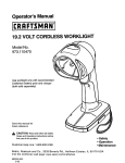
1
Operator's Manual
ERRFTSMRN'I
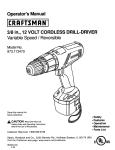
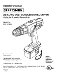
3/8 in., 19.2 VOLT CORDLESS DRILL-DRIVER
Variable Speed / Reversible
Model No.
973.114170
Save this manual for
future reference
• Safety
• Features
_, CAUTION:
Read and follow all
Safety Rules and Operating Instructions
before first use of this product.
Customer
Help Line: 1-800-932-3188
Sears, Roebuck and Co., 3333 Beverly Rd., Hoffman
Visit the Craftsman web page: www.sears.com/craftsman
983000-142
8-02
• Operation
• Maintenance
• Parts List
Estates,
IL 60179
USA
•
Table Of Contents ..........................................................................................................................................................
2
•
Warranty .........................................................................................................................................................................
2
•
Introduction .....................................................................................................................................................................
3
•
General Safety Rules, Specific Safety Rules, And Symbols .....................................................................................
•
Product Specifications ....................................................................................................................................................
•
Features .....................................................................................................................................................................
7-8
•
Operation ..................................................................................................................................................................
9-14
•
Maintenance .................................................................................................................................................................
15
•
Accessories
15
•
Exploded View And Repair Parts List ..........................................................................................................................
17
•
Parts Ordering / Service ...............................................................................................................................................
18
3-6
7
..................................................................................................................................................................
FULL ONE YEAR WARRANTY
ON CRAFTSMAN
3/8 in. CORDLESS DRILL-DRIVER
If this CRIIFTSMIIN 3/8 in. Cordless Drill-Driver fails to give complete satisfaction within one year from the date of purchase, RETURN IT TO THE NEAREST SEARS STORE OR SEARS SERVICE CENTER IN THE UNITED STATES,
and Sears will repair it, free of charge.
If this £RAFTSMAN 3/8 in. Cordless Drill-Driver is used for commercial
90 days from the date of purchase.
or rental purposes, this warranty applies for only
This warranty gives you specific legal rights, and you may also have other rights which vary from state to state.
Sears, Roebuck and Co., Dept. 817WA, Hoffman Estates, IL 60179
,_
Look for this symbol to point out important safety precautions. It means attention!!! Your safety is
involved.
_,WARNING:
The operation of any power tool can result in foreign objects being thrown into your eyes, which can
result in severe eye damage. Before beginning power tool operation, always wear safety goggles or
safety glasses with side shields and a full face shield when needed. We recommend Wide Vision
Safety Mask for use over eyeglasses or standard safety glasses with side shields, available at Sears
Retail Stores. Always wear eye protection which is marked to comply with ANSI Z87.1.
rSAFETY AND INTERNATIONAL
SYMBOLS
This operator's manual describes safety and international symbols and pictographs that may appear on this product.
Read the operator's manual for complete safety, assembly, operating and maintenance, and repair information.
MEANING
Do not expose to rain or use in damp locations,
2
Your drill-driver has many features for making your drilling
operations more pleasant and enjoyable. Safety,
performance and dependability have been given top
priority in the design of this drill-driver making it easy to
maintain and operate.
_,
Personal Safety
_WARNING:
Read and understand all instructions.
Failure to follow all instructions listed below, may
result in electric shock, fire and/or serious personal
injury.
SAVE THESE
•
•
Keep your work area clean and well lit. Cluttered
benches and dark areas invite accidents.
•
Do not operate power tools in explosive atmospheres, such as In the presence of flammable
liquids, gases, or dust. Power tools create sparks
which may ignite the dust or fumes.
•
•
Dress properly. Do not wear loose clothing or
jewelry. Contain long hair. Keep your hair, clothing,
and gloves away from moving parts. Loose clothes,
jewelry, or long hair can be caught in moving parts.
•
Avoid accidental starting. Be sure switch is in the
locked or off position before inserting battery
pack. Carrying tools with your finger on the switch or
inserting the battery pack into a tool with the switch on,
invites accidents.
Remove adjusting keys or wrenches before turning the tool on. A wrench or a key that is left attached
to a rotating part of the tool may result in personal
injury.
Safety
Do not abuse the cord. Never use the cord to carry
the charger. Keep cord away from heat, oil, sharp
edges, or moving parts. Replace damaged cords
immediately. Damaged cords may create a fire.
A battery operated tool with integral batteries or a
separate battery pack must be recharged only with
the specified charger for the battery. A charger that
may be suitable for one type of battery may create a
risk of fire when used with another battery. Use battery
only with charger listed.
MODEL
973.114170
•
•
Keep bystanders, children, and visitors away while
operating a power tool. Distractions can cause you
to lose control.
Electrical
BATTERY PACK
Item No. _ 11375
(1323513 or 1310715)
Stay alert, watch what you are doing and use
common sense when operating a power tool. Do
not use tool while tired or under the influence ef
drugs, alcohol, or medication. A moment of inattention while operating power tools may result in serious
personal injury.
INSTRUCTIONS
Work Area
•
CAUTION: Carefully read through this entire
operator's manual before using your new drill-driver.
Pay close attention to the General Safety Rules,
Specific Safety Rules and Symbols, Warnings and
Cautions. If you use your drill-driver properly and only
for it's intended use, you will enjoy years of safe,
reliable service.
CHARGER
Item No. _ 11041
(1425301)
Use battery operated tool only with specifically
designated battery pack. Use of any other batteries
may create a risk of fire. Use only with battery pack
listed.
3
•
Do not overreach. Keep proper footing and balance at all times. Proper footing and balance enables
better control of the tool in unexpected situations. Do
not use on a ladder or unstable support.
•
Use safety equipment. Always wear eye protection.
Dust mask, nonskid safety shoes, hard hat, or hearing
protection must be used for appropriate conditions.
Tool Use and Care
•
Use clamps or other practical way to secure and
support the workpiece to a stable platform. Holding
the work by hand or against your body is unstable and
may lead to loss of control.
•
Maintain tools with care. Keep cutting tools sharp
and clean. Properly maintained tools, with sharp
cutting edges are less likely to bind and are easier to
control.
•
Do not force tool. Use the correct tool for your
application. The correct tool will do the job better and
safer at the rate for which it is designed.
Do not use tool If switch does not turn It on or off.
A tool that cannot be controlled with the switch is
dangerous and must be repaired.
•
Chock for misalignment or binding of moving parts,
breakage of parts, and any other condition that may
affect the tool's operation. If damaged, have the tool
serviced before using. Many accidents are caused by
poorly maintained tools.
•
Use only accessories that are recommended by
the manufacturer for your model. Accessories that
may be suitable for one tool, may create a risk of injury
when used on another tool.
•
•
•
Disconnect battery peck from tool or place the switch
in the locked or off position before making any adjustments, changing accessories, or stodng the tool. Such
preventive safety measures reduce riskof starting the tool
accidentally.
Store Idle tools out of reach of children and other
untrained persons. Tools are dangerous in the hands
of untrained users.
Service
Tool service must be performed only by qualified
repair personnel. Service or maintenance performed
by unqualified personnel could result in a risk of injury.
When servicing a tool, use only identical replacement parts. Follow instructions In the Maintenance
section of this manual. Use of unauthorized parts or
failure to follow Maintenance Instructions may create a
risk of shock or injury.
When battery pack is not in use, keep it away from
other metal objects like: paper clips, coins, keys,
nails, screws, or other small metal objects that can
make a connection from one terminal to another.
Shorting the battery terminals together may cause
sparks, burns, or a fire.
Hold tool by insulated gripping surfaces when performing an operation where the cutting tool may contact hidden
wiring. Contact with a "live" wire will make exposed metal parts of the tool "live" and shock the operator.
Additional
•
Rules For Safe Operation
fire or heat. This will reduce the risk of explosion and
possible injury.
Know your power tool. Read operator's manual
carefully. Learn its applications and limitations, as
well as the specific potential hazards related to
_IL
this tool. Following this rule will reduce the risk of
electric shock, fire, or serious injury.
•
Make sure your extension cord is in good cor_dition.
When using an extension cord, be sure to use one
heavy enough to carry the current your product will
draw. A wire gage size (A.W.G.) of at least 16 is
recommended for an extension cord 100 feet or less
in length. A cord exceeding 100 feet is not recommended. If in doubt, use the next heavier gage. The
smaller the gage number, the heavier the cord. An
undersized cord will cause a drop in line voltage resulting in loss of power and overheating.
Important
Rules for Battery
•
Do not charge battery tool in a damp or wet
location. Following this rule will reduce the risk of
electric shock.
•
For best results, your battery tool should be
charged in a location where the temperature is
mere than 50°F but less than 100°F. Do not store
outside or in vehicles.
•
Under extreme usage or temperature conditions,
battery leakage may occur. If liquid comes in
contact with your skin, wash immediately with
soap and water, then neutralize with lemon juice
or vinegar. If liquid gets into your eyes, flush them
with clean water for at least 10 minutes, then seek
immediate medical attention. Following this rule will
reduce the risk of serious personal injury.
Tools
•
Battery tools do not have to be plugged into an
electrical outlet; therefore, they are always in
operating condition. Be aware of possible hazards
when not using your battery tool or when changing accessories. Following this rule will reduce the
risk of electric shock, fire, or serious personal injury.
•
Do not place battery tools or their batteries near
4
WARNING:
Batteries vent hydrogen gas and can
explode in the presence of a source of ignition, such
as a pilot light. To reduce the risk of serious personal
injury, never use any cordless product in the presence of open flame. An exploded battery can propel
debris and chemicals. If exposed, flush with water
immediately.
,_
WARNING:
Never use a battery that has been
dropped or received a sharp blow. A damaged battery
is subject to explosion. Properly dispose of a dropped
battery immediately. Failure to heed this warning can
result in serious personal injury.
•
Save these instructions. This manual contains
•
Do not operate charger with a damaged cord or
plug. If damaged, have replaced immediately by a
qualified serviceman. Following this rule will reduce the
risk of electric shock,fire, or sedous personal injury.
•
Do not operate charger if It has received a sharp
blow, been dropped, or otherwise damaged in any
way; take it to a qualified serviceman. Following
this rule will reduce the risk of electric shock, fire, or
serious personal injury.
•
Do not disassemble charger; take it to a qualified
serviceman when service or repair Is required.
Incorrect reassembly may result in a risk of
electric shock or fire. Following this rule will reduce
the risk of electric shock, fire, or serious personal
injury.
•
To reduce the risk of electric shock, unplug
charger from outlet before attempting any maintenance or cleaning. Turning off controls will not
reduce this risk. Following this rule will reduce the
risk of electric shock, fire, or serious personal injury.
important safety and operating instructions for
charger. Following this rule will reduce the risk of
electric shock, fire, or serious personal injury.
•
Before using battery charger, read all instructions
and cautionary markings in this manual, on
battery charger, and product using battery
charger. Following this rule will reduce the risk of
electric shock, fire, or serious personal injury.
_
CAUTION: To reduce risk of injury, charge only
nickel-cadmium and nickel metal hydride type
rechargeable batteries. Other types of batteries
may burst causing personal injury and damage.
Following this rule will reduce the risk of electric
shock, fire, or serious personal injury.
•
Do not expose charger to rain or snow. Following
this rule will reduce the risk of electric shock, fire, or
serious personal injury.
•
Do not use charger outdoors. Following this rule will
reduce the risk of electric shock, fire, or serious
personal injury.
•
Use of an attachment not recommended or sold
by the battery charger manufacturer may result in
a risk of fire, electric shock, or injury to persons.
Following this rule will reduce the risk of electric
shock, fire, or serious personal injury.
•
Disconnect charger from power supply when not
in use. Following this rule will reduce the risk of
electric shock, fire, or serious personal injury.
•
•
•
_i,
To reduce risk of damage to charger body and
cord, pull by charger plug rather than cord when
disconnecting charger. Following this rule will
reduce the risk of electric shock, fire, or serious
personal injury.
Save these instructions. Refer to them frequently
and use them to instruct others who may use this
tool. if you loan someone this tool, loan them
these instructions also. Following this rule will
reduce the risk of electric shock, fire, or serious
personal injury.
Make sure cord is located so that it will not be
stepped on, tripped over, or otherwise subjected
to damage or stress. Following this rule will reduce
the risk of serious personal injury.
An extension cord should not be used unless
_i
absolutely necessary. Use of improper extension
cord could result in a risk of fire and electric shock. If
extension cord must be used, make sure:
a. That pins on plug of extension cord are the
same number, size and shape as those of
plug on charger.
b. That extension cord is properly wired and in
good electrical condition; and
50'
100'
Cord Size (AWG)
16
16
16
WARNING:
Some dust created by power sanding,
sawing, grinding, drilling, and other construction
activities contains chemicals known to cause
cancer, birth defects or other reproductive harm.
Some examples of these chemicals are:
• lead from lead-based paints,
• crystalline silica from bricks and cement
and other masonry products, and
• arsenic and chromium from chemicallytreated lumber.
Your risk from these exposures varies, depending
on how often you do this type of work. To reduce
your exposure to these chemicals: work in a well
ventilated area, and work with approved safety
equipment, such as those dust masks that are
specially designed to filter out microscopic particles.
c. That wire size is large enough for AC ampere
rating of charger as specified below:
Cord Length (Feet) 25'
DANGER: RISK OF ELECTRIC SHOCK. DO NOT
TOUCH UNINSULATED PORTION OF OUTPUT
CONNECTOR OR UNINSULATED BA'I-rERY
TERMINAL.
Note: AWG = American Wire Gage
SAVE THESE INSTRUCTIONS
5
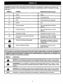
Important" Some of the following symbols may be used on your tool. Please study them and learn their meaning. Proper
interpretation of these symbols will allow you to operate the tool better and safer.
SYMBOL
NAME
DESIGNATION/EXPLANATION
V
Volts
Voltage
A
Amperes
Current
Hz
Hertz
Frequency (cycles per second)
min
Minutes
Time
Alternating Current
Type or a characteristic of current
--=--
Direct Current
Type or a characteristic of current
no
No Load Speed
Rotational speed, at no load
.../min
Revolutions or Reciprocation Per Minute
Revolutions, strokes,
surface speed, orbits etc. per minute
,_
Safety Alert Symbol
Indicates danger, warning or caution.
It means attentionrH Your safety is
involved.
Wet Conditions Alert
Do not expose to rain or use in damp
locations.
The purpose of safety symbols is to attract your attention to possible dangers. The safety symbols, and
the explanations with them, deserve your careful attention and understanding. The safety warnings do
not by themselves eliminate any danger. The instructions or warnings they give are not substitutes for
proper accident prevention measures.
SYMBOL
A
A
A
NOTE:
MEANING
DANGER: Failure to obey a safety warning will result in serious injury to yourself or to others.
Always follow the safety precautions to reduce the risk of fire, electric shock and personal injury.
WARNING:
Failure to obey a safety warning can result in serious injury to yourself or to others.
Always follow the safety precautions to reduce the risk of fire, electric shock and personal injury.
CAUTION: Failure to obey a safety warning may result in property damage or personal injury to
yourself or to others. Always follow the safety precautions to reduce the risk of fire, electric shock
and personal injury.
Advises you of information or instructions vital to the operation or maintenance of the equipment.
6
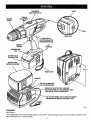
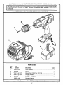
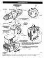
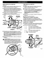
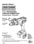
DRILL-DRIVER
Chuck
Motor
973.114170
DC Motor 19.2 Volt
Rating
12o V, 60 Hz, AC only
GearTrain
NoLoadSpeed
Two Speed
Charging Voltage
7.2 - 24 Volt
0-400 RPM (Low)
0-1400 RPM (High)
Charge Rate
1 Hour
BATTERY
Item No. 9 11375
Clutch
24 Positions
Maximum Torque
400 in.lbs
KNOW
YOUR
CHARGER
Item No. 9 11041
3/8 in. Keyless
(1425301)
PACK
(1323513
DRILL-DRIVER
FORWARD/REVERSE
or 1310715)
SELECTOR
See Figure 1.
(DIRECTION
Before attempting to use your drill-driver, familiarize
yourself with all operating features and safety
requirements.
Your drill-driver has a forward/reverse selector located
KEYLESS
above the switch trigger.
WRIST
CHUCK
SWITCH
BIT STORAGE
To turn your drill-driver ON, depress the switch trigger.
Release switch trigger to turn your drill-driver OFF.
When not in use, bits provided with your drill-driver can be
placed in the storage area located on the bottom of the
motor housing.
LOCK
LEVEL
The switch trigger can be locked in the OFF position. This
feature helps reduce the possibility of accidental starting
when not in use.
VARIABLE
To keep drill bit level during drilling operations, a level is
located on the top and end of the motor housing.
SPEED
,_
This tool has a variable speed switch that delivers higher
speed with increased trigger pressure. Speed is controlled
by the amount of switch trigger depression.
TWO
STRAP
A wrist strap is provided to reduce the chances of
dropping your drill-driver. Place one hand through the wrist
strap when carrying tool.
Your drill-driverhas a keyless chuck that allows you to hand
tighten or release drill bit in the chuck jaws.
SWITCH
OF ROTATION SELECTOR)
SPEED
GEAR TRAIN
Your drill-driver has a two speed gear train designed for
drilling or driving at HI or LO speeds. A slide switch is
located on top of your drill to select either HI or LO speed.
7
WARNING: If any parts are missing, do not operate
your drill-driveruntil the missing parts are replaced.
Failure to do so could result in possible serious
personal injury.
TWO-SPEED
GEARTRAIN(HI-LO)
LEVEL
TORQUE
ADJUSTMENT
RING
KEYLESS
CHUCK
REARVIEW
DIRECTIONOF
ROTATIONSELECTOR
(FORWARD/REVERSE)
SWITCH
TRIGGER
BIT
STORAGE
SCREWDRIVER
BITS
BATTERYPACK
SHOWNINTOOL
BAI"I'ERYPACK
SHOWNINCHARGER
4-1/2 in.
WRISTSTRAP
CHARGER
RED LED ONINDICATES
MODE
GREENLEDONAFTERFASTCHARGING
CYCLE,INDICATESFULLYCHARGEDBATTERY
PACKANDIN TRICKLECHARGEMODE.
YELLOWANDGREENLEDSONINDICATESDEEPLY
DISCHARGEDOR DEFECTIVEBATTERYPACK.
Fig. 1
CHARGER
See Figure 1.
Your charger has a "key hole" hanging feature for convenient, space saving storage. Screws should be instalred so that
center distances are 4-1/2 inches apart,
8
_
WARNING:
Do not allow familiarity with your drilldriver to make you careless. Remember that a
careless fraction of a second is sufficient to inflict
severe injury.
LED FUNCTIONS
LED WILL
CHARGER
Note: Batteries will not reach full charge the first time they
are charged. Allow several cycles (drilling followed by
recharging) for them to become fully charged.
CHARGING
BA'n'ERY
PACK
See Figure 1.
•
Charge battery pack only with the charger provided.
•
Make sure power supply is normal household
voltage, 120 volts, 60 Hz, AC only.
•
Connect charger to power supply.
•
Place battery pack in charger aligning raised rib on
battery pack with groove in charger. See Figure 1.
•
Press down on battery pack to be sure contacts on
battery pack engage properly with contacts in charger.
•
Normally, the red LED on charger wilt come on. This
indicates charger is in fast charging mode.
•
Red LED should remain on for approximately 1 hour
then the green LED will come on. Green LED on
indicates battery pack is fully charged and charger is in
trickle charge mode. Note: Green LED will remain on
until battery pack is removed from charger or charger
is disconnected from power supply.
•
If both yellow and green LED come on, this indicates a
deeply discharged or defective battery pack.
Allow battery pack to remain in charger for 15 to 30
minutes. When battery pack reaches normal voltage
range, red LED should come on.
If red LED does not come on after 30 minutes, this
indicates a defective battery pack and should be
replaced.
•
After normal usage, a minimum of 1 hour of charging
time is required to fully recharge battery pack.
•
The battery pack will become slightly warm to the
touch while charging. This is normal and does not
indicate a problem.
Do not place charger and battery pack in an area of
extreme heat or cold. It will work best at normal room
temperature.
Note: Charger and battery pack should be placed in a
location where the temperature is more than 50°F but
less than 10O°F.
When batteries become fully charged, unplug charger
from power supply and remove the battery pack.
OF
Red LED on = Fast charging mode.
BA'n'ERY PACK
The battery pack for your tool has been shipped in a low
charge condition to prevent possible problems. Therefore,
you should charge it until light on front of charger changes
from red to green.
OF CHARGER
BE ON TO INDICATE STATUS
AND BATTERY PACK:
Green LED on = Fully charged and in trickle charge
mode.
•
Green LED on = When battery pack is inserted into
charger, indicates hot battery pack or that battery pack
is out of or below normal temperature range.
•
Yellow and Green LEDs on = Deeply discharged or
defective battery pack.
•
No LED on = Defective charger or battery pack.
_i,
CAUTION: To prevent damage to battery pack,
remove battery pack from charger immediately if no
LED comes on. Return battery pack and charger to
your nearest Sears Service Center for checking or
replacing. Also, if you are removing battery pack from
charger and no LEDs are on, return both battery pack
and charger to your nearest Sears Service Center.
Do not insert another battery pack into charger. A
damaged charger may damage a battery pack.
IMPORTANT
INFORMATION
HOT BATTERY PACK
FOR RECHARGING
When using your drill-driver continuously, the batteries in
your battery pack will become hot. You should let a hot
battery pack cool down for approximately 30 minutes
before attempting to recharge. When the battery pack
becomes discharged and is hot, this will cause the green
LED to come on instead of the red LED. After 30 minutes,
reinsert battery pack in charger. If green LED continues to
remain on, return battery pack to your nearest Sears
Repair Center for checking or replacing.
Note: This situation only occurs when continuous use of
your drill causes the batteries to become hot. It does not
occur under normal circumstances. Refer to "CHARGING
BA'B'ERY PACK" for normal recharging of batteries. If
the charger does not charge your battery pack under
normal circumstances, return both the battery pack and
charger to your nearest Sears Repair Center for electrical
check.
IMPORTANT
INFORMATION
COOL BATTERY PACK
FOR RECHARGING
If battery pack is below normal temperature range, the
green LED on charger will come on. Allow battery pack to
reach normal temperature, then the red LED will come on.
Note: Refer to "CHARGING BATrERY PACK" for
normal recharging of batteries. If the charger does not
charge your battery pack under normal circumstances,
return both the battery pack and charger to your nearest
Sears Repair Center for electrical check.
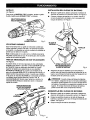
SWITCH
TO INSTALL BA'I-rERY PACK
See Figure 2.
•
To turn your drill ON, depress the switch trigger. To turn it
OFF, release the switch trigger.
Lock switch trigger on your drill by placing the direction
of rotation selector in center position. See Figure 5.
•
Place battery pack in your drill. Align raised rib on
battery pack with groove inside drill. See Figure 4.
FORWARD/REVERSE
SWITCHTRIGGER
VARIABLE
BATTERY
PACK
Fig. 2
SPEED
LATCHES
This tool has a variable speed switch that delivers higher
speed and torque with increased trigger pressure. Speed is
controlled by the amount of switch trigger depression.
Note: You might hear a whistling or ringing noise from the
switch during use. Do not be concerned, this is a normal
part of the switch function.
"I3NO-SPEED
\
GEAR TRAIN
See Figure 3.
Your drill has a two-speed gear train designed for drilling
or driving at LO (1) or HI (2) speeds. A slide switch is
located on top of your drill to select either LO (1) or HI (2)
speed. When using drill in the LO (1) speed range, speed
will decrease and unit will have more power and torque.
When using drill in the HI (2) speed range, speed will
increase and unit will have less power and torque. Use
LO (1) speed for high power and torque applications and
HI (2) speed for fast drilling or driving applications.
TWOSPEED
GEARTRAIN(HI.LO)
•
_IL
L(_
SPEED
DEPRESSLATCHESTO
RELEASEBATTERYPACK
Make sure the latches on each side of your battery
pack snap in place and battery pack is secured in drill
before beginning operation.
CAUTION: When placing battery pack in your drill,
be sure raised rib on battery pack aligns with groove
inside drill and latches snap into place properly.
Improper assembly of battery pack can cause
damage to internal components.
TO REMOVE
HI
SPEED
Fig. 3
10
Fig. 4
BATTERY
PACK
•
Lock switch trigger on your drill by placing the direction
of rotation selector in center position. See Figure 5.
•
Locate latches on side of battery pack and depress to
release battery pack from your drill. See Figure 4.
•
Remove battery pack from your drill.
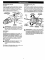
SWITCH
KEYLESS CHUCK
LOCK
See Figure 5.
See Figure 6.
The switch trigger can be locked in the OFF position. This
feature can be used to prevent the possibility of accidental
starting when not in use. To lock switch trigger, place the
direction of rotation selector (Forward/Reverse Selector)
in center position. Note: When selector is in center
position, switch trigger is locked.
Your drill has a keyless chuck, As the name implies, you can
hand tighten or release drill bits in the chuck jaws. Grasp and
hold the collar of the chuck with one hand. Rotate the chuck
body with your other hand. The arrows on the chuck
indicate which direction to rotate the chuck body in order to
LOCK (tighten) or UNLOCK (release) the drill bit.
SELECTORWITH
REVERSe"
UNLOCK
_''"==_
CHUCK
COLLAR
CHUCKJAWS
FORWARD
Fig. 5
_1= WARNING:
Battery tools are always in operating
condition. Therefore, switch should always be locked
when not in use or carrying at your side.
CHUCK
(TIGHTEN)
BODY
Fig. 6
_i
REVERSIBLE
See Figure 5.
This tool has the feature of being reversible. The direction
of rotation is controlled by a selector located above the
switch trigger. With the drill held in normal operating
position, the direction of rotation selector should be
positioned to the left of the switch for drilling. The drilling
direction is reversed when the selector is to the right of
the switch. When the selector is in center position, the
switch trigger is locked.
_L
LOCK
CAUTION: To prevent gear damage, always allow
chuck to come to a complete stop before changing
the direction of rotation.
To stop, release switch trigger and allow the chuck to come
to a complete stop.
11
WARNING:
Do not hold chuck body with one hand
and use power of the drill to tighten chuck jaws on
drill bit. Chuck body could slip in your hand or your
hand could slip and come in contact with rotating drill
bit. This could cause an accident resulting in serious
personal injury.
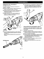
INSTALLINGBITS
REMOVING BITS
See Figure 7.
See Figure 7.
Lock the switch trigger by placing the direction of
rotation selector in center position. See Figure 5.
Lock the switch trigger by placing the direction of
rotation selector in center position. See Figure 5.
Open or close chuck jaws to a point where the opening ts slightly larger than the bit size you intend to use.
Also, raise the front of your drill slightly to keep the bit
from falling out of the chuck jaws.
Loosen the chuck jaws from drill bit.
Z
To loosen: grasp and hold the collar of the chuck with
one hand, while rotating chuck body with your other
hand. Note: Rotate chuck body in the direction of the
arrow marked UNLOCK to loosen chuck jaws.
Insert drill bit straight into chuck the full length of the
jaws as shown in Figure 7.
Do not use a wrench to tighten or loosen the chuck
jaws.
Tighten the chuck jaws on drill bit.
DRILLBIT
UNLOCK
CHUCK
(RELEASE)
COLLAR
Remove drill bit from chuck jaws.
ADJUSTABLE
TORQUE CLUTCH
I
Your drill is equipped with an adjustable torque clutch for
dri
driving
different types of screws into different materials.
TI- proper setting depends on the type of material and the
The
size of screw you are using.
--
T( ADJUST
TO
TORQUE
Identify the twenty four torque indicator settings located
on the front of your drill. See Figure 9.
Rotate adjusting ring to the desired setting.
CHUCKJAWS
• 1-4
LOCK
(TIGHTEN)
RIGHT
•
•
_
CHUCK
BODY
5-8
_
f_rrz_,Y-....
For driving screws into soft and hard
materials.
• 13 - 16
For driving screws in hard wood.
• 17-
For driving large screws.
20
• 21 - ,11
Note= Rotate the chuck body in the direction of the
arrow marked LOCK to tighten chuck jaws.
Do not use a wrench to tighten or loosen the chuck
jaws.
For driving screws into soft
material
• 9-12
Fig. 7
To tighten the chuck jaws on drill bit; grasp and hold
the collar of the chuck with one hand, while rotating
the chuck body with your other hand.
For driving small screws.
For heavy drilling.
TO DECREASE
TORQUE
ADJUSTING
RING
WARNING:
Make sure to insert drill bit straight into
chuck jaws. Do not insert drill bit into chuck jaws at
an angle then tighten, as shown in Figure 8. This
could cause drill bit to be thrown from drill, resulting
in possible serious personal injury or damage to the
chuck.
TOINCREASE
TORQUE
Fig. 8
12
Fig. 9
BIT STORAGE
DRILLING
See Figure 10.
See Figure 12.
When not in use, bits provided with your drill can be
placed in the storage area located on the bottom of your
drill as shown in Figure 10.
LEVEL
SCREWDRIVER
BIT
STORAGEAREA
,_
Fig. lO
WARNING: Always wear safety goggles or safety
glasses with side shields when operating tools.
Failure to do so could result in objects being thrown
into your eyes, resulting in possible serious injury.
LEVEL
Fig. 12
See Figure 11.
When drilling hard smooth surfaces use a center punch to
mark desired hole location. This will prevent the drill bit
from slipping off center as the hole is started. However,
the low speed feature allows starting holes without center
punching if desired. To accomplish this, simply operate
your drill at a tow speed until the hole is started.
A convenient feature provided with your drill is a level. It
is recessed in the motor housing on top and end of your
drill It can be used to keep drill bit level during drilling
operations.
The material to be drilled should be secured in a vise or
with clamps to keep it from turning as the drill bit rotates.
Hold tool firmly and place the bit at the point io be drilled.
Depress the switch trigger to start tool.
Move the drill bit into the workpiece applying only enough
pressure to keep the bit cutting. Do not force or apply side
pressure to elongate a hole.
_i
WARNING:
Be prepared for binding or bit
breakthrough. When these situations occur, drill has
a tendency to grab and kick opposite to the direction
of rotation and could cause loss of control when
breaking through material. If not prepared, this loss
of control can result in possible serious injury.
When drilling metals, use a light oil on the drill bit to keep
it from overheating. The oil will prolong the life of the bit
and increase the drilling action.
If the bit jams in workpiece or if the drill stalls, release
switch trigger immediately. Remove the bit from the
workpiece and determine the reason for jamming.
Fig. 11
13
CHUCK
REMOVAL
•
See Figures 13, 14, and 15.
The chuck must be removed in order to use some
accessories. To remove:
•
Lock the switch trigger by placing the direction of
rotation selector in center position. See Figure 5.
•
Insert a 5/16 in. or larger hex key into the chuck of your
drill and tighten the chuck jaws securely.
•
Tap the hex key sharply with a mallet in a clockwise
direction. See Figure 13. This will loosen the screw in
the chuck for easy removal.
Insert hex key in chuck and tighten chuck jaws securely. Tap sharply with a mallet in a counterclockwise
direction. This will loosen chuck on the spindle. It can
now be unscrewed by hand. See Figure 15.
MALLET
MALLET
CHUCKJAWS
Fig. 15
TO RETIGHTEN
A LOOSE
CHUCK
The chuck may become loose on spindle and develop a
wobble. Periodically check chuck screw for tightness.
To tighten, follow these steps:
Fig. 13
•
Open chuck jaws and remove hex key. Remove the
chuck screw by turning it in a clockwise direction. See
Figure 14.
Note: The screw has left hand threads.
SCREWDRIVER
•
Lock the switch trigger by placing the direction of
rotation selector in center position. See Figure 5.
•
Open the chuck jaws.
•
Insert hex key into chuck and tighten chuck jaws
securely. Tap hex key sharply with a mallet in a
clockwise direction. This will tighten chuck on the
spindle.
•
Open the chuck jaws and remove hex key.
•
Tighten the chuck screw.
Note: The chuck screw has left hand threads.
Fig. 14
14
_
Do not abuse power tools. Abusive practices can
damage tool as well as workpiece.
WARNING: When servicing, use only identical
Craftsman replacement parts. Use of any other
part may create a hazard or cause product damage.
Only the parts shown on parts list, page 17, are intended
to be repaired or replaced by the customer. All other parts
should be replaced at a Sears Service Center.
Avoid using solvents when cleaning plastic parts. Most
plastics are susceptible to damage from various types of
commercial solvents and may be damaged by their use.
Use clean cloths to remove dirt, dust, oil, grease, etc.
,_
,_
WARNING:
Do not at any time let brake fluids,
gasoline, petroleum-based products, penetrating oils,
etc. come in contact with plastic parts. They contain
chemicals that can damage, weaken or destroy
plastic.
WARNING:
Do not attempt to modify this tool or
create accessories not recommended for use with
this tool. Any such alteration or modification is
misuse and could result in a hazardous condition
leading to possible serious personal injury.
BATTERIES
Your drill's battery pack is equipped with nickel-cadmium
rechargeable batteries. Length of service from each
charging will depend on the type of work you are doing.
To preserve natural resources, please
recycle or dispose of batteries properly.
This product contains nickel-cadmium
batteries. Local, state or federal laws
may prohibit disposal of nickel-cadmium
batteries in ordinary trash.
The batteries in this tool have been designed to provide
maximum trouble free life. However, like all batteries, they
will eventually wear out. Do not disassemble battery pack
and attempt to replace the batteries. Handling of these
batteries, especially when wearing rings and jewelry,
could result in a serious burn.
Consult your local waste authority for information
regarding available recycling and/or disposal options.
BATTERY PACK
FOR RECYCLING
To obtain the longest possible battery life, we suggest the
following:
•
•
Store and charge your batteries in a cool area.
Temperatures above or below normal room
temperature wilt shorten battery life.
,_
Never store batteries in a discharged condition.
Recharge them immediately after they are
discharged.
All batteries gradually lose their charge. The higher
the temperature the quicker they lose their charge. If
you store your tool for long periods of time without
using it, recharge the batteries every month or two.
This practice will prolong battery life.
The following recommended
REMOVAL
AND PREPARATION
WARNING:
Upon removal, cover the battery pack's
terminals with heavy duty adhesive tape. Do not
attempt to destroy or disassemble battery pack or
remove any of its components. Nickel-cadmium
batteries must be recycled or disposed of properly.
Also, never touch both terminals with metal objects
and/or body parts as short circuit may result. Keep
away from children. Failure to comply with these
warnings could result in fire and/or serious injury.
accessories are currently available at Sears Retail Stores.
•
6-Pc. Extra Length Magnite Power Bit Set
•
17-Pc. Power Screwdriver/Nutdriver
•
30-Pc. Power Screwdriver/Nutdriver
•
High Speed Bits (For Wood or Metal)..3/4 in. Max.
_ll, WARNING:
Set and Case
The use of attachments or accessories not listed might be hazardous.
15
Set and Case
16
CRAFTSMAN
3/8 in., 19.2 VOLT CORDLESS
DRILL-DRIVER
- MODEL
NO. 973.114170
in all correspondence regarding your 3/8 in., 19.2 VOLT CORDLESS DRILL-DRIVER or when ordering
The
repairmodel
parts.number will be found on a plate attached to the motor housing. Always mention the model number
SEE BACK PAGE FOR PARTS ORDERING INSTRUCTIONS
2
4
3
PARTS LIST
Key
No.
Part
Number
1
616478-003
Screw (Special) ......................................................................
1
2
6903330
Chuck .....................................................................................
1
Description
Quan.
3
*Item No. 9 11375
Battery Pack (1323513 or 1310715) ......................................
1
4
*Item No. 9 11041
Charger (1425301 ) .................................................................
1
9021107
Tool Bag - Not Shown ...........................................................
1
983000-142
Operator's Manual
5
* Can Be Purchased Thru RSOS (Retail Special Order System)
•
i
17
Your Home
For repair-in
your home-of all major brand appliances,
lawn and garden equipment, or heating and cooling systems,
no matter who made it, no matter who sold it!
For the replacement parts, accessories and
owner's manuals that you need to do-it-yourself.
For Sears professional installation of home appliances
and items like garage door openers and water heaters.
1-800-4-MY-HOME
Call anytime,
® (1-800-469-4663)
day or night (U.S.A. and Canada)
www.sears.com
Our
www.sears.ca
Home
For repair of carry-in items like vacuums, lawn equipment,
and electronics, call or go on-line for the location of your nearest
Sears Parts & Repair Center.
1-800-488-1222
Call anytime,
day or night (U.S.A. only)
www.sears.com
To purchase a protection agreement on a product serviced by Sears:
1-800-827-6655
(U.S.A.)
Para pedir servicio de reparaci6n
y para ordenar piezas:
1-888-SU-HOGAR _
a domicilio,
(1-888-784-6427)
1-800-361-6665
(Canada
Au Canada pour service en frangals:
1-800-LE-FOYER
"c
(1-800-533-S937)
www.sears.ca
® Registered Trademark / TMTrademark / SMService Mark of Seam, Roebuck and Co.
® Marca Registrada / TMMarca de F&brica/ sMMarca de Servicio de Seam, Roebuck and Co.
McMarque de commerce / MOMarque d6posde de Sears, Roebuck and Co.
O Seem, Roebuck and Co.
Manual del Usuario
II:RRFTSMRN1
TALADRO/DESTORNILLADOR A
BATERIA de 3/8 pulg., 19.2 VOLTIOS
VelocidadVariable / Reversible
No. de Modelo
973.114170
Conserve
este manual
para referencia
_,
• Seguridad
• Caracteristicas
• Funcionamiento
• Mantenimiento
• Lista de
Repuestos
futura
ATENClON"
Lea cuidadosamente
todas
las Reglas de Seguridad y las Instrucciones
antes de usar esta herramienta.
No. de tel_fono
de ayuda a los clientes:
1-800-932-3188
Sears, Roebuck and Co., 3333 Beverly Rd., Hoffman
Visite la p_.gina Web de Craftsman: www.sears.com/craftsman
983000-142
8-02
Estates,
IL 60179
USA
0( us
•
Tabla de Materias ............................................................................................................................................................
2
•
Garantia ...........................................................................................................................................................................
2
•
Introduccibn .....................................................................................................................................................................
3
•
Reglas de Seguridad Generales, Reglas de Seguridad Especificas y Sfmbolos ......................................................
•
Especificaciones
•
Caractedsticas
............................................................................................................................................................
•
Funcionamiento
.........................................................................................................................................................
•
Mantenimiento
..............................................................................................................................................................
15
•
Accesorios ....................................................................................................................................................................
15
•
Vista Esquem&tica y Lista de Repuestos .....................................................................................................................
17
•
Pedidos de Repuestos/Servicio
18
3-6
del Producto .......................................................................................................................................
7
7-8
9-14
...................................................................................................................................
GARANTIA COMPLETA DE UN AI_IO DEL TALADRO/DESTORNILLADOR
A BATERIA CRAFTSMAN
DE 3/8 pulg.
Si este Taladro/Destomillador a Bateria rRRFTSHRH de 3/8 pulg. no le proporciona completa satisfacci6n a partir de un
aSo desde la fecha de compra, DEVUE/VALO A/ALMACEN
SEARS MAS CERCANO EN LOS ESTADOS UNIDOS y
Sears Io reemptazar& gratuitamente.
Si este Taladro/Destornillador a Bateria CRRFTSNliH de 3/8 pulg. se usa para prop6sitos comerciales o de alquiler, esta
garantia es v&lida solamente durante 90 dfas desde la fecha de compra.
Esta garantia le otorga derechos legales especificos y usted puede adem&s tener otros derechos que varfan de un
estado a otro.
Sears, Roebuck and Co., Dept. 817 WA, Hoffman Estates, IL 60179
Este simbolo le indica importantes reglas de seguridad, iSignifica atencibn! Existe riesgo para su
seguridad.
_1= ADVERTENCIA:
La utilizacibn de cualquier herramienta mec_nica puede causar la proyeccibn de objetos extrahos a
sus ojos, Io cual puede ocasionar daSos oculares severos. Antes de comenzar a usar la herramienta
mec&nica, siempre use sus lentes protectores o gafas de seguridad con proteccibn lateral y una
mascara completa cuando sea necesario. Recomendames una Mascara de Visibn Amplia para usar
sobre sus lentes protectores o lentes de seguridad est&ndar, con protecci6n lateral, disponible en los
Almacenes Sears. Siempre use proteccion para los ojos que cumpla con la norma ANSI Z87.1.
SIMBOLOS
DE SEGURIDAD
E INTERNACIONALES
En este manual del usuario se describen los simbolos de seguridad e internacionales y pictogramas que puedan aparecer
en este producto. Lea este manual para obtener informaci6n completa sobre seguridad, montaje, funcionamiento,
mantenimiento y reparacibn.
SIGNIFICADO
No exponga a la Iluvia ni use en lugares h6medos.
2
Sutaladro/destornillador
tienemuchas
caracteristicas
que
contribuyen
afacilitary hacermasagradable
sutrabajo.Seha
dadoprioridad
m&xima
a laseguridad,
rendimiento
y
dependabilidad
enel diseho de este taladro/destornillador por
_k
Io cual es f_cil de mantener y operar.
,_
ADVERTENClA:
Lea y comprenda todas las
Instrucciones. El incumplimientode todas las
instruccionessiguientes pueden producirun choque
el_ctrico,incendioy/o lesiones personalesgraves.
CONSERVE
ESTAS INSTRUCCIONES
Lugar de Trabajo
•
Mantenga el lugar de trabajo limp|o y bien iluminado.
Los bancos de trabajo desordenados y la falta de
iluminaci6nfavorecen los accidentes.
• No utilice las herramientas electricas en una atmdsfera
explosiva, tal como en presencia de I|quidos
inflamables, gases o polvo. Las herramientasel_ctricas
crean chispasque pueden inflamar el polvoo los vapores.
• Mantenge a los espectadores, nifios o vieltantes a una
distancla prudente cuando estd utilizando una
herramlenta el6ctrica. Las distraccionespueden hacerle
perder el control.
Seguridad EI6ctrica
•
•
•
No abuse del cordbn eldctrico. Nunca transporte el
cargador sujetdndolo del cordbn. Mantenga el cordbn
ale|ado del calor, del acelte, hordes afilados o plezas
m6viles. Reemplace inmediatarnente los eordones
el6ctrlcos que estdn dafiados. Los cordonesdahados
pueden crear un incendio.
Una herramienta que utilice bater|as, ya sea con
baterlas integrales o un bloque de baterias separado,
debe ser cargado selamente con el cargedor
especiflcado para la bateria. Un cargadorque puede ser
adecuado para un tipode baterfa puede crear un peligrode
incendiocuando se usa con otra bateria. Use la bateria
correspondienteal cargadorque se indica.
MODELO
BLOQUE DE BATERIAS
CARGADOR
973.114170 Art. No. 9 11375
Art. No. 9 11041
(1323513 o 1310715)
(1425301)
Use le herramienta a beterla solamente con el bloque de
baterias especlficamente deslgnado. El uso de cualquiera
otra bateria puede crear un peligrode incendio.Use
solamente con el bloquede baterias indicado.
ATENCION:
Lea cuidadosamentetodo este manual
antes de usar su nuevo taladro/destomillador.Preste
mucha atenci6nalas Reglas de SeguridadGenerales/
Simbolos, asi como alas Advertenciasy Avisos. Si usted
utilizael taladro/destornilladordebidamentey solamente
para el propbsitoque ha sidodisehado, usteddisfrutar&
de muchosahos de servicio seguro.
Seguridad
Personal
• Mantdngase alerta, observe Io que estd haciendo y use
sentido comun cuando este cansado o bajo la influencia
de drogas, alcohol o medicinas, Un memento de
distracci6n cuando est& trabajandocon las herramientas
e ectncas, puede ocasionar una lesi6n personal grave.
• Use vestimenta adecuada. No use ropas sueltas o
joyas. Atese el cabello largo. Mantenga su cabello,
ropas y guantes alejados de las piezas mbviles. Las
ropas sueltas, las joyas o el cabello largo pueden quedar
atrapados en las piezas mbviles.
• Evite la puesta en marcha accidental• Asegurese de que
el interruptor est_ en la posicibn "OFF" (Apagado) o
bloqueado antes de insertar el bloque de bater|as. Si
transporta su herramienta con el dedo en el interruptoro si
inserta el bloque de baterias en una herramienta con el
interruptor en la posicibn "ON" (Encendido), puede causar
un accidente.
•
•
Saque las Ilaves de ajuste o Ilaves inglesas antes de
poner en marcha la herramienta. Si se deja una Ilave
inglesao una Ilave de ajuste en una pieza mbvilo en una
pieza giratoriade la herramienta,se puede produciruna
lesibnpersonal.
No use la herramienta a una distancla demasiado
alejada. Mantenga siempre un buen equilibrio y una
posici0n flrme. El buen equilibrioy la posicibnfirme
permitenun mejorcontrolde la herramientaen situaciones
imprevistas. No la utilieeen una escalera o en un apoyo
inestable.
• Use equipo de seguridad. Use siempre lentes
protectores. Se debe usar m_scara contra el polvo,
zapatosde seguridadantirresbaladizos,casco de seguridad
o proteccibnauditivade acuerdo con las circunstancias.
Uso
•
•
•
•
•
•
•
y Cuidado
de las Herramientas
Use prensas u otto m_todo prdctico para asegurar y
apoyar la pieza de trabajo en una plataforma estable, Si
sujeta el trabajo con la mano o contra su cuerpo queda
inestable y puede conducir a la p_rdida de control.
No fuerce la herramlenta. Use la herramienta apropiada
para el trabajo. La herramienta correcta har_ el trabajo
mejor y de manera mas segura, a la velocidad para la cual
fue disefiada.
No use la herramienta sl el interruptor no funciona
debldamente. Es peligroso si la herramienta no puede ser
controlada con el interruptor y per Io tanto debe set reparada.
Desconecte el bloque de baterias de la herramienta antes
de hacer algdn ajuste, cambiar accesorios o guardarla.
Estas medidas preventivas de seguridad reducen el riesgo de
que la herramienta se penga en marcha accidentalmente.
Guarde las herramientas lejos del alcance de los ninos y
de otras personas inexpertas. Las herramientas son
peligrosas en manos de personas inexpertas.
Cuando el bloque de baterfas no este en use, mantdngalo
alejado de otros objetos de metal tales como:
sujetapapeles, monedas, Ilaves, clavos, tornillos u otros
objetos metdllcos pequenos que pueden conectar un
borne con el otro. La cortocircuitacibn de los bornes de la
baterla puede causar chispas, quemaduras o un incendio.
Mantenga bien cuidadas las herramientas. Las
herramlentas oortantes deben mantenerse afiladas y
•
•
limpias. Las herramientas que se mantienen bien cuidadas y
bien afiladas tienen menos pmbabilidad de atascarse y se
pueden controlar m&s f&cilmente.
Verifique si hay piezas desalineadas o atascadas, si hay
piezas quebradas o si existe cualquier otra sltuacibn que
pueda afectar el funclonamiento
de la herramlenta. Si la
herramienta est_ da_ada, debe repararse antes del uso.
Muchos accidentes son causados debido al mal estado de las
herramientas.
Use solamente los accesorios recomendados pot el
fabricante para su modelo. Los accesorios que pueden ser
adecuados para una herramienta, pueden ser peligrosos si se
utilizan en otra.
Reparacion
•
•
La reparacibn de las herramientas debe set efectuada
solamente por personal califlcado. La reparaci6n o
mantenimiento efectuado pot personal no especiaUzado
puecle causar una lesibn personal.
Cuando efectue reparaciones en una herramlenta, use
solamente repuestos leg|tlmos. Siga las instrucciones
indicadas en la seceibn Mantenimiento de este manual. El
uso de piezas no autorizadas o el incumplimiento de las
instrucciones de mantenimiento, puede crear un riesgo de
choque el_rico o lesiones.
Sostenga la herramienta por las superficies de sujecibn aisladas cuando la herramlenta de corte pueda hacer contacto con
alambrado escondido. Si la herramienta hace contacto con un alambre bajo "tensi6n" las piezas de metal expuestas de la herramienta
tambi_n quedar_n bajo "tensibn" y pmducir_.n un choque el_ctrico para el operador.
Reglas Adicionales
para Funcionamiento
Seguro
• Conozca su herramlenta mecdnica. Lea cuidadosemente
el manual del usuarlo, Aprenda sus aplicaciones y
Ilmltaciones as| como tambidn los riesgos potenciales
especificos relaclonados con esta herramienta. Si se
cumpleesta regtase reducir_,el riesgo de un choque
el_ctrico,incendioo lesibn grave.
• Asegdrese de que su cordbn de extensibn estd en buen
estado. Cuando use un cordbn de extensibn, asegdrese
de que su didmetro sea suflciente para portar la corriente
que necesita su herramienta. Se recomienda un cordbn
de por Io menos calibre 16 (A.W.G.) para un cordbn de
extensl6n de 100 pies o menos de largo. No se
recomienda el use de un cordbn que sobrepase los
100 pies de largo. Si tiene dudas, use el sigulente calibre
de un didmetro mayor. Mientras m_,s pequetio es el
ndmero del calibre, mayor es el didmetro del cordbn. Un
cordbnde calibre inferiorcausar&una p_rdidaen el voftajede
Iinea resultandoen p6rdidade potenciay
sobrecalentamiento.
•
Reglas de Seguridad Importantes para
Herramlentas a Bater|a
•
•
I.as herramlentas a bater|a no necesitan ser enchufadas
en un tomacorrlente eldctrlco, por Io tanto slempre estdn
Iistas para ser usedas. Estd atento a los poslbles
pellgros cuando no est<_utilizando su herramlenta a
baterl'a o cuando camble accesorlos. Si se cumple esta
regla se reducir_, el riesgo de un choque el(_ctrico, incendio o
lesibn personal grave.
_ll
•
•
No coloque las herramientas a bateria o sus baterias
cerca del fuego o de una fuente de calor. Si se cumple
esta regla se reducir_ el riesgo de explosi6n y pesible lesi6n
personal
ADVERTENCIA:
Las baterias emiten hidrbgeno y
pueden explotar en presencia de una fuente de ignicibn, tal
como una luz piloto. A fin de reducir el riesgo de sufrir una
lesibn personal grave, nunca use ning6n producto a bateria
cerca de una llama abierta. Una bateria que explote puede
lanzar residuos y quimicos. Si entra en contacto con tales
materiales, I_vese inmediatamente con agua la parte
afectada.
No cargue la herramienta a bater|a en un lugar hdmedo.
Si se cumple esta regla se reducira el riesgo de un choque
el_ctrico.
Para obtener mejores resultados, su herramienta a
baterfa debe ser cargada en un lugar donde la
temperatura sea superior a 50 ° F (10 ° C) pero inferior a
100 ° F (37 ° C). No guarde en el exterior o en vehlculos.
BaJo condiciones de use o temperatura extrema, puede
ocurrir escape de Ifquldo en la baterla. SI el I_quido entra
en contacto con la plel, Idvese inmedlatamente con agua
y jabbn, luego neutralice con jugo de limbn o vlnagre. Si
entra Ifquido a sus oJos, I_velos con agua Ilmpla durante
10 minutos, luego busque atencibn m_:llca Inmedlata. Si
se cumple esta regla se reducird el riesgo de un choque
el_ctrico, incendio o lesi6n personal grave.
•
No haga funcionar el cargador sl el cordon o el
enchufe estSn da_ados. SI estdn decades, hdgalos
reemplazar inmediatamente per un electrlcista
calificado. Si se eumple esta regla se reducira el riesgo
de un cheque elOctrico,incendio o lesion personalgrave.
Conserve estas instrucclones. Este manual contiene
inetrucciones de seguridad y funclonamiento
Importantes sobre el cargador. Si se cumple esta regla
se reducira,el riesgo de un cheque electrioo, incendio o
lesion personal grave.
•
No hega funcionar el cargador si ha recibido un golpe
fuerte, si se ha caido o si ee ha dahado de alguna
manera. Lldvelo aun reparador calificado. Si se eumple
esta regla se reducira el riesgo de un cheque el_ctrieo,
incendio o lesion personal grave.
• Antes de usar el cargador de la bater|a, lea todas las
instrucciones y advertencias indicadas en este manual,
en el cargador de la bateria yen la herramienta que es
alirnentada per el cargador. Si se cumple esta regis se
reducira el riesgo de un choque el_ctrico, incendio o lesion
personal grave.
•
No desarme el cargador; Ilevelo a un t_cnico
calificado cuando necesite servlcio o reparaciOn. El
rearmado incorrecto puede resultar en un riesgo de
cheque el_ctrico o incendio. Si se cumple esta regla se
reducir& el riesgo de un choque el_ctrico, incendio o lesion
personal grave.
Par_ reducir el riesgo de cheque electrlco, desenchufe
el cargador del tomacorriente antes de efectuar
cualquier mantenimiento o limpleza. AI apagar los
con|roles no se reducird este rlesgo. Si se cumple esta
regla se reducir_el riesgo de un cheque electrico,
incendio o lesion personal grave.
No use el cargador ala intemperle. Si se cumple esta
regla se reducir_el riesgo de un cheque elOctrico,
incendio o lesion personal grave.
Desenchufe el cargador de la fuente de energia
cuando no este en use. Si se cumple esta regta se
reducir_el riesgo de un cheque electrico,incendio o lesion
personalgrave.
_1,
•
ADVERTENCIA:
Nunca use una bateria que se haya
caido o que haya recibido un golpe fuerte. Una bateria
da_ada puede explotar. Descarte inmediatamente una
bateria que se haya caido. El incumplimiento de esta
advertencia puede resultar en una lesion personal grave.
•
ATENCION: Para reducir el riesgo de lesion, cargue
solamente baterias recargables de niquel-cadmio y
de hidruro de n|quel metdlico. Otros tipos de baterias
pueden explotar causando lesion personal y daho. Si
se cumple esta regla se reducir_ el riesgo de un choque
el_ctrico, incendio o lesion personal grave.
•
•
•
No exponga el cargador a |a Iluvia o a la nieve. Si se
cumple esta regla se reducir_, el riesgo de un choque
el_ctdco, incendio o lesion personal grave.
El uso de un aecesorio no recomendado o vend|do por el
fabrlcante del cargador de la bater|a, puede resultar en
un rlesgo de incendio, choque el_ctrico o lesibn a otras
personas. Si se curnpleesta regla se reducir& el riesgode un
choque el_ctdco, incendio o lesiOnpersonal grave.
•
_k,
•Para
reducir el riesgo de dafio al cuerpo del cargador y
al cordon, cuando desconecte el cargador tire del
enchufe en vez que del cordon. Si se cumple esta regla
se reducir_,el riesgo de un cheque eldetrico, incendio o
lesion personal grave.
•
•
Asegdrese de que el cordon quede situado de manera
qua no vaya a pisarlo o a tropezar en d[ o que de otra
manera vays a ser da_ado o sometido a esfuerzo. Si se
cumple esta regis se reducir_ el riesgo de sufrir una lesion
personal grave.
No debe usarse un cordon de extension a menos que
sea absolutamente necesario. El use de cordones de
extension inadecuados puede resultar en riesgo de
incendioy de cheque el_ctrico. Si se debe user un cordon
de extension, asegOrese de que:
a. Las clavijas del enchufe del cordon de extension sean
iguales en nOmero,tamale y forms alas del enchufe del
cargador.
b. El cordon de extension est_ debidamente cableado y en
buen estado; y
c. El calibre del cable es suficientepars el amperaje
nominal CA del cargador, seg6n se especifica a
continuacion:
Largo del CordOn(Pies)
25
50
100
Tamaho del CordOn (AWG)
16
16
16
Nota: AWG = American Wire Gage
CONSERVE
PELIGRO: RIESGO DE CHEQUE ELECTRICO, NO
TOQUE LA PORCION SIN AISLAR DEL
CONECTADOR DE SALIDA O EL BORNE NO
AISLADO DE LA BATERIA.
•
Conserve as|as instrucctones. Consulte estas
instrucciones frecuentemente y Oselas para instruir a
otros aobre el use de eats herramienta. Si usted
presta esta herramlenta a otra persona entregue
tambi_n las instrucciones. Si se cumple esta regla se
reducird el riesgo de un cheque el_ctrico, incendioo lesion
personal grave.
A
ADVERTENCIA:
El polvo creado per el lijado
mec_nico, aserrado, rectificado,taladrado y otras
aetividades empleadas en construceiOncontiene
productosquimicosqua se sabe causan cancer,
defectos congenitosu otros dahos al sis|area
reproductor.Algunos de estos productosquimicos son:
• plomo proveniente de pinturasa base de plomo
•silice
cristalizada de ladriUos y cemento y otros
productos de alba_ileria y,
• arsOn|coy cromo de madera tratada quimicamente.
Su riesgo de exposiciOn a estos productos varia
dependiendo de cuan a menudo usted hace este tipo
de trabajo. Para redueir su exposiciOn a estos
productos quimicos: trabaje en lugares bien ventilados
y utilice equipo de seguridad aprobado, tal como
mdscaras contra el polvo espeoialmente diseffadas
para filtrar particulas microscOpicas.
ESTASINSTRUCCIONES
5
Importante:Se pueden haber usado algunos de estos simbolos en su herramienta. Le rogamos que los estudie y que
aprenda su significado. La buena interpretaci6n de estos simbolos le permitir_, utilizar mejor su herramienta y de manera
m_.ssegura.
SIMBOLO
NOMBRE
DESIGNACION/EXPLICAOION
V
Voltios
Voltaje
A
Amperios
Corriente el_ctrica
Hz
Hertz
Frecuencia (ciclos por segundo)
min
Minutos
Hora
"L,
Corriente AIterna
Tipo o caracterfstica de corriente
el6ctrica
Corriente Continua
Tipo o caracteristica de corriente
electrica
Velocidad sin Carga
Velocidad de rotacibn sin carga
Revoluciones o movimiento alternativo
por minuto
Revoluciones, carreras, velocidad
superficial, 6rbitas, etc. por minuto
Simbolo de Alerta sobre Seguridad
Indica
peligro,
advertencia
o atenci6n.
iSignifica
atencibn!
Existe riesgo
para
su seguridad.
Alerta de Ambiente HOmedo
No
exponga
a la liuvia ni use en
lugares
hemedos.
no
.../min
i
Estos simbolos de segurldad se utilizan para advertirle sobre clertos riesgos posibles. Los sfmbolos de seguridad y
las explicaciones que acompafian estos slmbolos merecen cuidadosa atencl6n y comprensibn. Las advertencias por
si mismas no eliminan ningdn peligro, Las instrucclones o las advertencias que se proporcionan no reemplazan a las
medldas adecuadas de prevencibn de accldentes.
SIMBOLO
A
A
A
NOTA:
SIGNIFICADO
PELIGRO: Si no se obedece una advertencia de seguridad puede lesionarsea si mismoy a otros. Siempre
siga las precauciones de seguridad para reducirel riesgo de incendio,choque el_ctrico y lesi6h personal.
ADMERTENClA: Si no se obedece una advertencia de seguridad puede lesionarse a si mismo y a otros.
Siempre siga las precauciones de seguridad para reducir el riesgo de incendio, choque el6ctrico y lesi6n
personal.
ATENClON: Si no se obedece una advertencia de seguridad puede lesionarse a si mismo y a otros. Siempre
siga las precauciones de seguridad para reducir el riesgo de incendio, choque el_ctr co y lesibn personal.
Informacibno instruccionesvitales para el funcionamientoo mantenimientode la herramienta.
6
TALADRO/DESTORNILLADOR
973.114170
Torsion Ma.xima
400 pulg.libra
Portabroca
3/8 pulg. Sin Itave
CARGADOR
Art. No. _911041
Motor
19.2 Voltios CC
Tren de Engrenajes
Dos Velocidades
Potencia Nominal
Gatillo
Velocidd
Velocidades
120 V, 60 Hz,
CA solamente
Voltaje de Carga
7,2 - 24 Voltios
Velocidad de Carga
1 Hora
BLOQUE
Art. No. 9 11375
Velocidad sin Carga
0-400 RPM (Baja)
0-1400 RPM (AIta)
Embrague
24 Posiciones
(1425301 )
DE BATERIAS
(1323513
o 1310715)
CONOZCA
SU TALADRO/DESTORNILLADOR
Ver Figura 1.
SELECTOR
DE MARCHA
RETROCESO
Antes de usar su taladro/destornillador,familiaricese con
todas las caracteristicas de funcionamiento y reglas de
seguridad.
(SELECTOR DE DIRECCION DE ROTACION)
Su taladro/destomilladortiene un selector de marcha
adelante/retroceso situado arriba del gatillo.
PORTABROCA
SIN LLAVE
Su taladro/destornilladortiene un portabroca sin Ilave que le
permite apretar o aflojar las brocas en las mordazas del
portabroca.
GATILLO
Para poner en MARCHA ("ON") el taladro/destornillador,
apriete el gatillo. Suelte el gatillo para APAGAR ("OFF") el
taladro/destomillador.
BLOQUEO
DEL GATILLO
El gatillo de su taladro puede ser bloqueado en la posicibn
APAGADO ("OFF"). Esta caracteristica ayuda a reducir la
posibilidadde la puesta en marcha accidental cuando no est_
en uso.
VELOCIDAD
VARIABLE
Esta herramienta tiene un interrupterde velocidad variable
que proporcionavelocidad y torsibn m&saltas cuando se
aumenta la presibn en el gatillo. La velocidad es controlada
por la cantidad de presibn que se ejerza en el gatillo.
TREN
DE ENGRANAJES
DE DOS VELOClDADES
Su taladro martillotiene un tren de engranajes de dos
velocidades disei_adopara taladrar o atomillar a velocidad
ALTA (HI) o BAJA (LO). Existe un interruptordeslizable en la
parte superior del taladro/destornilladorpara seleccionar la
velocidad ALTA o BAJA (HI-LO).
CORREA
ADELANTE/
PARA LA MUI_IECA
Se ha provistouna correa para la mu_eca para reducir la
posibilidadde dejar caer su taladro/destornillador, Pase una
mano a trav&sde la correa para la mu_eca cuando transporte
la herramienta+
AREA DONDE GUARDAR
DESTORNILLADOR
LAS PUNTAS
DE
Cuando no est6n siendo usadas, las punta(s) de
destornilfador provistas con su taladro/destornillador pueden
ser guardadas en el &rea situada en la parte inferior de la
caja del motor.
NIVEL
Para mantener la broca del taladro nivelada durante el
taladrado, se ha provisto un nivel en ta parte trasera de la
caja del motor.
_
ADVERTENCIA:
Si falta cualquiera de las piezas, no
haga funcionar su taladro/destornilladorhasta que las
piezas no hayan sido reemplazadas. De Io contrario
puede resultar en una posible lesibn personal grave.
TREN
DEENGRANAJES
DE
DOS
VELOCIDADES
(HI-LO)
(ALTA-BAJA)
NIVEL
PORTABROCAANILLO
DEAJUSTE
SINLLAVE
DELATORSION
NIVEL
SELECTOR
DEDIRECCION
DEROTACION
PUNTAS
DE GATILLO
DESTORNILLADOR
,
VISTA
TRASERA
AREA
PARA
GUARDAR
LAS
BROCAS
BLOQUE
DEBATERIAS
INSTALADO
ENLA
HERRAMIENTA
BLOQUE
DEBATERIAS
INSTALADO
ENLA
ESTACION
DECARGA
4-1/2pulg.
CORREA
PARA
LA MUI;IECA
CARGADOR
LEDROJOILUMINADOINDICA
MODODECARGARAPIDA
LEDVERDEILUMINADODESPUESDELCICLODECARGARAPIDA,
INDICAQUEEL BLOQUEDE BATERIASESTATOTALMENTE
CARGADOY EN MODODECARGALENTA.
LEDAMARILLOY EL LEDVERDEILUMINADOSINDICA
QUE ELBLOQUEDE BATERIASESTATOTALMENTE
AGOTADO0 DEFECTUOSO.
CARGADOR
Vet Figura 1.
Su cargador est_ provistode dos "bocallaves" en la parte trasera para facititarsu almacenamiento colg_.ndolode manera
apropiada. Se deben instalar dos tornillosde modo que la distancia de centroa centro sea de 4-1/2 pulgadas.
8
Fig. 1
_k
ADVERTENCIA:
No permita que su famiUaridad con su
taladro/destornillador interfiera con su atencibn y
prudencia. Recuerde que un descuido de una fracciOn de
segundo puede causar una [esi6n grave.
BLOQUE
DE BATERIAS
El bloque de baterias para esta herramienta ha sido enviado con
carga baja para evitar posibles problemas. Por Io tanto usted
debe cargarlo hasta que la luz verde situada en la parte
delantera del cargador cambie de roja a verde.
Nora: Las baterfas no alcanzan su carga total la primera vez que
son cargadas. Deje que pasen varios ciclos (taladrado seguido
de carga) hasta que las baterias puedan cargarse en su
totalidad.
CARGA
DEL
BLOQUE
Cargue el bloque de baterias solamente con el cargador
provisto.
EMISOR
DE LUZ (LED)
EL DIODO EMISOR DE LUZ (LED) INDICA EL
ESTADO DEL CARGADOR
Y DEL BLOQUE DE
BATERIAS:
•
LED Rojo iluminado = Mode de carga r_lpida
•
LED Verde iluminado = Bloque de baterias totalmente
cargado yen modo de carga lenta.
•
LED Verde iluminado =Cuando el bloque de baterfas
est,. insertado en el cargador, indica que el bloque de
bater{as est& caliente o que el bloque de baterias esta
fuera del Ifmite de temperatura normal o bajo tal Iimite.
•
LED Amarillo y LED Verde iluminados = Bloque de
baterias totalmente agotado o defectuoso.
•
NingOn LED iluminado = Cargador defectuoso.
DE BATERIAS
Ver Figura 1.
•
FUNCIONES
DEL DIODO
DEL CARGADOR
_k
ATENCION: A fin de evitar que el bloque de baterias se
daSe, retirelo del cargador inmediatamente si ningen LED
se ilumina. Devuelva el bloque de baterias y el cargador a
su Centro de Servicio Sears m_s cercano para su revisibn
o reemplazo. Adem&s, si usted retira el bloque de baterias
del cargador y no hay ning_n LED iluminado, devuetva
ambos, el bloque de baterias y el cargador a su Centro de
Servicio Sears m_s cercano. No inserte ning_n otro bloque
de baterias en el cargador. Un cargador defectuoso puede
dahar un bloque de batedas.
•
Asegdrese de que la alimentacibn sea el voltaje normal
del hogar, 120 voltios, 60 Hz, CA solamente.
•
Conecte el cargador a la fuente de alimentaci6n
•
Coloque el bloque de baterias en el cargador alineando la
nervadura del bloque de baterias con la ranura del cargador.
Ver Figura 1.
•
Empuje hacia abajo el bloque de baterias para asegurarse de
que los contactos del bloque de baterias enganchen
debidamente con los contactos del cargador.
•
Normalmente, el LED rojo del cargador se iluminar&. Esto
indica que el cargador est& en modo de carga r_q:)ida.
INFORMACION
IMPORTANTE
PARA CARGAR
BLOQUE DE BATERIAS CALIENTE
•
El LED rojo debe permanecer Uuminado durante
aproximadamente 1 hora y luego se cambia al LED verde.
Cuando se ilumina el LED verde, el bloque de batefias est_
totalmente cargado y ahora est_l en modo de carga lenta.
Nora: El LED verde permanecer& iluminado hasta que se
retire el bloque de baterias del cargador o el cargador sea
desenchufado de la fuente de alimentaci6n.
•
Si se iluminan ambos, el LED verde y el LED amarillo, esto
indica que el bloque de baterias est& totalmente agotado o
defectuoso.
Cuando use su taladro/destornillador
en forma continua, las
baterias en el bloque de baterias pueden calentarse. Usted
debe dejar enfriar el bloque de batedas durante
aproximadamente 30 minutos antes de intentar recargarlo.
Cuando el bloque de baterias se descarga y est,. caliente, esto
causar_l que el LED verde se ilumine en vez del LED rojo.
Despu_s de 30 minutos, vuelva a insertar el bloque de baterias
en el cargador. Si el LED verde contini_a iluminado, devuelva el
bloque de bater[as a su Centro de Servicio Sears m_.s cercano
para su revisibn o reemplazo. Una vez que el bloque de baterias
se haya enfriado y alcance su limite de voltaje normal, el LED
rojo se iluminar_l y el bloque de baterfas se cargar& en el modo
de carga r&pida.
el_ctrica.
Deje el bloque de baterias en el cargador durante 15 a 30
minutos. Cuando el bloque de baterias alcanza el Ifmite de
voltaje normal, el LED rojo debe iluminarse.
UN
•
Despu_s de uso normal, se requiere un minimo de 1 hora de
carga para que el bloque de baterias quede totalmente
cargado.
Nora: Esta situacibn ocurre solamente cuando el uso continuo
de su taladro causa que las baterias se calienten. No ocurre bajo
circunstancias normales. Consulte "CARGA DEL BLOQUE DE
BATERIAS" para carga normal de las baterias. Si el cargador no
carga su bloque de baterias bajo circunstancias normales,
devuelva ambos, el bloque de bater{as y el cargador a su centro
de reparaci6n Sears m&s cercano para revisi6n eldctrica.
•
El bloque de baterias permanecerd ligeramente caliente
cuando ee est,. eargando. Esto es normal y no es indicaci6n
de problema.
INFORMACION
IMPORTANTE
PARA CARGAR
BLOQUE DE BATERIAS
FRIO
•
No coloque el cargador ni el bloque de baterias en un
ambiente de mucho calor o frio. Trabajar& mejor a
temperatura ambiente normal.
Si el bloque de baterfas est,. bajo el Iimite de temperatura
normal, el LED verde se iluminar& en el cargador. Deje que el
bloque de baterlas alcance la temperatura normal, despu_s el
LED rojo se iluminar&.
Si el LED rojo no se ilumina despu_)s de 30 minutos, esto
indiea que el bloque de baterias est& defectuoso y debe ser
reemplazado.
Nota: El cargador y el bloque de baterias deben ser
colocados en un lugar donde la temperatura sea superior a
50°F pero inferior a 100°F.
•
Cuando las baterias se carguen completamente, desenchufe
el cargador de la fuente de energia el_ctrica y descon_ctelo
del bloque de baterfas.
UN
Nora: Consulte "CARGA DEL BLOQUE DE BATERIAS" para
carga normal de las baterias. Si el cargador no carga su bloque
de baterias bajo circunstancias normales, devuelva amboe, et
bloque de bater[as y el cargador a su centro de reparaci6n Sears
m&s cercano para revisi.6nel(_ctrica.
GATILLO
INSTALACION
Ver Figura 2.
•
Para poner en MARCHA ("ON") el taladro, apriete el gatillo.
Suelte el gatillo para APAGAR ("OFF") el taladro.
•
VELOCIDAD
Fig. 2
DE BATERIAS
Bloquee el gatillo de su taladro colocando el selector de
direcci6n de rotaci6n en la posici6n central. Ver Figura 5.
Coloque el bloque de baterias en su taladro. Alinee la
ranura situada dentro del taladro con la nervadura del
bloque de baterias. Ver Figura 4.
SELECTORDE MARCHA
ADELANTE/RETROCESO
VELOCIDAD
VARIABLEGATILLO
DEL BLOQUE
BLOQUEDE
BATERIA!
VARIABLE
Esta herramienta tiene un gatillo de velocidad variable que
ofrece velocidad y torsi6n m&s alta si se aumenta la presi6n
en el gatiUo. La velocidad se controla mediante la cantidad de
presi6n que se ejerza en el gatillo.
PESTILLOS
Nota: Usted puede oir un ruido como un silbido proveniente
del gatillo cuando est,. en uso. No se preocupe. 6sto es parte
normal de la funci6n del gatillo.
TREN DE ENGRANAJES
Ver Figura 3.
DE DOS VELOCIDADES
Su taladro tiene un tren de engranajes de dos velocidades
disefiado para taladrar o atornillara velocidad BAJA (LO 1) o
ALTA (HI 2). Existe un interruptordeslizable en la parle
superior del taladro para seleccionarya sea velocidad
ALTA (HI 2) o BAJA (LO 1). Cuando usa el taladro en la
gama de velocidad BAJA (LO 1), la velocidad disminuir&y el
taladro tendril rods potencia y torsi6n.Cuando use el taladro
en la gama de velocidad ALTA (HI 2), la velocidadaumentar_l
y el taladro tendrd menos potencia y torsi6n. Use la
velocidad BAJA (LO 1) para mayor potencia y torsi6n y la
velocidad ALTA (HI 2) para taladrado r&pido o instalacibn
r_.pidade tornillos.
TREN DE ENGRANAJES
DE DOSVELOCIDADES
(HI.LO)(ALTA.BAJA)(_I_IIIIII
DPRIMALOSPES_LLOS
PARADESENGANCHAR
EL
BLOQUEDEBATERIAS
Fig. 4
Aseg0rese de que los pestillosque se encuentran a
ambos lados del bloque de baterias se enganchen en su
lugar y que el bloque de baterias est_ bien asegurado en
el taladro antes de comenzar a usarlo.
_i
ATENCION: Cuando coloque el bloque de baterfas
en el taladro, aseg6rese de que la nervadura del bloque
de baterias quede alineada con la ranura situada dentro
del taladro y los pestillosse enganchen a presibnen sus
lugares. El montaje incorrectodel bloque de baterfas
puede causar dafio a los componentes internos.
BAJA
VELOCIDAD
DESMONTAJE
•
ALTA
VELOCIDAD
•
•
Fig. 3
10
DEL BLOQUE
DE BATERIAS
Bloquee el gatillode su taladro colocando el selector de
direccibn de rotaci6n en la posici6ncentral. Ver Figura 5.
Ubique los pestillossituados en el lado del bloquede
baterias y oprfmalospara sacar el bloque de baterlas del
taladro. Vet Figura 4.
Saque el bloque de baterias del taladro.
BLOQUEO
DEL GATILLO
PORTABROCA
SIN LLAVE
Ver Figura 5.
Ver Figura 6.
El gatillo de su taladro puede ser bloqueado en la posici6n
"OFF" (APAGADO). Esta caracteristica puede usarse para
evitar la posibiiidad de la puesta en marcha accidental
cuando no estd en uso. Para bloquear el gatillo, coloque el
selector de rotaci6n de direcci6n (Selector de
Marcha Adelante/Retroceso) en la posici6n central.
Su taladro tiene un portabroca sin Ilave. Como el hombre Io
implica, usted puede apretar o aflojar las brocas de taladro en
las mcrdazas del portabroca. Sujete y scstenga el collar del
portabroca con una mane. Gire el cuerpo del portabroca con
la otra mane. Las flechas en el portabroca indioan en que
direcci6ngirar el cuerpo del pertabroca a fin de BLOQUEAR
(apretar) o DESBLOQUEAR (aflojar) la broca del taladro.
SELECTORCON
BLOQUEOCENTRAL
RETROCESO
BROCA
t
_i
COLLARDEL
PORTABROCA
GATILLO
MARCHA
ADELANTE
"UNLOCk'
(DESBLOOUEAR)
MORDAZAS
Fig. 5
DEL
PORTABROCA
ADVERTENCIA:
Las herramientas a bateria siempre
est_.nen condici6n de funcionamiento. Por Io tanto, el
gatillodebe estar siempre bloqueado cuando no Io est_
usando o cuando Io est_ transportandoen su costado.
"LOC_
(BLOQUEAR)
CUERPODEL
PORTABROCA
Fig. 6
,_.
REVERSIBLE
_rFigum5.
Su herramienta tiene la caracteristica de ser reversible. La
direoci6n de rotaci6n es controlada por un selector situado
arriba del gatillo. Con el taladro en la posici6n de
funcionamiento normal para taladrar, el selector de rotaci6n
debe estar a la izquierda del gatillo. La direcci6n de rotacibn
se invierte cuando el selector es colocado a la derecha del
gatillo. Cuando el selector est,. en la posici6n central, el
gatillo est& bloqueado.
ATENCION:
Para evitar dafio al engranaje, siempre
espere hasta que el portabroca se detenga
completamente antes de cambiar la direccibnde
rotaci6n.
Para detener el taladro/destornillador, suelte el gatillo y deje
que el portabroca se detenga completamente.
11
ADVERTENCIA:
No sujete el cuerpo del portabroca
con una mane ni use la potencia del taladro para apretar
las mordazas del portabroca en las brocas. El cuerpo
del portabroca puede deslizarse de su mano o su mano
puede resbalar y tocar la broca det taladro que estd
girando. Esto puede causar un accidente que resulteen
una lesi6n personal grave.
INSTALACION
Vet Figura 7.
•
•
•
•
PARA SACAR
DE LAS BROCAS
LAS BROCAS
Ver Figura 7.
Bloquee el gatillo colocando el selector de direcciOnde
rotacibnen la posicibn central. Vet Figura 5.
Abra o cierre las mordazas del portabroca hasta que la
abertura sea ligeramente m&sgrande que la broca que
usted intenta usar. Adem&s, levante la parte delantera de
su taladro ligeramente para evitar que las brocas se
salgan fuera de las mordazas del portabroca.
•
Bloquee el gatillocolocando el selector de direcciOnde
rotacibnen la posicibncentral. Vet Figura 5.
•
Afloje las mordazas del portabroca.
•
Para 8flojar: sujete y sostenga el collar del portabroca con
una mano, a la vez que gira el cuerpo del portabroca con
la otra mano. Nora: Gire el cuerpo del portabroca en la
direccibn de la flecha marcada "UNLOCK"
(DESBLOQUEAR) para aflojar las mordazas del
portabroca.
•
No use una Ilave para apretar o aflojar las mordazas del
portabroca.
•
Saque la broca de las mordazas.
Inserte la broca en el portabroca hasta todo el largo de las
mordazas, como se muestra en la Figura 7.
Apriete las mordazas del portabroca en la broca del
taladro.
"UNLOCK"
COLLARDEL
BROCA
(DESBLOOUEAR)
PORTABROCA
EMBRAGUE
DE TORSION
AJUSTABLE
Su taladro est_l equipado con un embrague de torsion
ajustable para instalardiversos tipos de tornillos en distintos
materiales. El ajuste adecuado depende del tipo de material y
det tamaOo de tornillo que est_ usando.
AJUSTE
DEL
PORTABROCA
"LOCK"
CUERPODEL
(BLOQUEAR) PORTABROCA
C0RRECT0
•
I
Fig. 7
Para apretar las mordazas del portabroca en la broca,
suiete y sostenga el collar del portabroca con una mano, a
la vez que gira el cuerpo del portabmca con la otra mano.
Nota: Gire el cuerpo del portabroca en la direccibnde la
flecha marcada "LOCK" (BLOQUEAR) para apretar las
mordazas del portabroca.
•
,_
DE LA TORSION
•
Identifique los veinticuatroajustes del indicadorde torsion
situado en la parte delantera de su taladro. Ver Figura 9.
•
Gire el anillo selector al ajuste deseado.
• 1- 4
• 5- 8
Para instalar tornillos pequehos.
Para instalar tornillos en material blando.
o9-12
Para instalar tornillosen material blando y
duro.
• 13 - 16
Para instalar tornillosen madera dura.
• 17 - 20
• 21 - "11
Para instalar tornillos grandes.
Para taladrado pesado.
PARADISMINUIR
LA TORSION
ANILL0
SELECTOR
No use una Ilave para apretar o aflojar las mordazas del
portabroca.
ADVERTENCIA:
Aseg0rese de insertar la broca
derecho en las mordazas del portabroca. No inserte la
broca en &ngulo en las mordazas y luego la apriete,
como se muestra en la Figura 8. Esto puede causar que
la broca sea lanzada fuera del taladro resultando en una
lesion personal grave o da_o al portabroca.
PARAAUMENTAR
LA TORSION
Fig. 9
INCORRECTO
Fig. 8
12
ALMACENAMIENTODE LAS PUNTASDE
DESTORNILLADOR
TALADRADO
Ver Figura 12.
NIVEL
Vet Figura 10.
Cuando no est_n siendo usadas, las puntas de destornillador
provistascon su taladro pueden ser guardadas en el area
situada en la parte inferiordel taladro, como se muestra en la
Figura 10.
PUNTASDE
DESTORNILLADOR
J
GUARDARLAS PUNTAS
DE DESTORNILLADOR
_i
Fi
0
AREADONDE
ADVERTENClA:
Siempre use lentes protectoreso
gafas de seguridad con protecci6n lateral cuando este
utilizandosu herramienta. Si no Io hace puede que
salten objetos a sus ojos, resultando en una lesi6n
grave.
Fig. 12
Cuando taladre superficiesduras y lisas use un punzbn para
marcar la posici6n deseada del agujero. Esto evitar& que la
broca se salga del punto cuando el agujero estd siendo
comenzado. Sin embargo, la caractedstica de velocidad baja
permite comenzar agujeros sin marcarlos con un punz6n
centrador, si se desea. Para Iograr 6sto, haga funcionar el
taladro a baja velocidad hasta que el agujero sea comenzado.
NIVEL
Ver Figura 11.
Una nueva caracteristica conveniente de su taladro es un
nivel, Est& situado en la caja del motor en la parte trasera de
su taladro. Puede usarse para mantener las brocas del
taladro niveladas durante trabajo de taladrado.
Sujete el material que va ser taladrado en un tornillo de banco
o con mordazas para evitar que gire cuando la broca del
taladro est,. girando.
Sujete firmemente el tatadro y coloque la broca en el punto
que va ser taladrado. Oprima el gatillo para poner en marcha
el taladro.
Mueva la broca en el trabajo aplicando solamente suficiente
presi6n para mantener la broca cortando. No fuerce su
taladro o aplique presi6n lateral para alargar un agujero.
_i
ADVERTENCIA:
Estd preparado para situaciones de
atascamiento o perforaci6n.Cuando estas situaciones
ocurren, el taladro tiende a atascarse y retroceder en la
direcci6nopuesta Io cual podda causar pdrdidade
controlcuando est& perforando a trav_s del material.
Esta perdida de controlpuede resultar en una posible
lesi6n seria.
Cuando taladre metales, use un aceite livianoen la broca para
evitar que se sobrecaliente. El aceite prolongar&la vida de la
broca y aumentar& el taladrado.
Si la broca se atasca en la pieza de trabajo o si su taladro se
detiene, apague la herramienta inmediatamente. Saque la
broca de la pieza de trabajo y determine la raz6n del
atascamiento.
Fig. 11
13
DESMONTAJE
DEL PORTABROCA
Ver Figuras 13, 14y 15,
•
El portabroca puede ser sacado para usar algl_n otro
accesorio. Para sacar:
•
Bloquee el gatillo colocando el selector de direcci6n de
rotaci6n en la posici6n central. Ver Figura 5.
•
Inserte una llave hex. de 5/16 pulg. o m&s grande en el
portabroca de su taladro y apriete firmemente las
mordazas del portabroca.
•
Golpee la nave hex. con un mazo en direcci6n a la
derecha. Ver Figura 13, Esto aflojara el tornillo del
portabroca para facilitar la extraccion.
Inserte la Ilave hex. en el portabroca y apriete firmemente
las mordazas. Golpee la Ilave hex. con un mazo en
direcci6n ala izquierda. Esto aflojar& el portabroca en el
husillo. Despu6s puede ser destornillado a mano. Ver
Figura 15.
MAZO
MAZO
MORDAZASi
DEL
PORTABROCI
Fig. 15
PARA APRETAR
PORTABROCA
SIN LLAVE
LLAVE
HEXAGONAL
•
UN PORTABROCA
SUELTO
El portabroca a veces puede aflojarse en el husiflo y oscilar.
Revise peri6dicamente para verificar si el portabroca est&
bien apretado.
Fig. 13
Para apretar, siga estos pesos:
Abra tas mordazas del portabroca y saquela Ilave hex,
Saque el tornillo del portabroca gir&ndolo ala derecha.
Ver Figura 14,
•
Bloquee el gatillo en su taladro colocando el selector de
direcci6n de rotaci6n en la posici6n central. Ver Figura 5.
•
Abra ]as mordazas del portabroca.
Nora: El tornillode{ portabrocatiene roscas hacia la
izquierda.
•
Inserte la Ilave hex. en el portabroca y apriete firmemente
las mordazas del portabroca. Golpee la Ilave hex, con un
mazo en direcci6n ala derecha, Esto apretard el
portabroca en el husillo,
•
Abra las mordazas del portabroca y saquela Ilave hex.
•
Apriete el tornillo del portabroca.
Nota: El tornillo del portabroca tiene roscas hacia la
izquierda.
DESTORNILLADOR
Fig. 14
14
_i
No haga uso abusivo de las herramientas mecanicas. El uso
abusivo puede dafiar la herramienta y tambien la pieza de
trabajo.
ADVERTENCIA:
Cuando repare la herramienta
use solamente repuestos aut6nticos Craftsman, El
uso de cualquier otto repuesto puede crear un riesgo o
dafiar el producto.
Solamente las piezas mostradas en la lista de piezas, en la
p&gina 17, est_.n destinadas a ser reparadas o reemplazadas
por el cliente..Todas las otras piezas deben ser reemplazadas
por un Centro de Servicio Sears.
Evite usar solventes cuando limpie las piezas de pl_.stico. La
mayoria de los pldsticos son susceptibles a diversos tipos de
solventes comerciales y pueden dafiarse con su uso. Use
patios limpios para sacar la suciedad, polvo, aceite, grasa,
etc.
_i
_L
ADVERTENCIA:
Evite en todo momento que los
liquidos de frenos, gasolina, productos a base de
petr61eo, aceites penetrantes, etc. entrenen contacto
con las piezas de pl&stico. EIIos contienen productos
quimicos que pueden dafiar, debilitar o destruir el
pl_lstico.
ADVERTENCIA:
No trate de modificar esta
herramienta ni de crear accesorios no recomendados
para su uso con esta herramienta. Cualquiera alteraci6n
o modificaci6n se considera mal uso y puede resultar en
una condici6n peligrosa que cause una posible lesi6n
personal grave.
BATERIAS
Para conservar los recursos naturales le
rogamos reciclar o eliminar el bloque de
baterias de manera apropriada.
El bloque de bater{as de su taladro est,. equipado con
baterias de n{quel y cadmio recargables. La duraci6n del
servicio de cada carga depender& del tipo de trabajo que
est6 realizando.
Este producto contiene baterias de niquel
y cadmio. Las leyes locales, estatales y
federales pueden prohibir que las baterias
usadas sean descartadas en la basura
com_n.
Las baterfas en esta herramienta han sido disefiadas para
proveer duraci6n maxima sin problemas. Sin embargo, como
todas las baterias, eventualmente se agotar_.n. No desarme
el bloque de baterias ni intente reemptazar las bater{as. La
manipulaci6n de estas baterias, especialmente cuando este
usando anillos y joyas, puede resultar en una quemadura
grave.
Consulte con las autoridades localesde eliminaci6n de
desechos para obtener informaci6n sobre las opciones de
reciclaje y/o eliminaci6n de estos productos.
DESMONTAJE
PREPARACION
Para obtener la vida _til m&s larga de las baterias,
sugerimos Io siguiente:
•
A
Guarde y cargue las hater{as en un lugar fresco. Las
temperaturas superiores a la temperatara ambiente
normal acortar_.n la vida t_tilde las bater{as.
Nunca guarde las baterfas descargadas. Ca.rguelas
inmediatamente despues que se han descargado.
Todas las baterias pierden graduatmente su carga.
Mientras m_.s alta es la temperatura, m&s r_pidamente
pierden la carga. Si guarda su herramienta pot perfodos
de tiempo prolongados sin usarla, cargue las baterias
cada rues o cada dos meses. Esta pr_.ctica prolongar&
la vida 13tilde las baterias.
Los siguientes accesorios son recomendados
ADVERTENCIA:
y est_.n disponibles en la actualidad en los Almacenes Sears.
Juego de 6 Brocas de Magnita de Gran Longitud
•
Caja y Juego de 30 Piezas de Destornillador
Potente/Llave de Tuercas
•
Caja y Juego de 17 Piezas de Destornillador
Potente/Llave de Tuercas
•
Brocas de Alta Velocidad (Para Madera o Metal) ........... 3/4 pulg. M&x.
ADVERTENCIA:
Puede ser peligroso usar dispositivos o accesorios que no aparezcan en la lista anterior.
15
Y
Despu6s de sacar el bloque de
baterias, cubra los bornes del bloque de bateda con
cinta adhesiva resistente. No intente destruir, desarmar
la bateria o sacar cualquiera de sus componentes. Las
baterias de nrquel y cadmio deben ser recicladas o
desoartadas de manera adecuada. Igualmente, nunca
toque ambos bornes con objetos met_.licos y/o una
parte del cuerpo pues se puede producirun
cortooircuito. Mant_ngase fuera del alcance de los
nifios. Si no se cumplen estas advertencias, se puede
producirun incendio y/e lesi6n grave.
•
,_i
DEL BLOQUE DE BATERIAS
PARA EL RECICLAJE
16
TALADRO/DESTORNILLADOR
A BATERIA CRAFTSMAN
NO. DE MODELO 973.114170
DE 3/8 pulg., 19.2 VOLTIOS
I
de modelo en toda la correspondencia respecto a su TALADRO/DESTORNILLADOR
A BATERIA DE
I E!
de modelo
se encuentra
una pedidos
placa situada
en la caja del motor. Siempre mencione el n_lmero I
3/8n_mero
pulg., 19.2
MOLTIOS
o cuando enhaga
de repuestos.
VER LA ULTIMA
PAGINA
PARA LAS INSTRUCCIONES
COMO
PEDIR
REPUESTOS
2
1
4
3
\
LISTA DE REPUESTOS
Ref
Numero de
No.
1
Repuesto
616478-003
Descrlpclbn
Tornillo (Especial) .......................................................................................
1
6903330
Portabroca ..................................................................................................
1
2
Cant.
3
* No. del ArL _ 11375
Bloque de Batedas (1323513 o 1310715) ..................................................
1
4
* No. del Art. 9 11041
Conjunto del Cargador (1425301) ..............................................................
1
9021107
Bolsa para Herramientas - No se Muestra .................................................
1
983000-142
Manual del Usuario
5
* Puede set Comprado a Trav_s de RSOS (Slstema de Pedidos Especial de Venta al Detalle)
17
Your Home
For repair-in your home-of all major brand appliances,
lawn and garden equipment, or heating and cooling systems,
no matter who made it, no matter who sold it!
For the replacement parts, accessories and
owner's manuals that you need to do-it-yourself.
For Sears professional installation of home appliances
and items like garage door openers and water heaters.
1-800-4-MY-HOME
Call anytime,
®
(1-800-469-4663)
day or night (U.S.A. and Canada)
www.sears.com
www.sears.ca
Our Home
For repair of carry-in items like vacuums, lawn equipment,
and electronics, call or go on-line for the location of your nearest
Sears Parts & Repair Center.
1-800-488-1222
Call anytime, day or night (U.S.A. only)
www.sears.com
To purchase a protection
1-800-827-6655
agreement
(U.S.A.),
Para pedir servicio de reparaciSn
a domicilio, y para ordenar piezas:
1-888-SU-HOGAR
on a product serviced
by Sears:
1-800-361-6665
(Canada)
Au Canada pour service
en fran£ais:
s_
(1-888-784-6427)
1-800-LE-FOYER
Mc
(1-800-533-6937)
www.sears.ca
6EARS
® Registered Trademark / TMTrademark / _ Service Mark of Sears Roebuck and Co.
® Mama Registrada / rM Mama de F&brica / SMMarca de Setvicio de Sears, Roebuck and Co.
MCMarque de commerce / M_Marque ddpos_e de Sears, Roebuck and Co.
© Sears, Roebuck and Co.