1
Operator's
Manual
CRAFTSMH
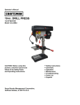
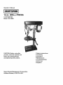
12-in. DRILL PRESS
1/2 HP MOTOR
Model 124.34985
CAUTION: Before using this
product, read this manual and
follow all its Safety Rules
and Operating Instructions.
® Safety Instructions
® Assembly
® Operation
• Maintenance
• Troubleshooting
® Parts List
• Espa_ol
Sears Brands Management Corporation,
Hoffman Estates, IL 60179 U.S.A
Warranty ..........................................................................................................................................................................................
Safety Instructions .....................................................................................................................................................................................
Specifications
......................................................................................................................................................
Glossary
of Terms ............................................................................................................................................
Safety ...........................................................................................................................................................................
Accessories
and Attachments
.....................................................................................................................................
Carton Contents ........................................................................................................................................
Assembly
...........................................................................................................................................
Adjustments
......................................................................................................................................
Operation
........................................................................................................................................
Maintenance
& Troubleshooting
..................................................................................................................................
Parts Diagram .................................................................................................................................................................................
Parts Lists ............................................................................................................................................
Repair Protection Agreement ......................................................................................................................................
Espafiol ..........................................................................................................................................................................................
FOR ONE YEAR from the date of purchase, this product is warranted against any defects in material or workmanship.
product will receive free repair or replacement if repair is unavailable.
For warranty coverage details to obtain free repair or replacement, visit the web site: www.craftsman.com
This warranty is void if this product is ever used while providing commercial services or if rented to another person.
This warranty gives you specific legal rights, and you may also have other rights which vary from state to state.
2
2-3
3
4
5
6
7
8-9
10-12
13-14
15
16
17-18
19
20
A defective
Sears Brands Management Corporation, Hoffman Estates, IL 60179
Proposition 65 Warning:
WARNING: Some dust created by power sanding, sawing, grinding, drilling, and other construction activities contains
chemicals known to the State d California to cause cancer and birth defects or other reproductive harm.
GENERAL SAFETY INSTRUCTIONS
BEFORE USING THE DRILL PRESS
1.
2.
3.
4.
5.
6.
7.
8.
9.
10. USE PROPER EXTENSION CORD. Make sure your
extension cord is in good condition. When using an extension
cord, be sure to use one heavy enough to carry the current
your product wilt draw. An undersized cord wilt result in a drop
in line voltage and in loss of power that will cause the tool to
overheat.
11. WEAR PROPER APPAREL. Do not wear loose clothing,
gloves, neckties, rings, bracelets, or other jewelry that may
get caught in moving parts. Nonstip footwear is
recommended. Wear protective hair covering to contain long
hair.
12. ALWAYS WEAR EYE PROTECTION. Any Drill Press can
throw foreign objects into the eyes that could cause
permanent eye damage. ALWAYS wear Safety Goggles
(not glasses). Everyday eyeglasses have only impactresistance lenses. They ARE NOT safety glasses.
13. SECURE WORK. Use clamps or a vise to hold work when
practical. It's safer than using your hand and it frees both
hands to operate toot.
14. DISCONNECT TOOLS before servicing; when changing
accessories such as blades, bits, cutters, and the like.
15. REDUCE THE RISK OF UNINTENTIONAL STARTING.
Make sure switch is in OFF position before plugging in.
16. USE RECOMMENDED ACCESSORIES. Consult the
Operator's Manual for recommended accessories. The use of
improper accessories may cause serious injury.
Safety is a combination of common sense, staying alert and
knowing how to use this Drill Press.
WARNING: To avoid mistakes that could cause serious injury,
do not plug the Drill Press in until you have read and
understood the following:
READ and become familiar with the entire Operator's Manual.
LEARN the tool's application, limitations and possible hazards.
KEEP GUARDS IN PLACE and in working order.
REMOVE ADJUSTING KEYS AND WRENCHES. Form a
habit of checking to see that keys and adjusting wrenches are
removed from the tool before turning ON.
KEEP WORK AREA CLEAN. Cluttered areas and benches
invite accidents.
DON'T USE IN DANGEROUS ENVIRONMENT. Don't use
power tools in damp or wet locations, or expose them to rain.
Keep work area welt lighted.
KEEP CHILDREN AWAY. All visitors should be kept at a safe
distance from work area.
MAKE WORKSHOP CHILDPROOF with padlocks.
DON'T FORCE THE TOOL. It will do the job better and safer
at the rate for which it was designed.
USE THE RIGHT TOOL. Do not force tool or attachment to do
a job for which it was not designed.
2
17. NEVER STAND ON TOOL. Serious injury could occur if the
tool is tipped or if the cutting tool is unintentionally contacted.
18. CHECK FOR DAMAGED PARTS. Before further use of the
tool, a guard or other part that is damaged should be carefully
checked to determine that it will operate properly and perform
its intended function - check for alignment of moving parts,
binding of moving parts, breakage of parts, mounting, and any
other conditions that may affect its operation. A guard or other
part that is damaged should be properly repaired or replaced.
19. NEVER LEAVE TOOL RUNNING UNATTENDED. TURN
POWER "OFF". Don't leave tool until it comes to a complete
stop.
20. DON'T OVERREACH. Keep proper footing and balance at all
times.
21. MAINTAIN TOOLS WITH CARE. Keep tools sharp and clean
for best and safest performance. Follow instructions for
lubricating and changing accessories.
22. DO NOT use power tools in the presence of flammable liquids
or gases.
23. DO NOT OPERATE the tool if you are under the influence of
any drugs, alcohol or medication that could affect your ability to
use the tool properly.
24. ALWAYS operate the Drill Press in a well-ventilated area and
provide for proper dust removal. Use dust collection systems
whenever possible. Dust generated from certain materials can
be hazardous to your health.
WARNING: For your own safety, do not try to use your drill press
or plug it in until it is completely assembled and installed
according to the instructions, and until you have read and
understood this instruction manual.
1. THIS DRILL PRESS is intended for use in dry conditions, indoor
use only.
2. WEAR EYE PROTECTION. USE a face or dust mask along
with safety goggles if drilling operation is dusty. USE ear
protectors, especially during extended periods of operation.
3. DO NOT wear gloves, neckties, or loose clothing.
4. DO NOT try to drill material too small to be securely held.
5. ALWAYS keep hands out of the path of a drill bit. Avoid
awkward hand positions where a sudden slip could cause your
hand to move into the drill bit.
6. DO NOT install or use any drill bit that exceeds 175mm
in length or extends 150mm below the chuck jaws. They can
suddenly bend outward or break.
7. DO NOT USE wire wheels, router bits, shaper cutters, circle (fly)
cutters, or rotary planers on this drill press.
8. WHEN cutting a large piece of material, make sure it is fully
supported at the table height.
9. DO NOT perform any operation freehand. ALWAYS hold the
workpiece firmly against the table so it will not rock or twist.
Use clamps or a vise for unstable workpieces.
10. MAKE SURE there are no nails or foreign objects in the part of
the workpiece to be drilled.
11. CLAMP THE WORKPIECE OR BRACE IT against the left
side of the column to prevent rotation. If it is too short or the
table is tilted, clamp it solidly to the table.
12. IF THE WORKPIECE overhangs the table such that it will fall
or tip if not held, clamp it to the table or provide auxiliary
support.
13. SECURE THE WORK. Use clamps or a vise to hold the work
when practical. It's safer than using your hand and it frees both
hands to operate tool.
14. MAKE SURE all clamps and locks are firmly tightened before
drilling.
15. SECURELY LOCK THE HEAD and table support to the
column, and the table to the table support before operating the
drill press.
16. NEVER turn your drill press ON before clearing the table of all
objects (tools, scraps of wood, etc.).
17. BEFORE STARTING the operation, jog the motor switch to
make sure the frill bit does not wobble or vibrate.
18. LET THE SPINDLE REACH FULL SPEED before starting to
drill. If your drill press makes an unfamiliar noise or if it vibrates
excessively, stop immediately, turn the drill press OFF and
unplug. Do not restart the unit until the problem is corrected.
19. DO NOT perform layout assembly or set up work on the table
while the drill press is in operation.
20. USE THE RECOMMENDED SPEED for any drill press
accessory and for different workpiece material.
21. WHEN DRILLING large diameter holes, clamp the workpiece
firmly to the table. Otherwise, the bit may grab and spin the
workpiece at high speeds. DO NOT USE fly cutters or multiple
part hold cutters, as they can come apart or become unbalanced in use.
22. MAKE SURE the spindle has come to a complete stop before
touching the workpiece.
23. TO AVOID INJURY from accidental starting, always turn the
switch OFF and unplug the drill press before installing or
removing any accessory or attachment or making any
adjustment.
Motor .............................................................
1/2 HP
Chuck ...............................................
0.63" / 16mm
Base Size ................. 16.54" x 9.84" / 420 X 250mm
Column ..............................................
2.28" / 58mm
Spindle
Spindle
Speed
Speeds
Swing ..............................................
1! .81" / 300mm
Total Height .....................................
35.43" / 900mm
Weight ........................................
80.47LBS / 36.5kg
Box Dimensions ................... 30.31"X17.72"X10.63"
Travel ...................................
2.44" / 62mm
Taper ....................................................
MT2
Changes ...................................................
12
............................................
355 / 3065 rpm
SAVE THESE INSTRUCTIONS.
Refer to them often.
3
BASE - Supports drill press. For additional stability, holes
are provided in base to bolt drill press to bench.
BACKUP MATERIAL - A piece of scrap wood placed
between the workpiece and table. The backup board
prevents wood in the workpiece from splintering when the
drill passes through the backside of the workpiece. It also
prevents drilling into the table top.
HEAD ASSEMBLY - Covers the pulleys and belt during
operation of the drill press.
BELT TENSION - Refer to the Assembly Section, "Installing and Tensioning Belt".
BELT TENSION LOCK KNOBS - Tightening the
knobs locks the motor bracket support and the belt tension handle, maintaining correct belt distance and tension.
BEVEL SCALE - Shows degree of table tilt for bevel
operations. The scale is mounted on the side of the table
bracket.
CHUCK - Holds a drill bit or other recommended accessory to perform desired operations.
CHUCK KEY - A self-ejecting chuck key which will pop
out of the chuck when you let go of it. This action is designed to help prevent throwing of the chuck key from the
chuck when the power is turned ON. Do not use any other
key as a substitute; order a new one if Damaged or Lost.
COLUMN - Connects the head, table, and base on a
one piece tube for easy alignment and movement.
COLUMN COLLAR - Holds the rack to the column. The
rack remains movable in the collar to permit table support
movements.
COLUMN SUPPORT - Supports the column, guides
the rack and provides mounting holes for the column to
the base.
DEPTH SCALE STOP NUTS - Lock the spindle to a
selected depth.
DEPTH SCALE - Indicates depth of hole being drilled.
DRILL BIT - The cutting tool used in the drill press to
make holes in a workpiece.
DRILL ON/OFF SWITCH - Has a locking feature. This
feature is intended to help prevent unauthorized and possible hazardous use by children and others. Insert the key
into the switch to turn the drill press on.
DRILLING SPEED - Changed by placing the belt in
any of the steps (grooves) in the pulleys. See the Spindle
Speed Chart inside belt guard or in the manual.
FEED HANDLE - Moves the chuck up or down. If
necessary, one or two of the handles may be removed
whenever the workpiece is of such unusual shape that it
interferes with the handles.
RACK - Combines with gear mechanism to provide easy
elevation of the table by the hand operated table crank.
RPM - Revolutions per minute. The number of turns completed by a spinning object in one minute.
SPINDLE SPEED - The RPM of the spindle.
SPRING CAP -Adjusts the spindle return spring tension.
TABLE BRACKET
LOCKING HANDLE -Tightening locks the table support tot he column. Always have it
locked in place while operating the drill press.
TABLE - Provides a working surface to support the workpiece.
TABLE ARM - Extends beyond the table support for
mounting and aligning the table.
TABLE TILT LOCK BOLT - Locks the table in any position from 0° to 45 °.
TABLE CRANK - Elevates and lowers the table. Turn
clockwise to elevate the table. Support lock must be released before operating the crank.
TABLE LOCK - Locks the table after it is rotated to various positions.
TABLE BRACKET - Rides on the column to support the
table arm and table.
WORKPIEOE
- Material being drilled.
ELECTRICAL
REQUIREMENTS
POWER SUPPLY AND MOTOR SPECiFiCATiONS
WARNING: To avoid electrical hazards, fire hazards, or damage to the
tool, use proper circuit protection. Use a separate electrical circuit for
your tools. To avoid shock or fire, if power cord is worn or cut, or damaged in any way, have it replaced immediately.
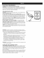
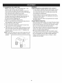
GROUNDING iNSTRUCTiONS
WARNING: This tool must be grounded while in use to protect the operator from electrical shock.
IN THE EVENT OF A MALFUNCTION OR BREAKDOWN, grounding
provides a path of least resistance for electric current and reduces the
risk of electric shock. This tool is equipped with an electric power cord
that contains an equipment-grounding conductor wire and a 3-prong
plug with a grounding pin. The plug MUST be plugged into a matching
receptacle that is properly installed and grounded in accordance with
ALL local codes and ordinances.
DO NOT MODIFY THE PLUG PROVIDED. If it will not fit the receptacle, have the proper receptacle installed by a qualified electrician.
IMPROPER CONNECTION of the power cord can result in risk of electric shock. If repair or replacement of the electric cord or plug is necessary, DO NOT plug it into an electrical outlet.
CHECK with a qualified electrician or service person if you do not completely understand the grounding instructions, or if you are not sure the
tool is properly grounded.
WARNING: Improper connection of equipment grounding conductor
can result in the risk of electrical shock. Equipment should be grounded
while in use to protect operator from electrical shock.
- Check with a qualified electrician if you do not understand grounding
instructions or if you are in doubt as to whether the tool is properly
grounded.
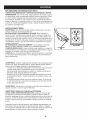
- This tool is equipped with an approved cord and a 3-prong grounding
type plug for your protection against shock hazards.
- Grounding plug should be plugged directly into a properly installed
and grounded 3-prong grounding-type receptacle, as shown.
- Do not remove or alter grounding pin in any manner. In the event
of a malfunction or breakdown, grounding provides a path of least
resistance for electrical shock.
WARNING: This Drill Press is for indoor use only. Do not expose to rain
or use in damp locations.
GUIDELINES
FOR EXTENSION
CORDS
USE PROPER EXTENSION CORD. Make sure your extension cord is
in good condition. When using an extension cord, be sure to use one
heavy enough to carry the current your product will draw. An undersized
cord will cause a drop in line voltage, resulting in loss of power and
cause overheating.
Be sure your extension cord is properly wired and in good condition. Always replace a damaged extension cord or have it repaired by a qualified person before using it. Protect your extension cords from sharp
objects, excessive heat and damp or wet areas.
h
COVER OF GRINDED
OUTLET BOX
!
:
i
CARTON
CONTENTS
UNPACKING
AND CHECKING
CONTENTS
Carefully unpack the Drill Press and all its parts, and compare against the
illustration following.
WARNING:
• To avoid injury from unexpected starting, do not plug the power cord into a
power source receptacle during unpacking and assembly. This cord must
remain unplugged whenever you are assembling or adjusting the drill press.
• If any part is missing or damaged, do not plug the drill press in until the missing or damaged part is replaced, and assembly is complete.
• To protect the drill press from moisture, a protective coating has been applied
to the machined surfaces.
Remove this coating with a soft cloth moistened with kerosene.
WARNING: To avoid fire or toxic reaction, never use gasoline, naphtha, acetone,
lacquer thinner or similar highly volatile solvents to clean the drill press.
TABLE OF LOOSE PARTS
Unpack carton: check the machine to see parts listed below:
A.
Main parts
See Fig. 1
1. Head assembly
2. Column Assembly
3. Table
4. Base
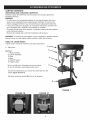
5. ON/OFF Switch
6. Flexible Lamp
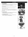
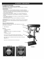
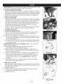
To turn on drill press, lift paddle switch from bottom.
To turn off drill press, push paddle switch down.
To prevent unauthorized use, remove the center key from the
switch. Figure IB and 1C
Drill press cannot be turned ON if key is not inserted.
FIGURE
FIGURE
1B
FIGURE
1C
1
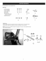
B. Accessories
(in one separate box)
See Fig.2
B. Crank handle
C. Hex wrenches
D. Feed
Hex bolts
A.
handles
E. Chuck key
F. 5/8=inch Chuck and
chuck removal tool
G Table fence set
I
I
I
_/_
C
A
D
B
E
F
Table Fence
Use the supplied hardware to attach the fence to the table as shown in the picture below.
Use the fence to align the workpiece and provide a backstop for secure drilling.
NOTE: Table pictured is different shape than equipped with product. Fence attaches through
slots in the same manner.
Q
Wingnuts
G
1. Column support to base
1.1 Position the base on floor or bench.
1.2 Place the column on the base, aligning the holes in the column
support with the holes in the base.
1.3 Locate the four long hex bolts from the loose parts bag.
1.4 Place a bolt in each hole through the column support and the
base. Tighten with an adjustable wrench. See Fig. I
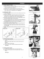
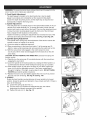
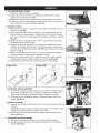
2. Installing
the Table
2.1 Loosen set screw (1). Remove rack (2) and retaining ring (3) from
column (4). Fig. 2A
2.2 Place rack inside table assembly bracket (5) with large, unmachined portion of rack to the top. Slide rack into slot in bracket so
that teeth of rack engage pinion gear in bracket. Fig. 2A
2.3 Slide table assembly with rack over column. Place bottom end of
rack inside beveled edge of column flange.
2.4 Slide rack retaining ring (3) over column with beveled edge down.
Position ring against top of rack so that rack is in beveled edge of
ring. Fig. 2B Secure ring with set screw (1). Fig. 2C
2.5 Rotate table assembly around column. Adjust rack retaining ring
as necessary to prevent binding of rack.
2.6 Attach crank handle (6) to shaft (7), rotate to remove slack, and
shoulder crank handle against table bracket. Secure handle with
screw. Fig. 2B
2.7 Tighten table bracket locking handle (9) to secure table assembly.
Fig. 3
Figure
2A
Figure
Figure
1
Figure
20
Figure
3
Figure
4
Figure
5
2B
4
,p
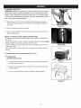
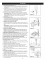
3. Installing head assembly
3.1. Carefully lift the head above the column and slide it onto the
column.
Make sure the head slides down over the column as far as
possible.
Align the head with the base.
3.2. Using the hex wrench, tighten the head lock set screws.
See Fig. 4
4. Installing feed handles
4.1. Locate the three feed handles in the loose parts box.
4.2. Screw the feed handles into the threaded holes in the hub.
Tighten.
See Fig. 5.
8
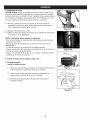
5. Installing the chuck
WARNING:
Before any assembly of the chuck and arbor to the drill
press head, clean all mating surfaces with a non-petroleum
based
product; such as alcohol or lacquer thinner. Any oil or grease used
in the packing of these parts must be removed;
may come loose during operation.
otherwise
the chuck
5.1 Open the jaws of the chuck by rotating the chuck sleeve clockwise.
To prevent damage, make sure the jaws are completely receded into
the chuck.
Figure
6
Figure
6A
Figure
7
Figure
8
5.2 Push the chuck shaft into the spindle.
5.3.Use a wooden mallet to firmly tap the chuck securely into place in the
spindle. See Fig. 6.
NOTE: To remove chuck perform the following:
- Rotate the chuck sleeve clockwise until the jaws recede completely into
the chuck.
- Lower the spindle as far as it will go to reveal the spindle slot, See Fig.6A
- Raise the table to a position just below the the chuck.
- Insert the tip of the chuck removal tool into the spindle slot above the tip
of the chuck shaft.
- Tap on the blunt end of the wedge tool until the chuck releases from the
spindle,
6. install
knob
for the head assembly
7. Flexible lamp
Install the flexible
I
lid. Fig. 7
lamp
7.1. Connect the lamp plug contact to the power source plug contact in
the drill head as shown,
7.2. Use four pan head screws to install the lamp assembly to the drill
head as shown,
7.3. Turn on the flexible lamp switch to check the lighting. Fig. 8
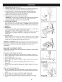
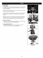
1. Table adjustment
A. Tilting adjustment
- On underside of table support bracket, back out set screw with supplied
hex wrench, Loosen large hex head bolt, See Fig, 9
- Rotate table to desired angle right or left. Use bevel scale for precise
setting, See Fig, 10
- Tighten hex head bolt to secure table tilt. Set screw should not be
tightened when table is tilted,
Figure
9
Figure
10
Figure
11
Figure
12
- To return table to level, loosen large hex head bolt. Rotate table to level
position. Use hex wrench to retighten set screw, Securely tighten large
hex head bolt,
B. Height adjustment
Loosen the clamp bolt then adjust the table to your desired position by
turning the table bracket crank handle. See Fig. 11
C. Swing Adjustment
360 °
Loosen the table swing locking handle, then swing table to desired
position and retighten the handle, See Fig. 12
Crank
handle
10
WARNING: To prevent personal injury, always disconnect the plug from the
power source when making any adjustment.
2. Feed Depth Adjustment
The depth gauge is located on the feed handle hub. Use the depth
gauge to accurately and consistently set the required drilling depth.
Loosen the depth stop fixing screw, set the depth stop as required and
subsequently re-tighten the fixing screw.
3. Speed Adjustment
This drill press has 12 speeds shown in the speed label located on the underside of the head assembly lid. To change the speed, loosen the belt
tension lock knob on each side of the head. Then use the adjustment lever
to draw the motor mounting plate toward the front end of the drill head.
Next, change the belt locations on the pulleys.
Tighten the belts by pushing the adjustment lever towards the rear of the
drill head and locking the belt tension knobs. See Fig.13 and Fig.13A
4. Spindle Spring Adjustment
The spindle return spring may need adjustment if the tension causes the
spindle to return too rapidly or too slowly.
4.1 Lower the table for additional clearance.
4.2 Place a screwdriver in the lower front notch (1) of the spring cap (2).
Hold it in place while loosening and removing only the outer lock nut (3).
4.3 With the screwdriver still engaged in the notch loosen the inner
nut (4) just until the notch (5) disengages from the boss (6) on the drill
press head.
CAUTION: DO NOT REMOVE THIS INNER NUT, because the spring will
forcibly unwind.
4.4 Carefully turn the spring cap (2) counterclockwise with the screwdriver,
engaging the next notch.
4.5 Lower the spindle to the lowest position by rotating the feed handle in a
counterclockwise direction while holding the spring cap (2) in position.
4.6 If the spindle moves up and down as easily as you desire, tighten the
inner nut (4) with the adjustable wrench. If too loose, repeat steps 2
through 4 to tighten. If too tight, reverse steps 3 and 4. DO NOT OVERTIGHTEN and restrict spindle movement.
4.7 Replace the lock nut (3) and tighten against the inner nut (4) to prevent
the inner nut from reversing. See Fig.14 and Fig. 14A
5. SPINDLE
Rotate the feed handles counterclockwise to lower spindle to its lowest
position. Grasp the spindle and attempt to move it back and forth. If there is
play, do the following:
5.1 Loosen the spring cap lock nut (1).
5.2 Turn the screw (2) clockwise to eliminate the play, but without
obstructing the upward movement of the spindle.
5.3 Tighten the lock nut (1). See Fig. 15
11
Figure
12
Figure
13
Figure
13A
6
1
Figure
14
Figure
14A
Figure
15
6. ADJUSTING
THE LASER LINE
NOTE: Laser pointer (1) is an alternative part. Your
machine may not have this laser pointer.
How to check and adjust the Laser Beam Alignment:
Check the laser beam alignment to ensure the intersection of the laser lines precisely at the spot
where the drill bit meets the workpiece. If it is not,
the laser lines should be adjusted using the laser adjustment knobs located on the opposite sides of
the head assembly. See Fig. 16
1. Mark an "X" on a piece of scrap wood.
2. Insert a small drill bit into the chuck and align its tip to
the intersection of the lines of the "X".
3. Secure the board to the table.
4. Turn on the laser switch(3) and verify the laser lines
align with the "X" on the workpiece.
5. If the laser lines do not align, loosen knobs(2) on each
side of the laser module and rotate the lasers(4) until
the lines meet in the center of the "X". Retighten the
knobs to secure.
NOTE: Check and adjust the laser beam alignment every
time the drill _ress table is raised or lowered to a new
position.
WARNING!
LASER RADIATION: AVOID DIRECT EYE CONTACT
• A Laser light is radiated when the laser guide is turned
on. Avoid direct eye contact. Always turn off the laser
and unplug the drill press from the power source before making any adjustments.
• A laser pointer is not a toy and should not come into
hands of children. Misuse of this appliance can lead to
irreparable eye injuries.
• DO NOT attempt to make any adjustments to increase
the laser power.
ADJUSTMENT/OPERATION
• When using the laser pointer, do not point the laser beam
towards people and / or reflecting surfaces. Even a laser
beam of lower intensity may cause eye damage. There
fore, do not look directly into the laser beam.
• If the laser pointer is stored for more than three months
without use, please remove the batteries to avoid damage from possibly leaking batteries.
• The laser pointer includes no user serviceable components. Never open the housing for repair or adjustments.
• On units equipped with the Laser-Guide attachment,
repairs must be performed only by a Sears or other
qualified service dealer.
CD
12
1. Installing A Drill Bit See Fig. 16
1.1. With the switch "OFF", open the chuck jaws (1) using the chuck key (2).
Turn the chuck key counterclockwise to open the chuck jaws (1).
1.2. Insert the drill bit (3) into the chuck far enough to obtain maximum
gripping by the jaws, but not far enough to touch the spiral grooves
(flutes) of the drill bit when the jaws are tightened.
1.3. Make sure that the drill is centered in the chuck.
1.4. Turn the chuck key clockwise to tighten the jaws.
WARNING: To avoid injury or accident by the chuck key ejecting forcibly
from the chuck when the power is turned ON, always recheck and
remove the chuck key before turning the power ON.
Figure
16
Figure
17
Figure
18
Figure
19
Figure
20
2. Positioning
Workpiece
If not using table fence, to prevent the workpiece or back-up material from
being torn from your hands while drilling, you MUST position it against the
LEFT side of the column. Failure to do this could result in personal injury.
See Fig.17
3. Using Vise
For small workpiece that cannot be clamped to the table, use a drill press
vise. The vise must be clamped or bolted to the table.
WARNING: The drill press vise MUST be clamped or bolted to the table to
avoid injury from a spinning workpiece, or damaged vise or bit parts.
See Fig.18
4. Drilling
a Hole
Using a center punch or a sharp nail, make an indentation in the workpiece
where you want to drill. Turn the power switch on and pull down the feed
handles with only enough effort to allow the drill to cut.
FEEDING TOO RAPIDLY might cause the belt or drill to slip, tear the workpiece loose, or break the drill bit. When drilling metal, it will be necessary to
lubricate the tip of the drill bit with metal drilling oil to prevent it from
overheating.
DRILLING
TO A SPECIFIC
DEPTH
Drilling a blind hole (not all the way through the workpiece) to a given depth
can be done two ways:
Workpiece method (Figure 19 and 20)
1. Mark the depth (1) of the hole on the side of the workpiece. (Figure 16).
2. With the switch "OFF", bring the drill bit (2) down until the tip is even with
the mark (Figure 19).
3. Hold the feed handle at this position.
4. Spin the lower nut (3) down to contact the depth stop lug (6) on the head
(Figure 20).
5. Spin the upper nut (5) down and tighten against the lower nut (3)
(Figure 20).
6. The drill bit will now stop after traveling the distance marked on the workpiece.
Depth scale method (Figure 20)
1. With the switch "OFF", turn the feed handle until the pointer (7) points to
the desired depth on the depth scale (4) and hold the feed handle in that
position.
2. Spin the lower nut (3) down to contact the depth stop lug (6).
3. Spin the upper nut (5) against the lower stop nut and tighten.
4. The drill bit will stop after traveling the distance selected on the depth
scale.
13
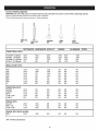
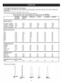
Correct
Drilling
Speeds
WARNING: Be sure drill press is turned off and is disconnected
Use the recommended speed for the drill bit and workpiece.
The drill bits that can be used are shown in following figure:
from power sours before adjusting
speeds.
DRILL
_POINT
_'1'8
TWIST
FOR_ER
SPADE
SOFTWOOD
HARDWOOD
ACRYLIC
BRASS
ALUMINUM
3000
3000
1500
750
3000
1500
750
500
2500
2000
1500
NR
3000
1200
750
400
3000
2500
1500
1000
3000
1000
800
250
1800
1800
1800
1800
1800
1400
1200
1000
1200
1000
750
750
500
250
250
250
1500
1500
1500
1000
750
750
500
200
NR
NR
NR
NR
NR
NR
NR
NR
NR
NR
NR
NR
NR
NR
NR
NR
NR
NR
NR
NR
NR
NR
NR
NR
2400
2400
1500
1000
500
700
500
500
250
250
250
250
250
250
NR
NR
NR
NR
NR
NR
NR
NR
NR
NR
NR
NR
NR
NR
NR
NR
2000
1750
1500
1500
1500
1000
NR
NR
NR
NR
NR
NR
NR
NR
NR
NR
NR
NR
1800
500
NR
NR
NR
DRILL BiTS
1/16-3/16" (3-Smm)
114-318" (6-10mm)
7/16-5/8" (11-16mm)
11/16-1" (11-25mm)
BRAD-POINT
BiTS
1/8"
1/4"
3/8"
112"
5/8 "
3/4"
7/8"
1"
FORSTNER
1/4-3/8"
1/2-5/8"
3/4-1"
1-1/8-1 1/4"
1=3/8=2"
BITS
SPADE BITS
1/4-1/2"
5/8-1-1/2"
1-118-1-112"
SPADE BITS WITH SPURS
3/8=1"
2000
NR - Not Recommended
14
STEEL
MAiNTAiNiNG
YOUR
DRILL
PRESS
LUBRICATION
All of the drill press ball bearings are packed with grease
at the factory, They require no further lubrication, Lower
spindle to maximum depth and oil moderately once every
three months.
WARNING: For your own safety, turn the switch OFF and
remove the plug from the power source outlet before maintaining or lubricating your drill press.
Frequently blow out any dust that accumulates inside the
motor with an air compressor or dust vacuum. A coat of
paste wax applied to the table and column will help to keep
the surface clean & help avoid rust.
To avoid shock or fire hazard, if the power cord is
worn or cut on any way, have it replaced immediately.
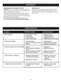
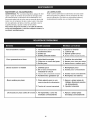
Noisy Operation
Bit Burns
or Smokes
1. Incorrect
Belt Tension
2. Dry spindle
1. Adjust Tension
2. Lubricate
spindle
3. Loose
4. Loose
3. Tighten
4. Tighten
pulley nut
set screw in pulley
1. Change
speed
spindle
motor pulley
1. Incorrect
speed
2. Chips not coming
3. Dull bit
Excessive
drill bit
run out or wobble
1. Bent bit
in workpiece
torn loose
from
hand
installed
in
2. Install
bit
bit properly
3. Chuck not properly installed
4. Worn spindle bearings
3. Install chuck properly
4. Replace bearings
1. Workpiece
excessive
1. Support or clamp work
piece, decrease feed
pressure
2. Adjust tension
2. Improper
Workpiece
2. Retract bit to clear chips
3. Sharpen or replace bit
1. Replace
2. Bit not properly
chuck
Drill bit binds
out of hole
pinching bit or
feed pressure
belt tension
1. No supported
properly
15
or clamped
1. Support or clamp
piece properly
work
Cb
67_--
88- 10__
'\,7 2
16
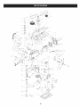
KEY NO.
MFG. PART NO.
QUANTITY
1
2
3
4
5
6
7
8
9
10
11
12
13
14
15
16
17
18
19
20
21
22
23
24
24-1
24-2
24-3
24-4
24-5
24-6
24-7
25
26
27
28
29
30
31
32
33
34
35
36
37
38
39
40
41-1
41-2
41-3
41-4
41-5
41-6
41-7
41-8
41-9
41-10
41-11
41-12
41-13
42
43
44
45
46
47
48
49
Retaininq ring
Strain relief
Retaining ring
_ear!ng
_eanng
Retaining rin.q
Nameplate la-ble
Spindle pulley
Bolt
O-belt
Bearing
O-belt
Small belt pulley
Bolt
Middle pulley
Shaft
Knob
Flat washer
Toothed washer
Bolt
Bolt
Flat washer
Speed lable
Pulley assembly
Bolt
Flat washer
Line clamp
Flat washer
Nut
Coil
Coil
Rubber washer
Flat washer
Spring washer
Nut
Flat washer
Nut
Motor
Connection board
Shaft
Bolt
Sliding shaft
Bolt
Tool
Toolpin
Headstock
Bolt
Laser assembly
Ferrule
Bolt
LED light
Bolt
LED liqht seat
Transformer
Bolt
Transformer seat
Bolt
Bolt
Flat washer
Seat
Bolt
Retaining ring
Handle
Nut
Disc spring seat
Spring
Nut
Bolt
1
1
1
1
1
1
1
1
2
1
2
1
1
1
1
1
1
1
1
1
4
4
1
1
3
3
3
3
3
2
1
4
4
2
2
8
4
1
1
1
4
1
1
1
1
1
2
1
1
2
1
4
1
1
2
1
2
1
1
1
2
1
1
2
1
1
1
1
17
KEY NO.
50
51
52
53
54
54-1
54-2
55
56
57
58
59
60
61
62
63
64
65
66
67
68
69
70
71
72
73
74
75
76
77
78
79
80
81
82
83
84
85
86
87
88-1
88-2
88-3
88-4
88-5
88-6
88-7
88-8
88-9
88-10
89
90
91
92
93
94
95
96
97
98
99
100
101
102
103
104
105
106
MFG. PART NO.
QUANTITY
Toothed washer
Flat washer
Bolt
Switch box
Switch
Plate
Small switch
Bolt
Bolt
Warning lable
Pointer
Rivet
Bolt
Reduction vibration ring
Retaining ring
Bearinq
Track sleeve
Bearing
Wedcle
Spindle
Cone shaft
Chuck
Base
Flange
Bolt
Spring washer
Bolt
Column
Track
Handle assembly
Bolt
Retaining ring
Small gear
Pin shaft
Lockinq handle assembly
Bracket
Pointer
Rivet
An qle lable
TalSle
Bolt
Flat washer
Knob
Parallel fence
Vertical fence
Flat washer
Knob
Bolt
Pin
Nut
Locking handle assembly
worm
Collar
Bolt
Clamp ring
Handle cover
Handle
Handle plate
Gear shaft
Pin
Dial
Rivet
Depth lable
Bolt
Line cord
Insulation sleeve
Terminal
Terminal
1
1
1
1
1
1
1
2
2
1
1
1
1
1
1
1
1
1
1
1
1
1
1
1
1
1
4
1
1
1
1
1
1
1
1
1
1
2
1
1
1
4
2
1
1
1
1
2
1
1
1
1
1
1
1
3
3
1
1
1
1
1
1
1
1
4
2
4
18
Repair Protection Agreements
Congratulations on making a smart purchase. Your new
Craftsman® product is designed and manufactured for years of
dependable operation. But like all products, it may require repair
from time to time. That's when having a Repair Protection
Agreement can save you money and aggravation.
Here's what the Repair Protection Agreement*
includes:
[] Expert service by our 10,000 professional repair specialists
[] Unlimited service and no charge for parts and labor on all
covered repairs
[] Product replacement up to $1500 if your covered product
can't be fixed
[] Discount of 25% from regular price of service and related
installed parts not covered by the agreement; also, 25% off
regular price of preventive maintenance check
[] Fast help by phone - we call it Rapid Resolution phone support from a Sears representative. Think of us
as a "talking owner's manual."
Once you purchase the Repair Protection Agreement, a
simple phone call is all that it takes for you to schedule service.
You can call anytime day or night, or schedule a service
appointment online.
The Repair Protection Agreement is a risk-free purchase. If
you cancel for any reason during the product warranty period,
we will provide a full refund. Or, a prorated refund anytime after
the product warranty period expires. Purchase your Repair
Protection Agreement today!
Some limitations and exclusions apply. For prices and
additional information in the U.S.A. call 1-800-827-6655.
*Coverage in Canada varies on some items. For full details
call Sears Canada at 1-800-361-6665.
Sears Installation
Service
For Sears professional installation of home appliances, garage
door openers, water heaters, and other major home items, in the
U.S.A. or Canada call 1-800-4=MY-HOME®.
f9
Garantia .............................................................................................................................................................................
Las instrucciones
de seguridad ...................................................................................................................................
Especificaci6ns
.....................................................................................................................................
Seguridad ..................................................................................................................................................................................
Accesorios
y Complementos
...................................................................................................................................
Glosario
de Terminos .......................................................................................................................................
Et cart6n Contenido
......................................................................................................................................
Asambtea
.........................................................................................................................................
Ajuste .........................................................................................................................................
Operaci6n
........................................................................................................................................
Soluci6n de problemas ...................................................................................................................................................................
Reparar Acuerdo de Protecci6n ..................................................................................................................................................................
20
20-21
21
22
23
24
25
26-27
28-29
30-31
32
33
Durante un afio a partir de la fecha de compra, este producto esta garantizado contra defectos en los materiales o la mano. Un
producto defectuoso se reciben reparaci6n gratuita o reemplazo si la reparaci6n no este disponible.
Para la cobertura de garant[a los detalles para conseguir reparaci6n gratuita o reemplazo, visite el sitio web: www.craftsman.com
Esta garant[a le da derechos legales especificos, y tambien podria tener otros derechos que varian de estado a estado.
Sears Brands Management
La Proposicion
Corporation,
Hoffman Estates, IL 60179
65 Advertencia:
Advertencia: Atgunos polvo creado al tijar, serrado, rectificado, taladrado, y otras actividades de construcci6n contiene
sustancias quimicas que se sabe que et Estado de California, que causa cancer y defectos de nacimiento u otros dafios
reproductivos.
INSTRUCCIONES
DE SEGURIDAD
GENERALES
ANTES
DE UTILIZAR LA TALADRADORA
1.
2.
3.
4.
5.
6.
7.
8.
9.
La seguridad es una combinaci6n de sentido comQn,
mantenerse alerta y saber c6mo utilizar esta Taladradora.
ADVERTENCIA: Para evitar errores que podrian causar un
dafio grave, no 1oconecte ta Taladradora en hasta que usted
ha leido y entendido los siguientes:
Lea y famitiaricese con el Manual del Operador. CONOCER la
herramienta de aplicaci6n, timitaciones y posibles peligros.
MANTENER LOS guardias en su lugar y funcionando.
QUlTAR ajustar tas llaves y llaves. Formar un habito de
comprobar que tas ctaves y el ajuste llaves se quitan de la
herramienta antes de encender.
Mantenga limpia el area de trabajo. Amontonado ambitos y
bancos invitamos a accidentes.
NO UTILICE en ambientes peligrosos. No utilice herramientas
electricas en lugares hOmedos o mojados, o exponertos a la
lluvia. Mantenga el area de trabajo bien ituminada.
Mantener alejados A LOS NII_IOS. Todos los visitantes deben
mantenerse a una distancia segura de area de trabajo.
HAGA EL TALLER CERRADURAS con candados.
No fuerce ta herramienta. Lo hara el trabajo mejor y mas
seguro a la tasa para el que fue concebido.
UTILICE LA HERRAMIENTA derecha. No fuerce herramienta
o apego a realizar trabajos para los que no fue disefiado.
10. USO CORRECTO cable de extensi6n. Asegt_rese de que
el cable de extensi6n se encuentra en buen estado. Cuando
se utiliza un cable de extensi6n, asegOrese de usar un calibre
suficiente para conducir ta corriente su producto. Un cable
de tamafio menor se traducira en una caida de tensi6n
en la linea yen una perdida de energia que causara la
herramienta a recalentarse.
11. USAR vestimenta adecuada. No use ropa suelta, guantes,
corbatas, anittos, pulseras, u otro tipo de joyas que pueden
quedar atrapados en las piezas m6vites. No se recomienda
usar calzado antideslizante. Use una cubierta protectora para
contener el cabelto largo.
12. Siempre use protecci6n para los ojos. La Taladradora puede
arrojar objetos extrafios en los ojos que puede causar dafio
permanente a los ojos. Siempre utitice gafas de seguridad
(no tentes). Gafas de uso diario s61o impacto- lentes
resistencia. NO SON lentes de seguridad.
13. TRABAJO SEGURO. Usar abrazaderas o una prensa de
tornilto para celebrar cuando trabajo practico. Es mas
seguro que usar su mano y libera ambas manos para operar
herramienta.
14. DESCONECTE herramientas antes del servicio; cuando
se cambian los accesorios tales como las cuchillas, brocas,
cortadores, y similares.
15. REDUCIR EL RIESGO DE PARTIDA no intencionales.
AsegOrese de interruptor se encuentra en posici6n de
apagado antes de conectar.
16. USO RECOMENDADO ACCESORIOS. Consulte el
manual del operador para accesorios recomendados. El
uso de accesorios inapropiados puede causar lesiones
graves.
20
17. Nunca se pare SOBRE LA HERRAMIENTA. Lesiones graves
pueden ocurrir si la herramienta se inclina o si la herramienta
de corte involuntariamente contactados.
18. DISPONER DE PARTES daSadas. Antes de seguir usando
la herramienta, un guardia o en alguna otra parte que esta
daSado deben verificarse cuidadosamente para determinar
que funcionara correctamente y realizar su funci6n prevista revise la alineaci6n de los elementos m6vites, obtigatorio de
piezas m6vites, rotura de las partes, det montaje, asi como cualesquiera otras condiciones que puedan afectar a su funcionamiento. Un guardia o en alguna otra parte que esta daSada
debe ser correctamente reparado o sustituido.
19. NUNCA deje DESATENDIDA HERRAMIENTA mientras este
funcionando. Apague la unidad "OFF". No dejes herramienta
hasta que se detenga por completo.
20. NO EXCEDERSE. Mantener una verdadera igualdad y
equitibrio en todo momento.
21. MANTENIMIENTO DE LAS HERRAMIENTAS CON
CUIDADO. Mantenga las herramientas brusco y limpios para
rendimiento mejor y mas segura. Siga tas instrucciones para
lubricar y cambiar los accesorios.
22. NO utitice herramientas etectricas en presencia de liquidos o
gases inflamables.
23. NO UTILICE ta herramienta si usted esta bajo ta influencia de
cualquier tipo de drogas, alcohol o medicamentos que podrian
afectar a su capacidad de utitizar ta herramienta correctamente
24. Siempre opere la Taladradora en un area bien ventitada y
prever la adecuada etiminaci6n de polvo. Utitizar sistemas de
recogida potvo siempre que sea posibte. El polvo generado de
determinados materiales pueden ser petigrosos para su salud.
ADVERTENClA:
Por su
perforadora
o conectelo
instalado de acuerdo con
entendido este manual de
12. Sl LA PIEZA sobresale por encima de la mesa, que va a
caer o sugerencia si no se mantienen abrazadera de la tabla o
proporcionar apoyos auxiliares.
13. GARANTIZAR EL TRABAJO. Usar abrazaderas o un sargento que
mantenga el trabajo cuando sea practico. Es mas seguro que usar su
mano y libera ambas manos para operar herramienta.
14. Asegerese de que todos abrazaderas y cerraduras estan bien
apretados antes de perforar.
15. PONER CANDADO LA CABEZA yen el cuadro apoyo a la columna, y
la tabla al soporte de tabla antes de operar la taladradora.
16. Nunca apague su prensa perforadora antes de limpiar la mesa de
todos los objetos (herramientas, pedazos de madera, etc.)
17. Antes de iniciar la operaci6n, jog el motor switch para asegurarse de
que el ramillete poco no tiemble o vibre.
18. QUE EL HUSO alcanzan su velocidad antes de comenzar a
propia seguridad,
no intente usar su prensa
hasta que quede completamente
montado e
las instrucciones, y hasta que no haya leido y
instrucciones.
1. Esta PRENSA PERFORADORA esta dise_ada para su uso en
condiciones secas, s61o para uso en interiores.
2. USE PROTECClON PARA LOS OJOS, Utilice una cara o
mascarilla junto con gafas de seguridad si la perforaci6n
esta Ileno de polvo. USAR protectores auditivos, especialmente
durante periodos prolongados de operaci6n.
3. NO use guantes, corbatas, o ropa holgada.
4. NO SE DEBE intentar perforar material demasiado pequeSo
para ser sujetado firmemente.
5. Siempre mantenga las manos fuera del camino de una broca.
Evitar posiciones inc6modas mano donde un deslizamiento
repentino podria causar que su mano para irse a la broca.
6. NO instale o la utilizaci6n de una broca que supera 175mm
de Iongitud o se extiende 150mm mas abajo el portabrocas las
mandibulas. De repente pueden doblarse hacia afuera o romper.
7. NO UTILIZAR ruedas de alambre, moldeador enrutador bits,
cortadores, circle (mosca) cortadores, o los cepillos giratorios
en la taladradora.
19.
20.
21.
8. AI cortar un pedazo grande de material, asegQrese de que
cuenta con el pleno apoyo a la altura de la mesa.
9. No realice ninguna operaci6n freehand. Siempre mantenga
la pieza de trabajo firmemente contra la mesa de forma que no
rock o twist. Usar abrazaderas o un sargento de inestable
piezas mecanizadas.
10. AsegQrese de que no hay clavos u objetos extraSos en la
parte de la pieza que va a taladrar.
11. Sujete la pieza o CORS¢:, en contra de la parte izquierda de
la columna para impedir que la lente. Si es demasiado corto o
inclinaci6n de la mesa, abrazadera firmemente a la tabla.
22.
23.
perforar. Si la taladradora hace un extraSo ruido, o siesta vibra,
detener inmediatamente, gire la taladradora y desenchufe. No reinicie
la unidad hasta que el problema se corrige.
NO realice diseSo asamblea o un conjunto de trabajos sobre la mesa,
mientras la prensa perforadora esta en funcionamiento.
UTILIZAR LA VELOClDAD recomendada para cualquier accesorio
taladradora y piezas de diferentes materiales.
AI taladrar agujeros grandes diametros, sujete la pieza de trabajo
firmemente a la tabla. De Io contrario, el bit grab y girar la pieza a altas
velocidades. NO UTILICE volar cortadores o mQItiples parte mantenga
cortadores, como pueden venir aparte o ser equilibrado en uso.
Asegerese de que el eje ha Ilegado a su fin por completo antes de
tocar la pieza de trabajo.
Para evitar daSos en caso de arranque accidental, siempre apagar el
interruptor y desconecte la taladradora antes de instalar o quitar
cualquier accesorio o archivos adjuntos, o hacer cualquier ajuste.
Motor .............................................................
1/2 HP
Lanzar ..................................................
0.63"-16mm
TamaSo Base ............. 16.54" x 9.84"-420 X 250mm
Columna ..............................................
2.28"-58mm
Eje de Viaje .........................................
2.44"- 62mm
Eje Afiautan ......................................................
MT2
Cambio de Velocidad ...........................................
12
Velocidad .......................................
355 / 3065 r/min
Columpio .........................................
AItura total .......................................
GUARDAR
Referirse
Cargar .........................................
80.47LBS- 36.5kg
Dimensiones
de la Caja.30.31"X17.72"X10.63"770X450X270mm
estas instrucciones.
a ellos
con frecuencia.
21
11.81"- 300mm
35.43"- 900mm
NECESIDADES
FUENTE
DE ENERGiA
DE ALIMENTACI6N
ELECTRICA
Y ESPECIFICACIONES
DEL MOTOR
ADVERTENCIA:
Con et fin de evitar riesgos etectricos, de incendio, o dafios
a la herramienta, utilice una adecuada protecci6n contra cortocircuitos. Utitizar
un circuito etectrico separado para sus herramientas. La taladradora esta
inmovitizada en la fabrica de 115V. Conectar a 115V, circuito de 15 amperes y
utitizar un retardo de 15 amperes fusibtes ou. Con et fin de evitar descarga o un
incendio, si el cable esta desgastado o cortar, o dafiado de alguna manera, se
han sustituido inmediatamente.
INSTRUCCIONES
TIERRA
ADVERTENCIA: Esta herramienta debe basarse mientras esta en uso para
proteger al operador de descargas etectricas.
EN CASO DE MAL FUNClONAMIENTO O AVERiA, tierra constituye un
camino de menor resistencia para corriente etectrica y reduce et riesgo de un
choque etectrico. Esta herramienta esta equipado con un cable electrico que
contiene un equipo de hito conductor a tierra y un enchufe de tres patas con un
receptaculo pin. Et enchufe debe estar conectado a un tomacorriente que esta
correctamente instalado y que se fundamenten en conformidad con todos los
c6digos y ordenanzas.
NO MODIFIQUE EL CONECTOR SIEMPRE. Si no se adapte al recipiente,
tienen et recipiente adecuado instalado por un etectricista calificado.
CONEXlON INADECUADA El equipo de tierra puede resultar en un riesgo de
descarga etectrica. Si ta reparaci6n o et reemplazo det cable etectrico o plug es
necesaria, no conecteto a una toma de corriente etectrica.
CONSULTE con un electricista cualificado o persona de servicio si no entiende
por completo ta tierra instrucciones, o si no esta seguro de la herramienta es
tierra correctamente.
ADVERTENClA:
Conexi6n inadecuada det conductor a tierra del equipo puede
resultar en el riesgo de descarga electrica. Equipo deberia basarse mientras
esta en uso para proteger operador de descargas etectricas.
- Consulte con un etectricista cualificado si no entiende las instrucciones tierra
o si tiene dudas sobre si ta herramienta es tierra correctamente.
- Esta herramienta esta equipada de un cable y un 3 patas enchufe para su
protecci6n contra descargas etectricas los petigros.
- Enchufe de toma de tierra debe estar conectado directamente a una tierra
correctamente instalado y 3 patas recipiente tipo de conexi6n a tierra, como
se muestra.
- No se debe eliminar o alterar tierra pin de cualquier manera. En et caso de
un mal funcionamiento o averia, tierra constituye una via de menor resistencia para descargas etectricas.
ADVERTENCIA: Este simulacro de Prensa es s61o para uso en interiores. No
exponer a la ltuvia o et uso en lugares h_Omedos.
DIRECTRICES
PARA LOS CABLES
de EXTENSION
UTILICE CABLE DE EXTENSION ADECUADA. AsegQrese de que et cable
de extensi6n se encuentra en buen estado. Cuando se utitiza un cable de
extensi6n, asegQrese de usar un calibre suficiente para conducir ta corriente su
producto. Un cable de tamafio menor puede ocasionar ta caida de tensi6n en
la tinea, to que se traduce en una perdida de energia y provocar un recalentamiento.
AsegQrese de que su cable de extensi6n esta cableado adecuadamente yen
buen estado. Siempre reemplace un cable de extensi6n dafiado o repararlo
por una persona calificada antes de usarlo. Proteja sus cables de extensi6n de
objetos afilados, un exceso de calory areas hQmedas o mojadas.
22
COVER
OF GRINDED
O_T
BOX
VELOCIDAD
GUiAS BASE -Apoya drill press. Para obtener m_s
estabilidad, tiene cuatro orificios en la base para perno
perforaci6n presione al tribunal.
MATERIAL
DE COPIA DE SEGURIDAD
- Un pedazo de madera de desecho colocado entre la pieza y el
cuadro. La copia de seguridad impide junta madera en la
pieza de astillamiento cuando el taladro pasa a trav6s de
la parte trasera de la pieza de trabajo. Tambi6n evita la
perforacidn en la parte superior de la mesa.
ClNTURON ASAMBLEA
GUARDIA - Cubre las
DE PERFORAClON
- Cambiarse situ-
ando el cinturdn en ninguno de los pasos (surcos) en las
poleas. V6ase la tabla dentro Husillos Velocidad cintur6n
guardia o en el manual.
PIENSOS MANE JAR - Mueve el chuck hacia arriba
o hacia abajo. Si es necesario, uno o dos de las asas
pueden ser eliminados cuando la pieza es de tal forma
inusual que interfiere con las manijas.
PERCHACombina con artes mecanismo para proporcionar f_cil elevacidn del cuadro pot cuadro mano la
manivela.
poleas y correa durante la operaci6n de la taladradora.
TENSION DE LA CORREA - Consulte la Secci6n
RPM - Las revoluciones pot minuto. El nOmero de vueltas
completadas por un objeto en rotacidn en un minuto.
EJE VELOClDAD
- Las RPM del eje.
Asamblea, "lnstalaci6n y tensores cintur6n".
TENSION DE LA CORREA PERILLAS
DE ClERRE
- Apretando los mandos se bloquea el motor soporte
soporte y la tensi6n de la correa manejar, mantener distancia correcta cintur6n y tensi6n.
ESCALA DE BISEL - Tabla muestra cierto grado de
inclinaci6n para operaciones de bisel. La escala est_
montado en el lado de la mesa soporte.
CHUCK - Posee una broca u otro accesorio recomendado para realizar las operaciones.
CHUCK CLAVE - Un auto de expulsi6n chuck clave
que saldr_ del chuck cuando usted dejar de lado. Esta
acci6n est_ disefiado para ayudar a evitar tirar del chuck
clave desde el chuck cuando se conecta la alimentacidn.
No utilice cualquier otra tecla como sustituto; orden uno
nuevo si dafiado o perdido.
COLUMNAConecta la cabeza, en el cuadro, y la base
de una sola pieza tubo para alinear f_cilmente y movimiento.
PRIMAVERA
muelle.
PAC - Ajusta el quill regresar tensidn del
SOPORTE PARA TABLAS BLOQUEOEndurecimiento bloquea la tabla apoyo tot i la columna. Siempre
Io tienen encerradas en su lugar mientras se opera la
taladradora.
TABLAProporciona una superflcie de trabajo para
apoyar la pieza.
TABLA DEL BRAZO - Se extiende m_s all_ del soporte
de tabla para el montaje y ajuste de la tabla.
ClERRE DE BISEL TABLA - Bloquea la tabla en cualquier posicidn de 0 ° a 45 o
TABLA MANIVELA
- Eleva y baja la tabla. A la derecha
para elevar a la tabla. Apoyo bloqueo debe ser puesto en
libertad antes de operar la manivela.
BLOQUEO
DE TABLABloquea la tabla despu6s de
que se gira a varias posiciones
TABLA SOPORTE - Cabalga sobre la columna de
apoyo a la mesa del brazo yen el cuadro.
PIEZA DE TRABAJO
- Material perforando.
LA COLUMNA
COLLAR - Posee el estante para la
column& El bastidor sigue siendo bienes muebles en el
cuello para permitir los movimientos soporte de tabla.
LA COLUMNA
SOPORTE -Apoya la column& guias
del rack y proporciona agujeros de montaje de la columna
de la base.
FONDO ESCALA NUTS PARADA - Bloquear el eje a
una profundidad seleccionado.
PROFUNDIDAD
ESCALAIndica profundidad de
hoyo perforado.
BROCA - La herramienta de corte utilizados en la taladradora de hacer hoyos en la pieza de trabajo.
PERFORAR
el CONMUTADOR
DE ENCENDIDO/
APAGADO - Tiene una caractedstica de bloqueo.
Esta caractedstica est_ disefiada para ayudar a prevenir
no autorizada peligrosos y posible uso pot los nifios y
demos. Inserte la clave en el interruptor para encender la
taladradora.
23
EL CARTON
CONTENIDO
DESEMBALAJE
y comprobaci6n
CONTENIDO
Desemb_lelo cuidadosamente la Taladradora y todas sus piezas, y comparar
contra la ilustraci6n siguiente.
ADVERTENClA:
• Para evitar dafios en caso de partida inesperada, no conecte el cable de
alimentaci6n a una fuente de alimentaci6n recipiente durante desembalaje y el
montaje. Este cable debe seguir siendo desconectado cuando se est_n reuniendo o ajustar la taladradora.
• Si alguna parte se han perdido o dafiado, no Io conecte la taladradora en
hasta que los desaparecidos o parte dafiada es sustituido, y completado el
montaje.
• Para proteger la taladradora de humedad, una capa protectora se ha aplicado
a la superficie mecanizada.
Eliminar esta capa con un trapo suave humedecido con queroseno.
ADVERTENClA: Para evitar incendios o reacci6n t6xica, nunca use gasolina,
nafta, acetona, thinner o similar altamente solventes vol_tiles para limpiar la
taladradora.
TABLA DE PIEZAS SUELTAS
Descomprimir el cart6n, compruebe usted m_quina para vet partes
enumeradas a continuaci6n:
A.
1
Parte Principal
See Fig. 1
1. Cabeza asamblea
2. Columna
3. Tabla (Pueden diferir en su apariencia de imagen)
4. Basar
5. Interruptor ON/OFF
2
A
su vez
en drill press,
levantar empuje
paddle cambiar
desde hacia
abajo.abajo.3 -_
Para
desactivar
la taladradora,
paleta cambia
Para impedir et uso no autorizado, quitar et centro clave en et interruptor.
Figura 1B y lc
Drill press no puede activarse si clave no esta inserta.
FIGURA
1B
FIGURA
lC
FIGURA
24
1
B. Accesorios (en un recuadro aparte)
See Fig.2
B.
C.
D.
A.
E.
Manivela
Una Ilave hexagonal
Tornillo
Hexagonal
Piensosmanejar
Chuck clave
I
I
l
C
F. Chuck
G Tabla valla
A
B
E
D
F
Tabla Valla
Usar el hardware para adjuntar la valla para ta tabta como se muestra en ta imagen de
abajo. Utitice la valla para alinear la pieza de trabajo y proporcionar un apoyo seguro de
perforaci6n.
NOTA: La tabta que se ve es diferente forma de equipados
las ranuras de la misma manera.
con et producto. Valla atribuye de
Cerca
(g)
o
G
25
Wingnuts
1. La columna
apoyo a base
1.1 Posici6n la base en el piso o banqueta.
1.2 Colocar la columna de la base, alineando los orificios en la columna
soporte con los orificios en la base.
1.3 Busque los cuatro pernos hexagonal largo piezas sueltas de la bolsa.
1.4 Colocar el tornillo en cada agujero a trav6s de la columna so porte yen la
base. Apriete con una Ilave ajustable. See Fig. 1
2. Instalar
la mesa
2.1 Afloje tornillo de ajuste (1). Quitar rack (2) y anillo de retenci6n (3) en la
columna (4). Fig. 2A
2.2 Rack lugar dentro de la mesa de edad (5), con grandes piezas crudas
parte de rack en la parte superior. Deslice rack en la ranura en soporte
para que los dientes del engranaje pifi6n cremallera participar en soporte.
Fig. 2A
2.3 Deslice la mesa con bastidor de la columna. Lugar final de rack dentro
borde biselado de columna brida.
2.4 Deslice rack anillo de retenci6n (3) a Io largo de la columna con borde
biselado hacia abajo. Anillo posici6n contra parte superior del rack para
que rack en borde biselado de anillo. Fig. 2B Seguro anillo con tornillo de
ajuste (1). Fig. 2C
2.5 Girar la mesa alrededor de la column& Ajustar rack anillo de retenci6n
como sea necesario para prevenir obligatorio de rack.
2.6 Atribuimos manivela (6) al eje (7), girar para tensarla, y contra hombro
manivela tabla bracket. Seguro manejar con tornillo. See Fig. 2B
2.7 Apriete tabla corchete de cierre (9) para asegurar la mesa. Fig. 3
Figura
2A
Figura
Figura
1
Figura
20
Figura
3
Figura
4
Figura
5
2B
4
,.P
3. Instalando
cabeza asamblea
3.1. Levante con cuidado la cabeza encima de la columna y deslicelo hacia
la column& Aseg0rese de que la cabeza se desliza hacia abajo en la
columna en la medida de Io posible. Alinee la cabeza con la base.
3.2. Utilizando la Ilave hexagonal, apriete la cabeza bloquear tornillos de
ajuste. See Fig. 4
4. Instalar la cabeza.
4.1. Levante con cuidado la cabeza encima de la columna y deslicelo hacia la
column&
Aseg0rese de que la cabeza se desliza hacia abajo en la columna en la
medida de Io posible. Alinee la cabeza con la base.
4.2. Utilizando la Ilave hexagonal, apriete la cabeza bloquear tornillos de
ajuste. See Fig. 4
5. Instalando
5.1. Busque
5.2. Atornille
Apriete.
alimentar
maneja
los tres piensos controla en el cuadro de piezas sueltas.
los piensos asas en los agujeros roscados en el concetedor
See Fig. 5.
26
5. Instalando
el chuck
ADVERTENCIA:
Antes de cualquier reuni6n del mandril y arbor al drill
press jefe, limpie todas las superficies con un apareamiento sin petr61eo
producto; tales como el alcohol o thinner. Cualquier aceite o grasa utilizada
en el envase y embalaje de estas partes deben ser eliminados; de Io contrario el portabrocas puede desprenderse durante la operaci6n.
5.1 Abra las quijadas del chuck por rotaci6n de la chuck manga las
manecillas del reloj. Para evitar daSos, aseg_rese de que el tibur6n
son completamente alejado hasta el chuck.
Figura 6
5.2 Empuje el chuck foliculo en el eje.
5.3.Utilizar un mazo de madera con firmeza tap el portabrocas introducirse
en su lugar en el eje. See Fig. 6.
NOTA: Para quitar chuck realice Io siguiente:
- Gire el chuck manga las manecillas del reloj hasta las fauces ceder por
completo en el chuck.
- Bajar la varilla en la medida en que se vaya a revelar el eje ranura.
See Fig.6A
=Levante la mesa con un posici6n justo pot debajo del plato.
- Inserte la punta del chuck herramienta de eliminaci6n en el eje ranura por
encima de la punta del eje del mandril.
- Toque en el contundente el cuento de nunca acabar herramienta hasta el
Figura 6A
Manija
portabrocas de prensa de la spindle.
6. Instale
el tirador
de la cabeza
la tapa. Fig. 7
7. Flexible I_mpara
Instale la I_mpara flexible
Figura 7
7.1. Conecte el enchufe I_mpara contacto con la fuente de alimentaci6n
cable contacto en la perforaci6n de como se muestra.
7.2. Utilice cuatro tornillos pan para instalar el ensamblaje de la
I_mpara para la perforaci6n de como se muestra.
Torni
7.3. Encienda la I_mpara flexible interruptor para comprobar la
iluminaci6n. Fig. 8
Pan
_
__<_9
ContaCto
_
_L_
Figura 8
27
_
tFlex I mpara
1. Ajuste "labia
A. Inclinaci6n
- En la parte inferior del cuadro escuadra de soporte, de vuelta de tornillo
suministrados con una Ilave hexagonal. Afloje gran tornillo de cabeza
hexagonal. See Fig, 9
- Rotar tabla a _ngulo deseado derecha o la izquierda. Utilice escala de
bisel de ajuste preciso. See Fig, 10
- Apriete tornillo de cabeza hexagonal para garantizar mesa basculante.
Tornillo de ajuste no debedan ser m_s estrictos cuando tabla est_
inclinado.
Figura
9
- Tabla para volver a su nivel, afloje gran tornillo de cabeza hexagonal.
Rotar tabla a nivel posici6n. Utilice una Ilave hexagonal para apretar
tornillos de ajuste. Atornillarla gran tornillo de cabeza hexagonal.
B. Ajuste de la Altura
Afloje el tornillo de pinza luego ajustar la tabla a su posici6n deseada
girando el cuadro bracket manivela. See Fig, 11
C. Swing Adjustment
360 °
Afloje la tabla bloqueo swing swing deje tabla hasta la posici6n
deseada y vuelva a apretar el mango. See Fig, 12
Figura 10
Figura 11
Figura 12
28
ADVERTENClA: Para evitar lesiones personales, siempre desconecte el cable
de la fuente de energia para realizar cualquier tipo de ajuste.
2. Alirnentar
Ajuste Profundidad
El tope de profundidad se encuentra en los piensos manejar hub. Utilice el
tope de profundidad para establecer con precisi6n y coherencia la necesaria
profundidad de perforaci6n. Afloje el tornillo de fijaci6n profundidad detener,
establezca la profundidad parar cuando sea necesario y posteriormente
apretar el tornillo de fijaci6n.
3. Ajuste de Velocidad
Esta prensa perforadora tiene 12 velocidades que se indica en la etiqueta
velocidad situadas en la parte inferior de la cabeza la tapa. Para cambiar la
velocidad, afloje la perilla de cierre tensi6n de la correa a cada lado
de la cabeza. A continuaci6n, utilice el ajuste palanca para sacar la placa
de montaje motor hacia el extremo delantero del taladro jefe. Luego,
cambie el cintur6n ubicaciones en las poleas.
Apriete los cinturones, empujando el ajuste palanca hacia la parte trasera
del taladro cabeza y bloquear la tensi6n de la correa mandos.
See Fig.13 and Fig.13A
4. Fusiformes
Ajuste Resorte
El eje volver primavera puede necesitar un ajuste si la tensi6n causa al
eje para volver demasiado r_pido o demasiado lento. See Figo14
4.1 Baje la mesa de espacio libre adicional.
4.2 Coloque un destornillador en la parte inferior delantera de primera (1) de
la primavera (2). Mant6ngalo en el lugar mientras que afiojando y extraer
s61o el exterior tuerca (3).
4.3 Con el destornillador at3n est_n inmersos en la hendidura afioje la tuerca
de interior (4), justo hasta la muesca (5) indespendientesm del boss (6)
de la taladradora jefe.
PRECAUClON: No retire la tuerca iNTERiOR, Debido a que la primavera
ser_ forzosamente relajarse.
4.4 Gire cuidadosamente la primavera tapa (2)las agujas con el
destornillador, activando el siguiente muesca.
4.5 Bajar la varilla en la posici6n m_s baja mediante la rotaci6n de los
piensos manejar en sentido antihorario mientras mantiene la primavera
tapa (2) en la misma posici6n.
4.6 Si el eje se mueve hacia arriba y hacia abajo, con tanta facilidad como
quieras, apriete la tuerca interior (4) con la Ilave ajustable. Si es
demasiado flojo, repita los pasos 2 a 4 para apretar. Si es demasiado
apretado, invierta pasos 3 y 4. NO SOBREAPRIETE y restringir eje
movimiento.
Figura
12
Figura
13
Figura
13A
6
1
Figura
14
Figura
15A
Figura
15B
4.7 Reemplazar la tuerca (3) y ajuste con el anillo interior tuerca (4) para
evitar que la tuerca interior de invertir.
5. MALACATE (Fig. 15B)
Rotar los piensos maneja las agujas del reloj para eje inferior a su posici6n
m_s baja. Sujete el husiflo y tratar de avanzar hacia atr_s y adelante. Si no
hay juego, haga Io siguiente:
5.1. Afioje la tuerca (1).
5.2. Gire el torniflo (2) las agujas del reloj para eliminar el juego, pero sin
entorpecer el movimiento ascendente del eje.
5.3 Apriete la tuerca (1).
29
1. Instalando
una broca See Fig. 13
1.1. Con el interruptor "OFF", abrir el chuck mandibulas (1) usando el chuck
clave (2). Gire el chuck clave las agujas del reloj para abrir el chuck
mandibulas (1).
1.2. Inserte la broca (3) en el chuck Io suficiente para obtener el m&ximo
agarre de las mandibulas, pero no Io suficiente para tocar el espiral
surcos (fiautas), de la broca cuando las mandibulas se estrechan.
1.3. AsegOrese de que el taladro est_ centrada en la broca.
1.4. Gire el chuck clave las agujas del reloj para endurecer los maxilares.
ADVERTENClA: Para evitar lesiones o accidentes pot el chuck clave
ejecting obligatoriamente de la chuck cuando se conecta la alimentaci6n,
siempre verifique nuevamente y quitar el chuck clave antes de
encenderlos.
2. Posicionamiento
Pieza
Si no se usa tabla valla, para evitar que la pieza o material de apoyo de
ser arrancados de sus manos mientras que la perforaci6n, debe colocar,
en contra de la parte izquierda de la columna. El no hacer esto podda
resultar en lesiones personales. See Fig.14
Figura
13
4
3. Utilizando
una prensa de tornillo
Para la pequefia pieza que no puede ser sujetado a la tabla, utilice una
prensa perforadora vise. El sargento debe ser reprimido o atornillados a la
tabla.
ADVERTENClA: La taladradora vise debe set reprimido o atornillados a
la mesa para evitar dafios en caso de un hilado pieza o dafiado sargento
o poco partes. See Fig.15
4. Taladrar un agujero, Agujerear
Mediante el uso de un centro o una inserci6n ufias afiladas, hacer una
sangria en la pieza donde usted quiere perforar. Gire el interruptor de la
alimentaci6n y bajar las manijas de alimentaci6n s61o Io suficiente para
permitir que el taladro para cortar.
ALIMENTACION DEMASIADO RAPIDAMENTE puede hacer que el cintur6n
de seguridad o perforar a slip, desgarrar la pieza suelta o romper la broca.
Cuando la perforaci6n metal, ser_ necesario para lubricar la punta de la
broca con metal perforaci6n de petr61eo para evitar un sobrecalentamiento.
LA PERFORACION
A UNA PROFUNDIDAD
ESPECiFICA
Figura
14
Perforar un orificio ciego (no a todos el camino a trav6s de la pieza) a una
profundidad dada se puede hacer de dos maneras:
Pieza m_todo (Figura 16 and 17)
1. Marca la profundidad (1) del agujero en el lateral de la pieza de trabajo.
(Figura 16).
2. Con el interruptor "OFF", traer_ la broca (2) hacia abajo hasta la punta del
dedo es ann con la marca. (Figura 16).
3. Mantenga los alimentos manejar en esta posici6n.
4. Haga girar la tuerca del cable inferior (3) hacia abajo para ponerse en
contacto con la profundidad stop lug (6) en la cabeza. (Figura 17).
5. Haga girar la tuerca superior (5) hacia abajo y apriete la tuerca del cable
inferior contra. (3) (Figura 17).
6. La broca se deja ahora despu6s de recorrer la distancia marcada en la
pieza.
Profundidad escala m_todo
Figura
15
Figura
16
Figura
17
1. Con el interruptor "OFF", gire el alimentar manejar hasta que el puntero
(7) apunta a la profundidad deseada en el fondo escala (4) y celebrar los
piensos manejar en esa posici6n.
2. Haga girar la tuerca del cable inferior (3) hacia abajo para ponerse en
contacto con la profundidad stop lug (6).
3. Haga girar la tuerca superior (5) contra el menor parar tuerca y apriete.
4. La broca se detendr_ despu6s de recorrer la distancia seleccionada sobre
la profundidad escala.
30
4. Corregir la perforaci6n
velocidades
ADVERTENCIA: aseg_rese de prensa perforadora est_ apagada y est_ desconectada
velocidades.
Utilizar la velocidad recomendada para la broca y pieza.
Las brocas que pueden ser utilizadas pueden verse en la figura siguiente:
Recomendo
Las velocidades
MADERA
MADERA
BLANDA
DURA
3000
3000
1500
750
de operaci6n
sours antes de ajustar las
(in RPMS)
ACR{LICO
LATON
ALUMINIO
ACERAR
3000
1500
750
500
2500
2000
1500
NR
3000
1200
750
400
3000
2500
1500
1000
3000
1000
600
250
1800
1800
1800
1800
1800
1400
1200
1000
1200
1000
750
750
500
250
250
250
1500
1500
1500
1000
750
750
500
200
NR
NR
NR
NR
NR
NR
NR
NR
NR
NR
NR
NR
NR
NR
NR
NR
NR
NR
NR
NR
NR
NR
NR
NR
2400
2400
1500
1000
500
700
500
500
250
250
250
250
250
250
NR
NR
NR
NR
NR
NR
NR
NR
NR
NR
NR
NR
NR
NR
NR
NR
2000
1750
1500
1500
1500
1000
NR
NR
NR
NR
NR
NR
NR
NR
NR
NR
NR
NR
1800
500
NR
NR
NR
BROCAS BiTS
1/16-3/16" (3=Smm)
114-318" (6-10mm)
7/16-5/8" (11-16mm)
11/16-1" (11-25mm)
BRAD-PUNTO
BiTS
1/8"
1/4"
3/8"
1/2"
5/8 "
3/4"
718"
1"
FORSTNER
1/4-3/8"
1/2-5/8"
3/4-1"
1-1/8-1 1/4"
1=3/8=2"
BiTS
AZADON
BiTS
1/4-1/2"
5/8-1-1/2"
1-1/8-1-1/2"
AZADON
3/8-1"
BiTS CON ESPOLONES
2000
NR - No se recomienda
TW'_' _1_
BFIPJD_POI_
_RSTNER
31
_E
S_
IVlANTENER
LA LUBRICACION.
LA TALADRADORA
Toda la prensa perforadora rodamientos de bolas est_n
Ilenos de grasa en la Mbrica. No es necesario dar mayores la lubricaci6n. Eje inferior a profundidad m_xima y
moderadamente aceite una vez cada tres meses.
ADVERTENCIA: Por su propia seguridad, apague el interruptor y quitar el conector de la fuente de energia antes
del mantenimiento o lubricaci6n de la taladradora. Con
frecuencia golpe todo el polvo que se acumula dentro del
motor con un compresor de aire o polvo vacio. Una capa
de cera aplicada a la tabla y columna, ayudar_ a que la
superficie limpia y ayudar a evitar la herrumbre.
Para evitar riesgo de incendio, si el cable de alimentaci6n esta desgastado o corte de cualquier manera, Io
sustituir_ inmediatamente.
Funcionamiento
Poco
Broca
quemaduras
excesivo
ruidoso
o fuma
o wobble
1. Tensi6n de la correa incorrecta
2. Fusiformes
Seco
1. Ajustar la Tensi6n
2. Lubricar eje
3. Sueita
4. Suelta
3. Apriete polea tuerca
4. Apretar tornillos de ajuste en polea
eje
polea del motor
1. Velocidad
incorrecta
2. Chips
no va a salir
3. Sordo
poco
Destrozado
por pieza suelta de la mano
=
2. Retraer poco clara para chips
gastados
o sustituir
poco
1. Reemplazar
poco
2. Instalar poco correctamente
instalado
eje
Pieza sejecin poco 0 una
excesiva presi6n de alimentaci6n
3. Instalar chuck correctamente
4. Reemplace
los baleros
1. Apoyo o pinzar pieza de
trabajo, disminuir
presi6n
de alimentaci6n
2. Tensi6n de la correa inapropiado
2. Ajustar
1. No soportado,
o una vez
montado
correctamente
1. Apoyo
32
de velocidad
3. Perfeccionar
no est& correctamente
4. Rodamientos
enlaza por pieza
del pozo
1. Doblada poco
2. Bit no est_ correctamente
instalado en chuck
3. Chuck
Broca
1. Cambiar
la tensi6n
o pinzar
de trabajo
pieza
correctamente
REPARAR
ACUERDO
DE PROTECCION
Felicitaciones por hacer una compra inteligente. Su nuevo producto Craftsman®
esta disefiado y fabricado por afios de funcionamiento confiable. Pero al igual
que todos los productos, podFa exigir reparaci6n de vez en cuando. Es entonces
cuando habiendo una reparaci6n acuerdo de protecci6n le puede ahorrar dinero
y a la agravaci6n.
Esto es Io que la reparation
acuerdo
de proteccion * incluye:
[] Servicio de Expertos por nuestros 10.000 reparation
profesionaies
especiaiistas
[] Servicio ilimitado y gratuito para las piezas y mano de obra en todas las
reparaciones cubiertas
[] Reemplazo de productos basra un total de 1500 si su producto ampara
do no puede fijarse
[] Descuento del 25% del precio de los servicios relacionados
con corn
ponentes instalados y no cubiertos pot el acuerdo, tambien, el 25% de
descuento precio regular de mantenimiento
preventivo salir
[] Ayuda rapida por telefono= Io Ilamamos resolution
rapida - soporte
telefonico de Sears representante.
Piense en nosotros como "eetalking
propietario del manual.Una vez que usted compra ta reparaci6n acuerdo de protecci6n, una simple
ltamada tetef6nica es todo 1oque se necesita para programar servicio. Usted
puede ltamar a cualquier hora dia o noche, o programar una cita de servicio en
linea.
La reparacidn es un acuerdo de protecci6n de riesgos compra libre. Si usted
canceta por cualquier motivo durante et periodo de garantia, que nos proporcionara un reembolso completo. 0 bien, una devoluci6n prorrateada anytime
despues del periodo de garantia caduca. Compre su reparaci6n Protecci6n
acuerdo hoy!
Algunas limitaeiones y exclusiones se aplican. Para preeios e informaeion
adicional en los EE.UU. Ilame al 1-800 -827-6655. * Cobertura en Canad&
varia sobre algunos temas. Para detalles completos Ilamar Sears Canada al
1-800-361-6665.
Sears Instalacion
Servicio
En Sears instalaciSn profesional de accesorios para el hogar, garaje garajes,
calentadores de agua, y otros importantes temas dom_sticos, en los EE. UU. o
Canad_ Ilame al 1-800-4=MY-HOME®.
33
Your Home
For troubleshooting,
product manuals and expert advice:
www.managemylife.com
For repair - in your home - of all major brand appliances,
lawn and garden equipment, or heating and cooling systems,
no matter who made it, no matter who sold it!
For the replacement parts, accessories and
owner's manuals that you need to do-it-yourself.
For Sears professional installation of home appliances
and items like garage door openers and water heaters.
1-800-4-MY-H O ME®
(1-800-469-4663)
Call anytime, day or night (U.S.A. and Canada)
www.sears.com
www.sears.ca
Our Home
For repair of carrv-in items like vacuums, lawn eauiDment,
andel_ctron_cs, c_l/anyt=me for thelocation ofyoer t_earest
Sears Parts & Repair Service Center
1-800-488-1222
www,
(U.S.A.) 1-800-469-4663
sears,com
To purchase a protection
1-800-827-6655
agreement
(1-888-784-6427)
(Canada)
sears,ca
on a product serviced
(U.S.A.) 1-800-361-6665
Para pedir servicio de reparaci6n
a domicilio, y para ordenar piezas:
t -888-SU-HOGAR®
www,
by Sears:
(Canada)
Au Canada pour service en fran;ais:
1-800-LE-FOYER
(1-800-533-6937)
www.sears.ca
® Registered Trademark / TMTrademark of KCD IP, LLC in the United States, or Sears Brands, LLC in other countries
® Marca Registrada/TMMarca de Fabrica de KCD IP, LLC en Estados Unidos, o Sears Brands, LLC in otros paises
MCMarque de commerce/MDMarque depos6e de Sears Brands, LLC
Mc