1
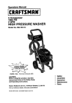
OWNER'S
MANUAL
CRRFTSMIIN
5.0 Horsepower
1800 PSI
2.0 GPM
High Pressure Washer
Model No:
919.679180
• Safety
• Assembly
• Operation
• Maintenance
WARNING: Before using this
product,
read this manual
and follow all Safety Rules
and Operating Instructions.
• Parts List
• Fran£_ais
Sold
MGP-e7918GA
5/26/S9
by Sears
Canada,
Inc.,
Toronto,
Ont.
M5B2B8
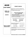
TABLE OF CONTENTS
Warranty
............................................
Safety Guidelines
2
..............................
Service and Adjustments
3-4
Storage
................ 13-14
..................................................
14
Assembly
...........................................
5-6
Troubleshooting
Operation
...........................................
6-9
Parts ................................................
16-27
EPA Codes ......................................
28-29
Product
Specifications ......................
Maintenance
......................................
FULL ONE YEAR WARRANTY
10
10-12
....................................
How to Order Parts ................ Back Cover
ON CRAFTSMAN
HIGH PRESSURE
WASHER
For one year from the date of purchase, when this Craftsman High Pressure Washer is maintained
and operated according to the instructions in the owner's manual, Sears will repair, free of charge,
any defect in material and workmanship.
If your Craftsman PressureWasher is used for eommerieal or rental purposes, this warranty
applies only for 90 days from the date of purchase. If this washer is used for rented purposes this
warraty applies for only 30 days from the date of purchase.
FULL TWO YEAR WARRANTY
ON CRAFTSMAN
ENGINE
For two years from the date of purchase, when this Craftsman engine is maintained and operated
according to the instructions in the owner's manual, Sears will repair, free of charge, any defect in
material and workmanship.
If your Craftsman engine is used for commerical or rental purposes, this warranty applies only for
one year from the date of purchase. This warranty does not cover expendable items such as spark
plugs and air filters, which become worn during normal use.
Repairs necessary because of operator abuse or negligence, including damage resulting from no
water being supplied to pump or failure to maintain the equipment according to the instructions
contained in the owner's manual, are not covered under warranty.
WARRANTY SERVICE IS AVAILABLE BY RETURNING THE HIGH PRESSURE WASHER TO THE
NEAREST SEARS SERVICE CENTER THROUGHOUT THE UNITED STATES. This warranty gives you
specific legal rights and you may also have other rights, which vary from state to state.
Sold
by Sears
Canada,
15
Inc.,
2
Toronto,
Ont.
M5B2B8
SAFETY GUIDELINES
- DEFINITIONS
This manualcontainsinformation
that is importantfor you to know and understand.This informationrelates to protecting
YOUR SAFETYand PREVENTINGEQUIPMENTPROBLEMS.Tohelp you recognizethis information,we usethe symbols
below. Pleaseread the manualand pay attentionto these sections.SAVETHESE DEFINrrloNS/INSTRUCTIONS.
A WARNING
indicates a potentially
situation which, if not avoided, _
death or serious iniurv.
hazardous
result in
A, DANGER indicates an imminently hazardous
situation which, if not avoided, will result in
death or serious iniurv.
A CAUTION indicates a potentially hazardous situation
which, if not avoided, may resultin mi
t
iniurv.
t0/2197
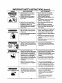
IMPORTANT
SAFETY INSTRUCTIONS
Improper operation or maintenance of this product could result in serious injury and property damage. Read and understand
warnings and operating instructions before using.
HAZARD
RISK OF EXPLOSION
OR FIRE
WHAT CAN HAPPEN
• Spilled gasoline and its vapors can
become ignitedfrom cigarette
sparks, electrical arcing,exhaust
gases, and hot enginecomponents
such as the muffler.
• Heat will expand fuel in the tank
which could result in spillage and
possible fire explosion.
• Operating the pressure washer in an
explosive environment could result
in a fire.
•
Materials placed against or near the
pressure washer can interfere with
itsproper ventilationfeatures
causing overheatingand possible
ignitionof the materials.
all
HOW TO PREVENT IT
• Shut off engine and allow itto cool
before adding fuel to the tank.
D
Use care in filling tank to avoid
spilling fuel. Move pressurewasher
away from fuelingarea before
startingengine.
Keep maximum fuel level V2below
top of tank to allow for expansion,
Operate and fuel equipment in well
ventilated areasfree from obstructions. Equip areas with fire
extinguishers suitable for gasoline
fires.
Never operate pressure washer in an
area containing dry brush or weeds.
Improperlystored fuel could lead to
accidental ignition. Fuel improperly
secured could get into the hands of
childrenor other unqualifiedpersons.
Store fuel in container approvedfor
gasoline, in a secure location away
from work area,
Breathing exhaust fumes will cause
serious injury or death.
Operate pressure washer in a well
ventilated area. Avoid enclosed areas
such as garages, basements ,etc.
Never operate unit in a location
occupied by humans or animals.
Some cleaning fluids contain substances which could cause injury to
skin, eyes, or lungs.
Use only cleaning fluids specifically
recommended for high pressure
washers. Follow manufacturers
recommendations.
RISK TO BREATHING
3
IMPORTANT
HAZARD
RISKOF UNSAFE
OPERATION
SAFETY INSTRUCTIONS
WHAT CAN HAPPEN
Unsafe operationof your pressure
washer could lead to serious injury
or death to you or others.
• The spray gun/wand is a powerful
cleaningtool that could look like a
toy to a child.
Reactive force of spray will cause
gun/wand to move, and could cause
the operatorto slip or fall, or
misdirect the spray.Improper control
of gun/wand can result in injuriesto
self and others.
RISK OF INJURY FROM
SPRAY
• High velocityfluid spray can cause
objects to break, propelling particles
at high speed.
• Ught or unsecured objects can become
hazardousprojectiles.
(cont'd)
HOW TO PREVENT IT
• Become familiar with the operation
and controlsof the pressurewasher.
• Keep childrenaway from the
pressure washer at all times.
• Never defeat the safety features of this
product.
• Do not operate maohine with missing,
broken, or unauthorizedparfs.
• Never leave wand unattended while
unit is running.
• Keep work area free of obstacles.
• Stand on a stable surface and grip gun/
wand firmly. Expect the gun to kick
when triggered.
• Always wear ANSI approved Z87 safety
glasses. Wear protective clothing to
protect againstaccidental spraying.
Never point wand at, or spray people or
animals.
I= Always secure trigger lock when wand
is not in service to prevent accidental
operation.
• Never permanentlysecuretriggerin pull
back (open) position.
RISK OF
ELECTRICAL
SHOCK
RISK OF FLUID INJECTION
RISK OF CHEMICAL BURN
• Spray directed at electrical outletsor
switches, or objects connected to an
electrical circuit, could result in a fatal
electrical shock.
• Unplug any electrically operated
product before attempting to clean it.
Direct spray away from electric outlets
and switches.
Your washer operates at fluid
pressures and velocitieshigh enough
to penetrate human and animal flesh,
which could result in amputation or
other serious injury. Leaks caused by
loose fittings or worn or damaged
hoses can result in injection injuries.
DO NOT TREATFLUID INJECTIONAS
A SIMPLE CUT! See a physician
immediately!
• Never place handsin front of nozzle.
• Direct spray away from self and others.
• Make sure hose and fittings are
tightened and in good condition. Never
hold onto the hose or fittings during
operation.
• Do not allow hose to contact muffler.
• Never attach or remove wand or hose
fittings while system is pressurized.
Relieve system pressure before
attemptingmaintenance or disassembly of equipment.
• Use only hose and high pressure
accessories rated for 1800 PSI service.
• To relieve system pressure, shut off
engine, turn off water supply, and pull
gun trigger until water stops flowing.
• Use of acids, toxic or corrosive
chemicals, poisons, insecticides, or
any kind of flammable solvent with this
product could result in serious injury
or death.
• Do not use acids, gasoline, kerosene, or
any other flammable materials in this
product. Use only household
detergents, cleaners and degreasers
recommended for use in pressure
washers.
• Wear protective clothing to protect
eyes and skin from contact with
sprayed materials.
4
IMPORTANT
SAFETY INSTRUCTIONS
(cant'd)
HAZARD
WHAT CAN HAPPEN
HOW TO PREVENT IT
RISK OF HOT SURFACES
• Contact with hot surfaces,such as
engines exhaust components, could
result in sedous bum.
• Duringoperation,touch onlythe control
surfaces of the pressure washer. Keep
children away from the pressurewasher
at all times. They may not be able to
recognizethe hazards of this product.
Symbols
Owner's Manual
"_
Fuel
i
['_[
Choke
The powerful spray from your pressure washer is capable of causing damage to fragile surfaces such as: wood, glass,
automobile paint, auto strippingand trim, and delicate objects such as flowers and shrubs. Before spraying, check the
item to be cleaned to assure yourself that it is robust enough to resist damage from the force of the spray. Avoid the
use of the concentrated spray stream except for very strong surfaces like concrete and steel.
Operating unit with water supply shut off without flow of water willresult in equipment damage. You shouldnever run
this pressure washer for more than 2 minutes without pulling the tdgger to allow cool water to enter the pump and the
heated (recirculated) water to exit. Running the pressure washer with water supply shut off will void your warranty.
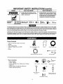
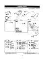
Carton
Contents
Main Unit pressure
Handle
washer
with wheels
High Pressure Hose
Chemical Pickup Hose and Filter
Gun
Wand
Main
Unit pressure
with wheels
Handle
High
Pressure
Hose
©
Chemical
•
washer
Pickup Hose and Filter
Gun
and
Wand
Bag Containing
Video Cassette
Owner's Manual
Video
Nozzle Cleaning Kit and Replacement
O-Rings
Engine Oil
Rubber Isolator and Mounting Hardware
Handle Mounting Hardware
Cassette
Owner's
Manual
Nozzle Cleaning Kit
©
Engine
Oil
Handle
Mounting
Hardware
Rubber
O
Replacement
5
][
_
Mounting
O-Rings
Isolator
and
Hardware
,
Tools Required
for Assembly
Adjustable wrench
Allen wrench
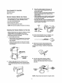
Remove
Pressure
Washer from Carton
• Open carton from the top. Locate and remove from
box the handle, gun, wand, videotape, and oil.
• Cut carton along doffed lines.
• Remove all carton inserts.
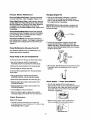
Mount the rubber isolator to the frame. To
mount isolatorplace threaded end of bolt
throughthe washer.
• Next with washer on bolt place threaded end of
bolt throughthe largerhole in bottom of the
rubberisolator.
• Place threaded portion of bolt through the same
hole locationthe wood plank was mounted to
on the pressurewasher.
• Next place the tee nut over the threaded portion
of the bolt and usethe allen wrench provided to
tighten isolatorto the frame.
• Roll unitthroughopening in carton.
NOTE: The hose is located at the bottom of the box.
TEENtrr
r[
Preparing
the Pressure
]
WASHER
PRESSURE
FRAME
Washer for First Use
W/i_HER
Note: Included with your pressure washer is a video
cassette tape on how to prepare your unitfor
operation. It is recommended you view this tape
before performing the nextsteps.
1. Insert handle onto frame.
_
-_.
-- EOL4TOR
BOLT
4, Connect wand extensionto gun. To tighten, turn
knob in clockwise direction. Hand tighten.
• Insert knobs into the threaded slot in front of the
frame handle and tighten by turning in a clockwise direction.
• Slide bolts into the slot in the side of the frame
handle and tighten the nut by turning in a clockwise direction.
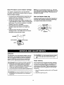
5. Remove tie wrap off of high pressure hose,
Unwind high pressure hose and attach the
threaded end to the gun. Tighten with adjustable
wrench.
Insert bolt and
tighten lock nut,
Tighten knob in
_.___
clockwise
direction.
6. Connect high pressure hose to outlet on
pressure washer and hand tighten firmly.
Connect chemical pickup hose to hose barb
on pump.
2. Using an adjustable wrench, remove nut from
bolt that attaches board to frame. Remove wood
plank from the frame of the unit. Discard bolt and
board.
CHEMICAL-HOSE
HIGH
PRESSURE
HOSE
NOTE: Always keep hose away from engine muffler.
6
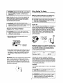
Pull the cord under the wire bracket to the
right of the wire loop.
Lift the pull cord handle up and slide the cord
to the left sliding the cord into the wire loop.
Next slide handle behind the wire bracket to
the left of the wire loop.
Engine recoil will pull the cord into its final
position.
7. Place assembled gun and wand on pressure
washer holder.
Checklist
Before going any further please review the following:
• Be sure you have completed assembly instructions.
• Double check all fittings to be sure they are tight.
IMPORTANT: Before any attempt to start your pressure washer be sure to check engine oil (See Operation under Adding EngineOil.)
8, Place pull cord intothewire bracket holder.
Pull the cord under the wire bracket to the right
of the wire loop.
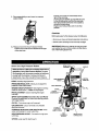
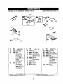
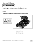
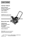
Know Your High Pressure
SPRAY GUN
ASSEMBLY
Washer
HANDLE
Read this Owner's Manual and Safety Rules before
operation of your High Pressure Washer Compare
this illustrationwith our pressure washer to familiarize
yourself with the location of various controlsand
adjustments. Save this manual for future reference.
RECOIL
HIGH PRESSURE
PUMP-
HOSE_
Develops high pressure.
PRESSURE REGULATOR- Allows you to adjust the
pressure of the outlet stream.
OIL FILL
ENGINE RUN/STOP SWITCH- Sets engine in starting
mode for recoil starter -- Stops running engine.
ENGINE
RECOIL STARTERmanually.
Used for starting the engine
SPRAY GUN ASSEMBLY (Contains Gun and Wand)Controls the application of water onto cleaning surface
with trigger device.
PUMP
OIL FILL- Port where engine oil is poured.
GAS TANKJCAP- Cap is removed and unleaded
gasoline is poured.
CHEMICAL
INJECTOR
TUBE & FILTER
CHEMICAL INJECTION TUBE AND FILTER- Mixes
water and detergent in outlet water flow.
HIGH PRESSURE
sure hose.
CHOKE-
OUTLET-
Connection
HIGH
PRESSURE
OUTLET
for high pres-
Lever used for starting unit.
7
WATER
INLET
CONNECTION
Before
to operate equipment until you have read Owners
for Safety,
Operation,
and Maintenance
A Manual
ARNING:
Read Owner's
Manual.
Do not attempt I
Instructions.
To operate the engine you will need to do the following.
I
I
every start. Runningengine low of oilor out of oil
I h, CAUTION:
Always
check
engine oil level before I
could resultin
sedous
damage.
A, WARNING: Never adjust spray pattern when
spraying. Never put hands in front of spray nozzle to
adjust spray pattern you could be injured.
Your Pressure
The Engine
Note: Yourpressure washer pump is a sealed pump,
you should never have to add or change the oil.
Note: Included with your unit is a video cassette that
demonstrates how to operate your pressure washer.
If you have a video cassette recorder you should to
view the video before operation.
Stopping
Starting
Washer
& CAUTION: Do not run pump without the water
]
supply connected and turned on. Failureto do so
will result in pump damage.
I
Engine Oil
Your unit has been shipped without oil in the engine. A
bottle of SAE 30 weight oil is included in the carton.
Remove oil dip stick located on top of the engine. Oil
capacity is about 20 ounces of oil. The oil dip stick is
clearly marked with a line that tells you when unit has
enough oil To check oil, place dipstick into oil fill.
Tighten dipstick then remove. Do not fill above this
point. Pour slowly.
• Move throttle control to the stop positionto turn
pressure washer off.
• Simply shuttingOFF engine willnot release pressure
in the system. After engine has stopped, squeeze
the trigger on the spray gun for about 3 seconds to
relieve pressure. Spray stream will decrease in
length.
IMPORTANT: This unit is equipped with
valve. If unit is allowed to run for several
without pressing the trigger on the spray
drops of water may be released through
cool the unit. This small amount of water
the bottom of the pump,
a thermal relief
minutes
gun, several
this valve to
will drip from
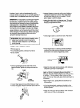
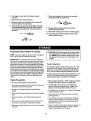
NOTE: When adding oil to the engine crankcase, use a
high quality detergent oil classified "For Service SF, SG,
SH, rated SAE 30 weight, Use no special additives.
Select the oil's viscositygrade according to your expected operatingtemperatures.
colder <..........
Synthetic 5W-30
40°F ......
I
> warmer
SAE 30
Although multi-viscosityoils (5W30, lOW30, etc.)
improve starting in clod weather, these multi-viscosity
oils will result in increased oil consumption when used
above 40°F Check your engine oil level more frequently
to avoid possible damage from running low on oil. Oil
sump capacity is 20 ounces.
Gasoline
Your pressure washer engine is 4 cycle. Use unleaded
fuel only.
A, allow
AUTION:
Do fuel
not expansion.
overfillthe fuel tank. Always
room for
explosion and injury,never fill fuel tank when
is runningor
hot.
notindoors.
smoke or
A, engine
ARNING:
Never fill
fuelDo
tank
Tohave
avoid
open flame when fillingfuel tank.
• Squeeze trigger on pressure washer wand to relieve
air pressure caused by turning on the water. Water
will spew out of the gun in a thin stream. This will
make it easier to start the engine.
Use clean, fresh, regular unleaded gasoline with a
minimum of 85 octane. Do not mix oil with gasoline. If
unleaded fuel is unavailable leaded fuel may be used.
IMPORTANT: It is important to prevent gum deposits
from forming in essential fuel system parts such as
the carburetor,fuel filter hose or tank during storage.
Also, experience indicates that alcohol-blended fuels
(calledgasohol or usingethanol or methanol)can
attract moisture which leads to separation and formation of acids during storage. Acidic gas can damage
the fuel system of an engine while in storage. To avoid
engine problems, the fuel system should be emptied
before storage of 30 days or longer.Never use engine
or carburetor cleaner products in the fuel tank or
permanent damage may occur.
• Engage the safety latch on the spray gun. This locks
the trigger in place and keeps you from accidentally
sprayinga high pressure stream.
SAFETY
.LATCH
!
water
I_
source
turned
on and connected
to
pressure washer. Failure to do so will cause
CAUTION: Never start pressure washer without
pump damage.
To Start Your Pressure
I
• On the engine there is a choke/run
to the choke position.
I "_..ml
lever. Place lever
I o_1
I
Washer
• Remove gas cap.
• Add unleaded gasoline, slowly,to fuel tank.
• Do not overfill.
• On the engine there is a throttle control lever.Place
throttle to the rabbit position. Always start engine
with throttle in the rabbit (high speed) position.
• Connect garden hose to the water inlet on the
pressure washer. Tighten by turning counterclockwise.
• Grasp the starter grip and pull slowly until resistance
isfelt,then pull firmly to start engine.
PUMP
INLET
NOTE: If engine does not start right away, squeeze the
triggeron the gun to relieve air pressure caused by
turning on the water. Water will spew out of the gun in a
thin stream. This will make it easier to pull start the
engine. If more than five pulls, place choke level back to
run position.
• When engine starts, gradually move choke lever to
RUN position.
• Connect high pressure hose to discharge on pump.
• Connect the garden hose to the water spout and turn
water supply on.
• For hot engine restarts, make sure throttle is in the
rabbit (high speed) position and the choke lever is in
the RUN position.
• Grasp the starter grip and pull slowly until resistance
is felt, then pull firmly to start engine.
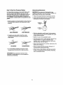
How To Use Your Pressure
Washer
On the end of your spray gun is a nozzle that you can
slide forward and backward and that you can also
twist from side to side. With the adjustable nozzle you
can adjust the spray pattern to either high pressure
or low pressure. You can also adjust the spray so it is
concentrated in a stream pattern or expanded into a fan
pattem.
Using Soaps/Chemicals
IMPORTANT: Use soaps and chemicals that are
designed specifically for use with pressure washers, To
apply soaps/chemicals follow these steps:
• Preparethe soap/chemical as required by yourjob.
• Insertsoap/chemical line intoyour container (soap/
chemicalsand containernot included),
• Slide the nozzle in a forward position to draw chemical
and achieve low pressure. Pull nozzle back for high
pressure.
CHEMICAL
HOSE --
CHEMICAL
HIGH PRESSURE
LOW PRESSURE
• Slide the adjustable nozzle forward to low pressure
mode. Soap/chemicals cannot be applied with nozzle
in high pressure position.
• To adjust your spray pattern twist the nozzle
clockwise for fan spray or counterclockwisefor
stream spray.
• Review the use of the adjustable nozzle.
• Connect garden hose to water inlet (see "To Start Your
Pressure Washer" on page 9). Check that high
pressure hose is connected to spray gun and pump
(see Assembly), and start engine.
• Apply soap/chemicals to dry surface, starting from the
bottom and working up.
FAN SPRAY
STREAM SPRAY
• Allow the soap/chemicals
to soak in between 3-5
minutes before washing and dnsing.
• For most effective cleaning, keep spray nozzle
between 8 and 24 inches from cleaning surface.
• When rinsingon high pressure, start at lower portion
of area to be washed and work upward, using long,
even, overlapping strokes.
IMPORTANT: If you get spray nozzle too close,
especially on high pressure, you may damage the
surface you are cleaning.
10
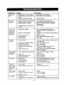
CUSTOMER RESPONSIBILITIES TABLE
MAINTENANCE TASK
Beforeeach use
Every25
hoursor veadv
Every50
houmorveadv
Every100
hoursor veadv
PRESSURE WASHER
Check/clean inletscreen,
Check hiah pressurehose.
Check soao and chemicalhose and filter
Check gun and wand for le_ks,
x
x
x
x
Purge oumoof air and contaminants
x
ENGINE
Gheck0il level
Char_aeengine oil
Clean air cleaner and orecleaner
ClearVreolacestark clua
Clean enoine muffler & flnoer auard
IPreDarefor storaee
Product
x
}_
x
x
x
Precare unitfor storaneif it is to remainidlefor Ionaerthan 30 davs.
Specifications
General
The warranty of the high pressure washer does not
cover itemsthat have been subjected to operator
abuse or negligence. To receive full value from the
warranty, operator must maintain high pressure
washer as instructed in this manual.
Pressure Washer Specifications
Flow Rate
I Pressure
Cleaning Units (psi x GPM)
2.0 GPM
1600
3600
Some adjustments will need to be made periodically to
maintain your high pressure washer.
Engine Specifications
RPM
Rated Horsepower
Spark Plug Gap
Gasoline Capacity
Oil (22 oz. capacity)
Recommendations
Once a year you should clean or replace the spark
plug, and clean or replace the air filter, and thoroughly
check the gun and wand assembly for wear. A clean
spark plug and clean air filter assure proper fuel-air
mixture and help your engine run better and last longer.
3600
5.0
%030" (0.76mm)
Your pressure washer pump is a sealed pump; you
should never have to add or change the oil.
1.5 quarts
SAE 30 weight
NOTE: Over time the o-rings in the gun assembly
become worn. Attached to your owners manual is a
replacememt o-ring and split backup ring.
O-ring_._
_----
-_"_
11
Split Backup
_v
Ring
Pressure
Washer
Maintenance
Changing
Check and Clean Inlet Screen: Examine inletscreen
on pump inlet fitting. Clean if clogged; replace if tom.
Engine Oil
• Change oil while engine is stillwarm. Preferably
drain oil from top of engine as illustrated below.
Drain oilwith air cleaner side up, Oil can be drained
from engine bottom if necessary.
Check High Pressure Hose: High pressure hose can
develop leaks from wear, kinking,abuse. Inspect hose
each time before use. Check for cuts, leaks, abrasions
or bulgingof cover, and damage or movement of
couplings. If any of these conditionsexist, replace hose
immediately.
IMPORTANT: Beforetipping engine or equipment to
drain oil, drain fuel from tank by runningengine until
fuel tank is empty.
Check Chemical/Soap Hose: Examine the chemicaV
soap hose and clean if clogged. Hose should fit tightly
on pump fitting. Check for leaks and tears. Replace
filter or hose if either is damaged.
Cleaner
e
Check Gun and Wand: Examine hose connection to
gun making sure it is secure. Test trigger by pressing it
and making sure it springs back into place when you
release it.
Pump Maintenance
• Todrain oilfrom bottom of engine, remove drain
plug as illustrated below. Allow oil to drain and
replace drain plug. Remove dipstick and refill with
new oil of recommended grade. Start and run engine
at idle for 30 seconds.
(Changing Pump Oil)
Your pressure washer pump is a sealed pump, you
should never have to change oil.
OIL DRAIN
PLUG
Purge Pump of Air and Contaminants
318" SQUARE
To remove the air from the pump, follow these steps:
• Set up the pressure washer as described in
Assembly section and connect the water supply.
P|PE
• Stop engine. Wait 30 seconds and re-check oillevel.
If required, add oil to bring level to FULL mark on
dipstick,
• Remove the wand extension from the spray gun.
• Pullthe trigger on the gun and hold.
To remove the contaminants from the pump, follow
these steps:
• Set up the pressure washer as described in
ASSEMBLY section, connect the water supply.
• Remove the wand extension from the spray gun.
Check
• Start the engine accordingto instructionsin the
OPERATIONsection.
Engine
-- Finger
Guard/Muffler
• Do not clean engine with a forceful spray of
water because water could contaminate fuel system.
With a brush or cloth, clean any debris from finger
guard after every useto prevent engine damage
caused by overheating.
• Start the engine according to instructionsin the
OPERATIONsection.
• Pullthe trigger on the gun and hold.
• When the water supply is steady and constant,
disengage triggerand refasten the wand extension.
Engine
Check
Maintenance
Oil Level
• Before running engine, clean muffler area to
remove all grass and combustible debris.
• Oil level should be checked prior to each use
or at least every 5 hours of operation. To check oil see
Adding Engine Oil on page 9.
12
Clean Pre-Cleaner
and Air Cleaner
Cartridge
NOTE: Do not use petroleum solvents,e.g., kerosene,
which willcause the cartridge to detedorete. Do not use
pressurizedair to clean cartridge. Pressurized air can
damage the cartridge.
Your engine is equipped with an oval dual element
air cleaner: the two elements include a foam pre-cleaner
and an air cleaner cartridge.
• To remove the air cleaner element, loosen two cover
screws and lift cover. Carefully remove foam precleaner and air cleaner cartridge.
• To clean pre-cleaner and air cleaner cartridge,wash
in liquiddetergent and water. Allow to dry thoroughly
before using. Do not oil the precleaner or cartridge.
Replace if very dirty or damaged.
• After cleaning the pre-cleaner and air cleaner
cartridge, replace pre-cleaner on air cleaner car
tridge.
• Install air cleaner assembly (pre-cleaner and
cartridge) in base. Then installcover on air cleaner
and tighten screws securely to base.
Clean and Replace
Spark Plug
Change the spark plug every I00 hours of operation or
once each year, whichever comes first. This will help
your engine to start easier and run better.
.030" (0.76 MM)
RESISTOR
oo.vER
PRE-CLEANER
_CARTRIDGE
BASE
Carburetor
I
The carburetor of your high pressure washer is pre-set
at the factory. The carburetor should not be tampered
with. If you pressure washer is used at an altitude in
excess of 5000 feet consult with your nearest Sears
Service Center regarding high altitude set changes.
IA
I
load on the engine and could shorten engine
CAUTION: Low engine speeds impose a heavy I
life.
Nozzle
Cleaning
If the nozzle becomes clogged with foreign materials,
such as dirt, excessive pressure may develop. If the
nozzle becomes partially clogged or restricted, the
pump pressure will pulsate. Clean the nozzle immediately using the nozzle kit supplied and the following
instructions.
A CAUTION: Engine speed was properly adjusted
at the factory and should require no additional
adjustment. Do not attempt to change engine
speed, If you believe the engine is running too fast
or too slow, take your pressure to a Sears
Authorized Service Center for repair and adjustment.
1. Shut off the pressure washer and turn off the water
supply.
,& WARNING:High engine speeds are dangerous and
increase the risk of personal injury or damage to
equipment.
2,
13
Disconnect
spark plug wire.
3. Pull tdgger on gun handle to relieve any water
pressure.
4. Disconnect the wand from the gun.
7. Direct water supply into nozzleend to backflush
loosened particles for 30 seconds.
5. Remove nozzle from the the end of the wand with
the 2ram allen wrench provided.
6. Clean the nozzle usingthe nozzle cleaner provided
or a straightened paper clip. Insert intothe nozzle
end and work back and forth untilobstructionsis
removed.
8. Reassemble the nozzle to the wand. Tightan
securelyto prevent leaks.
9. Reconnect wand to gun and turn on water suppply.
10. Start pressure washer and place wand into high
pressure setting to test.
Preparing
Pressure
Washer
for Storage
sure water supply is turned on and flowing to the
unit. NEVER rununit withoutwater supply running
pump.
Failureto
do so willcause
pump
l a, through
CAUTION:
While
while preparing
the engine
make
damage.
NOTE: If you do not plan to use your unit for 30 days or
more, unit should be prepared for storage.
IMPORTANT: It is important to prevent gum deposits
from forming in essentialfuel system parts such as the
carburetor,fuel filter hose or tank during storage. Also,
experience indicates that alcohol-blended fuels (called
gasoholor using ethanol or methanol)can attract moisture which leads to separation and formation of acids
during storage. Acidic gas can damage the fuel system
of an engine while in storage. To avoid engine problems,
the fuel system should be emptied before storage of 30
days or longer.Never use engine or carburetor cleaner
products in the fuel tank or permanent damage may
occur.
Pump Preparation
This pressure washer should be stored in such a way
to protect it from freezing. Do not store this unit outdoors or in an area where temperatures will fall below
32 ° E This can cause extensive damage to this unit.
If unit has to be stored under freezing conditions a nontoxic R.V.anti-freeze should be put in the pump according to steps below to protect from freezing.
Engine Preparation
• Be sure engine switch is in "OFF" position and spark
plug wire has been removed from spark plug.
• First add a fuel stabilizer to the fuel tank.
• Pull the trigger on the spray gun to release the
pressurein the high pressure hose. Detach high
pressure hose and garden hose from the unit.
• Run pressurewasherforafull5minutestoailowfuel
stabilizer to enter the fuel system.
• Next shut off engine and disconnect the water
supply.
• Pullthe recoil on the engine 4 to 6 times to discharge
remaining water in pump.
• Disconnect the spark plug wire and remove the spark
plug.
• Add one teaspoon
hc4e.
• Tip the unit on the end with the water inlet fitting
pointing upward.
of oil through the spark plug
• If unit will be stored where temperturee fall below
32°F, pour approximately 1/4 cup of non-toxic R.V.
anti-freeze down the fitting where the water hose
attaches to the pump.
• Place rag over spark plug hole and pull the recoil a
few times to iubricate the combustion chamber.
• Set unit upright and pull starter handle on engine 4 to
6 times to circulate anti-freeze in pump until antifreeze is discharged from the pump.
• Replace the spark plug, but do not connect the spark
plug wire.
14
SYMPTOM
Engine
won't
start
Won't Draw
Chemical
Pump running
normally but
pressure does
not achieve
rated values
CAUSE
1. Engine
throttleis in "OFF"
SOLUTION
Position.
2. Choke lever has not bean placed to
choke,
3. Pressure buildup after initial use.
1. Slide throttle to "Run" position.
2. Slide choke lever to choke position.
1. Nozzle not in chemical draw position.
2. Chemical screen is obstructed.
3. Chemical screen not working.
1. Push nozzle forward at end of wand.
2. Check chemical screen; clean if obstructed.
3. Make sure chemical screen is submerged in
chemical/water.
4. Chemical injector orifice obstructed
or stuck.
4. Check and clean.
1. Water supply restricted.
1. Check water supply and filter screen for.
blockage. Check hoses for blockage, kinks,
leaks, etc.
2. Pull nozzle at end of wand back to the high pressure
position.
3. Check and replace.
4. Check that hoses and ftttings are airtight.
5. Clean nozzle.
2. Nozzle is in low PSI position.
3. Nozzle incorrect or worn.
4. Pump sucking air.
5. Nozzle blocked.
Fluctuating
Pressure
Check that hoses and fittings are airtight. Purge air
from garden hose.
2. Clean. Check filter frequently.
3. Check and replace.
4. Check hose for kinks.
5. Check flow available to pump. Check for
excessive heat, 145o F or above.
6. Clean inlet and discharge valve assemblies.
Replace if damaged.
1. Pump sucking air.
1.
Garden hose inlet strainer clogged.
3. Worn Seals or Packing.
4. Inadequate water supply.
5. Foaled or dirty inlet or discharge
valves.
2,
6.
Pressure drops
after period of
normal use
Leaky discharge
3. Depress trigger gun.
hose.
1. Nozzle clogged, partially obstructed.
2. Nozzle worn.
3. Valves wom, dirty or stuck.
4. Worn piston pecking.
1. Check connection. Replace if cracked or
punctured.
2. Clean or replace.
3. Check and replace.
4. Check and replace.
Pump noisy
1.
2.
3.
4.
1.
2.
3.
4.
Presence of
water in oil (oil
milky); Water
dripping from
pump.
1. High humidity.
2. Piston packing and oil seal worn.
1. Change Oil.
2. Check and replace oil seals.
Water dripping
from pump
1. Fittings Loose.
2. O-rings of piston guide or retainer
worn.
3. Piston packing worn.
1. Tighten.
2. Check and replace.
3. Check and replace.
Oil Dripping
1. Oil seal worn
2. Loose drain plug or wom drain plug
o-ring.
1. Check and replace
2. Tightendralnplugorrepisceo-dng.Donotovertorque.
Water too hot.
Pump sucking air.
Valves dirty or worn.
Wom bearings.
15
Reduce temperature below 63° C or 145° F.
Check that hoses and fittings are airtight.
Check, clean or replace.
Check and replace if necessary.
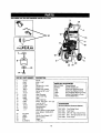
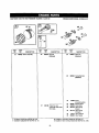
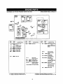
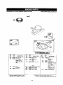
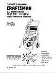
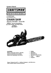
CRAFTSMAN
2400
PSI HIGH PRESSURE
WASHER 919.679180
3
19
24
8
5
20
22
21
REF NO. PART NUMBER
DESCRIPTION
1
2
3
4
5
6
7
8
10
11
12
13
14
15
16
17
19
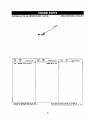
900
Handle
Knob - 5/16"
PARTS NOT ILLUSTRATED
Gun
MGP-679180
Owners Manual
Tire Semi (7 x 1 3/4")
NC3"OO1
Nut Pal 1/2"
Nozzle Cleaning Kit
F191
Rubber Foot, Hollow
Screw, Hex-Engine to Pump
F196
Tee Nut 5/160" x 3/4"
Screw, Hex-Engine to Pump
16087
Frame
Nut Flanghead-Engine to Pump
F074
Hose, Chemical
Washer Flat-Engine to Pump
16505
Thermal Relief Valve
Lance, Multi-Reg
Hose
Decal Craftsman
Screw - Hex 5/16" - 18 x 1LG
Lock Nut 5/16"
ACCESSORIES
Screw HHC, 5/16"
(Not Included with Pressure Washer)
Decal Operation
Handle Grip
919.76430
FlooHSiding Brush
Engine (Refer to Engine Break919.76431
Fixed Brush
down (Model 12F802-2017)
919.76450
25Ft. 3/8" high pressure hose
Pump
919.76451
50Ft.
3/8" high pressure hose
Garden Hose Adapter 1/2"
919.76484
Turbo
nozzle
3/8" Coupling
Washer
O-Ring Kit
17715
C042
H128
17709
W137
16371
W131
17713
H140
N130
H040
17569
F064
F469
17712
17913
17367
.....
20
21
22
PK17908
16829
F504W
23
24
Fl12
AL-650015
16
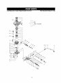
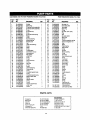
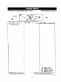
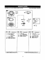
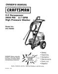
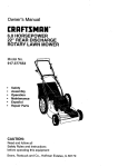
CRAFTSMAN
2400
PSI HIGH PRESSURE WASHER
919.679180
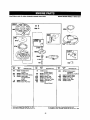
PUMP BREAKDOWN
3
s-_O
8
IS
_
41
47 48
10
4_
17
MODEL PK-17908
CRAFTSMAN
2400
PSI HIGH PRESSURE WASHER 919.679180
Ref.
Part
No.
No.
_
PUMP BREAKDOWN
_v.
1
FA-15203000
Oil Seal
1
2
3
4
5
6
7
8
9
10
11
12
13
14
15
16
17
18
19
20
21
22
23
24
25
26
27
28
FA-13301000
FA-57015402
FA-52045401
FA-15001600
FA-52045302
FA-15062200
FA-52067400
FA-57138700A
FA-15000900
FA-17400200
FA-16900200
FA-57138900
FA157130600
FA-57133100
FA-15024000
FA-57137800
FA-15001500
FA--57137401
FA-52069100
FA_57136300
FA-52052100
FA-18102500
FA-15000100
FA-15064200
FA-52022500
FA-15060500
FA-23732300A
Elastic Ring
Oil vented valve assembly
Oil vented valve assembly
O-dng
Oil vented cap
O-dng
Oil vented valve spring
Range
O-dng
Top disc beadng
Needle bearing
Wobble plate
Cap
Lower disc bearing
O_ing
Carter
O-dng
Oil sight glass
Connection ring nut
Inlet extension
filter gasket
under cap
O-ring
O-dng
Valve assembly
O-dng
Manifold
1
1
1
1
1
1
1
1
t
3
2
1
1
1
1
1
3
1
1
1
1
1
3
3
6
4
t
29
30
FA-15065000
FAll 0801900
CLdng
Screw
1
1
31
32
33
34
35
36
37
FA-50136200
FA-17600300
FA-15001400
FA-52036700
FA-1500(_o00
FA-50139700
F,t_52032700
Chemical spring
Chemical ball
O-ring
Chemical Injector body
O-ring
Chemical Injector screw
Balance flow valve
1
1
1
1
I
1
1
38
39
40
41
42
43
44
FA-52032801
FA-52032500
FA-15062600
FA-15001300
FA-52032601
FA-18104600
FA-10205200
Spring
Injector nozzle
O-dng
O-ring
Injector nipple body
under cap
Screw
1
1
1
2
1
1
4
Ref.
Part
No,
No-
_
45
46
47
48
49
50
51
52
53
54
55
56
57
58
59
60
61
FA--52234500
FA-52068000
FA-52052302
FA-15100100
FA-15001100
FA-52036501
FA-52038300
FA-17600900
FA-52070600
FA-15101700
FA-5223530t
FA-23731400
FA-52070700
FA-52033600
FA.-52033800
FA-52045201
FA-19200400
By-pass pin
Valve seat plate
Valve seat
Back ring
O-dng
By-pass valve body
Rug
Ball
By-pass piston
Back ring
Spacer
Pressure regulator spring
Pressure regulator nut
Ring
Piston
Piston Spring
Head screw
1
1
t
1
1
t
1
1
t
t
1
1
1
3
3
3
3
62
63
64
65
66
67
68
69
70
71
72
73
74
FA-15665600
FA-t 5202400
FA-52038801
FA-15001800
FA-57t 37400
FA-t 550t 8C0
FA-15065300
FA-52068400
FA-52068101
FA-52068300
FA-52068200
FA-52030202
FA-10204100
O-ring
OilSeal
Brass bushing
O-ring
Oil fill cap
High pressure seal
O-dng
Valve seat
Valve plate
Spnng valve
Valve cage
Pump head
Screw
2
3
3
3
1
3
3
6
6
6
6
1
5
75
76
77
78
79
84
85
86
87
FA-15000700
FA-12406500
FA-15061800
FA-57136200
FA-52045100
FA-5206930 t
FA-13500500
FA-16003000
FA-10801600
O-dng
Washer
O-dng
Outlet extension
Cap
Washer
Pin
Beadng
Screw
1
1
2
1
1
3
1
1
1
88
89
FA-15000300
FA-52036800
O_ng
Hose barb for
1
90
FA-15611200
chemical injector
Chemicat hose
1
1
91
FA-52037200
Chemical hose filter
1
PARTS KITS
Oil Seal Kit
Bearing Kit
Valve Kit
Piston Kit
Water Packing Kit
Unloader Kit
Chemical Injector Kit
FA-YK157015402
FA-YK157138900
FA-YK152022500 01
FA-YK152033600
FA-YK15501600
17911
FA-50381300
18
MODEL PK-17908
3,16,63,19,10,66,16
11,12,13,14,15
68 (6used) 26,25,79
58 (3used) 59,60
76 (3used) 67,65
52,53,54,65.56,57,24,33,85,87
31,32,35,62
_v.
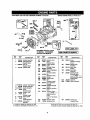
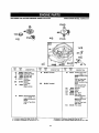
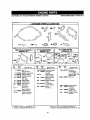
CRAFTSMAN
2400
PSI HIGH PRESSURE
WASHER 919.679180
BRIGGS ENGINE MODEL #12F802-2017
287
684t
615e
404_
177
616
525
10810
307 8 306
6356
REF.
NO.
PART
NO,
1
2
493260
399269
3
5
*299819
691160
13_
DESCRIPTION
REQUIRES SPECIAL TOOLS
TO INSTALL SEE REPAIR
INSTRUCTION MANUAL
REF.
NO.
Cylinder Assembly
Bushing/Seal Wut
(Magneto Side)
Seal-Oil
(Magneto Side)
Cylinder Head
690783
94511
306
307
224324
690345
337
383
404
523
525
562
584
*
•
11
13
231685
94547
51
54
,272199
94526
177
*280393
Cylinder Head Gasket
Breather Assembly
Gasket-Breather
Screw
(Breather Assy)
Breather Tube
Screw
(Cylinder Head)
Intake Gasket
Screw
(fntake Manifold)
O*RingSeal
(Dipstick)
PART
NO.
227
287
505
7*5272916
8
495786
9 _272481
10
94955
9_
585
615
615
625
635
DESCRIPTION
Governor Lever
Screw
(Dipstick Tube)
Shield-cylinder
Screw
11019
LABELKWl
I10ssOWNER'S
MANUAL
REF.
NO.
684
PART
NO.
I
DESCRIPTION
690345
Screw
847
495263
(cylinder Shield)
BO25g_ Sperkplug
89838 Wrench-Bparkplug
690272 Washer
86g
691155
(Breather Passage
Cover)
DipstickJTube
Assembly
Seat-Valve
970
690380
(Governor Crank)
Nut
(Gevemer Lever)
495264 Dipstick
495265 Dipstick Tube
94852 Bolt
(Govemor Lever)
692342 Cover-Breather
Passage
*272238 Breather Passage
Gasket
94474 Retainer-Governor
Shaft
263175 Governor Crank
Note
263202 Govemor
Crank
871
262001
1010
1058
494256
273693
1081
*280966
2310_2
Used on Type No(s).
3116.
497465 Manifold-Intake
66538 Sparkplug Boot
Included in Gasket Set-See Ref. No. 358.
included in Carburetor Kit-See Ref. No. 121.
(Intake)
Seat-Valve
(Exhaust)
Bushing-Guide
(Exhaust Valve)
Note
63709 Bushing-Guide
(intake Valve)
Label Kit
Owner's Manual
O-Ring Seal
(Dipstick Tube)
• ' Included in Carburetor Gasket Set-See Ref. 977.
O Included in Valve Overhaul Gasket Set-See Ref. No. 1095.
19
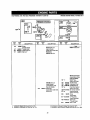
CRAFTSMAN
2400
pSI HIGH pRESSURE WASHER 919.679t80
BRIGGS ENGINE MODEL 912F802-2017
27 O
REF.
NO.
25
PART
NO.
499429
DESCRIPTION
REF.
NO.
PARt"
NO.
26
499425
Piston Assembly
27
263190
DESCRIPTION
Ring Set
(Standard}
Piston Pin Lock
(Used After Code Date
97011200).
*
•
REF.
NO.
28
pART
NO.
499423
DESCRIPTION
Piston Pin
(Standard)
29
499424
32
94699
33
34
262651
262652
35
691270
36
691270
40
93312
45
262204
Connecting Rod
(Standard)
Screw
(Connecting Rod)
Exhaust Valve
Intake Valve
Valve Spring
(Intake)
Valve Spring
(Exhaust)
Valve Retainer
Vatve Tappet
• Included in Carburetor Gasket Set-See Ref. 977.
O Included in Valve Overhaul Gasket Set-See Ref. No. 1095.
Included in Gasket Set-See Ref. No. 358.
Included in Carburetor Kit-See Ref. No. 121.
2O
CRAFTSMAN
2400
PSI HIGH PRESSURE
WASHER 919.679180
BRIGGS ENGINE MODEL # 12F802-2017
24
;-II I
NO.
lS
I'AIII
NO.
D L::$,r.:m.-"i
'O "--
tiFF
I'_€,)
PAnT
N(_
I]' _;4:1111'
II[)N
RF.F.
NI)
PART
N_I
I_ ._;(;I III'LII)N
691461 Cmnle;h_.ft
24.
1411
3_;7A
741
Inoluded
Inra_r.,ket.,..:.et
_e,_.14,_N_ _,0
h,4:k_|wd
i. ¢.:_.ibur,.l,_._
KiI. :Br..:e
p,,:f..NlO,121.
222Q91) I Iy_tlOOl
K_
_4.'111 Ilrl_JOKM _,
94_,',?.9K,cy Drive. Pulley
_R]_.'IRh [;_t- hmlrv_
Irlr:hllJi4tJ i|1( ;+rl _.+PI,_I<
I' (;I_HkHI I:;_4t-_;€.11.1
1 (#_. _,"/,
_:._.neluaed In Vb.f_e O_..'(:_haul Qa,.<et Set _;c.:" Ref No
21
1 _.
CRAFTSMAN
2400
PSI HIGH PRESSURE
WASHER 919.679180
BRIGGS ENGINE MODEL #12F802-2017
374_
46A
15_
374
715_
101
REF.
NO.
PART
NO.
4A
12
15
15A
20
493365
*272198
94880
94470
*399781
29A
391484
22
94220
DESCRIPTION
REF.
NO.
PART"
NO.
46
691445
Engine Sump
Crankcase Gasket
Oil Dmin Plug
Oil Drain Plug
OII Seal
(PTO Side)
Oil Seal
(PTO Side)
Screw
DESCRIPTION
Camshaft
REF.
NO.
83
PART
NO.
231671
46A
691459
Used on Type No(s).
1170, 2950, 2951,
690527 Auxiliary Ddve
Shaft
Camshaft
101
374
715
721
743
493737
Auxiliary Drive Shaft
Note
690522 Auxiliary Drive
Shaft
(Engine Sump)
43
DESCRIPTION
93474
691074
94929
690449
231279
Governor/Oil Slinger
Note
499246 Governor/Oil
Slinger
Used on Type No(s).
3116,
1102
Included in Gasket Set-See Ref. No. 358.
Included in Carburetor Kit-See Ref. No. 121.
691255
Used on Type No(s).
1141, 1172, 1516.
Shaft Pin
Washer
Screw
Stop-Shaft
Gear-Drive
(Counterclockwise)
Note
690518 Gear-Drive
(Clockwise)
Used on Type No(s).
0860, 2950.
Pilot-Guide
• Included in Carburetor Gasket Set-See Ref. 977.
O Included in Valve Overhaul Gasket Set-See Ref. No. 1095,
22
CRAFTSMAN
2400
PSi HIGH PRESSURE
1=51
WASHER 919.679180
I PRIMER
BRIGGS ENGINE MODEL 1112F802-2017
SYSTEM I
f
124
e7, 1137<
708
1_--_'_-
130 95
_
REF.
NO.
PART
NO.
95
94098
97
104
117
493267
e691242
494870
DESCRIPTION
REF,
NO.
110
_)
617
PART
NO.
Screw
(Throttle Valve)
Throttle Shaft
Float Hinge Pin
Main Jet
_
DESCRIPTION
1100
REF.
NO.
PART
NO.
DESCRIPTION
........
498254
497315 Main Jet
(High Altitude)
(Used After Code Date
96O6O2OO).
496495 Main Jet
Note .....
Carburetor
497314 Carburetor
130
691203
133
396187
134 e398188
137 •_
(Used Before Code
Date 95103000).
Welch Plug
(Sold in Kit Only)
Throttle Valve
Carburetor Float
Needle/Seet Kit
Float Bowl Gasket
163,_e_272653
(Sold in Kit Only)
Air Cleaner Gasket
127
497348 Main Jet
125
498170
(High Altitude)
(Used Before Code
Date 95103000).
Carburetor
(Used After Code Date
96060200).
•
276 e.
365
94525
617 ee270344
708 •_.691321
975
*
•
Included in Gasket Set-See Ref. No. 358.
Included in Carburetor Kit-See Ref. No. 121.
493640
Sealing Washer
(Sold in Kit Only)
Screw
(Carburetor)
O-Ring Seal
(Intake Manifold)
Seal-Dust
(Throttle Shaft)
Bowl- Float
Included in Carburetor Gasket Set-See Ref. 977.
Included in Vah/e Overhaul Gasket Set-See Ref. No. 1095.
23
CRAFTSMAN
2400
BRIGGS ENGINE MODEL # 12F802-2017
PSI HIGH PRESSURE WASHER 919.679180
365%
708A
0
F_-']
12_
0A
95_
Ic. s,s+
REF.
NO,
94
95
97
98
104
108
109
109A
PART
NO.
DESCRIPTION
e493765 Idle Mixture Kit
94096 Screw
(Throttle Valve)
493267 Throttle Shaft
398t 85 Idle Speed Kit
e691242 Float Hinge Pin
223471 Choke Valve
494218 Choke Shaft
498593 Choke Shaft
°'+
REF.
NO.
PART
NO.
125A
498965
DESCRIPTION
Carburetor
FIEF.
NO.
217
498977
DESCRIPTION
262749 Choke Return Spring
Note
890572 Choke Retum
Spring
276 •.
365
117A
PART
NO.
617
Main Jet
127
•
Welch Plug
(Sold in Kit Only)
130A
223470 Threttle Valve
133
398187 Carburetor Float
134 e398188 Needle/Seal K_t
137 h
Float Bowl Gasket
(Sold in Kit Only)
163.o+272653 Air Cleaner Gasket
706
708A
975
4P Included
O Included
Included in Gasket Sot-See Ref. No. 358.
Included in Carburetor Kit-See Ref. No. 121.
24
Sealing Washer
(Sold in Kit Only)
94525 Screw
(Carburetor)
e.270344 O-Ring Seal
(Intake Manifold)
•,691321
Seal-Dust
(Throttle Shaft)
Note
e+691321 Seal-Dust
(Choke Shaft)
e_693867 Seal-Dust
Used on Type No(s).
1910, 2001,2017,
2403. 2404, 2407,
2681, 2682, 3116,
493640 Bowl-Float
in Carburetor
Gasket Set-See
Ref. 977.
in Valve Overhaul Gasket Set-See
RSt. No. 1095
BRIGGS
ENGINE
MODEL
#12F802-2017
CRAFTSMAN
2400PSiHIGH
PRESSURE
WASHER
919,679180
Rcr. PP_T
"J(1.
20g
N¢).
Rcr.
r)l-_C:.:-ll P I I,;)N
0_3'i2eJ2 _ _tirG:i- Governt:r
Irluludad iraC.,_P_L Sel-_e
N()
I
PA_T
N_)
I_F.-_r_,T,
ON
I
' ;AH
No.
No.
or.£.cNlr
2531:144_prm;_ [_av.
n_r, i_,>,_.
• include(:[ In _/bur_or
_ar, ki_t .%_t up._ HRt RT7
r
I,. Irluluded in Valw Owrhaul
Go_k_t
_L-'t _o_ H_. N_',. l,_r_r,.
25
CRAFTSMAN
2400
PSI HIGH PRESSURE
WASHER 919.679180
BRIGGS ENGINE MODEL #12F802-2017
L, , .._':)
t!,,+! ' tl
940 _,,_"
091_9_0 _
`'" ":_'_]*
...."
621 +_
Use With Choke
Type, Cm'bulBto¢
"r"11%%11%
g84
r... '°:'
,0,<f:/
RFF
NO.
1B
9BA
1BO
202
23_
22.2
FART
NO.
HH-.
P',O.
DrscnlPTION
_J1142 _urew
_tl._+
mr_l Cover)
49_,_DI Idle S_uu-Ji._.
94_4Zl+_,_r _(C'u.Lr,,,,I
Bm¢l,,,_O
202.'S'_ Muul,ahi¢_lO0..,I i_ll_
2024_;1 Lut;_u[ Link
497_a3 C._ntr,J{
Br_ke*L
Ul+edwith Pri_er
Type _:otbuml_r
PAH I
NO.
DE,_.CFIIPTIDN
322B
892150
Cu_drol D_ar.:kut
259
347
447
4_1223
69139_
93801
Br_;ket-C_iu_
Clu,u+J
_wituh- R,,_ukvr
_¢€@_
(GOh(rOI'C;.,0v_h
HI-F.
NO.
I_
043
e4_vt
092
_40
(_m.,_5_A_I, Brau'(.ut)
e0_.A
0_I'_._,44 Ct..+V_,r - I_ U rktFj i
In-'tudL'_ m GaSket G_t ._€_- R_f. No. 3:>t_.
hiulu'J-L-_l
iulC_buaul_ _L-Su_ +r'q_r.No. 121.
904
990
PARI
NO.
D:"SCFIIPTION
,4g3023
Spa_,er
Orlulud_= Z_
272618 _lue+,_u- L+_ur
2oo14_ ._l_'..,ve-L.+'.,',+r
6t_06+)_, -._,','i_l" F,,uy
94082 -_ruw
(Ga+riri,j _--l_.r+lp
D,r,u,_i_t)
'6,_2072 Dr,t,t_l,,eL-_p 5wiL+h
3929_2 Key _.!
Includedin _=-bumtor Gu=k_t_et _ee Ref. Lr//.
IL_l==ulud_l
ir=Wive OverhaulGauketS_t-Sue Re[. Hu. t_
26
CRAFTSMAN
2400
BRIGGS ENGINE MODEL 112F802-2017
PSI HIGH PRESSURE WASHER 919.679180
tY I
I
269
z
268
,
270
265 '_"
265A {_'
334 _'
.., ,.. ...S",_...,
""..:'_ ,_-'-,:,....
RFF
i'qO.
R[F,
PART
NC..
270
25_A
L:_B
C_ln_t-r.;orttrol Wnro
(72 _ Lollg, _;Jt to
Hc_iulro,_ L_ngtfl;
.......
Not_ .....
_P_tD72 CaEin 9 ,-3o'_trnl W_m
25_
_
RF.F
NO,
271
33,3
3a4
Nut
{_._antrolWi'_ Cs=irlg)
2_I)_D_ Lev_r-Corlltol
_g,2_74 Armstute-Mul_nuL_
g4731 _;rew
3_6
3_9
9Z'_1 Wu_l]u,
_z3gO Wiru-_tuu
9Obr6 Nut
2215,')5 Ct_q,'r',l."¢;__In'x3
6_1_
PA_T
DESGrt.IPTION
(4_,"long, Cut to
HCqblrod Longt|l_
Wnr_ Control
423
_S' Lang, CuL to
R oquimd Lunngtlh_
--- ....
Not= ....
2ED_9 Wiro Cuntrol
50?
,520
61425
e_37-5_ 5_:_uw
PART
NO.
DESCRIPTION
8Zl
_'_#
8Sl
396047 .'3w;_.lp-_IuF_
_4512 _;ruw
4_.lt_B l_nmnal C,31)l_
91Q
_-_
_3
9451D St.J¢l _tatar Mounkng
2ti2r_O ._3tml_ _raka
t_E_ko,2 EI-_I_
_=ad ._,fterCade D_t=
.=Y_
1U_;[)D).
.......
Note .....
3_t'[_a _wttch
Interlock
:_5_5
h'_$
uI_I=X
6910_I T_,r.i=_l
(AItP.rn,_t_r)
_,_4' L_n_, Cut t_
H c;qtJltad
included in C_k_t
L_n
5ut-_ee
_Ith)
Re_ N_. _S_.
• Irmlu_d nn _rlgur_tor Gasket _L-_ue
_ur, _/t,
Inclbd_d in _alve Overhud O_._ut _,_.-5ee qe" _J,) I0_5
27
CRAFTSMAN
2400
PSI HIGH PRESSURE
WASHER 919,679180
BRIGGS ENGINE MODEL # 12F802-2017
m |
9zlB ..L •
i
_iq.,. "-.. '_'--f ,"._
.,....:.,
t ,°:"
_.:-":':""
- _,_"" ...:::'"I
.:.:,..
,....
../"" ,.......
../."
'-...
.°
..°'"
670''_
i
RFF
NO.
F_.RT
NO.
D _ESCRIPT'ON
RFF
NO.
101 397974 C,._p--uel "_fr k.
tva7 492790 Lir_'-[-uel
2_004
N,_te
Lirlu- f"L,ul
4501
_0|A
P,adTl"
NO.
1(:136EMISSIONS
L_J-_GHIPI ION
93063 Cl_mp Ho;e
(GrReri;,
9,TB0"/ Clar_p I IGm
([:].la=_)
I_E'r_)"
961t
LABEL
PJ_:(T
Nt_
!
nF$_.,nlPTTOI_
04r_6
I-Im:r,I;',O)
•19_E
499141 I-ml_lmn._ I _1_._1
0_3.
m7_t ;,"I_0)
499340 F.:rnl_
_.nn_
190
z4ea
_4,._11 8_'rvw
_rL_ITArlk_
=_KgO I-i ter-r'uel
9.,30
9,._A
• .3_
28113_S GU;r_] R_.v,_nd
090_9B
Gu,lr_ I_nd
69'1_45 (-_u,lrcJ.H_lnd
141_1J
('J_,rJ
In €'_.',IIqf F,m-F,_R I-]qL ND. _SR.
Ir_dudedin Ca'b=retor kC,
Jt-See Ref. No. I_1.
28
1D.50
r3p_lv-_
97_1 ,_t00:*.
3J[_54D $¢¢$w._llt_
r _t
CRAFTSMAN
2400
PSI HIGH PRESSURE WASHER 919.679180
BRIGGS ENGINE MODEL # 12F802-2017
23A
37 I
304
305_
925
REF.
NO.
PART
NO.
23A
492175
DESCRIPTION
REF.
NO.
304
37
73
PART
NO.
493293
DESCRIPTION
REF.
NO.
PART
NO.
DESCRIPTION
Housing-Blower
Flywheel
224511 Guard-Flywheel
691222 Screen-Rotating
305
591108 Screw
332
363
455
925
92284
19069
691219
690595
(Blower Housing)
Nut-Flywheel
Flywheel Puller
Cup-Flywheel
Cover-Linkage
Included in Carburetor Gasket Set-See Ref. 977.
0 IncJudedin Valve Overhaul Gasket Set-See Ref. No. 1095.
Included in Gasket Set-See Ref. No. 358.
• Included in Carburetor Kit-See Ref. No. 121.
29
CRAFTSMAN
2400
PSi HIGH PRESSURE
WASHER 919.679180
BRIGGS ENGINE MODEL #12F802-2017
689 0
L
REF.
NO.
PART
NO.
55
691421
58
280399
59
60
60A
396892
281434
393152
DESCRIPTION
Rewind Starter
Housing
Starter Rope
(Cut To Ri_luired
Length)
Grip Insert
Starter Rope Grip
Starter Rope Grip
REF.
NO.
PART
NO.
65
94904
144
456
459
498144
281503
281505
DESCRIPTION
Screw
(Rewind Starter)
Pulley/Spring Assy
Plate-Pawl Friction
Pawl- Retchet
Included in Gasket Set-See Ref. No. 358.
Included in Carburetor Kit-See Ref, No, 121.
REF.
NO.
PART
NO.
DESCRIPTION
461
94943
592
(Pawi Friction Plate)
949O8 Nut
608
689
946
497680
263073
223294
Screw
(Rewind Starter)
Starter-Rewind
Spring-Friction
Stop-Rope
Included in Carburetor Gasket Set-See Ref. 977.
Included in Valve Overhaul Gasket Set-See Ref. No. 109_
30
CRAFTSMAN
2400
PSI HIGH PRESSURE
BRIGGE ENGINE MODEL #12F802-2017
WASHER 919.679180
68
592 _)
1
689O
456 I_
461
946
L
REF.
NO.
PART
NO.
55
891421
58
280399
59
60
60A
396892
281434
393152
Included
Included
DESCRIPTION
Rewind Starter
Housing
Starter Rope
(Cut To Required
Length)
Grip Insert
Starter Rope Grip
Starter Rope Grip
REF.
NO.
PART
NO,
65
g4904
144
456
459
4_144
281503
281505
DESCRIPTION
Screw
(Rewind Starter)
Pulley/Spring Assy
Plate-Pawl Friction
Pawl- Ratchet
REE
NO.
PART
NO.
461
94943
592
94908
608
689
946
497680
263073
223294
DESCRIPTION
Screw
(Pawl Friction Plate)
Nut
(Rewind Starter)
Starter-Rewind
Spdng-Fdction
Stop-Rope
• Included in Carburetor Gasket Set-See Ref. 977.
O Included in Valve Overhaul Gasket Set-See Ref. NO. 1095
in Gasket Set-See
Ref. No. 358,
in Carburetor
Kit-See Ref. No, 121.
31
CRAFTSMAN
2400
PSI HIGH PRESSURE
WASHER 919.679180
BRIGGS ENGINE
MODEL #12F802-2017
S92
.
..,"
!
/
.p" ,,,._,.
_'-.
•.;-_
--...."
._.
...:.. .i _ _'-7_.
_u t.. t ..
.7,....
•-:-.,-'--_..=. -;_;.,.:
..
,,
PAH I
NO.
r'iF!l .P,RIPTil"lN
_.F.l".
Nl_l
llS
PAINT
N:).
_cr.
r_._t'_,R'llaTION
N_)
PART
N_
_1_89
21K]_99
Hetvlrill '_t;l-lcr ,._pr,_f_
_t_rt_.r -IDI_
r_RIFITION
949(14 HCmW
H_IJ_I_
57A
511
,o"
946 ..q..;,
101
Ht-f',
NO.
•
_'_...:_.._
73_
101
2"P5_
2_4627 _'_n
HDt_tln0
262626 P_ _h_ft
2B09T_ W_._F_r _J
4,_/JiA
439A
224_21 Plam-Pliw" I'rl=llori
492e33 Paw]- F{_l_'l_-i
67B
1t2427B
In_:ludc(l;l:
691219 (_up)-I'#'_lhc_l
_'v_lrl_l _llDcar
3_lll
224322
Guide-Rule
W_U h_,r
(i_ui T_Requi_ed
Lenilith)
1f9
6OA
_
:!1t_1_l
Grip Inll_rl
_lii/t-'_ -"lope Glip
94_A
1_:_4
(_w_ind _l_lr_l)
lil;lud_
ill _,itll_[
,_tl-,.e, le
_ef
NO 35_
_#_IllP.IIJtllI(t In Vi_I_
32
()v_rblllJI
('-iil._kitt F,lli -_;_l_ l-lilt. NI'_I II_R
CRAFTSMAN
2400
PSI HIGH PRESSURE
35BEHG_E
177 .t"
......._
OVERHAULGASKETSET
"_i_"
3 _,_,
..,J,._
1081 _.'$
_... _ ..._
<;,:.,_. :_ /
1095 VALVE OVERHAUL
GASKET SET
HLI.
NO
F',/,.'_T
NC).
3; *QggwI_)
I;I-P;'L:HIP 1 I_N
977 CARBURETOR
GASi_ET SET
r_EF.
NO.
PAFI'r
NO.
_J_E.,_3
RIl>'i'lON
RFF
NO.
PAR1
NO.
12
_Q'i_lg_
{:rankca-_=G_-k_t
@:alggTgl
_u_l-Oil
61
+_rZ199 intakeC1,u_t
_4
e4_3?E5
Idle M_xtur_ Kit
1D4
12t
_g1242
4_I_gEG
rlt_Lltiii_Pir_
E_mur_t_r
12_
iv
W_l(':l'_ =hJQ
!7,0(Lle
1"/7 ^_103_
C%RIhQt-1_ll
(Di_ti_
275 _@
R_llncj W_hm
(_:ld m I_t Only_
358
40731G Fngrr _ _,_'h_ul
Gasket _et
_e)
20
565
^272238
Rt_,_er
G=ket
(Goad rl Kit O.Iy')
g77
49_.G1
1_81
*2B0gEG
t a£6
4g_:,,2_
134 _,,_gOl_8 N_udl,.,_Se,_
I<_"
(_uld .n KitO.Iy_
in C_tLmrulur
Ki_-._ee
SF,={t)
Pp_g_
817 • 412704J44 0 - R;I_,_I
_1
,_lnt=kaM_nifo_
$80 ,493623 SIJ_uur
/In €llJClP.¢
2)
O_=.rh_ulKi_
In_lud_J
DC_Ci-[IPTION
1_3*_'IFZT"_S3 Air _:le_J_ur_kuL
_D=J 'r.3;l
(Muuneto
BRIGGS ENGINE MODEL # 12F802-2017
WASHER 919.679180
(_a:,k_L't _t
CarbLs_tor
U HIn¢] _nt
t,UIp=tlak hlbP.)
t.;;ar._,t F,(_t V,11_
t.)vP.rh,ll JI
,(i ]llUll.lLtUd in CdlbU'U'.Ui _,,_€_lte_..°,e_.-.._ecJRef g77
h.oluLl*)(I in V_lve Overl'_ll
qm_t
Ht_t-H_R R_t. Nn. 10_
R_r NO _21
33
Bdggs
&Stratton
Corporation
(B&S),
theCalifornia
AirResources
Board
(CARB)
andtheUnited
States
Environmental
Protection
Agency
(U.S.
EPA)
Emission
Control
System
Warranty
Statement
(Owner's
Defect
Warranty
Rights
andObligations)
Intheintarast
of theenvironment,B&Seegines thatmeet stricternis-
TO CERTIFIED ENGINES PURCHASED IN CALIFORNIAIN 1995
sionrequirernentsarelabeled,"Thlaenginasontormeto
1995-1998
AND THEREAFTER, WHICH ARE USED IN CALIFORNIA, AND
Califomia emissionregulationsfor ULGE enginesand U.S. EPA
TO CERTIFIED MODEL YEAR 1997 AND LATER ENGINES
Phese I regulstionsfor smallnon-roedengines."
WHICH ARE PURCHASED AND USED ELSEWHERE IN THE
EMISSION CONTROL WARRANTYCOVERAGE IS APPLICABLE
UNITED STATES.
Callfomla and United States Emission Control Defects Warranty Statement
CARB, U.S. EPA and B&S are pleased to explain the Emission
there has been no abuse,neglector impropermaintenanceofyour
ControlSystemWarrantyon your1996 andlat_" utilityor lawnand
ULGEengine.
gardenequipment(ULGE)engine. InCalifomia,newULGEengines
Youremissioncontrolsystamincludespartssuchas the carburetor,
producedon or after August 1, 1995 must be designed,built and
air cleaner,ignitionsystem, muffler end catalyticconverter.Also
equippedto meet the State'sstringentanti-smogstendards_Elseincludedmaybeconnectorsandotheremissionrelatedassemblies.
where in the United States, new non-road,spark-ignitionengines
Where a warrantablecondition exists, B&S will repairyour ULGE
certifiedfor modelyear 1997and later,mustmeet similarstandards
engine at nooust to youincludingdiagnosis,partsand labor.
setforthby the U.S. EPA. B&S must warrantthe emissioncontrol
systemonyourengineforthe pe_s of time listed below,provided
Bdggs & Stratton Emission Control Defects Warranty Coverage
ULGE engines are warranted relative to emissioncontrol parts
bstow.lfanycoveredpartonyourenginaisdefective,thepartwillbe
defectsfor a periodof two years, subjectto provisionsset forth
repairedor replacedby B&S.
Owner's Warranty Reel:X)nelbilttlas
Asthe ULGEengineowner,youare responsiblefor the performance
Youare responsibleforpresentingyourULGE engineto an Authoofthe requiredmaintenancelisted in yourOperatar/OwnerManual.
rizedB&S ServiceDeeler as soonas a problemexists.The undisB&S recommendsthat youretainallyourreceiptscoveringmainta.
pu:tsdwarrantyrepairsshouldbe completedina reasonableamount
nanceon yourULGE engine,but B&Scannotdenywarrantysolely
oftime, notto exceed 30 days,
forthe lackofreceiptsorfor yourfailuretoensurethe performanceof
if you have any questions regarding your warranty rightsand
all scheduledmaintenance.
responsibilities,
you shouldcontacta B&S ServiceRepresentative
at 1-414-259-5262.
Asthe ULGEengine owner,youshouldhoweverbeawarethat B&S
may deny youwarrantycoverageifyourULGEengineor a part has
The emissionwarrantyis a defectswarranty.Defectsarejudgedon
faileddueto abuse, neglect,impropermaintenance or unapproved
normalenginepedormanos.The warrantyisnot relatedtoan in-use
modifications.
emissiontest.
Brlggs & Stratton Emission Control Defects Warranty Provisions
Thefollowingare specificprovisionsrelativeto yourEmissionControlDefectsWarrantyCoverage.It is in additiontothe B&S enginewarranty
for non-regulatedenginesfound in the Operatar/OwnerManual.
1. WarrantedParts
3. No Charge
Repairor replacementof any WarrantedPartwill be performed
Coverage underthis warrantyextendsonly to the partslisted
at nocharge to the owner,including diagnostic labor which laeds
below (theemissioncontrolsystemsparts) to the extentthese
to the determination that a Warranted Part is defective, if the
partswere presentonthe enginepurchased.
diagnostic work is performed at an AuthorizedB&S Service
a. FuelMeteringSystem
Dealer. For emissionswarrantyservicecontactyour nearest
•
Cold startendchmentsystem(softchoke)
Authorized B&S Service Dealer as listed in the "YellowPages"
•
Carburetorandinternalparts
under =Engines, Gasoline," "Gasoline Engines," "Lawn
Mowers," or similarcategory.
•
FuelPump
4. Claims and Coverage Exclusions
b. Air InductionSystem
Warranty claimsshallbe filed in accordancewiththe previsions
•
Air cleaner
ofthe B&S EngineWarranty Policy.Warrantycoverage shallbe
•
Intake manifold
excluded for failures of Warranted Parts whichare not original
B&S parts or because of abuse, neglector improper maintec. IgnitionSystem
nenos as setforth Inthe B&S Engine WarrantyPolicy.B&S is not
• Spark plug(s)
liable to coverfailuros of Warranted Parts caused by the use of
•
Magnetoignitionsystem
add-on, non..odginal,or modified parts.
5. Maintenance
d. Catalyst System
Any Warranted Part which is not scheduledfor replacement as
Catalyticconverter
required maintenance or which is scheduledonly for regular
•
Exhaustmanifold
inspection to the effectof =repair or replace as necessary" shall
•
Air injectionsystemor pulsevalve
be warranted as to defects for the warranty period. Any
Warranted Part whichis scheduledfor replacement as required
e. MiscellaneousItems Used in AboveSystems
maintenance shall be warrantedas to defectsonly for the period
•
Vacuum,temperature,position,timesensitivevalves
of time up to the first scheduledreplacement for that part. Any
and switches
replacementpart that is equivalentinperformance and durability
•
Connectors and assemblies
may be used inthe performance of any maintenance or repairs.
2. Lengthof Coverage
The owner is responsible for the performanceof all required
maintenance, as defined in the B&S Operator/Owner Manual.
B&Swarrantstotheinitialownerandeachsubsequentpurchaser
thatthe WarrantedPartsshallbe free from defectsin materials
6. Consequential Coverage
and workmanshipwhich caused the failure of the Warranted
Coverage hereunder shall extend to the failure of any engine
Partsfor a pariud oftwo yearsfrom the datethe engine is delivcomponentscaused by the failure of any Warranted Part still
ered to a retailpumhaser.
under warranty.
34
Bdggs & Stratton welcomes warranty repair and apologizes
to you for being inconvenienced. Any Authorized Service
Dealer may perform warranty repairs. Most warranty repairs
are handled routinely, but sometimes requests for warranty
service may not be appropriate. For example, warranty would
not apply if engine damage occurred because of misuse, lack
of routine maintenance, shipping, handling, warehousing or
improper installation. Similarly, warranty Is void if the serial
number of the engine has been removed or the engine has
been altered or modified.
4.
5.
Repair or adjustment of associated parts or assemblies
such as clutches, transmissions, remote controls, etc.,
which are not manufactured by Briggs & Stratton.
6. Damage or wear to parts caused by dirt, which entered
the engine because of improper air cleaner maintenance,
re-assembly, or use of a non-original air cleaner element
or cadddge. (At recommended intervals, clean and re-oil
the Oil-Foam® element or the foam pre-cleaner, and
replace the cartridge.) Read "Owner's Manual."
7. Parts damaged by overspeeding, or overheating caused
by grass, debris, or dirt, which plugs or clogs the cooling
fins, or flywheel area, or damage caused by operating the
engine in a confined area without sufficient ventilation.
(Clean fins on the cylinder, cylinder head and flywheel at
recommended intervals.) Read "Owner's Manual."
8. Engine or equipment pads breken by excessive vibration
caused by a loose engine mounting, loose cotter blades,
unbalanced blades or loose or unbalanced impellers,
improper attachment of equipment to engine crankshaft,
overspeeding or other abuse in operation.
9. A bent or broken crankshaft, caused by stdking a solid
object with the cutter blade of a rotary lawn mower, or
excessive v-bait tightness.
10. Routine tune-up or adjustment of the engine.
11. Engine or engine component failure, i.e., combustion
chamber, valves, valve seats, valve guides, or bumed
starter motor windings, caused by the use of alternate
fuels such as, liquified petroleum, natural gas, altered
gasolines, etc.
If a customer differswith the decisionof the Service,Dealer, an
investigation will be made to determine whether the warranty
applies. Ask the Service Dealer to submitall supportingfacts to
his Distributor or the Factory for review. If the Distributoror the
Factory decides that the claim isjustified, the customer will be
fully reimbursed for those items that are defective. To avoid
misunderstanding which might occur between the customer
and the Dealer, listed below are some of the causes of engine
failure that the warranty does not cover.
Improper maintenance:
The life of an engine depends upon the conditions under
which it operates, and the care it receives. Some applications,
such as tillers, pumps and rotary mowers, are very often used
in dusty or dirty conditions, which can cause what appears to
be premature wear. Such wear, when caused by dirt, dust,
spark plug cleaning grit, or other abrasive material that has
entered the engine because of improper maintenance, is not
covered by warranty.
This warranty covers engine related defective material
and/or workmanship only. and not replacement or refund
of the equipment to which the engine may be mounted.
Nor does the warranty extend to repairs required
because of:
1. PROBLEMS CAUSED BY PARTS THAT ARE NOT
ORIGINAL BRIGGS & STRA'I-rON PARTS.
2.
Equipment controls or installations that prevent starting,
cause unsatisfactory engine performance, or shorten
engine life. (Contact equipment manufacturer.)
3.
Leaking carburetors, clogged fuel pipes, sticking valves,
or other damage, caused by usingcontaminated or stale
fuel. (Use clean, fresh, lead-free gasoline and Briggs &
Stratton gasoline stabilizer, Part No. 5041 .)
Pads which are scored or broken because an engine was
operated with insufficient or contaminated lubricating oil,
or an incorrect grade of lebdceting oil (check oil level daily
or after every 8 hours of operation. Refill when necessary
and change at recommended intervals.) Read "Owner's
Manual."
35
_ARS
OWNER'S MANUAL
CRAFTSMAN
The model number of your Sears Air Compressor
found
can be
on the maintenance label on the top of the shroud or on the
bar code label on the rear of the air tank.
MODEL NO.
919.679180
SERVICE AND REPAIR PARTS
CALL
1-800-665-4455"
Keep this number handy should you require a service
SERVICE
call or need to order repair parts.
If ordering parts make sure you have the name, make
and model no. of the merchandise
and the name and
number
of the part you wish to order.
*If calling locally, please use one of the following numbers:
Regina -566-5124
Toronto-744-4900
Kitchener-894-7590
Vancouver
Montreal-333-5740
Halifax -454-2444
Ottawa-738-4440
- 420-8211
WHEN ORDERING REPAIR PARTS, ALWAYS
FOLLOWING
INFORMATION:
HOW TO ORDER
REPAIR PARTS
GIVE THE
• PART NUMBER
•
PART DESCRIPTION
• MODEL NUMBER
• NAME OF ITEM
All parts listed may be ordered from any Sears Service Center
and most Sears stores.
If the parts you need are not stocked locally, your order will be
electronically transmitted to a Sears Repair Parts Distribution
Center for handling.
Sold
By Sears
Canada,
Inc.,
Toronto,
Ont.
M5B
2B8