1
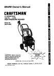
Operators Manual
2 GPM
HIGH PRESSURE WASHER
Model No, 580.768110
HOURS: Mon. - Fri. 8 a.m. to 5 p.m. (CT)
CAUTION:
Before using this product, read this
manual and follow all its Safety Rules
and Operating Instructions.
Sears, Roebuck
and Co., Hoffman
Estates, IL 60179
Visit our Craftsman website: www.sears.€om/craftsman
Part No. B3774 Draft 1 (4/19/1999) printed in f_e U.S.A.
•
•
•
•
•
Safety
Assembly
Operation
Maintenance
Parts
Safety Instructions
...................
2-3
Assembly ............................
4
Operation ..........................
Maintenance
......................
LIMITED
Storage.
Troubleshooting
5-8
9-12
ONE YEAR WARRANTY
...........................
Replacements
......................
Parts
Order Parts / Request
ON CRAFTSMAN
13
14
................
16-27
Service .....
HIGH PRESSURE
Back Page
WASHER
For one year from the date of purchase, when this Craftsman Cleaning System is maintained and operated
according to the instructions in the owner's manual, Sears will repair, free of charge, any defect in material and
workmanship.
If this washer is used for commercial purposes, this warranty applies.for only 90 days from the date of
purchase. If this high pressure washer is used for rental purposes, this warranty applies for only 30 days after
date of purchase.
This warranty does not cover:.
• Expendable items such as spark plugs or air filters, which become worn dudng normal use.
• Repairs necessary because of operator abuse or negligence, including damage resultingfrom no water
being supplied to pump or failure to maintain the equipment according to the instructionscontained in the
owner's manual.
WARRANTY SERVICE IS AVAILABLE BY RETURNING THE HIGH PRESSURE WASHER TO THE
NEAREST SEARS SERVICE CENTER OR DEALER IN THE UNITED STATES.
This warranty gives you specific legal rights and you may also have other dghts, which vary from state to state.
Sears, Roebuck
,_
and Co., Dept. 817WA,
CAUTION:
using
this Rules
product,
manual andBefore
follow all
Safety
andread this
Operating Instructions.
A
DANGER: When transporting, setting up,
adjusting or making repairs to your pressure
washer, always disconnect the spark plug wire
and place it where it cannot contact the spark
plug to prevent accidental starting.
Engine exhaust gases contain DEADLY carbon
monoxide gas. This dangerous gas, if breathed in
sufficient concentrations, can cause
unconsciousness or even death. Operate this
equipment only in the open air where adequate
ventilation is available.
2
Hoffman
Estates, IL 60179
•
Gasoline is highly FLAMMABLE and its vapors are
EXPLOSIVE. Do not permit smoking, open flames,
sparks or heat in the vicinity while handling
gasoline. Avoi_ spilling gasoline on a hot engine.
Allow unit to dool for 2 minutes before refueling.
Comply with all laws regulating storage and
handling of gasoline.
•
Locate this pressure washer in areas away from
combustible materials, combustible fumes or dust.
•
The high pressure equipment is designed to be
used with Sears authorized parts only. If you usa
tliis equipment with parts that do not comply with
minimum specifications, the user assumes all dsks
and liabilities.
•
Some chemicals or detergents may be harmful if
inhaled or ingested, causing severe nausea,
fainting or poisoning. The harmful elements may
cause property damage or severe injury.
•
Do not allow CHILDREN to operate the Pressure
Washer at any time.
•
Operate engine only at govemecl speed. Running
the engine at excessive speeds increases the
hazard of personal injury. Do not tamper with parts
which may increase or decrease the governed
speed.
• Do not wear loose clothing, jewelry or anything
that may be caught in the starter or other rotating
•
parts.
•
Before starting the pressure Washer in cold
weather, check all pads of the equipment and be
sure ice has not formed there.
• Units with broken or missing pads, or without
protective housing or covers should NEVER be
operated.
The muffler and air cleaner must be installed and
in good condition before operating the Pressure
Washer. These components act as spark arrestors
if the engine backfires.
Check the fuel system for leaks or signs of
deterioration such as chafed or spongy hose,
loose or missing clamps or damaged tank or cap.
Correct all defects before operating the Pressure
Washer.
•
High pressure spray may damage fragile items
including glass. Do not point spray gun at glass
when in the jet spray mode.
•
Keep the hose connected to machine or the spray
gun while the system is pressurized.
Disconnecting the hose while the unit is
pressurized is dangerous.
•
Hold the spray gun firmly in your hand before you
start the unit. Failure to do so could resuR in an
injuryfrom a whipping spray gun. Do not leave the
spray gun unattended while the machine is
running.
•
The cleaning area should have adequate slopes
and drainage to reduce the possibilityof a fall due
to slippery surfaces.
Keep water spray away from electdc wiring or fatal
electric shock may result..
/-_ Do not spray flammable liquids.
• Never allow any part of the body to come in
contact with the fluid stream. DO NOT come in
contact with a fluid stream created by a leak in the
high pressure hose.
•
Never use a spray gun which does not have a
trigger lock or trigger guard in place and in
working order.
Use a'respirator or mask whenever there is a
chance that vapors may be inhaled. Read all
instructionswith the mask so you are certain the
mask will provide the necessary protection against
inhaling harmful vapors.
Do not secure trigger gun in the pull-bask (open)
position.
Do not by-pass any safety device on this machine.
High pressure streams of fluid this equipment
produces can pierce skin and its underlying
tissues, leading to serious injury and possible
amputation.
The muffler and engine heat up dudng operation
and remain hot immediately after shutting R down.
Avoid contact with a hot muffler or engine or you
could be severely burned.
Never aim the gun at people, animals or plants.
Operate and store this unit on a stable surface.
•
High pressure spray can cause paint chips or
other particles to become airborne and fly at high
speeds.
•
Always wear eye protection when you use this
equipment or when you are in the vicinity where
the equipment is in use.
•
Operate the pressure at no more than the PSI fluid
pressure rated for your pressure washer.
•
Never move the machine by pulling on the high
pressure hose. Use the handle provided on the
top of the unit.
High pressure hose can develop leaks from wear,
kinking, abuse, etc. Water spraying from a leak is
capable of injecting material into skin. Inspect
hose each time before using R. Check all hoses for
cuts, leaks, abrasions or bulging of cover, or
damage or movement of couplings. If any of these
conditions exist, replace hose immediately. Never
repair high pressure hose. Replace R with another
hose that meets minimum pressure rating of your
pressure washer.
•
Always be certain the spray gun, nozzles and
accessories are correctly attached.
I A
MEANS "ATTENTION!!!
BECOME ALERT!!! YOUR SAFETY IS INVOLVED."
LOOK FOR THIS SYMBOL TO POINT OUT IMPORTANT SAFETY PRECAUTIONS.
3
IT
CARTON
CONTENTS
The following parts are shipped loose with your
pressure washer:.
• Main Unit -- pressure washer with wheels, guide
handle.
•
•
High Pressure Hose
Parts Box (which includes items listed below)
Spray Gun
• Wand Extension with Hi/Lo Adjustable Nozzle.
• Engine Oil
• Manual Bag (which includes the Items listed
below)
• Owner's Manual
• Nozzle Cleaner Kit
• =O'-Ring Kit
Become familiar with each piece before assembling
the pressure washer. Check all contents against the
illustration on Page 5. If any parts are missing or
damaged, call the Pressure Washer Helpline at
1-800-222-3136.
TO REMOVE
CARTON
•
•
•
PRESSURE
WASHER
HOW TQ SET UP YOUR PRESSURE
WASHER
For the most part, your Craftsman High Pressure
Washer has been assembled at the factory. You must,
however, assemble the spray gun, and attach the high
pressure hose to the pump and spray gun.
•
Cut the tie wraps on the high pressure hose and
connect high pressure hose to gun. Tighten by hand.
•
Remove plastic cap and connect high pressure
hose to pump. Tighten by hand.
FROM
Remove loose parts and parts box included with
pressure washer.
Slice two comers at guide handle end of carton
from top to bottom so the panel can be folded
down flat.
Remove plastic
cap and attach
high pressure
hose here
Raise guide handle, secure in place and rollthe
pressure washer out the open end of the carton.
• " Attach nozzle extension to spray gun.
Uft the handle to
upright position and
slide the locking
caps into place
•
Check carton for additional loose pads.
•
Place assembled spray gun on holder.
KNOW
YOUR
HIGH
PRESSURE
WASHER
Read this owner's manual and safety rules before operating your h|gh pressure washer.
Compare this illustrationwith your high pressure washer to familiarize yourseff with the locations of various
controls and adjustments. Save this manual for future reference.
High Pressure Hose
Spray Gun
Detergent Pick_Up
Tube and Filter
Recoil Starter
Gas Cap
Throttle Control Lever
Oil Fill Cap
Air Filter
High Pressure Outlet
Adjustable
Nozzle
Water Inlet
Pump
J
Adjustable Nozzle - Adjust for high or low pressure;
narrow or fan spray.
Oil Fill Cap - Fill engine with oil here. See page 7 for
oil recommendations,
Air Filter - Dry type filter element limits the amount of
dirt and dust that gets in the engine.
Pump - Develops high water pressure.
Recoil Starter - Used for starting the engine
manually.
Detergent Pick-Up Tube and Filter - Use to suck
detergent from chemical bottle to the low pressure
water stream.
Spray Gun - Controls the application of water onto
cleaning surface with trigger device. Includes safety
latch.
Gas Cap - Fill gas tank with regular unleaded
gasoline here.
Throttle Control Lever - Sets engine in starting
mode for recoil starter and stops running engine.
High Pressure Hose - Connect one end to the spray
gun and other end to the high pressure outlet.
Water Inlet - Connection for garden hose.
High Pressure Outlet - Connection for high pressure
hose.
5
HOW TO USE YOUR
PRESSURE
WASHER
Cleaning W'dh The Adjustable Nozzle
Read these instructionsand leam how to use your
pressure washer before you attempt to start your
pressure washer. If you have any problems
operating your pressure washer, please call the
pressure washer helpline at 1-800-222-3136.
IMPORTANT: Use soaps designed specificallyfor
pressure washers. Household detergents could
damage the pump.
IMPORTANT: You must attach all hoses before you
start the engine. Starting the engine without all the
hoses connected and without the water turned ON will
damage the pump.
How To Use the Adjustable Nozzle
,_
•
To apply detergent follow these steps:
spraying. Never
WARNING:
Never
putadjust
handsspray
in front
pattern
of thewhen
nozzle
when adjusting the spray.
Push the nozzle forward for low pressure. Pull the
nozzle backward to achieve high pressure.
•
Prepare the detergent solution as required by the
job.
•
Hang the detergent solution on the hook on the
handle.
Hang detergent
bottle on this
hook.
Pull nozzle
backward for high
pressure.
•
Push nozzle forward
for low pressure.
Twisting the nozzle adjusts the spray pattern from a
narrow to a "fan" pattern.
•
Place small filter on the clear, chemical injection
tube into the detergent container.
•
Push the adjustable nozzle forward to low pressure
mode. Detergent cannot be applied with nozzle
in high pressure position.
•
Review the use of the adjustable nozzle.
•
Connect garden hose to water inlet (see =TO
START PRESSURE WASHER" on page 8), check
that high pressure hose is connected to spray gun
and pump (see"ASSEMBLY on page 4), and start
engine.
Note: The first cleaning step is applying an
appropriate cleaning solution to penetrate and loosen
gdme. Apply at low pressure. Leave the solution on
surface for 3 to 5 minutes to allow solution to work.
Reapply as needed to prevent surface from drying.
Note." The second step is cleaning the surface you
have prepared with the pressure washer and then
dnsing it clean.
Twist nozzle
clockwise for
narrow spray.
•
Twist nozzle
counterclockwise for
"fan" pattern.
•
For most effective cleaning, keep spray nozzle
between 8 to 24 inches away from cleaning
surface.
•
If you get the spray nozzle too close, especially
using high pressure mode, you may damage the
surface being cleaned.
For cleaning, start at lower portion of area to be
washed and work upward, using long, even
overlapping strokes.
Allow the detergent to soak in between 3-5 minutes
before washing and rinsing. Reapply as needed to
prevent surface from drying.
6
Rinsing W'dh the Pressure Washer
&WARNING:
use the pressure
Be extremely
washer from
careful
a ladder,
if you must
scaffolding or any other relatively unstable
location. When you press the trigger, the recoil
from the initial spray could force you to fall, or if
you are too close to the cleaning surface, high
pressure could force you off a climbing
appamtus.
•
Hook up the water supply and start your pressure
washer (see TO START YOUR PRESSURE
WASHER on page 8).
•
Pull adjustable nozzle backward for high pressure
mode. Wait for detergent to clear. Detergent will not
flow when in the high pressure mode.
•
When detergent has cleared, you may want to
expand the spray pattern for a more gentle rinsing
action. Start at top of area to be rinsed, working
down with same action as for cleaning.
,_
be cleaned. Test
CAUTION:
Make
a sure
smallthere
area is
of no
thedamage
surface to
caused by the high pressure spray.
BEFORE
STARTING
Although multi-viscosity oils (5W30, 10W30, etc.)
improve starting in cold weather, these muifi-viscosity
oils will result in increased oil consumption when used
above 32°F, Check your engine oil level more
frequently to avoid possible damage from runninglow
on oil.
Place pressure washer on a level surface
•
Clean area around oil fill and remove oil dipstick.
Wipe dipstick clean.
Pour oil from enclosed bottle into the oil fill opening
until oil reaches full mark on the dipstick. Stop and
check the oil level periodically. Do not overfill.
Install oil dipstick, hand tighten securely.
Add Gasoline
•
,_
fuel
DANGER:
tank when
Never
engine
fill fuel
is running
tank indoors.
or hot.Never
Do not
fill
smoke when filling fuel tank.
,i_
CAUTION:
leave
room for
Do expansion.
not overfill the fuel tank. Always
THE PRESSURE
WASHER
• ,_
_obe_etbe_giceyou_llneed_the_lowi_:
Add Engine Oil
Only use high quality detergent oil rated with API
service classification SF or SG. Select the oil's SAE
viscosity grade according to your expected operating
temperature:
colder _
32°F _
warmer
5W30
Use regular unleaded gasoline with the pressure
washer e.ngine. Fuel tank capacity is 1.5 U.S. quart.
SAE 30
CAUTION:
Experience
indicates
that alcohol
blended fuels
(called gasohol
or using
ethanol
or methanol) can attract moisture which leads to
separation and formation of acids during
storage. Acidic gas can damage the fuel system
of an engine while in storage.
To add fuel to engine:
•
Clean area around fuel cap, remove cap.
•
Add regular unleaded gasoline, slowly, to the fuel
tank.
Important: Never mix oil with gasoline.
•
7
Install fuel cap e.nd wipe up any spilled gasoline.
TO START YOUR PRESSURE
•
•
•
•
•
WASHER
Note: For a recently run engine, be sure the throttle
control is in the =Fast" position and the choke is in the
=Run" position.
Place the pressure washer in an area close enough
to an outside water source that can flow at a rate of
at least 2 gallons per minute. Connect a garden
hose to the water spout.
•
Check that the high pressure hose is tightly
connected to the spray gun and to the pump. See
ASSEMBLY section on page 4 for illustrations.
Check inlet screen on the water inlet. If the screen
is dirty, clean before attaching a garden hose. If the
screen is damaged, do not connect to the garden
hose. Replace with screen provided in maintenance
kit or call 1-800-366-PART to order a replacement
inlet screen.
Note: Always keep the Throttle Control Lever in the
'Fast' position when operating the pressure washer.
•
HOW TO STOP YOUR PRESSURE
WASHER
supply
ARNING!
connected
Do not
and
runturned
pumpon.
without
You the
must
water
follow this warning or the pump will be
damaged.
•
Remove the adjustable nozzle extension from the
spray gun.
•
Pull the trigger on the spray gun and hold until a
steady stream of water appears.
•
Engage the safety latch on the spray gun.
•
•
Attach adjustable nozzle extension onto spray gun.
Move the throttle control lever to the "Fast"
position.
•
Move the Run/Stop Lever to the 'Stop' position.
•
Simply shutting off the engine will not release
pressure in the system. Squeeze tdgger on the
spray gun to relieve pressure in the hose.
Note: A small amount of water will squid out when
you release the pressure.
• SIPHONING
We recommend that you DO NOT siphon standing
water for your water supply. Contaminated, brackish or
dirty water can damage the pump. Connect only to
household water supply.
\
TIPS
Fast
Slow
•
When the engine starts, gradually move the Choke
Lever from one position to the next until it is in the
"Run" position.
Note: If'after 3 pulls the engine fails to start, move the
Choke Lever to the 'Run' position, pull trigger on gun
to relieve pressure, reengage safety latch, and pull the
recoil starter handle rapidly (Max. 3 pulls).
Attach the the garden hose to the water inlet.
Turn on the water.
A
Grasp rope handle and pull slowly until you feel
some resistance. Then pull cord rapidly to
overcome compression, prevent kickback and start
the engine. Let rope return to starter slowly,
Set the choke lever to "Choke"
position.
Choke Position /
8
•
Never use the garden hose inlet to siphon
detergent or wax.
•
If you have the spray nozzle tee far away, the
cleaning will not be as effective.
CUSTOMER
RESPONSIBILITIES
HOURLY OPERATING
INTERVAL
MAINTENANCE SCHEDULE
RLL IN DATES AS YOU COMPLETE
REGULAR SERVICE
Eveiy 25
Hours or
Before Each
MAINTENANCE TASK
PRESSURE
Use
SERVICE DATES
Every 100
Hours or
Yearly
Yearly
WASHER
Check/clean water inlet screen
on quick-connect.
Xt
Check high pressure hose,
X
Check detergent hose.
X
Check spray gun and assembly for leaks.
X
Purge pump of air and contaminants.
X
ENGINE
Check oil level.
X
Change engine oil.
X*
Service air cleaner.
X_
Clean/replace spark plug.
X
Prepare for storage.
Prepare unit for storage if it is to
remain idle for longer than 30 days.
Clean if clogged. Replace if perforated or tom.
• Change oil after the first (2) operating hours and every 25 hours thereafter. Change sooner when operating under dirty or dusty conditions.
_' Replace more often under dirty or dusty conditions.
PRODUCT
Pressure
In the State of California a spark arrestor is required
by law (Section 4442 of the California Public
Resources Code). Other states may have similar laws.
Federal laws apply on federal lands.
SPECIFICATIONS
Washer
PRESSURE
Specifications
...................................
FLOW RATE ........................................
DETERGENT
MIX....Use
1900 psi
2 GPM
undiluted detement
WATER SUPPLY
TEMPERATURE
........ Not to Exceed 140°F
Engine Specifications
ENGINE
MODEL ............... Briqqs & Stratton
RATED HORSEPOWER
...............................
5
SPARK PLUG: Type: ...Champion RJ-19LM
or equivalent. Set
Gap to: _.0.030 inch
(0.76mm)
GASOLINE
CAPACITY
.......... 1.5 U.S. quart
OIL ...........................................
SAE 30 weiqht
SOLID STATE ..................... 0.006 - .010 inch
IGNITION AIR GAP
Note: If you equip the engine of your pressure washer
with a spark arrestor muffler, the spark arrestor must
be maintained in effective working order by the
owner/operator.
You can order a spark arrestor (PIN 398067) through
your Sears Service Center.
GENERAL
RECOMMENDATIONS
Thp warranty of the high pressure washer does not
cover items that have been subjected to operator
abuse or negligence. To receive full value from the
warr_lnty, operator must maintain high pressure
washer as instructed in this manual.
Some adjustments will need to be made periodically to
properly maintain your high pressure washer.
All adjustments in the Service and Adjustments
section of this manual should be made at least once
each season.
•
Once a year you should clean or replace the spark
plug and replace the air filter and check the gun
and wand assembly for wear. A clean spark plug
and new air filter assure proper fuel-air mixture and
help your engine run better and last longer.
BEFORE
EAcH
USE
Check Gun and Wand
Check water inlet screen for damage.
•
Check high pressure hose for leaks.
•
Check detergent inlet hose and filter for damage.
•
Check gun and wand assembly for leaks.
•
Purge pump of air and contaminants.
Check engine oil level.
PRESSURE
WASHER
Examine hose connection to gun and make sure it is
secure. Test trigger by pressing it and making sure it
springs back into place when you release it. Put safety
latch in UP position and test trigger. You should not be
able to press trigger. Replace gun immediately if it
fails any of these tests.
Purge Pump of Air and Contaminants
MAINTENANCE
To remove the air from the pump, follow these steps:
•
Check and Clean Inlet Screen
Examine inlet screen. Clean if it is clogged or replace
if it is torn.
High pressure hose can develop leaks from wear,
kinking, or abuse. Inspect hose each time before using
it. Check for cuts, leaks, abrasions, bulging of cover,
or damage or movement of couplings. If any of these
conditions exist, replace hose immediately.
A
Remove the wand extension from the gun.
•
Check High Pressure Hose
Replace
hoserepair
that meets
minimum
ANGER:with
Never
a highthe
pressure
hose.
pressure rating of your pressure washer
Pull the trigger on the gun and hold until a steady
stream of water appears.
To remove the contaminants from the pump, follow
these steps:
•
Set up the pressure washer as described in the
ASSEMBLY section, and connect the water supply.
•
Remove the nozzle attachment from the gun.
•
Start the engine according to instructionsin
OPERATION section.
Pull the trigger on the gun and hold.
Check Detergent Hose
Examine the filter on the detergent hose and clean if
clogged. Hose should fit tightly on barbed fitting.
Examine hose for leaks or tears. Replace the filter or
hose if either is damaged.
Check In-Une
Set up the pressure washer as described in the
ASSEMBLY section on page 4 and connect the
water supply.
Rlter
Refer to the following illustration and service the in-line
filter if it becomes clogged, as follows:
Filter Screen
O-ring
1. Detach gun end lance from high pressure hose.
Detach lance from gun and remove o-ring and
screen from lance. Flush the screen, gun, end
lance with clean water to clear debris.
2. If the screen is damaged, the o-ring kit contains a
replacement in-line filter screen and an o-ring. If
undamaged, reuse screen.
3. Place the in-line filter screen into the threaded end
of the lance. Direction does not matter. Push the
screen in with the eraser end of a pencil until it
rests flat at the bottom of the opening. Take care to
not bend the screen.
•
When the water supply is steady and constant,
engage the safety latch and refasten the nozzle
attachment.
Nozzle Maintenance
If the nozzle becomes restricted or clogged with
foreign materials, such as dirt, excessive pump
pressure may develop. A partially clogged nozzle can
cause a pulsing sensation during use. This generally
is not a pump related problem, but rather a clogged or
partially restricted nozzle.
If the nozzle becomes clogged or partially restricted,
immediately clean.the nozzle with the kit included with
your pressure washer by following these instructions:
• Shut off the engine and turn off the water supply.
• " Separate the wand from the gun.
• , Rotate to stream setting.
•
Remove nozzle from the end of the wand using the
allen wrench included with the kit or a 2ram or 5/64
allen wrench.
•
Use the wire included in the kit or a small paper
clip to free the foreign materials clogging or
restrictingthe nozzle.
4. Place the o-ring into the recess. Push the o-ring
snugly against the in-line filter screen.
5. Assemble the lance to the spray gun, as described
earlier in this manual.
10
Parts in the O-Ring Kit Include:
•
1 o-ring, red, (pin B2726) for the end of the spray
gun connection between gun and high/low spray
wand.
•
2 o-rings, yellow, (pin 132264) for the ends of the
high pressure hose.
Insert wire into nozzle and turn back end forth to
clear obstruction,
Remove additional debris by back flushing water
supply through wand. Back flush between 30 to 60
seconds. Turn wand to stream spray and move
nozzle from low to high pressure while flushing.
•
Reinstall nozzle into wand. DO NOT overtighten.
•
Reconnect wand extension to spray gun.
•
Reconnect the water supply, turn ON the water,
and start the engine.
•
Test the pressure washer by operating with nozzle
in the high and the low pressure positions.
O-Ring Maintenance
Note: The above two o-rings are close in size.
Please match carefully to assure proper o-ring
"usage.
Through the normal operation of your pressure
washer, O-Rings, which keep the connections of the
hoses and gun tight and leak-free may become worn
or damaged. Provided with your pressure washer is
an O-Ring Maintenance Kit which provides
replacement O-Rings, Rubber Washer and water inlet
screen.
•
1 rubber washer (pin B2385) for the inside of the
garden hose connector.
• . 1 water inlet screen (p/n B2384) for the garden
hose connector.
I
To remove a worn or damaged O-Ring:
•
11
U,sea small flathead screwdriver to get
un_lemeath the o-ring and pry it off.
ENGINE
MAINTENANCE
To clean or replace the air cleaner, follow these steps:
• Remove screw on the air cleaner cover.
Maintenance, replacement or repair of the
emission control devices and systems may be
performed by any non-road engine repair
establishment or individual.
Checking
•
Remove dirty air cleaner carefully to prevent debds
from failing into carburetor. Discard.
Clean inside of filter case.
Install new air filter.
Oil Level
•
Oil level should be checked prior to each use or at
least every 5 hours of operation. Keep oil level
maintained.
Reassemble all parts and fasten securely to the
carburetor with the screw.
Clean / Replace
Changing Oil
Spark
Plug
Clean or replace the spark plug yearly or every 100
hours o_operation.
Change engine oil after the first two hours and every
25 hours thereafter. If you are using your pressure
washer under extremely dirty or dusty conditions, or in
extremely hot weather, change oil more often.
A
CAUTION!
Disconnect
spark
plug
wire
fromplug.
spark
plug and
keep wire
away
from
spark
Change oil while engine is still warm from running, as
follows:
•
Clean area around spark plug.
•
Drain fuel tank by running pressure washer until
fuel tank is empty.
Clean area around oil fill, remove oil fill
cap/dipstick. Wipe dipstick clean.
•
Remove and inspect spark plug.
•
Replace spark plug if the electrodes are pitted,
burned or porcelain is cracked. For replacement
use Champion RJ-19LM only.
•
Tip your pressure washer to drain oil from the oil fill
tube into a suitable container. When crankcase is
empty, return the pressure washer to upright
position.
•
Check electrode gap with wire feeler gauge and set
gap at 0.030 inches if necessary.
•
Fill engine crankcase with recommended oil until oil •
level is at FULL point on dipstick. Do not overfill
above that mark. POUR SLOWLY.
•
When engine crankcase is filled to proper level,
install and tighten oil cap/dipstick.
•
Install spark plug, tighten securely.
•
Service Air Cleaner
Your engine will not run prepedy and may be
damaged if you run it with a dirty air cleaner.
Carburetor
Replace the air cleaner once every 100 hours of
operation or once each year, whichever comes first.
Replace more often if operating under dirty or dusty
conditions. Do not attempt to clean or oil filter.
Replacements are available at your local Sears
Authodzed Service Center.
If you think your carburetor needs adjusting, sea your
nearest Sears Service Center. Engine performance
should not be affected at altitudes up to 5000 feet. For
operation at higher elevations, contact your nearest
Sears Service Center.
12
AFTER
EACH USE
Water should not remain in the unit for long periods of
time. Sediments of minerals can deposit on pump
parts and =freeze"pump action. Follow these
procedures after every use:
•
Flush detergent hose by placing the injectorfilter
into a pail of clear water while running Pressure
Washer with nozzle in low pressure mode. Flush
until you can see clear water running through the
tube.
•
Shut off the engine and let it cool, then remove all
hoses.
,_
•
•
CAUTION:
Be before
sure theyou
Run/Stop
Lever
is start
in the
"Stop"
position
continue.
If you
the engine without the proper water supply
connected, you can damage the pump.
Protect Fuel System
,_
Empty the pump of all pumped liquids by pulling
recoil handle about 6 times with the Run/Stop Lever
in the "Stop" position. This should remove most of
the liquid in the pump.
•
Run engine until engine stops from lack of fuel.
Make sure you have water supply to pump inlet
connected and turned ON.
Coil the high pressure hose and inspect it for
damage. Cuts in the hose or fraying of it could
result in leaks and loss of pressure. Should any
damage be found, replace the hose. DO NOT
attempt to repair a damaged hose. Replace the
hose with the genuine Craftsman part.
While engine is still warm, drain oil from crankcase.
Refill with recommended grade. (See Changing Oil on
Page 12.)
•
Store in a clean, dry area.
ANGER:
Never
store
engine with
fuel in
the
gas tank
indoors
or the
in enclosed,
peody
ventilated areas where fumes may reach an
open flame, a spark, or pilot light.
WINTER
STORAGE
AUTION:
You must protect
your
unit
freezing
temperatures.
Failure
to do
sofrom
will
permanently damage your pump and render
your unit inoperable.
Change Oil
Oil Cylinder Bore
•
Remove spark plug and pour about 1 ounce (30 ml)
of engine oil into the cylinder. Cover spark plug
hole with rag. Crank slowly to distribute oil.
_
AUTION:
Avoid
sprayslowly.
from spark plug hole
when
cranking
engine
•
Draw RV-Antifreeze (antifreeze without alcohol)
into the pump by pouring the washer fluid into a 3foot section of garden hose connected to the inlet
adapter and pulling the recoil handle twice.
LONG TERM STORAGE
Install spark plug. Do not connect spark plug wire.
OTHER
•
Do not store gasoline from one season to another.
•
Replace your gasoline can if your can starts to rust.
Rust and/or dirt in your gasoline will cause
problems.
•
If.possible, store your unit indoors and cover it to
give protection from dust and dirt. BE SURE TO
EMPTY THE FUEL TANK.
To protect the unit from freezing temperatures:
•
outdoors, away
DANGER:
Drainfrom
fuel open
into approved
flame. Becontainer
sure
engin_ is cool. Do not smoke.
Remove all gasoline from the fuel tank to prevent
gum deposits from forming on these parts and
causing possible malfunction of engine.
Drain water from hose and propedy hang it on the
wire support provided on the guide handle.
_k
It is important to prevent gum deposits from forming in
essential fuel system parts such as the carburetor, fuel
filter, fuel hose or tank during storage. Also,
experience indicates that alcohol-blended fuels (called
gasohol, ethanol or methanol) can attract moisture
which leads to separation and formation of acids
dudng storage. Acidic gas can damage the fuel system
of an en_]ine while in storage.
•
•
_k
Note: As always, prepare the pressure washer pump
as you would after each use.
Cover your unit with a suitable protective cover that
does not retain moisture.
IMPORTANT: NEVER cover your pressure washer
while engine and exhaust area are warm.
If you do not plan to use the Pressure Washer for
more than 30 days, you must prepare the engine for
long term storage.
13
CAUSE
PROBLEM
Pump has following problems:
failure to produce pressure, or
1.
erratic pressure, chattering, loss of
pressure, low water volume.
Detergent fails to mix.
CORRECTION
Nozzle in low pressure mode.
1.
Pull nozzle backward for high
2. Water inlet is blocked.
2.
pressure mode.
Clear inlet
3.
Inadequate water supply
3.
Provide adequate water flow at
least 2 gpm.
4.
Inlet hose is kinked or leaking
4.
Straighten inlet hose, patch leak.
5.
Clogged water inlet screen.
5.
Replace / clean water inlet
screen.
6.
7.
8.
Water supply is over 140°_.
Outlet hose is blocked.
Outlet hose leaks.
6.
7.
Provide cooler water supply.
Clear blocks in outlet hose.
8.
Replace outlet hose if leaking.
9.
Gun leaks.
9.
Replace o-dng or gun if
10. Nozzle is obstructed.
necessary.
10. Clear nozzle.
11. Pump is faulty.
11. Contact Sears Service
1.
Detergent line is not submerged.
detergent.
1.
2.
Chemical filter is clogged.
2.
3.
Nozzle is in high pressure mode.
3.
Department.
Insert chemical line into
detergenL
Clean or replace filter/detergent
line.
Push nozzle forward for
low pressure mode.
Engine runs good when not spraying
but dies when you begin to spray.
Engine speed is too slow.
Contact Sears Service Departrnent.
Engine will not start; or starts
and runs rough
1.
2.
Dirty air cleaner
Out of gasoline.
1.
2.
Clean or replace air cleaner.
Fill fuel tank.
3.
4.
Stale gasoline.
Spark plug wire not connected
3.
Drain gas tank; fill with fresh fuel.
4.
Connect wire to spark plug.
5.
to spark plug.
Bad spark plug.
5.
Replace spark plug.
6.
Water in gasoline.
7.
Overchoking or flooded
6.
7.
Drain gas tank; till with fresh fuel.
Set engine throttle control lever to
8.
Excessively rich fuel mixture.
8.
fast position, choke in run
position.
Contact Seers Service
9.
Intake valve stuck operj or closed.
9.
Department.
Contact Sears Service
10. Engine has lost compresalon.
Department.
10. Contact Sears Service
Department.
Engine shuts down dudng
operation
1.
2.
Out of gasoline.
Air filter dirty
Engine lacks power.
Dirty air filter.
1.
Fill fuel tank.
2.
Replace Air filter.
Replace air filter.
14
15
Craftsman 1900 PSI High Pressure Washer 580.768110
Briggs & Stratton 5HP Quantum, Model 12F802-2407-E2
615 O
230
307
585 d
7
383
306
337
"k REQUIRES SPECIAL TOOLS
TO INSTALL SEE REPAIR
INSTRUCTION MANUAL.
REF.
NO.
I
2
3
PART
NO.
49s2r,
o Cy1_derAssemb_
293706 Bushing
.'x299819 Seal-Oil
5
214626
7 *_272916
8
495786
9-_272481
10
94650
11
231685
13
94547
51 *272199
54
94526
116
116A
REF.
NO.
DESCRIPTION
*280393
*280966
Hasd-Cytinder
Gaaket-Cylinder Head
Breather Asse_
Gasket-Breather
Screw-Hex.
Tube-Breather
Screw-Hex.
Gasket-Intake
Screw-Flex.
Seal-O-Ring
SeaJ-O-Ring
PART
NO.
227
230
284
492349 Levef-Govemor
67072 Washer
94511 Screw-Shoulder
306
307
224324 Shield-Cylinder
94515 Screw-Hex.
337
383
523
525
802592
89838
495264
495265
562
584
585
592
615
Pluoj_Spark
Wre_
DiW, k_
Tube-Oil Fill
/
plug
92613 Bolt-Carriage
224328 Baffie-_inder
,272238 Gasket-Breather
231082 Nu1-Hex.
94474 Retainer
* Included in Gasket Set-Part Number 497316.
• Inctuded in Cad_mtor W,d-PartNumber 498260.
Assemblies
REF.
NO.
DESCRIPTION
•
include
616
825
63S
847
263175
497465
66538
495263
869
213512
870
871
1058
DESCRIPTION
Crank-Govem_r
Manifold-intake
Boo_
Plug
Di_ube
Seat-VaJve
(ir_ake)
213513 Seat-Valve
(Exhaust)
262001 Bushing-Guide
(Exhaust Valve)
-Note -63709 Bushing-Guide
(Intake Valve)
273693 Owner's Manual
Included in Carburetor Gasket Set-Part Number 498261.
Included in Valve Overhaul Ga_xet Set-Part NO. 498528.
all parts shown in frames.
16
PART
NO.
Craftsman 1900 PSI High Pressure Washer 580.768110
Briggs & Stratton 5HP Quantum, Model 12F802-2407-E2
35._Ao
161
REF.
NO.
PART
NO.
DESCRIPTION
16
24
25
498571 Crankshaft
222698 Key,-Flywheel
49_429 piston Assembly
26
499425
Ring Set
27
263190
Lock-Piston Pin
REF.
NO.
28
29
(Standard)
32
33
PART
NO.
4O
_
45
" 741
,DESCRIPTION
REF.
NO.
499423
Pin-Piston
(Standard)
499424 Rod-Connecting
(Standard)
94699 Screw-Hex.
262651 Valve-Exhatn;t
Included in Gasket Set-Part Number 497316.
Included in Carburetor Kit-Pair Number 498260.
PART
NO.
DESCRIPTION
34
262652 Valve-]ntaks
35
40
262224 Spring-Valve
93312 Retainer-Valve
45
146
741
262204 +Tappet-Valve
94388 Key-Timing
262598 Gear-Tl-ning
4k Included in Carburetor Gasket Set-Part Number 498261.
O Ir_uded in Valve Overhaul Gasket Set-Part No. 498528.
Asscsmblles include all Darts shown in frames.
17
Craftsman 1900 PSI High Pressure Washer 580.768110
Brigg$ & Stratton 5HP Quantum, Model 12F802-2407-E2
15_
_
o
20 _
REF.
NO.
PART
NO.
4
12
15
493279
*272198
94720
DESCRIPTION
Sump-Engine
Gasket-Crankcase
Plug-Oil Drain
REF.
NO.
20
22
PART
NO.
*399781
94220
o
,
22
DESCRIPTION
REF.
NO.
Seal-Oil
Screw-Hex.
43
46
PART
NO.
493737
498275
DESCRIPTION
Governor/Oil Slinger
Gear-Cam
• Includedin CarburetorGasketSet-Pad Number498261,
O Includedin ValveOverhaulGasketSet-Pan No. 498528.
*induded
in Gasket Set-Part Number 497316.
• Included in Carburetor WJt-Part Number 49e260.
Assemblies include all parts shown in frames.
18
Craftsman 1900 PSI High Pressure Washer 580.768110
Briggs & Stratton 5HP Quantum, Model 12F802-2407-E2
134
124
634_
6_@
lO8
9751
137_
11o
ICHOKE SYSTEM I
REF.
NO.
PART
NO.
94 e493765
95
94098
98
396185
104 e231371
108
223471
110 e,_
117
RER
NO.
DESCRIPTION
Valve--Idle Adjustment
Sorew-SIotted
Screw-Idle Speed
Pin--FloatHinge
Valve-Choke
Seal-O-Ring
(Sold in Kit Only)
498978 Jet-Main
(Standard)
497315 Jet-Main
124
125
127
94525
499059
•
DESCRIPTION
Screw-Hex.
Carburetor
Plug-Welch
(Sold in K_ Only)
130 22347oVaNo-Thro_e
131
133
134
493267
398187
e398188
.
137 e•
(High Altitude)
*
•
PART
NO.
REF.
NO.
PART
NO.
141
494218
617 e,270344
634 e,
DESCRIPTION
Shaft-Choke
Seal,-IntakeManifold
Washer
(Soldin _ Only)
975
493640
Bowl-Float
ShaJt-Throttle
Float-Carburetor
Valve-Needle
(Includes Seat)
Gasket-Float Bowl
(Sold in Kit Only)
• Included in Carburetor Gasket Set-Pad Number 498261.
2) Inc4udedin Valve Overhaul Gasket Set-Part No. 498528.
Included in Gasket Set-Part Number 497316.
Jnduded in Carburetor W.d-Part Number 498260.
Assemblies include all parts shown In frames.
19
Craftsman 1900 PSI High Pressure Washer 580.768110
Briggs & stratton 5HP Quantum, Model 12F802-2407-E2
I Fj601 I
334_
930
284
®
202
2O9
- 670
RER
NO.
65
181
187
188
188A
202
209
PART
NO.
REF.
NO.
DESCRIPTION
94696 Scr_ilRp6
397974 P-_Uel
Tank
2ge049 Line-Fuel
(Cut To Required
Length)
94644 Screw-Hex.
398540 Screw-Shoulder
262579 Unk-Mechanical Gov.
:m_
PART
NO.
DESCRIPTION
267
284
21514S Ctamp-Cas_g
94694 Sctew--,_lotted Hex.
94511 Screw-Shoulder
333
334
802574 Armature-Magneto
94731 Screw-He_
356
497833 Wire-Stop
601
95162 Clamp--Ho,_
(Green)
I_IER
NO.
620
621
670
670A
843
930
972
PART
NO.
499737
396847
*493823
280512
272616
281440
495224
DESCRIPTION
Bracket-Control
Switch-Stop
Spacer
Spacer-Fuel Tank
Sleeve-Lever
Cover-Blower Housing
Tank-Fuel
692488 Spring-Governor
Included in Gasket Set-Part Number 497316.
Induded in Carburetor W.xt-Paart
Number 498260.
• Included in Carburetor Gasket Set-Part Number 498261.
O Included in Valve Overhaul Gasket Set-Part No. 498528.
Assemblies Include all parts shown in frames.
2O
Craftsman 1900 PSI High Pressure Washer 580.768110
Briggs & Stratton 5HP Quantum, Model 12F802-2407-E2
971
967
163_
11o36LABELKn'-EMISSlONI
REF.
NO.
23
PART
NO.
DESCRIPTION
492893 Rywbed
37
224611
61
223664
161
496116
163.ee272653
300
496106
Guard-Flywheel
Lock-Muffler Screw
Base-Air Cleaner
Gasket-Air Cleaner
Muffler--Ext_ust
304
305
Housing-Blower
Scmw-Hex.
493294
94744
REF.
NO.
PART
NO.
332
346
92284
94602
455
$29
613
832
967
235121
281299
94231
494224
491588
DESCRIPTION
Nut-Flywheel
Screw-Hex.
Cup-Flywheel
Grommet
'
Screw-Shoulder
Guard-Muffler
F'dter-Air
* Includedin GasketSet-Part Number497316.
•induded in CarburetorKit-Pad Number498260.
•
REF.
NO.
DESCRIPTION
968
969
971
971A
281340
94872
94873
94749
Cover-Air Cleaner
Screw-Slobed Hex.
ScR_x.
Screw-Hex.
974
976
1036
994
224815
496115
499341
398067
Bracket-Support
palmer-Carburetor
Lable Kit-Emission
An'ester-Spark
Included in Carburetor Gasket Set-Part Number 498261.
Included in Valve Overhaul Gasket Set-Part No. 498528.
Assemblies include all parts shown in frames.
21
PART
NO.
Craftsman 1900 PSI High Pressure Washer 580.768110
Briggs & Stratton 5HP Quantum, Model 12F802-2407-E2
65A
55
373
459
RER
NO.
PART
NO.
55
497440
58
280399
DESCRIPTION
REF.
NO.
HOL6ing--Rewind
Starter
Rope-Starter
(Cut To Required
Length)
60
65A
144
373
456
PART
NO.
281434
94686
498144
92967
281503
DESCRIPTION
REF.
NO.
Grip-Startar Rope
Screw-Hex.
Pulley-Rope Start
Nut-Hex.
Retainer--Spring
. trickled in Gasket Set-Part Number 497316.
• Included in Carburetor W.It-Part Number _.
PART
NO.
DESCRIPTION
459
461
608
281505
94943
497680
PawS-Ratchet
Screw-Shoulder
Starter-Rewind
_9
2_
spm,.g--erict_
@ |l_J_f_led in Cad_mtor _
Set-Part Number 498261.
included in Valve Overha_ Gasket Set-Part NO. 498528.
Assemblies include all parts shown in frames.
22
Craftsman 1900 PSI High Pressure Washer 580.768110
Briggs & Stratton 5HP Quantum, Model 12F802-2407-E2
358 GASKET
SET
670 0
163_
'
116 O
116A_
1095 VALVE OVERHAUL
GASKET SET
121 CARBURETOR
977 CARBURETOR
GASKET SET
127_
634 _)
._._
617 _'_
13"
163_
REF.
NO.
PART
NO.
3 _3e819
7 *_272916
9 *_272481
12 *272198
20 *385781
51 .27219_1
Seal-Oil
Gasket-Cylinder Head
Gasket-Breather
Gasket-Crankcase
Seal-Oil
Gasket-intake
94 e48576S Valve--I_e A_ustment
104 e231371 Pin-FinatHinge
11000
Washer-Bowl
(Sold in _ Only)
116 *280393 Seal-O-Ring
116A *280966 Seal-O-Ring
110
"-_
163
110(_)
634_
REF.
NO.
DESCRIPTION
]_4_
KIT
PART
NO.
121
498260
127
•
134
0398188
DESCRIPTION
REF.
NO.
Carburetor Kit
PART
NO.
617 eO270344
634 e@
Plug-Welch
(S_d inK_Only)
13704k
Valve-Needle
(I_
Seat)
Gasket-Bowl
(So0din m O_y)
163.oO272653
358
497316
585 *272238
Gasket-Air Cleaner
Gashet Set
_reather
Passage
* Included in Gasket Set-Part Number 497316.
• IncJudedin Carburetor I_t-Part Number 498260.
670
*493823
977
498261
1095
498528
"
DESCRIPTION
Seal-intake Manifold
Wastler-Shett
(Sold in KitOnly)
Spacer
(includes 2)
Gasket SetCarburetor
Gasket Set-VaJve
Overhaul
4k Included in Carburetor Gasket Set-Part Number 498261.
O Included in Valve Overhaul Gasket Set-Part No. 4.98528.
Assemblies Include al! pads shown in frames.
23
Craftsman
Pump
1900 PSI High Pressure
15
Washer 580.768110
\
o
I0
°'_21
1'7
22
21_/_
I
18.._
20\Qp"_.19
q_'-8
°131
_7
_
/,2
24
o__5/_
55
Craftsman
1900 PSI High Pressure
Washer
580.7681_10
Pump
Item
1
2
3
4
5
6
7
8
9
10
11
12
Part #
98300
97962
96795
21429
97835
21783
93680
97831
B2702
98227
B2310
......
Qty
1
3
3
6
1
1
3
3
1
1
0
1
13
14
15
16
17
18
19
20
21
22
23
24
25
26
27
......
......
......
......
B3829
......
......
......
......
......
B3828
......
......
......
......
1
1
1
1
0
1
1
1
1
1
0
1
1
1
1
Description
SEAL, Engine Donut
SHCS, M6 - 1 x 25
SLEEVE, Grommet Spacer
BUSHING, Rubber Mount
O-RING, Housing Seal
THERMAL RELIEF, GPW-EG
SEAL, Oil Piston 15 TC4
SPACER, Pilot
HOUSING, Piston
ADAPTER, Engine
KIT, AXIAL CAM SERV
WASHER, Brg. 36 x 65 x 6
Thk
ASSY., Brg. Cage 45 x 65
WASHER, Brg. 45 x 65 x 1
CAM, Axial 5.6 VS
BALL BEARING, 35 x 72 x 17
KIT, CHEM INJECT
FI'I-]'ING, Chem Inject
BALL, Chem Inject
SPRING, Chem Inject
O-RING, Ventud
VENTURI, Chem Inject
KIT, UNLOADER
CAP, Unloader
O-RING, Unloader Cap
SPRING, 2000 Unloader
PISTON, Unloader
Item
28
29
30
31
32
33
34
Part #
......
......
B3513
......
......
B3286
97837
Qty
1
1
0
6
6
3
1
35
36
37
38
39
40
41
42
43
44
45
1
5
7
21
25
28
33
34
97841
97840
40946
B4186
......
.... -..
B2312
......
......
......
B1933
....
....
....
....
....
....
....
....
3
3
•4
O
1
1
0
3
3
3
0
1
1
3
1
1
1
3
3
Description
O-RING, .364 ID x .070
SEAT, 2000 Unloader
KIT, CHECK VALVES
O-RING, Check Valve
ASSY., Check Valve
SEAL, Double-Lip
O-RING, Hi-Pressure
Transfer
CAP, Outlet Check Valve
O-RING, Outlet CV Cap
SHCS, M6-1.0 x 35
KIT, HEAD CASTING SFG
HEAD, Pump
PLUG, 1/8-28 WNIRB
KIT, PISTON & SPRING
RETAINER, Piston Spring
PISTON, Dia. 15 x 65 Lg
SPRING, Piston Return
KIT, O-RING/SEAL SERV
SEAL, Engine Donut
O-RING, Housing Seal
SEAL, OII Piston 15 TC4
O-RING, Venturi
O-RING, Unloader Cap
O-RING, .3641D x .070
SEAL, Double-Lip
O-RING, Outlet CV Cap
Item numbers 11, 17, 23, 30, 38, 41, and 45 are service kits and include all parts shown within the box. Items
previously described are not listed under the service kit number.
25
Craftsman
Main Unit
1900 PSI High Pressure Washer 580.768110
19
17
32
11
20
18
13
15
26
Craftsman
Main Unit
Item
2
3
4
5
6
7
8
9
10
11
12
13
14
15
16
17
18
19
20
21
22
25
26
27
28
29
30
31
32
33
34
35
36
37
38
39
40
41
42
43
44
46
900
1900 PSI High Pressure
Part #
Qty
B2200
1
96307
1
DB3307
1
B1730A
1
B3777
1
30809
1
B1786A
1
21206
2
75402
2
52858
2
27007
2
57821
2
B1735
3
B1880
3
A1040B
1
A1041
1
98300
1
B1797
4
48031G
1
B3468A
1
97100
1
DB3330
1
B2791
2
B2790
2
B2759A
1
B2071
2
81895
2
B2516
3
21424
1
A1408
1
B3607
1
97566
1
B3335
1
B3263
1
B3057
1
B3708
1
B3774
1
AB3061B 1
50190
2
B1460
1
49808
2
21761
1
NSP
1
Washer 580.768110
Description
DECAL, Instructions
DECAL, 1-800 Number
BASE, Gray Powder Coated
BOLT, Eye
DECAL, 1900 PSI
GROMMET, Chemical Hose
BILLBOARD
TIRE, 2" x 8" Black Mag
PUSHNUT, 1/2"
NUT, M8 Locking Flange
MOUNT, Vibration
HHCS, M8 - 1.25 x 40
STUD, Double Ended
NUT, with Washer
HOSE, Chemical
FILTER, Chemical Hose
SEAL, Engine Donut
FASTENER, Clip
CLAMP, Hose 13/16"
ASSY., Pump EG w/Thermal
CAP, High Pressure
HANDLE, Gray Powder Coated
COVER, Hinge
CAP, End
HOOK, Chemical Bottle
NUT, 1/4-20 Locking Flange
CAP, Plug
CAP, Vinyl
CONNECTOR, Garden Hose
CAP, Hose Connector
HOSE, 1/4" x 25'
TAG, Nozzle Instructions
WAND, Adjustable Nozzle
GUN, High Pressure
KIT, Maintenance
KIT, Nozzle, Cleaning
MANUAL
OIL, Engine
WASHER, M8 Flat
CAP, Vinyl
WASHER, M12 Flat
NOZZLE, Replacement
ENGINE, 5HP
Optional Accessories Not Illustrated
71-76485
Turbo Nozzle
71-75187
Garden Hose Quick Connect
71-75199
Rotating Brush
71-75197
Accessory Quick Connect
71-75115
Replacement Hose
71-75116
O-Ring Repair Kit
71-76450
25' Extension Hose
27
BRIGGS & STRATTON
CORPORATION
(B&S) , THE CALIFORNIA AIR
RESOURCES BOARD (CARB) AND THE
UNITED STATES ENVIRONMENTAL
PROTECTION
AGENCY
(U.S. EPA)
EMISSION CONTROL SYSTEM
WARRANTY STATEMENT (OWNER'S
DEFECT WARRANTY RIGHTS AND
OBLIGATIONS)
In the interest of the environment, Briggs & Stretton
engines that meet strict emission requirements are
labeled, "This engine conforms to t 995-1998
California Emission Control Regulations for ULGE
engines and U.S. EPA Phase 1 regulations for small
non-road engines." EMISSION CONTROL
WARRANTY COVERAGE IS APPLICABLE ONLY TO
CERTIFIED ENGINES PURCHASED IN CALIFORNIA
IN 1995 AND THEREAFTER WHICH ARE USED IN
CALIFORNIA AND TO CERTIFIED MODEL YEAR
1997 AND LATER ENGINES WHICH ARE
PURCHASED AND USED ELSEWHERE IN THE
UNITED STATES.
California and United States Emission ConVol
Your emission control system includes parts such as
the carburetor, air cleaner, ignition system, muffler and
catalytic converter. Also included may be connectors
and other emission related assemblies. Where a
warrantable condition exists, B&S will repair your
ULGE engine at no cost to you including diagnosis,
parts and labor.
Briggs and Stratton Emission Control Defects
Warranty Coverage
ULGE _ngines are warranted relative to emission
control parts defects for a period of two years, subject
to the provisions set forth below. If any covered part
on your engine is defective, the part will repaired and
replaced by B&S.
Owner's Warranty Responsibilities
As the ULGE engine owner you are responsiblefor
the performance of the required maintenance listed in
your Operetor/Owner Manual. B&S recommends that
you retain all of your receipts covedng maintenance
on your ULGE engine, but B&S cannot deny warranty
solely for the lack of receipts or for your failure to
ensure the performance of all scheduled maintenance.
As the ULGE engine owner, you should however be
" aware that B&S may deny you warranty coverage if
Defects Warranty Statement
your ULGE engine or a part has failed due to abuse,
neglect, improper maintenance or unapproved
modifications.
CARB, U.S. EPA and B&S are pleased to explain the
Emission Control System Warranty Statement on your
1996 and later utility or lawn and garden equipment
(ULGE) engine. In California, new ULGE engines
produced on or after August 1, 1995 must be
designed, built and equipped to meet the State's
stringent anti-smog standards. Elsewhere in the United
States, new non-road, spark-ignition engines certified
for model year 1997 and alter, must meet similar
standards set forth by the U.S. EPA. B&S must
warrant the emission control system on your engine
for the periods of time listed below provided there has
been no abuse, neglect or improper maintenance of
your ULGE engine.
You are responsible for presenting your ULGE engine
to an Authorized B&S Service Dealer as soon as a
problem exists. The undisputed warranty repairs
should be completed in a reasonable amount of time,
not to exceed 30 days.
If you have any questions regarding your warranty
rights and responsibilities, you should contact a B&S
Service Represen'(ative at 1-414-259-5262.
The emission warranty is a defects warranty. Defects
are judged on normal engine performance. The
warranty is not related to an in-use emission test.
28
BRIGGS AND STRATTON EMISSION
CONTROL DEFECTS WARRANTY
PROVISIONS
3. No Charge
Repair or replacement of any Warranted Part will
be performed at no charge to the owner, including
diagnostic labor which leads to the determination
that a Warranted Part is defective, if the diagnostic
work is performed at an Authorized B&S Service
Dealer. for emissions warranty service contact your
nearest Authorized B&S Dealer as listed in the
=Yellow Pages" under "Engines, Gasoline,"
"Gasoline Engines," =Lawn Mowers" or similar
category.
The foUowingare specific provisions relative to your
Emissions Control Defects Warranty Coverage. It is in
addition to the B&S engine warranty for non-regulated
engines found in the Operator/Owner's Manual.
1. Warranted Parts
Coverage under this warranty extends only to the
parts listed below (the emission control systems
parts) to the extent these parts were present on the
engine purchased.
4. Claims and Coverage Exclusions
Warranty claims should be filed in accordance with
the provisions of the B&S Engine Warranty Policy.
Warranty coverage shall be excluded for failures of
Warranted Parts which are not original B&S parts
or because of abuse, neglect or improper
maintenance as set forth in the B&S Engine
Warranty Policy. B&S is not liable to cover failures
of Warranted Parts caused by the use of add-on,
non-original, or modified parts.
5. Maintenance
a. Fuel Metering System
• Cold start endchmant system (soft choke)
• Carburetor and internal parts
• Fuel Pump
b, Air Induction System
• Air cleaner
• Intake manifold
c. Ignition system
Any Warranted Part which is not scheduled for
replacement as required by maintenance or which
is scheduled only for regular Lnspectionto the effect
of "repair or replace as necessary" shall be
warranted as to defects for the warranty period.
Any Warranted part which is scheduled for
replacement as required by maintenance shall be
warranted as to defects only for the period of time
up to the first scheduled replacement for that part.
Any replacement part that is equivalent in
performance and durability may be used in the
performance of any maintenance or repairs. The
owner is responsible for the performance of all
required maintenance, as defined in the B&S
Operator/Owner Manual.
• Spark Plugs
• Magneto ignition system
d. Catalyst System
• Catalyst converter
• Exhaust manifold
• Air injection system or pulse valve
e. Miscellaneous Items Used in Above Systems
• Vacuum, temperature, position, time sensitive
valves and switches
• Connectors and Assemblies
2. Length of Coverage
B&S warrants to the initial owner and each
subsequent purchaser that the Warranted Parts
shall be free from defects in materials and
workmanship which caused the failure of the
Warranted Parts for a period of two years from the
date the engine is delivered to a retail purchaser.
6,
Consequential Coverage
Coverage here.under shall extend to the failure of
any engine components caused by the failure of
any Warranted Part still under warranty.
29
For in-home major brand repair service:
Call 24 hours a day, 7 days a week
1-800-4-MY-HOME"
(1-800-469 663)
Para pedir servicio de reparaci6n a domicilio - 1-800-876-5811
In Canada for all your service and parts needs call
- 1-800-665-4455
Au Canada pour tout le service ou I_s pi_ces
For the repair or replacement parts you need:
Call 7 am - 7 pm, 7 days a week
1-800-366-PART
Para ordenar
(1-800-366-7278)
piezas con entrega a domicilio - 1-800-659-7084
For the location of a Sears Parts and Repair Center in your area:
Call 24 hours a day, 7 days a week
1-800-488-1222
For information on purchasing a Sears Maintenance Agreement
or to inquire about an ex=stmg Agreement:
Call 9 am - 5 pm, Monday - Saturday
0
1-800-827-6655
p_
SEARS
HomeCentrar
il
•
TheServiceSideof Sears"