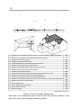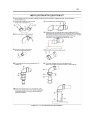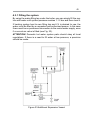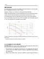
1
1 HARMONY – D USERS, INSTALLATION AND SERVICING INSTRUCTIONS 2 Code No: A.1.2.8i Revision Date: 200114 Publishing Date:200114 3 Thank you for choosing ALARKO brand. This booklet covers room sealed model HARMONY-D natural gas/LPG combination boilers in ALARKO-CARRIER boiler range. In this booklet you will find the instructions for use in USE section and instructions for installation and maintenance in INSTALLATION AND MAINTENANCE section. For long-term and safe use of the boiler, the user must read the USE section of this booklet carefully before using the boiler. Other sections of this booklet are not for the end-user. People or organizations authorized to install, commission and service this boiler must follow the instructions in INSTALLATION AND MAINTENANCE section of this booklet to ensure the correct installation and operation of the appliance. For further information, please consult to the product introduction brochure or authorized dealers and services. Keep this booklet on hand to consult to whenever you may need. 4 TABLE CONTENTS USER INSTRUCTIONS8 1. Introduction8 DECLERATION OF CONFORMITY AND CERTIFICATION 9 TERMS AND CONDITIONS OF GUARANTEE AND SERVICE 9 Guarantee is not valid under below conditions. 9 1.1 Gas Safety10 1.2 Course of Action in case of Gas Leakage 10 1.3 Contents of Packaging12 2. Product Description13 2.1 Technical Data15 2.2 Dimensions16 2.3 Internal Parts of the Boiler 17 2.4 Water Circuit18 2.5 Control Panel19 2.5.1 ON/OFF and Domestic Hot Water Control Knob 19 2.5.2. Central Heating Control Knob 20 2.5.3. Pressure Gauge (Manometer) 20 2.5.4. LCD Display21 2.5.5. Reset Button21 3. BOILER OPERATION22 3.1 Start-Up / Pre-Checks22 3.2 Water Filling22 3.3 Domestic Hot Water Operation 23 3.4 Central Heating Operation23 In Summer: 3.5 Turning the boiler OFF24 3.6 Central Heating System Discharge 24 3.7. Topping-up the system with water 24 INSTALLATION AND SERVICING24 4. INTRODUCTION25 4.1 INSTALLATION RULES25 4.1.1 GENERAL25 .. 5 4.1.2 BOILER LOCATION26 4.1.3 AIR SUPPLY27 4.1.4 OPENING THE PACKAGE & TRANSPORT 28 4.1.5 MOUNTING THE BOILER29 4.1.6 Water and Gas Connections to the Boiler: 29 4.2 FLUE SYSTEM AND INSTALLATION 30 4.2.1 Sitting the Flue Terminal30 4.2.2 Parts of Harmony_D RSF Flue System 33 4.2.3 Standard Supply (concentric horizontal) 34 4.2.4 Additional Kits34 4.2.5 Installing the Standard Supply 37 4.2.6 Installing the Flue System with Straight Extension Kit: 38 4.2.7 Installing Flue System with 90° Turning Kit 41 4.2.8 Installing Flue System with Elevation Kit 42 IMPORTANT NOTES ON FLUE SYSTEMS 44 4.3 COMPONENTS & SYSTEM44 4.3.1 Filling the system45 4.3.2 DOMESTIC HOT WATER46 4.3.2.1 Showers, Bidets, Taps and Mixing Valves 48 4.3.2.2 Water Quality48 4.3.2.3 Water Pressure48 4.4 ELECTRICAL49 4.4.1 ELECTRONIC BOARD WIRING DIAGRAM 51 4.5 CONVERSION TO DIFFERENT GASES 52 5. OPERATING PARAMETERS53 5.1 Programming operating parameters 54 5.1.1 Parameter menu activation54 5.1.2 Parameter selection mode55 5.1.3 Parameter changing mode55 5.1.4 PARAMETERS’ ADJUSTMENT56 5.1.4.1 Parameters Menu Activation56 5.1.4.2 Parameter Selection57 5.1.4.3 Parameter Modification 57 6 5.2 OPERATING ERRORS57 5.2.1 Some Typical Problems58 5.3 PERIODIC MAINTENANCE59 Automatic Control Devices60 6. Use with LPG61 7. COMMISSIONING61 7.1 Pre Checks61 7.2 Start up62 7.3 Setting The Heat Input63 7.4 Maximum and Minimum DHW/CH Input Adjustments (mechanical maximum and minimum) 64 7.5 Final Operational Checks 65 7.6 Commissioning – Heating System 65 7.7 INSTRUCTIONS TO THE USER 66 8. SERVICING66 Appendix A70 FAULT FINDING70 TABLES Table 1 Technical Data15 Table 2 Clearances for boiler installation 26 Table 3 Minimum clearances for cupboard installation. 27 Table 4 Minimum ventilation areas for cupboards 28 without sufficient clearance. Table 5 Setting the Parameters 53 Table 6 Parameter Adjustment55 Table 7 Fault Display57 7 FIGURES Figure 1 Boiler Dimensions16 Figure 2a-b Main Parts of the Boiler/ Front-Backside View 17 Figure 3 Water Circuit Diagram 18 Figure 4 Control Panel Appearance19 Figure 5 DHW Knob19 Figure 6 CH Knob20 Figure 7 Manometer20 Figure 8 LCD Display Screen 21 Figure 9 Hydraulic Group- Manual filling tab 24 Figure 10 Transport & Packaging28 Figure 11 Mounting Schematic with essential dimensions. 29 Figure 12 Gas & Water Connections 30 Figure 13 Flue Terminal Dimensions32 Figure 14 The Parts of the Flue Kit 33 Figure 15 Wall Connections36 Figure 16 Extensions & Elbow 36 Figure 17 Standard Flue Kit Installation 37 Figure 18 Extension Flue Kit Installation 39 Figure 19 Shortening the Ducts 40 Figure 20. 90º Turning Kit Installation 41 Figure 21. Elevation Kit Installation 43 Figure 22 a) Additional Expansion Vessel, b) Methods of Filling the System 45 Figure 23 Volumetric Flow Rate & Pressure Difference Relation for the Circulation Pump 46 Figure 24 Main Board Diagram 51 Figure 25 Burner Pressure/ Heat Input Diagram 63 Figure 26 Gas Modulator64 Figure 27 Burner Plates, Igniters and Flame Sensors 68 8 USER INSTRUCTIONS 1. Introduction In this booklet you will find users and servicing instructions of your new Harmony – D digital screen combination boiler and some useful information and technical data about it. Harmony combination boilers are the results of development, production and marketing experience, which have resulted in the current highly efficient and user-friendly models. The compact size and pleasing appearance enable them to be fitted in a wide range of locations. Despite its compactness, all inner pipe-work and components are designed to allow easy access for the service engineer. The appliance is suitable for sealed systems only. Our authorized seller and services will give you the enough information about use and maintenance after setting up the boiler. You can ask any further question to them. Our experts will be glad to answer your questions. In order to use the boiler in safe, high efficiency and economic way for a long life period; please read these instructions carefully and obey the safety rules and warnings. In addition to the users instructions in this booklet, there are also technical data and introductory information about the boiler. Read the instructions and other labels carefully, before starting the boiler. Take into consideration all the warnings. Do not handle the parts of the boiler in a different way than specified in the instructions. 9 DECLERATION OF CONFORMITY AND CERTIFICATION Alarko Carrier manufacture boilers referred to in this booklet are produced in conformity with below: EC Directives and can hold the CE mark. 2009/142/EC Gas Appliances Directive 92/42/EEC Efficiency Directive 2004/108/EC Electromagnetic Compatibility Directive 2006/95/EC Low Voltage Directive The appliances are certified to comply with the requirements of EN 297, EN 483 and EN 625 using the gas categories listed below: 2H and 2E; G20 gas with a governed gas supply at 20 mbar inlet pressure 3 B/P; any mixture of G30 and G31 gases with a governed gas supply at 29-mbar-inlet pressure 3+; G30 / G31gases with non-governed gas supplies at 29 / 37 mbar inlet pressures, respectively. TERMS AND CONDITIONS OF GUARANTEE AND SERVICE Your boiler is guaranteed for material defects and mechanical failure as written on the Guarantee Form. The guarantee is only valid if the appliance is installed in accordance with this manual. Guarantee is not valid under below conditions. • Installation by unauthorized persons. • Hazards due to service by unauthorized persons. • Hazards due to natural disaster. • Hazards due to bad weather conditions, especially frost, unless instructions in this booklet are obeyed. • Damaged or changed serial number of boiler. • Incorrect installation, use and maintenance with respect to the instructions and the regulations in force. • Boilers produced for display and exhibition purposes. 10 • Absence of Guarantee Form. • The transportation risks belong to the customer if boiler is sent to service by customer and belongs to the service if boiler is taken by service. 1.1 Gas Safety It is the law that all gas appliances must be installed by a competent person in accordance with the current rules and regulations in force in the country of destination. With the same scope, any gas conversion process carried out on the boiler must be done by a competent person as well. These appliances are certified to comply with the requirements of EN 483 and EN 625 using gas categories 2H, 2E, 3B/P, 3+, 3B and 3P with prescribed gas inlet pressures. No other gas use condition is allowed for the boiler. The particular gas type that the boiler is already adjusted to is written on its data badge, unless it is converted to another gas by a competent person. Make sure that the boiler is not used with a different gas, other than which it is adjusted for or it is finally converted to. 1.2 Course of Action in case of Gas Leakage If you smell gas or the gas alarm device signals; • Be calm, • Turn off the appliance, • Open all the doors and windows to vent the room, • Extinguish any flame, • Close gas valves of any appliance and at the apartment inlet, • Do not light anything and do not smoke, • Do not switch on or off and electrical device, • Do not attach or pull out electric plugs, do not ring the bell, • Do not use the telephone where the gas smell exists, • Contact your gas supplier and fire brigade and explain the situation. 11 Warnings! This appliance must only be used for the intended purpose of manufacture. Alarko Carrier Sanayi ve Ticaret A.Ş. does not take any responsibility for the damage or injury on persons, animals or objects caused by incorrect installation, service or maintenance, use except for the intended purpose or disobeying any of the warnings within this booklet. Spaces allowed for installing a gas-fired boiler are defined by international and/or local regulations and rules of gas distribution companies. You can supply detailed information about those limitations from your installer. For your own safety, do not ask the installer to install your boiler to prohibited spaces. Before gas installation, a suitable gas installation project has to be prepared and approved according to the requirements of local gas distribution organization. After approval of local gas distribution organization and precise application of installation, have your boiler commissioned by an Authorized Service. Commissioning is a free service. Do not let unauthorized people to interfere or service the boiler. Gas conversion process, if necessary, must be made by an authorized service only. Conversion is paid by the end-user. Keep flammable and combustible objects, either liquid or solid, away from the boiler. Do not place cooker near the appliance and protect the boiler from direct vapor. Do not use any spray, chemical solvent, chlorinated cleaner, paint or adhesive near the boiler. The boiler is to be connected to an earthed 230 V 50 Hz electric supply. To enable the frost protection function in winter when the weather temperature might fall below 0°C, do not turn the boiler off. Filter must be installed at the water inlet of the boiler to protect the pump and the filter must be cleaned periodically. The pump shaft should be 12 rotated manually before starting the boiler after a long time of inactivity. Apply the authorized service to take more information about this process. If you charge the central heating system with hard water, this may cause blockage of the heat exchanger. Mains supply water should not exceed 15° French hardness value. To prevent any corrosion, pH value of the water should be between 8,2 - 9,5, conductivity should be less than 30 μS/cm, and oxygen content should be less than 0,1 gr/m³. Hot water circuit does not need a pressure relief valve. On the other hand, pressure should not exceed 6 bars. In case of doubt, a pressure regulator should be fitted. Consult your installer on this issue. 1.3 Contents of Packaging The following items below are included in the package. Check if any item is missing. • Hanging bracket, connection screws (4 pcs) and wall plugs (4 pcs), • Installation, operating and maintenance Instructions • Warranty Document, • Standard Flue System is supplied in a separate package. 1.4 ECONOMY MEASURES Your boiler is designed and manufactured to minimize the gas consumption. For further saving below are recommended: • Your boiler is adjusted to 20.726 kcal/hour of output capacity. Down rating of the heating capacity will save in houses where heating requirement is less. Consult the authorized service for adjustment. • Use of thermostatic radiator valves or flow balance of radiators brings additional saving due to homogenous heat distribution over the house. • Setting the temperature control knobs between the positions 4 and 6 reduces fuel consumption. On the other hand, they can be set to 13 other positions due to various heating and hot water requirements with no inconvenience. • Lower setting of DHW temperature reduces fuel consumption. 2. Product Description Harmony-D is a room sealed mono-thermal exchanger combination boiler with 24.1 kW nominal output to provide both central heating and domestic hot water. Despite the complexity of the system, all inner pipe work and components are designed to allow easy access for the service engineer. Ignition of the burner is provided automatically by the electronic ignition system. The latest design of main integrated electronic board controls all safety and operational functions automatically. A diagnostic section monitors boiler operation mode and indicates faults to the user by a Carrier© blue LCD screen located on the fascia panel. A degree of frost protection is built into the boiler controls. When the boiler temperature falls under 6°C, the boiler starts to operate until a temperature of 15°C is reached on CH side. Additionally, there is also an antifreeze DHW protection function that operates under 5°C until 8°C is reached. These control functions prevent the boiler from freezing. When there is no heat demand during 24 hours, pump is activated by the control board for 30 seconds to prevent the pump from getting jammed due to inactivity. User controls are on a modern, aesthetic, and functional control panel on the boiler front. The controls allow the user to set the central heating temperature to between 30°C and 80°C and the DHW temperature to between 35°C and 60°C. Boiler has got those features: • Continuous full modulation for both domestic hot water and central heating, • Three ignition attempts, (one ignition attempt for operating with LPG) 14 • High temperature limit thermostat safety, • Temperature control with domestic hot water and central heating sensors, sensor fault warnings, • Flame detection, • Heating and domestic hot water frost protection, • Central heating and domestic hot water pump overrun, • Energy saving circulation pump, • Pump jamming prevention, • Central heating low and high pressure safety, • Domestic hot water low pressure safety, • Automatic by-pass, • Hermetic pipe blocking and fan malfunction safety, • Suitable for use with under floor heating. The technical data is shown in Table 2.1. HARMONY_D USERS INSTALLATION AND SERVICE MANUAL 15 2.1 Technical DataData 2.1 Technical TableTable 1 Technical Data 1 Technical Data Product Model HRD Flue System/Type Hermetic/C12 (x) Gas Class II2H3B / P Reference Gas G20 Maximum Heat Power (Net) kW 24.1 kcal/hour 20726 Efficiency at 100 % Load % 93.8 Maximum heat load (Net) kW 25.7 Minimum heat power kW 10.11 Minimum heat load (Net) kW 11.8 Maximum gas inlet pressure mbar 20 Burner pressure for maximum load mbar 11.5 Burner pressure for minimum load mbar 1.7 Injector Diameter mm 1.35-0.80 Ignition System Electronic NOx Class 3 CENTRAL HEATING SYSTEM DATA Pressure (max / min) bar 3.0/0.3 Expansion Tank Volume / Pressure lt./bar 6.0/0.2 Maximum Water Temperature °C 85 Temperature Range °C 30-80 or 30-50 Frost Protection Operation Temperature °C 6 DOMESTIC HOT WATER SYSTEM DATA Temperature Range °C 35-60 Pressure (max / min) bar 6/0.2 DHW minimum flow rate lt./min. 2.2 DHW Flow Rate at a Temp. rise of 30°C lt./min. 12 PHYSICAL DATA Flue Diameter Overall Dimensions (Width, Height, Depth) Weight – Net / Gross (except flue set) mm. 100 (suction) / 60 (discharge) mm. 400, 700.5, 340 kg. 30.6 / 33.5 Heating – Supply / Return Connections in. 3/4" DHW – Input / Output Connections in. 1/2" Gas Connection ( via Kit ) in. 3/4" (1/2") Safety Valve Connection in. 1/2" ELECTRICAL DATA Electrical Connection V/Hz Internal Fuse Rating A 4 Power Consumption W 110 Electrical safety class 2.2 Dimensions 230/50 IP X3D 16 HARMONY_D USERS INSTALLATION AND SERVICE MANUAL 2.2 Dimensions Figure 1 Boiler Dimensions 2.3 Internal Parts of the Boiler 17 HARMONY_D USERS INSTALLATION AND SERVICE MANUAL 2.3 Internal Parts of the Boiler The main parts of the boiler and water circuit are shown in Figures 2a and 2b (Front view, The view) mainand parts of 3. the boiler and water circuit are shown in Figures 2a backside Figure and 2b (Front view, backside view) and Figure 3. Figure 2a-b Main Parts of the Boiler/ Front-Backside View 18 2.4 Water Circuit HARMONY_D USERS INSTALLATION AND SERVICE MANUAL 2.4 Water Circuit Figure 3 Water Circuit Diagram 19 2.5 Control Panel The control panel is specially designed considering both easy setting of the boiler with only two knobs and a reset button on it and an aesthetic outside appearance with a surrounding blue LED lightening along the panel border. This lightening feature is arranged to be ON by default, while there is flame in the boiler. This property can also be rearranged according to customers liking so that the LED light can be ON or OFF continuously all the time. Warning!: If LCD light is ON, LED light will be OFF. They do not give light simultaneously. During setting up of the DHW or CH temperatures with control panel knobs, LCD panel will automatically starts emitting Figure 4 Control Panel Appearance light and LEDs will be OFF. LED light will start to give light again 5 seconds after setting of the control panel with knobs, according to the relevant parameter input described above. 2.5.1 ON/OFF and Domestic Hot Water Control Knob This feature allows the user to ON / OFF the boiler and set the desired temperature for the domestic hot water. When the blue pin on DHW knob indicates the gap under the temperature legend ‘1’, boiler is OFF and not only the central heating mode but also the domestic hot water mode is OFF position. When the indicator knob position passes over the legend ‘1’, domestic hot water mode is ON. From number 1 to 7 domestic hot water temperature can be adjusted. Turning clockwise increases the set temperature. Figure 5 DHW Knob 20 2.5.2. Central Heating Control Knob This feature allows user to set the desired temperature for the central heating system water. When central heating knob indicates the region under the legend ‘1’, central heating mode is ‘OFF’. When it passes over the position of legend ‘1’, central heating turns to mode ‘ON’. (Note that domestic hot water knob should not be in ‘OFF’ position to ‘ON’ the central heating mode.) From number 1 to 7 central heating water temperature can be adjusted. Turning clockwise increases the set temperature. When the indicator knob position passes over the legend ‘1’, domestic hot water mode is ON. From number 1 to 7 domestic hot water temperature can be adjusted. Turning clockwise increases the set temperature. Figure 6 CH Knob 2.5.3. Pressure Gauge (Manometer) The pressure gauge on the control fascia panel indicates the central heating system pressure. The normal running pressure is around 1 bar (cold) indicated by the solid Figure 7 Manometer green line. 1) Lower red region: Indicates that water pressure is not sufficient. Boiler doesn’t work in that region. It should be pressurized (filled) via water supply into the system. 2) Lower green region: When the boiler isn’t working, water pressure should be in that region. 3) Upper green region: Indicates the maximum pressure level while the boiler is working. 4) Upper red region: Indicates that water pressure is over the required level. Water should be removed from the system until the manometer shows the lower green region. If the manometer shows the upper solid red line, 3-bar safety valve removes the water from the system automatically. 21 2.5.4. LCD Display LCD Display shows boiler operating mode, temperature and indicates the faults instantly as they arise. Digital numbers can be monitored on the blue background screen during setting the CH and DHW heating temperatures or parameters of the boiler. When the boiler is OFF, power of the screen is cut off. When there is CH demand, “ ” sign appears on the screen and temperature of central heating water on heat exchanger exit can be read as Celsius degrees. When there is DHW demand, “ ” sign appears on the screen and temperature of sanitary water on heat exchanger exit can be read as Celsius degrees. Figure 8 LCD Display Screen During the operation of the boiler “ ” sign displays continuously. The monkey wrench sign “ ” appears in some cases of operating errors, indicating that there is a need for the service. 2.5.5. Reset Button Boiler locks itself in the below conditions and waits for the user interference. 1) Failure of three consecutive firing attempts. 2) Exceed the high temperature limit. In those conditions the user should control if there is an operating error that requires resetting of the boiler. Following this, the boiler can be started by switching the reset button ( ). 22 3. BOILER OPERATION 3.1 Start-Up / Pre-Checks • Check if the electricity, gas valves and water valves are open. • Open the radiator valves. • Check if there is mains water supply. If mains water supply is OFF, heating system water might flow to the mains water installation, emptying the radiators. 3.2 Water Filling WARNING! Do not charge water while the boiler is running. Wait for the boiler to cool down before filling water. • If the pressure gauge shows below the lower green zone, water must be charged to the boiler and the heating system. To do this; Turn the water-filling tap at the boiler bottom slowly to open. WARNING! If you fill the system very rapidly, air may collect in the heating system or in the boiler. • Water should be charged until the pressure gauge indicates green region pressure. Do not forget to turn the filling tap off after water filling is completed. • Turn the boiler ON. • Check the pressure on pressure gauge as the system heats up after a while. Pressure should not exceed green region. • Open the air release taps on the radiators and at the highest point of installation, if any. Wait until water drains continuously before closing the air release taps. • Check “insufficient system pressure” code and pressure gauge again. If the code appears, charge water to the system again. WARNING! If there is noise in the boiler or installation, repeat air-releasing process. WARNING! It is recommended that the boiler be turned OFF during air releasing process. • Check the heating system pressure regularly. 23 3.3 Domestic Hot Water Operation • Turn the DHW control knob to ON ( ) position. Sign “ ” will appear and number on the screen will indicate set temperature of sanitary water. • When there is a call for hot water as a hot water tap is opened; the boiler senses the flow to the taps and, if it is in stand-by, automatically starts the ignition sequence. “ ” sign will appear on the screen. • The 3WV valve shuts down the heating system and the full boiler power becomes available to meet the hot water demand. • The domestic hot water sensor controls the heat input to maintain the hot water at the temperature level selected by the user via the domestic hot water control knob. • A temperature range between 35°C and 60°C can be set. 3.4 Central Heating Operation • Turn the DHW control knob to ON ( ) position. The LCD screen will turn on with its blue light. • Turn the central heating control knob ON position ( ). The system pump will now run and the boiler control algorithm will start the automatic ignition sequence. Set the heating temperature control to the desired level. A temperature adjustment is possible between 30°C and 80°C. The boiler control algorithm will now maintain the set temperature, modulating the heat input to match the heating load. When the desired water temperature is reached and read by the sensor, the boiler will shut down. The system pump will continue to run to dissipate the heat from the boiler. In Summer: When there is no call for heating but only for hot water, e.g., in summer, turn the CH control knob to the OFF position, but leave the DHW control knob in the ON ( ) position. 24 3.5 Turning the boiler OFF • Turn both the CH control knob and the DHW control knob to the OFF position. • Turn the gas and electricity supplies to the boiler OFF. • If the boiler is switched OFF when there is a likelihood of frost; water in the boiler should be drained off by opening the house central heating drain tap. 3.6 Central Heating System Discharge Do the following in case of a discharge of the central heating system water; • Turn on the drain tap at the bottom of the central heating system. • Open the air release taps of radiators. Begin from top radiator to bottom one. • Close the air release taps after draining the water. ATTENTION! It is not recommended to discharge the system except for the necessary events. • When the boiler is switched off at the switch on the control panel, the word OFF appears on the display. The D.H.W and central heating frost protection system, nevertheless, remain enabled. If the boiler was previously on, it is switched off and the post-ventilation, pump overrun, circulation pump and three-way valve inactivity protection functions are enabled. 3.7. Topping-up the system with water The water pressure in the central heating circuit must be checked in case of a DHW request error notification. The pressure gauge located in front of the pump, should be within the green region and must not be less than 1 bar. If there is insufficient water in the boiler, the error code F0 (Table 7) will appear on the display indicating that there is not enough water in the system. Figure 9 Hydraulic Group- Manual filling tab 25 To bring the system back up to pressure, open the manual filling tap (Fig.9) and check the system pressure until it reaches to 1 bar. Close the filling tab, when the operation is complete. INSTALLATION AND SERVICING 4. INTRODUCTION Please read these instructions carefully to ensure the correct installation and operation of the appliance. These instructions cover the room sealed HARMONY-D model in the ALARKO-CARRIER boiler range. This Installation and Servicing Manual contains information on installation, commissioning, servicing procedures, description of main parts, wiring diagrams and electrical connections, adjustments and fault finding. A detailed fault finding section is included towards the end of the manual. Before commencing the installation of the boiler check the labels and data plate on the boiler to ensure that the appliance is compatible with the local gas and electricity supply conditions. In the case of any uncertainty, contact with the local gas supplier. 4.1 INSTALLATION RULES 4.1.1 GENERAL 1) Current Gas Safety (Installation and Use) Regulations state that all gas appliances must be installed by a competent person in accordance with the regulations and rules in force in the countries of destination. 2) Failure to install appliances correctly could lead to prosecution. 3) These appliances must be installed in accordance with relevant National and local rules and regulations in force. The manufacturer’s notes must not be taken, in any way, as overriding statutory obligations. 4) To ensure that the installation will perform to the highest standards, the system and components should also conform to any relevant National and/or local standards in addition to those mentioned in the instructions. 26 5) The advice and instructions given in this document covers, as far as possible, the foreseeable situations, which may arise. Contact manufacturer for further advice if required. 6) Installation using the standard flue kit is described in the main text of .2 BOILERthese LOCATION instructions. NO OTHER FLUE KITS OR EXTENSIONS MAY BE USED WITH THIS APPLIANCE This appliance may be installed in any room provided that attention is drawn to requirements of theappliances relevant national andwith local rules, SYSTEMS standards ONLY. and regulations in force 7) These are for use SEALED the countries of destination. Where it is installed in a room containing a bath or show 4.1.2 switch BOILER any electrical orLOCATION appliance control using mains electricity must not be able to touched by a person using or shower. 1) This appliance the maybath be installed in any room provided that attention is is drawn to the requirements of installation. the relevant national and local rules, The appliance not suitable for external standards and regulations in force in the countries of destination. The appliance does itnot require in any special wall protection. Where is installed a room containing a bath or shower, any elec- trical switch or appliance control using mains electricity must not be The wall must be capable of supporting the weight of the appliance. (See Table 1.) able to be touched by a person using the bath or shower. Always consider the possible need tofordisconnect the pipes from the appliance a 2) The appliance is not suitable external installation. installation. 3) The appliance does not require any special wall protection. The following clearances must be available for installation and for servicing 4) The wall must on be Table capable2 of supporting the weight of the appliance. (See Table 1.) 5) Always consider the possible need to disconnect the pipes from the appliance after installation. 6) The following clearances on Table 2 must be available for installation and for servicing. Table 2 Clearances for boiler installation Clearances Above the casing Below Right hand side Left hand side 200 mm 100 mm 30 mm 30 mm 7) If the boiler is to be installed in a timber framed building it should be fitted in accordance with the relevant National and boiler is to be rules installed in a timberinframed it should be fitted local and regulations force, if building any. If the with the relevant National and local rules and regulations in force, if any. in accorda No combustible surface must be within 75 mm of the casing. If there is need to adjust n a combustible surface, follow the clearances on Table 2. The appliance can be installed in a cupboard used for airing clothes provided that 27 HARMONY_D USERS INSTALLATION AND SERVICE MANUAL 8) No combustible surface must be within 75 mm of the casing. If there is need to adjust near a combustible surface, follow the clearances 10) The airing space must on Table 2. be separated from the boiler space by a perforated non-combustible partition. Expanded metal or rigid wire meshes are acceptable provided that the major 9) is The appliance can be installed in a cupboard used for airing clothes dimension less than 13 mm. provided that the requirements of relevant National and local rules 11) Not withstanding those rules and regulations, room sealed appliance may be fitted in a and regulations (if any) are maintained. compartment with no vents as long as the minimum clearances stated in Air Supply, are 10)The airing space must be separated from the boiler space by a maintained. perforated non-combustible partition. Expanded metal or rigid wire meshes are acceptable provided that the major dimension is less than 13 mm. 11)Not withstanding those rules and regulations, room sealed appliance may be fitted in a compartment with no vents as long as the minimum clearances stated in Air Supply, are maintained. AIR SUPPLY 4.1.3 AIR4.1.3 SUPPLY The appliance not require separate for combustion The does appliance does anot requirevent a separate vent forair. combustion air. The appliance can be in a cupboard no for vents for cooling butminimum The appliance can be fitted in fitted a cupboard with nowith vents cooling but the the minimum clearances must be increased to those given below. (Note: clearances must be increased to those given below. (Note: the clearances at the front are for a clearances at the front are for a removable panel, e.g. a door). removablethe panel, e.g. a door). Table 3 Minimum clearances for cupboard installation. Above the flue turret In front Below Right-hand side Left-hand side 150 mm 250 mm 200 mm 75 mm 75 mm If the appliance is to be fitted in a cupboard or compartment with less clearance those the table or above (minimumwith clearances are given If the appliance is to than be fitted in in a cupboard compartment less clearance than those in in the “Boiler Location” section) then permanent air vents for cooling the table above (minimum clearances are given in the “Boiler Location” section) then located at high and levels, vents permanentare air required. vents for Both cooling are required. Bothlow located at all high and connecting low levels, all vents directly to outside air or to a room. Both vents must pass thesame same connecting directly to outside air or to a room. Both vents must pass totothe room or be room or be on the same wall to the outside air. on the same wall to the outside air. The minimum free areas required are given in Table 4: Table 4 Minimum ventilation areas for cupboards without sufficient clearance. Position of air vents High level Air from another room 260 cm² Air direct from outside 130 cm² If the appliance is to be fitted in a cupboard or compartment with less clearance than those in the table above (minimum clearances are given in the “Boiler Location” section) then permanent air vents for cooling are required. Both located at high and low levels, all vents connecting28directly to outside air or to a room. Both vents must pass to the same room or be on the same wall to the outside air. The minimum free areasfree required given inare Table 4: in Table 4: The minimum areasare required given Table 4 Minimum ventilation areas for cupboards without sufficient clearance. Position of air vents High level Low level Air from another room 260 cm² 260 cm² Air direct from outside 130 cm² 130 cm² 4.1.4 OPENING THE PACKAGE & TRANSPORT HARMONY_D USERS INSTALLATION AND SERVICE MANUAL Refer to the following diagrams. See Fig. 10. TRANSPORT AND PACKAGING The boiler is packaged in a cardboard box. Warning signs are to be observed during transport and storing. MAX. 4 Do not step on the box. When the boxes are placed on the floor,arrows should point upwards. Maximum four boxes can be placed on top of each other. Do not drop the box. Do not let the box get soaked. 19 - The boiler can be carried by two people by uplifting it through the two holes on both sides. - The boiler should be stored in a place free of dust and moisture and should not be taken out of its package until it is to be installed. - When stored,maximum four boxes can be placed on top of each other. - Boilers can be installed following the completion of water and electric systems. OPENING THE PACKAGE 1 2 Put the box on the floor with the symbol " " on top. 3 Cut the bands to open the box. 4 Open the nylon wrapping and take the upper moulded packaging out from the box. Take the boiler out by holding from two sides on both ends. DO NOT TRY TO LIFT FROM THE MIDDLE! Figure 10 Transport & Packaging 29 4.1.5 MOUNTING THE BOILER Determine the right position for the wall-hang boiler with respect to the required clearances for servicing, general access and position of the flue. Fix the mounting bracket to the wall, with the fixings provided, enHARMONY_D USERS INSTALLATION AND SERVICE MANUAL suring that it is horizontal. Hang the boiler on the mounting bracket and fix the boiler to the wall from the bottom. (See Fig. 11) Figure 11 Mounting Schematic with essential dimensions. 4.1.6 Water and and Gas Connections to the Boiler: 4.1.6 Water Gas Connections to the Boiler: CH water connections should be¾’’, made viaDHW ¾’’, connections gas and DHW connecCH water connections should be made via gas and should be made via tions should be(see made via For ½’’ copper isolation valves ¾” (see 12). For correspond copper ½’’ isolation valves Fig. 12). installations and Fig. ½” dimensions toinstallations Ø 22 and Ø 15 Take care that the seals ¾”mm andrespectively. ½” dimensions correspond to Øprovided 22 andare Ø correctly 15 mm fitted rebetween the installationcare kit fittings and seals the connection tails.are correctly fitted between spectively. Take that the provided Purge the gas supplykit before finally connecting the appliance. The complete installation must the installation fittings and the connection tails. be tested for gas soundness. Purge the gas supply before finally connecting the appliance. The com- Thoroughly flush the heating system and the cold water mains supply in accordance with the plete installation forensure gas soundness. recommended methods.must Afterbe thistested operation, that the water filters at the water inlet are cleaned before finally the boiler to the and waterthe installation. Thoroughly flushconnection the heating system cold water mains supply Check that no dirt is left the gas or water pipe work as thisAfter could this cause operation, damage to the in accordance within either the recommended methods. appliance. 30 ensure that the water filters at the water inlet are cleaned before finally connection the boiler to the water installation. Check that no dirt is left in either the gas or water pipe work as this could cause damage to the appliance. HARMONY_D USERS INSTALLATION AND SERVICE MANUAL Figure 12 Gas & Water Connections 4.2FLUE FLUE SYSTEM AND INSTALLATION 4.2 SYSTEM AND INSTALLATION 4.2.1 Sitting the Flue Terminal 4.2.1 Sitting the Flue Terminal The flue must be installed according to national and local regulations The flue must be installed according to national and local regulations (See Fig. 13). (See Fig. 13). The terminal must not cause an obstruction or the discharge cause a nuisance. The terminal must not cause an obstruction or the discharge cause a If the terminal is fitted within 1000 mm of a plastic or painted gutter or within 500 mm of nuisance. painted eaves, then an aluminum shield at least 1000 mm long should be fitted to the underside of the gutter or painted surface. If the terminal is fitted within 1000 mm of a plastic or painted gutter or The terminal should be fitted less than 2 meters above a surface to which people have access. In certain weather conditions a terminal may steam and sitting where this could cause a nuisance should be avoided. Take care to ensure that combustion products do not enter ventilated roof voids. 31 within 500 mm of painted eaves, then an aluminum shield at least 1000 mm long should be fitted to the underside of the gutter or painted surface. The terminal should be fitted less than 2 meters above a surface to which people have access. In certain weather conditions a terminal may steam and sitting where this could cause a nuisance should be avoided. Take care to ensure that combustion products do not enter ventilated roof voids. Where elongation of the flue pipe is a necessary, only original extension pipe and elbow must be used. The flue system can be installed from inside the room without access to the external wall and regardless of the wall thickness providing that a suitable wall liner is fitted. ATTENTION! Flue terminal must be fitted with 3% downward inclination to prevent rain leaking in to the boiler. regardless of the wall thickness providing that a suitable wall liner is fitted. ATTENTION! Flue terminal must be fitted with 3% downward inclination to prevent rain leaking in to32 the boiler. C A M B,C B,C F M G F A E K L K A K F M G G L G Q 430 mm MIN. J H,I D,N F P R O K O G A B C D E F G H I J K L M N O P Q R Distance to an openable window,air vent or any other ventllation opening from below Distance to roof gutter or drainage and soil pipes from below Distance to eaves from below Distance to balconies from below Horizontal distance to vertical drainage and soil pipes Distance to inner and outer corners of walls Distance to adjacent ground or balcony level from above Distance from a surface facing the terminal Distance from facing terminals Horizontal distance to an opening (door/window)under the lean -to roof Distance to another terminal on the same vertical axis Distance to another terminal on the same horizontal axis Distance to an adjacent opening such as a door or window on the same horizontal axis Distance to lean -to roof from below From adjacent wall From adjacent opening window From another terminal Minimum height 300 75 200 200 150 300 300 600 1200 1200 1500 300 300 600 300 1000 600 300 All dimensions are in mm. Figure 13 Flue Terminal Dimensions See figure 14 to identify the parts of the flue kit. Flue kit item numbers in this See figurefigure 14 to are identify parts of the installation flue kit. Flue kit item numbers in this figure are used used the in the following guides. in the following installation guides. 33 HARMONY_D USERS INSTALLATION AND SERVICE MANUAL 4.2.2 Parts of Harmony_D RSF Flue System 4.2.2 Parts of Harmony_D RSF Flue System HARMONY-D HERMETİK KOMBİ BACA SETİ 58990220076 HARMONY-D YÜKSELTME SETİ 58990220076 HARMONY-D HERMETİK KOMBİ BACA SETİ 58990220076 Figure 14 The Parts of the Flue Kit 34 4.2.3 Standard Supply (concentric horizontal) The appliance is supplied with a standard concentric air and flue duct system suitable for flue lengths of up to 725mm (28.5 in) measured from the centre of the fan outlet of the boiler to the outside surface of the wall (or window). The duct assembly is connected to the boiler via a turret elbow, which can be positioned to exit the boiler in any horizontal direction (see Fig. 15). For flue lengths less than 650mm (25.5 in) the outlet terminal duct must be shortened. Shorten the duct by cutting approximately equal lengths from both halves as required. 4.2.4 Additional Kits The following additional concentric kits are available as optional extras and these flue kits may be used with the standard flue kit to give an extensive range of flue options. Examples are illustrated in Fig. 14. a) Extension Duct: With the use of concentric flue extension ducts (see Fig.14), the total flue length of the system measured from the centre of the fan outlet of the boiler to the outside surface of the wall (or window) can be increased up to 3000 mm (118 in) (See Fig. 14). Each 1000 mm extension duct extends the flue length by 973 mm. and each 500 mm extension duct extends the flue length by 473 mm. b) 90o Elbow: Additional 90° elbows can be added to the flue system to allow additional bends in the flue system to give greater flexibility in the location of the boiler. The resistance of the bends must be taken into account when determining the permissible maximum length of the flue system. A 90o elbow has an “equivalent length” of 973 mm, one 1000 mm extension duct. No more than two elbows should be used. c) Elevation Duct: This is to be used for elevated horizontal flues if required. With standard elevation duct, 300 mm elevation is possible from the top of the boiler before turning to the horizontal direction with elbow. NOTE: Variations may be used providing that the following rules are strictly adhered to: 35 1. The maximum permissible horizontal length of the flue system is: 3000mm. This length has to be considered 973 mm less for the use of each additional 90° elbow. 2. The standard terminal must always be fitted horizontally. The flue system must only terminate in a horizontal position. However 900 elbows may be used to drop the height of the flue system by 500 mm. 3. The flue system must use either a flanged elbow or a flanged elevation duct at the entry / exit to the appliance. 4. All joints must be correctly made and secured in accordance with the installation instructions in “Flue System Installation” section. Refer to Figs. 15 & 16 to determine which flue options are required before commencing the installation. HARMONY_D USERS INSTALLATION AND SERVICE MANUAL 36 Figure 15 Wall Connections Figure 16 Extensions & Elbow 27 HARMONY_D USERS INSTALLATION AND SERVICE MANUAL 37 4.2.5 Installing the Standard Supply 4.2.5 Installing the Standard Supply Each boiler is supplied with standard flue system for flue lengths up to 725 mm. See Fig. 17 Each boiler is the supplied withflue standard systemwill for be fluemade lengths up to to assemble and install standard system.flue Reference to additional kits 725 mm. See Fig. 17 to assemble and install the standard flue system. where necessary. Reference will be made to additional kits where necessary. Figure 17 Standard Flue Kit Installation 38 ATTENTION! Step 3 of Fig.17 shows how to fit the terminal duct from inside the room where access to the outside wall is not possible. Such a sliding operating can be done providing that the optional wall liner is used. (This is required to seal any cavity and to allow the sealing ring to pass through from inside and provide an adequate external seal). The wall liner is a tube of 130 mm diameter with a wall thickness of 0.8 mm. This step may be skipped where outside wall is accessible and the terminal duct can be pushed through the wall from outside. In this case, an adequate smaller hole can be drilled on the wall to be able to pass the Ø100 mm terminal duct. 4.2.6 Installing the Flue System with Straight Extension Kit: In case the total length required for a straight outlet from the wall is more than 725 mm, 500 and/or 1000mm extension kits should be used with the standard kit. Refer to Fig. 18. HARMONY_D USERS INSTALLATION AND SERVICE MANUAL 39 Figure 18 Extension Flue Kit Installation Before installing the flue systems, either standard supply or with additional extensions and turns, cutting operation might be necessary to shorten the flue ducts. Determine the cutting length as described in other figures and referring to Fig.19 below to see the cutting operation. 40 Before installing the flue systems, either standard supply or with additional extensions and turns, cutting operation might be necessary to shorten the flue ducts. Determine the cutting length as described in other figures and referring to Fig.19 below to see the cutting operation. Use HARMONY_D USERS AND SERVICE MANUAL aluminum sawINSTALLATION and always ensure that the cut is square and free from burrs or debris. Figure 19 Shortening the Ducts 41 4.2.7 Installing Flue System with 90° Turning Kit It is possible to install the flue system with 1 or 2 pieces of 90° turns between the boiler and the wall, provided that the total lengths allowed are not exceeded. Refer to Fig.20 for installation. HARMONY_D USERS INSTALLATION AND SERVICE MANUAL INSTALLATION WITH 90 ° TURNING KIT(S) The flue system can be installed without any 90° turning kit for positions shown in Fig.A below. 1 or 2 90° turning kit has to be used in positions like in Fig.B where the line from centerline of boiler outlet to the outlet wall surface is not perpendicular. Maximum total lenght "M+L" can be 2200 mm. for installations with one turning kit and Maximum total lenght "M+N+L" can be 1200 mm. for installations with two turning kits. L Fig.A Fig.B A N B B C M L M A 1 Measure lenght "L" from the wall outlet point (A) back to the 90° turning point (B) at the place of installation and install the terminal duct according to this lenght. Installation is done as described in Fig.14 or Fig.15 according to lenght "L". 15 Use elbow (15) instead of elbow with flange (1). B A B For a required "N" distance; Prepare straight inner duct (19)of "N - 132" lenght and straight outer duct(18) of "N - 172" lenght. Refer to Fig.17 for cutting operation. Fit both inner and outer cut straight ducts to elbows (15) at both ends with elbow seals (9) and clamps (7) and secure the clamps with screws(8). N 2 (For installation with two turns) C B 15 9 7 7 9 18 19 9 15 C 8 3 To complete the installation from turning point to the boiler for a required lenght "M", prepare straight inner duct of "M - 132" lenght and straight outer duct of "M - 172" lenght. Complete the installation as described in step2 between the elbow (15) and the elbow with flange (1). (To achieve this distance, an extension kit of necessary lenght can be used between the elbow with flange and the straight ducts.) 1 15 1 M 4 Secure the flue system from the elbow (1) to here with 4 self-tapping screws, such that the elbow gasket (6) will seat in between. 6 Figure 20. 90º Turning Kit Installation 4.2.8 Installing Flue System with Elevation Kit 42 4.2.8 Installing Flue System with Elevation Kit It is also possible to elevate the flue system on top of the boiler before it makes the first turn to its horizontal path. Flue elevation kit has to be used for this purpose and it can be applied to any of the standard, extended and 90° turning flue systems described in the three sections above. Refer to Fig.21 to carry out the operation. The figure shows how to provide the elevation and this operation will only replace the final assembly between the elbow with flange and the boiler in other installations described in Figs.17, 18 and 20. HARMONY_D USERS INSTALLATION AND SERVICE MANUAL elevation and this operation will only replace the final assembly between the elbow with 43 flange and the boiler in other installations described in Figs.17, 18 and 20. Figure 21. Elevation Kit Installation 44 IMPORTANT NOTES ON FLUE SYSTEMS a) Flue terminal must be fitted with 3% downward inclination towards outside to prevent penetration of rain. b) Failing to comply with these instructions will invalidate the appliance certification and therefore may contravene the appropriate EC legislation and local statutory requirements. c) After the flue system is completely installed, check that the terminal is correctly located on the outside wall (visibly check from outside the building where possible) and check if the wall seals provide good sealing. 4.3 COMPONENTS & SYSTEM Note: The Harmony_D boilers must only be installed with a sealed system. 1) The appliance must not be operated without the system being full of water, properly vented and pressurized. 2) The pressure relief valve operates at 3 bar (43.5 lb/in²). The discharge must be directed away from electrical components or where it might be a hazard to the user. 3) The pressure gauge indicates the system pressure, which must be maintained. 4) The 6.0 liter expansion vessel is charged to 1.2 bar. 5) With an initial system pressure of 1.0 bar, a system capacity of about 120 liters can be accommodated. The charge pressure can be increased but this will cause a decrease in system volume. 6) If the system water content is excessive, then an additional expansion vessel should be connected into the system as close as possible to the central heating return connection of the boiler, (see Fig. 23). 7) Water loss must be replaced. 45 4.3.1 Filling the system By using the water-filling tap under the boiler, one can simply fill the system with water until system pressure reaches 1-1.2 bar and then close it. If heating system has its own filling tap and if it is desired to use, the water must be filled by a competent and authorized person. In this case there must be no permanent connection to the mains water supply, even RMONY_D USERS INSTALLATION AND(see SERVICE if a non-return valve is fitted Fig. 23).MANUAL ATTENTION! Domestic hot water system parts should obey all local regulations. If there is a need to fill water at low pressure, a provision should be made. Figure 23 Additional Expansion Vessel Figure 22 Additional Expansion Vessel 46 IMPORTANT All water pipe connections throughout the sealed system must be capable of holding a pressure of up to 3 bars. Radiator valves must conform to the appropriate standard. Relief valve discharge must be directed away from any electrical components or from positions where it would cause a hazard to the user. A suitable drain cock must be fitted to the lowest point of the system. For circuit design purposes, one should consider the information given in Fig. 24 relating to the available pump head. Figure 23 Volumetric Flow Rate & Pressure Difference Relation for the Circulation Pump *: Graph excludes the internal resistance of boiler. 4.3.2 DOMESTIC HOT WATER ATTENTION! Work must not be carried out on the appliance without the gas and electricity supplies being switched off. • The following are general requirements, but reference should be made to any local Water Supply Company regulations before fitting the appliance. • Mains Cold Water Inlet. Devices capable of preventing the flow of 47 expansion water must not be fitted unless separate provisions have been made. • It should be taken into consideration that, in some countries, the final 600 mm. of the mains cold-water connection to the appliance should be made in copper tube only. • The appliance is suitable for mains pressure of up to 10 bar (150 lb / in²). • The appliance must be fitted with a mains supply-isolating valve. • In hydraulic group there is a regulator that controls the hot water flow. In places where main supply water pressure is low; if it is desired to have much water flow, it can be taken apart. • Higher flow rates will not damage the appliance but may result in unacceptably low water temperatures. • In winter (when the mains inlet water temperature is lower) a reduced flow rate at the taps may be required to achieve the type of hot water delivery temperature available in warmer weather. • It is suggested that long pipe runs to the taps or shower should be insulated to prevent the rapid cooling of domestic hot water after a tap or shower has been turned off. • Hot and cold taps and mixing valves used with this appliance must be suitable for operating at mains pressure and temperatures of 60°C. • No back siphonage arrangements are necessary except for some loose head showers. The head of a loose head shower must not fall closer than 25 mm (1in) above the top edge of the bath to prevent its immersion in bath water. Alternatively the shower must be fitted with an anti-siphonage device at the point of the flexible hose connections. • Thermostatically controlled or pressure equalizing shower valves will guard against the flow of water at too high a temperature. • The supply of hot and cold mains water direct to a bidet is permitted, provided that the bidet is of the over-rim flushing type, (subject to Local Water Supply Company requirements). The outlet(s) should be shrouded and unable to have any temporary hand held spray attached. No anti-siphonage arrangements are necessary. 48 • As the maximum temperature of the secondary (water-to-water) heat exchanger is limited by the control circuit, there is normally no need for water treatment to prevent scale accumulation. In exceptional circumstances a device to prevent scale formation can be fitted. 4.3.2.1 Showers, Bidets, Taps and Mixing Valves • Hot and cold taps and mixing valves used in the system must be suitable for operating at mains pressure. • Thermostatically controlled shower valves will guard against the flow of water at too high a temperature. • If using a pressure equalizing valve, set the domestic hot water temperature control knob to the maximum (hottest) position. • Hot and cold mains fed water can be supplied direct to an over-rim flushing bidet subject to Local Water Company requirements. • In all mains pressure systems, the flow of water from individual taps will vary with the number of outlets operated simultaneously and with the cold water mains supply pressure to the property. Flow balancing of water draw-off circuits (e.g. via using ‘Ball-o-Fix’ type valves) is recommended to avoid excessive reduction in flow to individual outlets. For further information and advice contact the boiler supplier. 4.3.2.2 Water Quality If the appliance is installed in a hard water area, say over 150 ppm temporary hardness, the use of an in-line scale inhibitor may be beneficial. Consult the water supplier in the case of doubtfulness. 4.3.2.3 Water Pressure Whilst the boiler will operate at a low water inlet pressure, to obtain the full boiler output 0.2 bar dynamic inlet pressures will be required. 49 4.4 ELECTRICAL Cable adjusting and cable type between boiler and main supply, should obey all related local and national regulations. Properties of the Harmony_D PCB are as follows; Supply voltage 230Vac +10%/-15% Supply voltage frequency 50Hz +/-5% Max power uptake 8VA Maximum permitted humidity max 90% @ 40°C no condensing Class of protection against electric shocks cl.II Working environmentclean Protection classIP00 Printed circuit material FR4 Protective fuse (line) 1 x 3,15AF (5x20mm) The data mentioned above – if no different data is indicated – is referred to following standard conditions: • Temperature: 25°C • Power supply: 230 V ac 1) It must be possible to completely isolate the appliance electrically. 2) The following connection alternatives must be used: A 3 amp fused three-pin plug and unswitched shuttered socket outlet or a double pole isolator with a contact separation of 3 mm in all poles and supplying the appliance and controls only. 3) The appliance must be earthed. 4) Use the original mains cable provided with the boiler. If there is damage, it should be replaced with an original spare by authorized Alarko Carrier services. 50 5) The use of a frost thermostat on the boiler is not recommended since the boiler provides internal automatic protection, as long as the mains electricity and gas to the boiler are on. However, if frost protection is necessary for the system, please contact the boiler supplier. 6) Safety Check. After installation or in the event of an electrical fault, the electrical system should be checked for short circuits, fuse failure, incorrect polarity of connections, earth continuity and resistance to earth. 7) Electronic board wiring diagram is showed on Fig 25. *Refer to detail-X in Fig. 25. if there is no need for room thermostat . HARMONY_D USERS INSTALLATION AND SERVICE MANUAL 4.4.1 ELECTRONIC BOARD WIRING DIAGRAM 4.4.1 ELECTRONIC BOARD WIRING DIAGRAM Figure 24 Main Board Diagram 51 52 4.5 CONVERSION TO DIFFERENT GASES The boilers are supplied to work with one of the following gas supply systems: 2H and 2E categories using reference gas G20 (Methane) at a supply pressure of 20 mbar. 3 P category using reference gas G31 (Propane) at a supply pressure of 37 mbar. 3+ category using either G31 (Propane) at a supply pressure of 37 mbar or G30 (Butane) at a supply pressure of 29 mbar. 3 B/P category using either G31 (Propane) or G30 (Butane) at a supply pressure of 29 mbar. (The adjustment of the appliance is identical for systems 3P, 3+ and 3 B/P with the appliance governor out of action and the inlet pressure is controlled by the supply regulator). In case a mixed gas is intended for use, the boiler must be regarded as G30 for conversion process and use. To adapt the boiler so as to work with a different gas within the above gas types: 1) Check type of the gas to be used. The conversion is only allowed to the above-explained gases. 2) Remove the burner (see ‘Servicing section) to replace the injectors on the burner manifold. Use a suitable socket driver to unscrew the injectors from the burner manifold. Select the correct injector size for the new gas (according to ‘Table 1’), obtain new injectors and check if they are free from dust and dirt, and assemble the new injectors using new joint rings. 3) Adjust the minimum and maximum outlet pressures of the boiler gas valve to the correct value given in Tab.1 for that type of gas. Adjustment of pressure is explained in “Commissioning” section in detail. 4)Elektronic Board should also be adjusted. For this go to ‘PARAMETERS’ ADJUSTMENT’ part. 5) Check if the gas supply pressure to the boiler is correct for the type of gas to be used. 53 For G20 20 mbar For G30 29 mbar For G31 37 mbar For a mixed G30 and G31 29 mbar HARMONY_D USERS INSTALLATION AND SERVICE MANUAL 6) Start and run the boiler to inspect any abnormal situation. 5.OPERATING OPERATING PARAMETERS 5. PARAMETERS Table 5 Setting the Parameters Parameter No Description Default Notes P01 Ignition capacity percentage; can be modulated between 0-63% 16 % P02 Gas Type P03 P04 CH off time; Maximum CH capacity 60 100 P05 Range CH 00 P06 DHW switch off temperature 01 P07 LED strip configuration 01 00-NG 00-NG 01-LPG Sec % 00-Normal 01-Reduced 00- 65 °C 01- ON (Set point) 00- LED always ON* 01-LED ON when flame is ON 02- LED always OFF * When LCD backlight is ON, LED strip is switched OFF independently from LED strip configuration value. Parameter P01; It controls the outlet gas pressure of gas valve during ignition period. Default setting of P01 ignition capacity is 16 %. * When P02; LCDThis backlight is isON, strip is Parameter parameter usedLED to identify theswitched type of gasOFF that isindependently used. The default valuefrom of this parameter adjusted for natural gas (00). LED strip isconfiguration value. Parameter P03; It is used to identify the burner switch ON delay in CH mode. During a CH demand, burner is switched OFF when T flow sensor is greater than T set + 5 ºC while pump is running. When T flow sensor is lower than T set -3 ºC, burner is switched ON after the Parameter P01; It controls the outlet gas pressure of gas valve during delay fixed by the parameter P03. ignition period. Default setting of P01burner ignition capacity is 16 %. Parameter P04; While adjusting P4 parameter, power follows trimmer P5 changes. Parameter P05; If parameter 5 is OFF (00), CH range is normal (30ºC-80ºC), if it is ON Parameter P02; This parameter is used to identify the type of gas that (01), CH range is reduced (30ºC- 50ºC), which is suitable for floor heating applications. is used. The default value of this parameter is adjusted for natural Parameter P06; If parameter 6 is ON, burner is switched ON and OFF according to set gas point. (00). If parameter 6 is OFF, burner is switched ON and OFF according to a fixed set point. Parameter P07; If P07 is selected to be 00, the LED illumination is always ON. If this parameter is 01 than, the LED lights will be ON when there is flame and if this parameter is 02, LED is always off. 5.1 Programming operating parameters 54 Parameter P03; It is used to identify the burner switch ON delay in CH mode. During a CH demand, burner is switched OFF when T flow sensor is greater than T set + 5 ºC while pump is running. When T flow sensor is lower than T set -3 ºC, burner is switched ON after the delay fixed by the parameter P03. Parameter P04; While adjusting P4 parameter, burner power follows trimmer P5 changes. Parameter P05; If parameter 5 is OFF (00), CH range is normal (30ºC80ºC), if it is ON (01), CH range is reduced (30ºC- 50ºC), which is suitable for floor heating applications. Parameter P06; If parameter 6 is ON, burner is switched ON and OFF according to set point. If parameter 6 is OFF, burner is switched ON and OFF according to a fixed set point. Parameter P07; If P07 is selected to be 00, the LED illumination is always ON. If this parameter is 01 than, the LED lights will be ON when there is flame and if this parameter is 02, LED is always off. 5.1 Programming operating parameters 5.1.1 Parameter menu activation • In order to enter parameter menu activation, DHW knob must be outside the OFF range. • Entering parameter menu any running request is respected. • By pressing the RESET switch for more than 10 sec. P01* appears on the LCD display. • By rotating DHW knob P1 value can be set. • To save the selected P1 value, leave DHW knob in the selected position and press RESET switch for 5 sec. * Since the display has two digits, P letter and corresponding numbers are visualized alternatively. 55 HARMONY_D USERS INSTALLATION AND SERVICE MANUAL 5.1.2 Parameter selection mode • By pressing RESET switch for 1 touch it is possible to select param- By rotating DHW knob P1 value can be set. eters. To save the selected P1 value, leave DHW knob in the selected position and press RESET switch forRESET 5 sec. • By pressing switch for more than 5 sec., the modification * Since the display has two digits, P letter and corresponding numbers are visualized menu is entered then the actual value is shown. alternatively. 5.1.2 Parameter selection mode 5.1.3 Parameter changing mode By pressing RESET switch for 1 touch it is possible to select parameters. • By moving DHW knob, the desired value can be chosen (SET word By pressing RESET switch for more than 5 sec., the modification menu is entered then appears on is LCD screen). the actual value shown. • If RESET switch is pressed for a time greater than 5 sec., the modiis memorized and the system returns to PARAMETER SE5.1.3fication Parameter changing mode LECTION MODE with the following parameter already By moving DHW knob, the desired value can be chosen (SET wordselected. appears on LCD screen). If RESET switch is pressed for a time greater than 5 sec., the modification is memorized By and moving the CH knob, is possible to exit PARAMETER the system returns to itPARAMETER SELECTION MODE withMODE. the following parameter already selected. After 2 minutes without performing anything through DHW knob, an au- tomatic is knob, forced boiler willPARAMETER go back to MODE. its normal operating conBy moving exit the CH it isand possible to exit dition. After 2 minutes without performing anything through DHW knob, an automatic exit is forced and boiler will go back to its normal operating condition. Table 6 Parameter Adjustment Description Locally on board P1 Value 00 Ignition capacity Value 01 Value 02 Value 03 3rd 4th Adjustable 0 - 63% P2 Gas type P3 CH off time MTN LPG P4 CH max capacity P5 Range CH Normal Reduced P6 DHW switch off temp 65°C Set point P7 LED strip configuration (#12 leds) Always ON * ON when flame is ON * Adjustable 0 - 255 sec. Adjustable 0 - 100% Always OFF ** = Since the display has two digits, if parameter is greater than 99, the first digit is displayed in turn with the other two digits: e.g. if parameter = 136: 01 is displayed in turn with 36 * When LCD backlight is ON, LED strip is switched OFF independently from LED strip configuration value. 5.1.4 PARAMETERS’ ADJUSTMENT Authorized service can change seven of the parameters related to boiler operation via using the reset button and knobs on the control board. 1) Ignition Gas Pressure: It controls the outlet gas pressure of gas valve during ignition period. By using Table 6, adjustment can be done as percentage. Default setting of P01 56 5.1.4 PARAMETERS’ ADJUSTMENT Authorized service can change seven of the parameters related to boiler operation via using the reset button and knobs on the control board. 1) Ignition Gas Pressure: It controls the outlet gas pressure of gas valve during ignition period. By using Table 6, adjustment can be done as percentage. Default setting of P01 ignition capacity is 16 %. In case of a bursting type of burning, this parameter can be adjusted to meet sufficient ignition capacity for a proper burning. 2) Gas Type: It makes the adaptation of the electronic board to gas type change. 3) OFF Time: It is the time between boiler stop and restart again following the heat requirement. The boiler will not restart before this time. Factory setting is 60 seconds. It can be altered between 0-255 seconds’ period as percentage by using Table 6. 4) Maximum Heat Capacity: It controls the heat capacity by controlling the gas flow passing through the gas valve. Default setting is 100 %. It can be adjusted between 0 – 100 %. 5) Central Heating Range: The boiler can work in two different modes using this parameter. There are two choices ‘ON’ and ‘OFF’. Default setting is ‘OFF: 30-85°C’. The mode ‘ON: 30-50°C’ is recommended for floor heating systems. 6) Domestic Hot Water Switch Off Temperature: It adjusts the switching point of domestic hot water. There are two choices ‘ON’ and ‘OFF’. Factory setting is ‘ON: boiler turns off at 71°C and starts at 70°C’. With the other mode ‘OFF’ the boiler can be adjusted to ‘turn off at “set + 8 °C” and start at “set + 7 °C”’. ATTENTION! These adjustments should be done by authorized Alarko Carrier Services. 5.1.4.1 Parameters Menu Activation • In order to enter parameter menu activation DHW knob must be outside OFF range. • Entering parameter menu any running request is respected. 57 • By pressing reset switch for 10 sec. P01 appears on LCD. Since the display has two digits P letter and corresponding number are visualized alternatively. • By rotating DHW knob P1 value can be set. • To save P1 selected value leave DHW knob in the selected position and press RESET switch 5 sec. 5.1.4.2 Parameter Selection • By pressing RESET switch for 1 touch it is possible to select parameters. • By pressing RESET switch for more than 5 sec. the modification menu can be accessed, then the actual value will be shown. 5.1.4.3 Parameter Modification • By moving DHW knob, the desired value can be chosen. • If RESET switch is pressed for a time greater than 5 sec. the modification is memorized and the system returns to PARAMETER SELECTION MODE with the following parameter already selected. • By moving CH knob, it is possible to exit PARAMETER MODE. • After 2 min. without performing anything through DHW knob, an automatic exit is forced and boiler will go back to normal working condition. HARMONY_D USERS INSTALLATION AND SERVICE MANUAL 5.2 OPERATING ERRORS 5.2 OPERATING ERRORS When a problem with operation, the boiler exhibits thisdisplay. fault via When a problem occursoccurs with operation, the boiler exhibits this fault via LCD The diagnosed fault encoding is shown in Table LCD display. The diagnosed fault7;encoding is shown in Table 7; Table 7 Fault Display No flame after ignition sequence Spurious flame High limit thermostat Air pressure switch fault Flow sensor fault DHW sensor fault H2O pressure switch cut-in F4 + Reset + monkey wrench F4 F1 + Reset +monkey wrench F5 + Reset F3 + monkey wrench F2 + monkey wrench E0 + monkey wrench These errors mentioned above, are listed according to their priority orders. In the case boiler goes through non-volatile lockout, user should switch reset button after literally solving the main cause of the problem. If ‘no-flame fault’ arises, be sure that gas valves are open and gas flow exists. During the first start-up the boiler may lockout since the gas line may contain air. This is quite normal. Reset the boiler 2 – 3 times, waiting 20 seconds between the attempts. If the 58 These errors mentioned above, are listed according to their priority orders. In the case boiler goes through non-volatile lockout, user should switch reset button after literally solving the main cause of the problem. • If ‘no-flame fault’ arises, be sure that gas valves are open and gas flow exists. During the first start-up the boiler may lockout since the gas line may contain air. This is quite normal. Reset the boiler 2 – 3 times, waiting 20 seconds between the attempts. If the boiler goes to lockout state continuously consult your authorized service. This error occurs after three ignition attempts for natural gas and one ignition attempt for LPG. • Spurious flame check will be performed before ignition attempts, so that real flame can be differentiated from the fake one. • If lockout is caused by excessive temperature, wait for the system water to cool down before another try. The flow pump control remains active depending on the type of demand in progress to execute any specified pump overrun functions (45 seconds for CH with room thermostat and 18 seconds for DHW demand). Several unsuccessful trials may mean a service call is required. Consult your authorized service dealer. • If “H2O pressure switch cut-in” fault arises, this means there is not enough water in the circulation. In order to avoid this problem, the boiler should be filled with water as it is explained in water filling part. • For any other fault or repeated lockout conditions, consult your authorized service dealer. 5.2.1 Some Typical Problems Boiler is running noisy! Turn off the boiler. Release the air in the heating system. Fill water if necessary. Start the boiler. If there is still noise, call the service. There is continuous water loss! Check if there is any leakage at the heating system. If not, call the service. There is no or insufficient hot water flow through the taps! 59 Filter at the cold-water inlet of the boiler might be blocked, call the service. Heating system temperature is rapidly increasing and the boiler is stopping! There might be air in the system. Vent the system and re-start. If the problem repeats, call the service. 5.3 PERIODIC MAINTENANCE Harmony- D boilers require very little in the way of routine maintenance. Check the system pressure gauge from time to time and report any continued fall in pressure to the authorized service personnel. Keep the external casing of the boiler clean by wiping with a soft damp cloth - do not use abrasive cleaners. If it is suspected that there may be a fault with either the system or the boiler, then do not use the appliance until the suspected fault has been investigated and rectified by a competent person. To ensure the continued efficient and safe operation of the appliance, it is recommended that it is checked and serviced at regular intervals by the authorized service. The frequency of servicing will depend upon the particular installation and usage, but in general once a year is sufficient. All service work must be carried out only by authorized service personnel. The manufacturer will not take any responsibility for any hazard caused by unauthorized people. Controls to be done during routine maintenance are listed below: • Listening to the user’s claims. • Cleaning of main heat exchanger. Fan motor control • Functionality control of air pressure switch and hose connection control (room sealed models) • Control and cleaning of burner injectors. • Control of insulation panels of combustion room. • Control and adjustment of electrodes. • Electric and electronic circuit control. • Pump control and 3-way valve functionality control. • Gas side pressure control of expansion vessel. 60 • Gas soundness control (between gas inlet valve and boiler). • Water soundness control. • Cleaning of heating and hot water filters. • Safety valve control. • Heating system pressure control. • Capacity and combustion settings control. • Combustion products analysis. Automatic Control Devices • You can use “room thermostat” with your boiler to maintain desired room temperature. • With “daily time programmer”, you can set your boiler to run at desired time intervals and temperatures during the day. • With “weekly time programmer”, you can set your boiler to run at desired time intervals and temperatures during the week. • With “Wireless RF” or cable “remote control”, you can set your boiler to run at desired time intervals and temperatures during the week, you can see all the operating modes, temperatures and error codes of combi boiler on remote control display, if an outside sensor is connected, you can also see outside temperature on remote control display. • With “outside sensor”, combi boiler can modulate whether dependent. • With “outside sensor + room thermostat / daily-weekly time programmer/remote control”, combi boiler can modulate whether and also room temperature dependent. • With “telephone interface card” you can operate combi boiler on and off from a distance by telephone. If you have your boiler equipped with other appropriate automatic controllers, you can run your boiler with higher comfort and more economically. 61 All these controllers are optional. For the safety of your boiler, contact the authorized installers or services to buy any of these options. Do not forget to ask for user manual of the device. 6. Use with LPG Your boiler can be used with LPG. The boiler must be adjusted to work with LPG by the manufacturer of the authorized service. The boiler is suitable to work with LPG bottles for only if they are connected to the boiler via a special “collector kit” manufactured by Alarko Carrier. In cold environments, the use of a special “heater kit” manufactured by Alarko Carrier is recommended for economic and safe use. In case thermostatic hot water buckets are used to heat up the LPG bottles, water temperature should not exceed 22°C. Do not place the boiler and the LPG bottles in the same cabinet. Use certified bottles only. Do not shake or lay the bottles. Only use a certified 30 mbar regulator at every bottle exits. If the bottles are to be placed in closed area, provide adequate venting of the area. If you smell gas, turn the bottles off and follow the instructions in Gas Safety section. WARNING! The boiler must be adjusted to work with LPG by the Authorized Service. The boiler will be out of guarantee unless 30 mbar certified regulators and the collector kit made by Alarko Carrier are used with the boiler. 7. COMMISSIONING WARNING: Several components operate on mains voltage and with the outer case removed, live components can become exposed. 7.1 Pre Checks 1) Check that the boiler is isolated from the electrical supply, at the external isolator. 62 2) Fully open the domestic water supply stopcock or valve in the supply to the boiler. 3) Open the domestic water isolation valve below and adjacent to the boiler. 4) Open all hot water draw-off taps and close them when water flows. Check for water soundness of the whole domestic water system and boiler. 5) Pressurize the system until the pressure is 1.5 bars. 6) Open the automatic air vent cap located at the top of the pump. Ensure that the automatic air vent is operating correctly. 7) Check the operation of the safety valve by turning the safety valve knob clockwise until venting can be detected. 8) Take care not to splash any of the electrical components. 9) Check the heating system and boiler for water soundness. 10) Lower the pressure to the initial cold fill design pressure of 1.0 – 1.2 bars are attained. 11) Open the front casing and undo the screw on frontal face of the pump to access the pump shaft. 12) Check that the pump is not blocked by rotating the shaft with a screw driver (the shaft can be forced an amount to rotate, to get rid of possible adhesion due to inactivity for long time). 7.2 Start up • Open the gas isolating cock adjacent to the boiler. • Turn on the electrical supply to the boiler • Set the central heating temperature control to maximum. • The automatic ignition will start. In new installations it may take a short while for any air in the line to be expelled. If ignition does not take place the burner lockout light will be lit. • Reset the control system and repeat as required until the boiler fires normally. 63 • Turn the DHW knob to a desired temperature position and open a water tap fully and check that the boiler lights and operates. 7.3 Setting the Heat Input The heat inputs for CENTRAL HEATING (CH) and DOMESTIC HOT WATER (DHW) are already set on the boiler when supplied from the factory. The default input settings for minimum and maximum rates for both CH and DHW circuits are the nominal input rates of the boiler given in Table1. The diagrams in Fig. 26 show the correlation between gas pressure and heat input for all possible gases. The pressure to achieve a desired power output can be found via this diagram. Then the pressure, which can be observed from the U-manometer connected to the gas valve, will be adjusted as described below. In order to calculate the heat output of the appliance for a certain pressure level, multiply the corresponding input rate value by the efficiency. To convert the unit kW to kcal/h, multiply the value by 860. HARMONY_D USERS INSTALLATION AND SERVICE MANUAL ATTENTION! Maximum heat inputs should not exceed the given limits. Natural Gas (G20) 14 Burner Pressure (mbar) 12 10 8 6 4 2 0 10 12 14 16 18 20 22 24 26 28 Heat Load (kW) Figure 25 Burner Pressure/ Heat Input Diagram Before starting the adjustment, dismount the front panel. ATTENTION! Manometer is fixed to the front panel. Dismount the front panel, as it is stated below: Loosen the two screws, under the panel. Pull the panel slightly and loosen the nut. Take out the manometer from the panel. By pushing the front panel upwards, it can be easily 64 Before starting the adjustment, dismount the front panel. ATTENTION! Manometer is fixed to the front panel. Dismount the front panel, as it is stated below: Loosen the two screws, under the panel. Pull the panel slightly and loosen the nut. Take out the manometer from the panel. By pushing the front panel upwards, it can be easily taken apart. Loosen the screw that fixes the control box, then swing the control box to left and allow the boiler to run for approximately five minutes to stabilize before making the final adjustments to the gas pressure settings. To be able to do the adjustments, the system should call for full heat input. Refer to Figs. 26 and 27 for following steps. HARMONY_D USERS INSTALLATION AND SERVICE MANUAL Figure 26 Gas Modulator 7.4 Maximum and DHW/CH Input Adjustments 7.4 Maximum andMinimum Minimum DHW/CH Input(mechanical Adjustments maximum and minimum) (mechanical maximum and minimum) Loosen the screw of gas valve outlet pressure test point (1) and connect a Umanometer to it. Take apart the modulation cables from modulation terminals (5). • Loosen the screw valve outlet pressure test(3;point (1) and con Remove yellow capof (2)gas to expose pressure regulator adjustment screws 4). Turn the red pressure regulator nect a U-manometer to it. adjustment screw (3) clockwise up to its end position. Set the maximum pressure to the desired value by rotating the pressure regulator adjustment (4) with a 10 cables mm spanner. Turning clockwise increases and anti- (5). • Take apart thescrew modulation from modulation terminals clockwise reduces the pressure. Set the minimumcap pressure value bypressure rotating the redregulator minimum pressure • Remove yellow (2)to the todesired expose adjustment adjustment screw (3). Turning clockwise increases and anti-clockwise reduces the screwspressure. (3; 4). Replace yellow pressure regulator cap (2) and the modulation cables. NOTE: For I3+ category adjusted appliances, where adjustment of the maximum pressure is not allowed and gas supply pressures do not exceed 29 mbar for G30 (butane) and 37 mbar for G31 (propane), set the maximum pressure regulator adjustment screw to its maximum position, then set the minimum pressure regulator adjustment screw as above. 65 • Turn the red pressure regulator adjustment screw (3) clockwise up to its end position. • Set the maximum pressure to the desired value by rotating the pressure regulator adjustment screw (4) with a 10 mm spanner. Turning clockwise increases and anti-clockwise reduces the pressure. • Set the minimum pressure to the desired value by rotating the red minimum pressure adjustment screw (3). Turning clockwise increases and anti-clockwise reduces the pressure. • Replace yellow pressure regulator cap (2) and the modulation cables. NOTE: For I3+ category adjusted appliances, where adjustment of the maximum pressure is not allowed and gas supply pressures do not exceed 29 mbar for G30 (butane) and 37 mbar for G31 (propane), set the maximum pressure regulator adjustment screw to its maximum position, then set the minimum pressure regulator adjustment screw as above. ATTENTION! To disable unauthorized persons’ interference, the yellow cap on the gas valve should be painted with a red paint to seal it. 7.5 Final Operational Checks • After the gas pressure have been set check for correct modulation as follows. • Set the DHW knob to the max level and fully open a hot water tap. Check that the desired maximum burner pressure is attained. • Slowly close the hot tap and note that modulation takes place. • Close the tap and check that the burner goes off. 7.6 Commissioning – Heating System • Fully open all radiator valves. • Set the heating system in operation and balance the radiators. 66 7.7 INSTRUCTIONS TO THE USER 1) Instruct and demonstrate the lighting procedure, then advise the user of the efficient and safe operation of the boiler. 2) Instruct and demonstrate the operation of any heating system controls. 3) Advise the user that to ensure the continued efficient and safe operation of the appliance it is recommended that is checked and serviced at regular intervals. The frequency of servicing will depend upon the particular installation and usage, but in general once a year is sufficient. 4) Draw attention, if applicable, to the Gas Safety (Installation and Use) regulations, which imposes a duty of care on all persons who let out property containing a gas appliance. 5) It is the law that all servicing is carried out by a competent person. 6) Advise the user of the precautions necessary to prevent damage to the system and building in the event of the heating system being out of use during frost and freezing conditions. 7) Leave these instructions with the user. 8. SERVICING NOTE: Any service work must be carried out by a competent person. Before commencing any service work TURN OFF the gas and ISOLATE the mains electricity supply to the boiler. It is recommended that the boiler be serviced at regular intervals. In general, once a year and preferably before the heating season, is sufficient. Unless the user has any particular claim about the appliance, steps of recommended preventative maintenance are as follows: • Start and run the boiler for 5 minutes to see any abnormality and shut it down. 67 ATTENTION! Manometer is fixed to the front panel. Dismount the front panel, as it is stated below: • Loosen the two screws, under the panel. Pull the panel slightly and loosen the nut. Take out the manometer from the panel. By pushing the front panel upwards, it can be easily taken apart. • Disconnect the electric supply and isolate the boiler from gas and water installations. • Release the two front casing panel screws located underneath the panel. Lift the front panel slightly to clear the 2 pins at the top and remove. • Undo the 6 fixing screws of front sealing panel and remove. • Undo the 4 fixing screws of combustion chamber front panel and burner box skirt and remove. • Pull off the plug connections to the flame sensing and ignition electrodes. • Remove the 4 burner fixing screws located at the rear of the burner and the 2 at the front. Pull the burner forward clear of the combustion chamber. • Check that the combustion chamber insulation panels are not worn out, replace if needed. • Clean the burner blades with a soft brush. • Check that the injectors are free from dirt and debris. If necessary clean each injector orifice using a soft brush or vacuum cleaner. Do not use a wire brush or any abrasive material. It is not necessary to remove the injectors unless there is evidence of debris in the orifice. • Inspect the ignition and flame detection electrodes in situ. If necessary clean with a soft brush. If either the electrodes or the ceramic insulation show signs of damage or wear, replace the electrode(s). • Replace the burner and electrodes in reverse order, taking care not to damage the lining of the combustion chamber. Check that the position of the electrodes is as shown in Fig. 28. Adjust if necessary by carefully bending the tip of the electrode rod taking extreme care not to put any pressure on the ceramic insulation. 68 HARMONY_D USERS INSTALLATION AND SERVICE MANUAL Figure 27 Burner Plates, Igniters and Flame Sensors Before taking the hood apart, cover the burner openings for not splitting any dirt from the • hood. Before taking the hood apart, cover the burner openings for not splitPullting off the anyelectrical dirt fromconnections the hood. from the spade terminals on the fan motor. Disconnect the flexible air pressure sensing pipes from the fan venturi. • Pull off the electrical connections from the spade terminals on the fan Remove the fixing screw to release the fan from the flue hood. motor. Withdraw the fan downward with a forward twisting action to disengage the fan • Disconnect theflue flexible air pressure sensing discharge from the connection on the boiler top. pipes from the fan venturi.the impeller and clean off any dust with a soft brush, or by blowing. Inspect Remove the air switchtoby undoing screws fixing the switch to the • Remove thepressure fixing screw release thethe fantwo from the flue hood. boiler top. • Withdraw the fan downward with a forward twisting action to disengaUndo the fixing screw to remove the right and left air deflector parts of flue hood. ge the fan discharge from the flue connection on the boiler top. Remove the flue collector hood by undoing the four fixing screws holding the hood to • Inspect and clean off any dust with soft forward brush, orclear by of the the rear wallthe of impeller the boiler inner casing. Withdraw the ahood blowing.chamber. combustion Cover the burner blades to collect any by debris and clean the heat exchanger with a soft • Remove the air pressure switch undoing the two screws fixing the brush or vacuum cleaner. DO NOT use a wire brush. switch to the boiler top. Reassemble the flue hood taking care that the rear lip of the hood is correctly located • Undo thelip fixing screw to remove and leftchamber air deflector under the top formed on the top of thethe rearright combustion wall. parts of flue hood. Replace the air deflector, fan and air pressure switch in reverse order. Check the air the pressure sensing for damage andfour replace as screws required taking • Remove flue switch collector hoodpipes by undoing the fixing careholding to preserve the correct connection. (The pipe coming from outside air should be the hood to the rear wall of the boiler inner casing. Withdraw plugged to the switch P1 inlet; the pipe coming from fan should be plugged to the the hood forward clear of the combustion chamber. switch P2 inlet. ) • Cover burner blades to face collect anypump debris clean heat excRemove thethe screw on the frontal of the to and access the the pump shaft and rotate hanger with a soft brush or vacuum cleaner. DO NOT use a the shaft with a screwdriver to check for any blockage. Clean any dirt andwire replace the brush. screw. Replace the combustion room front panel, in hermetic models hermetic room front panel, and front casing panel in reverse order. Do not forget to screw the two front panel-retaining catches at the top RH and LH sides of the boiler. Check the operation of the pressure relief valve as described in “Commissioning” section. 69 • Reassemble the flue hood taking care that the rear lip of the hood is correctly located under the top lip formed on the top of the rear combustion chamber wall. • Replace the air deflector, fan and air pressure switch in reverse order. • Check the air pressure switch sensing pipes for damage and replace as required taking care to preserve the correct connection. (The pipe coming from outside air should be plugged to the switch P1 inlet; the pipe coming from fan should be plugged to the switch P2 inlet. ) • Remove the screw on the frontal face of the pump to access the pump shaft and rotate the shaft with a screwdriver to check for any blockage. Clean any dirt and replace the screw. • Replace the combustion room front panel, in hermetic models hermetic room front panel, and front casing panel in reverse order. Do not forget to screw the two front panel-retaining catches at the top RH and LH sides of the boiler. • Check the operation of the pressure relief valve as described in “Commissioning” section. • Check that the system is at the original (cold) design pressure. If necessary, re-pressurize the system. • Check the airside pressure of the expansion vessel and pump air to increase it up to 1,2 bar. • On completion of the service work and reassembly of the appliance, check for gas soundness and the correct operation of the appliance as described “Commissioning” section. Reset the controls to the users’ requirements. • At final, adjust the boiler according to the customer’s desire. HARMONY_D USERS INSTALLATION AND SERVICE MANUAL 70 Appendix A FAULT DETERMINATION 55 71 72 web: www.alarko-carrier.com.tr e-posta: [email protected] : GOSB - Gebze Org. San. Bölgesi, Ş. Bilgisu Cad. 41480 Gebze-KOCAELİ İSTANBUL Tel: (0262) 648 60 00 - Fax: (0262) 648 60 08 ANKARA : Sedat Simavi Sok. No: 48, 06550 Çankaya - ANKARA Tel: (0312) 409 52 00 - Fax: (0312) 440 79 30 : Akdeniz Cad. No : 14, Kat.6, Daire 601 35250 Çankaya - İZMİR Tel: (0232) 483 25 60 - Fax: (0232) 441 55 13 ADANA : Ziyapaşa Bulvarı Çelik Ap. No : 25/5-6, 01130 ADANA Tel: (0322) 457 62 23 - Fax: (0322) 453 05 84 ANTALYA : Mehmetçik Mahallesi Aspendos Bulvarı No:79/5 - ANTALYA Tel: (0242) 322 00 29 - Fax: (0242) 322 87 66 İZMİR