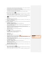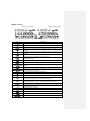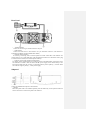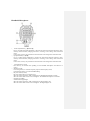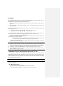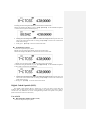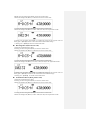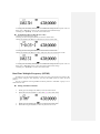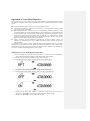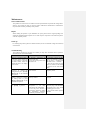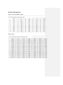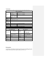
1
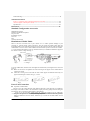
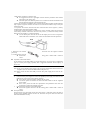
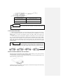
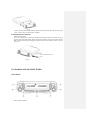
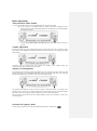
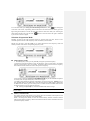
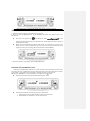
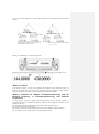
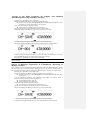
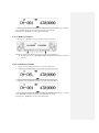
Operation Instructions of 9900 Vehicle-Mounted Walkie Talkie ©All rights reserved Quanzhou Baojie Electronics Co., Ltd. 1 Friendly Reminder: The purchase and use of this device is an acts of setting up and using a radio station, and must go through the procedures by laws for the approval of radio station setup and obtain a license for radio station. The use of this device shall conform to the items approved by the license thereof. Any radio station or radio interference business without authorization, any operation thereof exceeding the scope of license and other acts violating the radio administration regulations shall be punished by the radio administrative institution. Serous conducts may violate Article 288 of the Criminal Law or Article 28 of the Public Security Administration Punishment Law, and a criminal punishment of fixed term imprisonment of not more than three 致谢 years, criminal detention or public surveillance and additional or exclusive fine or administration punishment of detention by public security organ may be imposed. 感谢讲机亦不例外。本公司相信本产品将同时满足您对语音和资料通讯的苛刻要求。 Acknowledgement Thank you for purchasing this walkie talkie. We have been dedicated to providing novel and fine radio products, including this walkie talkie. We believe this product will satisfy your strict requirements on both voice and data communication. Important Notice: Warning Explosive atmosphere (gas, dust, smog, etc.) Please turn off the walkie talkie in oil filling or when your vehicle stops at a filling station. If your walkie talkie is installed in the trunk, please not place the reserve fuel tank in the trunk. Damage from radio signal transmission When there is any person around the antenna fittings or touching the antenna, please do not operate your walkie talkie so as to avoid possible damage or human body injure due to radio frequency. Gunpowder and detonator The operation of the talkie walkie within 150m (500ft) to gunpowder and detonator may lead to explosion. In the region of explosion or the region with sign “Close dual-way radio”, please turn off your walkie talkie. If your vehicle is used to transport gunpowder and detonator, be sure they are in the black sealed metal box with internal packing layer. Do not transmit signals when you put the gunpowder and detonator into or take out them from the metal box. 金属箱内运输。将火药、雷管放入或从包装箱中取出时,不要发射讯号。 Attentions Please observe the following instructions to avoid fire, human injure or device damage. Do not try to set the walkie talkie during driving, which may lead to dangerous consequence. Do not transmit at a large power for a long time. Otherwise, the walkie talkie may become too hot so that its service life will be shortened. Unless otherwise specified in this manual or instructions, do not dismantle or retrofit the walkie talkie for any reason. 2 Do not expose the walkie talkie to blazing sun for quite a long time or put it near a heating appliance. Do not put the walkie talkie at places where there is too much dust, damp or water splash or on instable surface. If any abnormal smell or fume is found from the walkie talkie, immediately turn off its power and contact the local distributer. Using a walkie talkie in driving may violate traffic laws. Please inquire or consult the local transportation administration body about it and observe the local traffic laws. Do not use options not designated by this company. Attention The walkie talkie is designed to use 13.8V DC (±15%) power supply! Never use 24V batteries. Prior to installing it on the vehicle, please inspect the battery polarity and voltage of the vehicle. Only use the DC power line attached or designated by this company. Never insert a metal object into the cooling fan. Warning Do not cut down or remove the fuse holder of the DC wire. Wrong connection may lead to fume and further fire. To ensure passengers’ safety, please use the attached installation support and screw set in the installation of the walkie talkie and be sure that it will not slip out in case of vehicle collision. Lack of proper protection or isolation of various electronic devices in the vehicle from radio RF energy during the transmission of the walkie talkie may lead to their damage. For example, electronic fuel injector, anti-slide brake and navigation control system are easy to be damaged. If your vehicle is furnished with such devices, please consult the vehicle distributor on whether it is necessary to protect them in transmission. 3 Table of Contents 批注 [u1]: 目录中的标红处的标题与 Preparation 正文处不符 Standard Configuration Accessories---------------------------------------------------------------------6 Installation of Walkie Talkie------------------------------------------------------------------------------6 Power Line Connection -----------------------------------------------------------------------------------6 Connection of Antenna------------------------------------------------------------------------------------8 Removal and Installation of Front Panel----------------------------------------------------------------8 Connection of Accessories--------------------------------------------------------------------------------9 Get Familiar with the Talkie Walkie Front Panel------------------------------------------------------------------------------------------------10 Display ----------------------------------------------------------------------------------------------------12 Screen------------------------------------------------------------------------------------------------------12 Rear Panel-------------------------------------------------------------------------------------------------13 Subpanel---------------------------------------------------------------------------------------------------13 Handheld Microphone-----------------------------------------------------------------------------------14 Basic Operations Turn On/Off the Talkie Walkie-----------------------------------------------------------------------15 Volume Adjustment------------------------------------------------------------------------------------15 Squelch Level Adjustment----------------------------------------------------------------------------15 Selection of Frequency Band-------------------------------------------------------------------------15 Selection of Operation Mode-------------------------------------------------------------------------16 Transmission--------------------------------------------------------------------------------------------17 Selection of Transmission Power---------------------------------------------------------------------17 Context Menu Mode Setting of Context Menus-----------------------------------------------------------------------------19 Context Menu Setting----------------------------------------------------------------------------------19 Operation via Repeater Setting of Repeater------------------------------------------------------------------------------------21 Selection of Pilot Frequency-------------------------------------------------------------------------23 Transmission of Pilot Frequency--------------------------------------------------------------------23 Reverse Frequency Function------------------------------------------------------------------------23 Memory Channel Memory Channels for Simplex Transmission/Receiving with the Identical Frequency or Transmission /Receiving with Different Frequencies? -----------------------------------------24 Storage of the Same Frequency for Simplex and Standard Transmission/Receiving in Memory Channel-------------------------------------------------------------------------------------25 Storage of Different Frequencies of Transmission /Receiving in Memory Channel------------------------------------------------------------------------------------------------25 4 Use of Memory Channel----------------------------------------------------------------------------26 Clear of Memory Channel--------------------------------------------------------------------------26 Scanning Scanning Mode---------------------------------------------------------------------------------------27 Turn on Scanning------------------------------------------------------------------------------------27 Continuous Tone Coded Squelch System (CTCSS) Use of CTCSS------------------------------------------------------------------------------------------27 Digital Coded Squelch (DCS) Use of DCS--------------------------------------------------------------------------------------------28 Dual Tone Multiple Frequency (DTMF) Setting of DTMF code block--------------------------------------------------------------------------30 Selection of receiving DTMF code block------------------------------------------------------------31 Selection of squelch mode-----------------------------------------------------------------------------32 Selection of transmission of DTMF code block-----------------------------------------------------32 Selection of DTMF transmission mode---------------------------------------------------------------33 Selection of DTMF transmission time----------------------------------------------------------------34 FM Radio Use of FM radio-----------------------------------------------------------------------------------------35 Auxiliary Functions Power-on Information---------------------------------------------------------------------------------35 Key Locking--------------------------------------------------------------------------------------------35 Setting of Wide and Narrow Bands (W/NA)-------------------------------------------------------35 Setting of Voice Companding (COMP)-------------------------------------------------------------36 Setting of Voice Encryption (SRMR)---------------------------------------------------------------37 Setting of Frequency Step (STEP)-------------------------------------------------------------------37 Setting of Prompt Tone (BEEP)----------------------------------------------------------------------38 Setting of Backlight (LED)---------------------------------------------------------------------------38 Setting of Busy Channel Lock (BCL)---------------------------------------------------------------38 Setting of Transmission Time-out Timer (TOT)---------------------------------------------------39 Restoration of Factory Setting (RESET)------------------------------------------------------------40 Operation of AM Aircraft Frequency Band Setting Steps for AM Aircraft Frequency Band----------------------------------------------------41 Operation of Cross-Band Repeater Setting Steps for Cross-Band Repeater Operation-------------------------------------------------42 Maintenance General Information-----------------------------------------------------------------------------------43 Repair----------------------------------------------------------------------------------------------------43 Clean-up-------------------------------------------------------------------------------------------------43 5 Troubleshooting----------------------------------------------------------------------------------------43 Technical Parameters Annex 1: Continuous Tone Coded Squelch System (CTCSS)----------------------------------44 Annex 2: Digital Coded Squelch (DCS)-----------------------------------------------------------44 Specifications------------------------------------------------------------------------------------------45 Declaration---------------------------------------------------------------------------------45 Standard Configuration Accessories Handheld microphone Holder for handheld microphone DC power line Installation support Screw set Fuse Operation Instructions Installation of Walkie Talkie Select a safe and convenient site in your vehicle so as to reduce possible damage to your passenger or yourself during vehicle movement. You may install the walkie talkie blow the instrument panel in front of the front passenger seats so that your knee and legs will not collide the walkie talkie. It’s best to select a well ventilated site where direct exposure to sun can be avoided. 1. Use the attached self-tapping screws (4) and flat washers (4) to install the installation support in the vehicle as shown in Fig. 1 and Fig. 2. Vehicle body Washer M5 Cone screw Installation support Fig. 1 Fig.2 Fig. 3 2. Fix the walkie talkie, and then insert and tighten the attached the (4) hexagonal screws as shown in Fig. 3. Make sure all screws are tightened to avoid loosening of the support or the walkie talkie in vibration of vehicle. Utilize the 3 screw grooves at the side rear side of each support to install the main body at a proper inclined angle as shown in Fig., 4, 5 and 6. Fig. 4 Fig. 5 Fig. 6 Power Line Connection Operation of talkie walkie Be sure to use 12V vehicle batteries with sufficient electricity. If the electricity is insufficient, the display screen will turn dark or the transmission output power may greatly decrease during the transmission. Never connect the talkie walkie to 24V batteries. Note: If you use the talkie walkie when the vehicle-use batteries are not sufficiently charged or the generator is off, battery discharge may lead to insufficient electricity quantity, making it difficult to start the vehicle. Therefore, try to avoid use the talkie walkie in such situation. 1. Use the DC power line attached with the talkie walkie to connect the talkie walkie with the 6 vehicle battery terminal in a shortest route. It is suggested not to use a cigar lighter socket as much as possible as some of them may lead to great voltage drop. The whole power line must be packed so as to isolate it from heat and moisture and from the generator ignition system/connection line. 2. When the power line is installed in place, wind the fuse holder with heat-resistant adhesive tape to protect it against moisture. It’s better to use heat-resistant adhesive tape to wrap the whole power line. 3. To prevent short-circuit, disconnect the other connection lines at the negative (-) battery terminal before connecting the talkie walkie. 4. Please first confirm the polarity of connection is correct, and then connect the power line to the battery terminal. Connect the red wire to the positive (+) terminal of battery and the black wire to the negative (-) terminal of battery. Use the whole power line and do not cut the surplus part even if it is longer than required. Be sure to remember: never remove the fuse holder from the power line. Red Black 5. Reconnect all connection lines that have been disconnected from the negative terminal previously. 6. Connect the DC power line to the walkie talkie. Press them together with force till the locating plate is locked with a sound of “click”. Operation of fixed radio station If you intend to use the talkie walkie as a fixed radio station, you need to buy a independent type of 13.8 DC power supply separately with a suggested continuous current capacity of above 12A. Note: Do not connect this DC power supply to the AC power socket before all connections are completed. (Do not connect the talkie walkie with power on.) Please connect all lines and finally insert the DC power supply device into the AC socket. 1. 2. Be sure the talkie walkie and the DC power supply are off. Connect the DC power supply line to the DC regulated power supply and make sure the polarities are correct (red: positive, black: negative). Never directly connect the talkie walkie to the AC socket. Use the DC power line attached to connect the talkie walkie to the DC regulated power supply. Never use a power line with the specification and parameters lower than the original one to replace the original power line. 3. Connect the DC power line to the talkie walkie. Press them together with force till the locating plate is locked with a sound of “click”. Fuse replacement If the fuse burns out, please find out the cause and remove it. After that, replace the fuse. If the fuse newly installed continues to burn out, disconnect the power line and contact the authorized distributor for help. 7 Location of fuse Rated current of fuse talkie walkie 15A Attached DC power line 20A Attention Use the fuse of designated type and rated value. Otherwise, the talkie walkie may be damaged at your own risk. Connection of Antenna Before using the talkie walkie, you must install a high efficiency and fine tuned antenna. Successful installation depends on the correct antenna type and installation. If a proper antenna system is selected and installed correctly, the talkie walkie will achieve best performance. Use an antenna with a characteristic impedance of 50Ω and a low loss coaxial feeder also with 50Ω characteristic impedance to match the input impedance of the talkie walkie. Using a feeder with an impedance of other than 50Ω to connect the antenna with the talkie walkie will reduce the performance of the antenna system, may cause interference to the nearby radio and TV receivers, radio receivers and other electronic devices and even damage the talkie walkie. Attention Without the connection with antenna or other matched load, it is prohibited to use Att the talkie walkie to transmit. Otherwise, the talkie walkie will be damaged. Be sure to connect the antenna to the talkie walkie before transmission, and only when the connection is confirmed can the transmission be made. All fixed radio stations must be furnished with a lightning arrester to reduce the risk of the damage of talkie walkie by fire or electric shock. The location and fixed mode of the antenna on the vehicle are shown as follows: Removal and Installation of Front Panel In the light of the location/mode of the installation of talkie walkie, you may remove the front panel and install it to a proper site with the extension line. 1. At the left side of the front panel, push the release bolts of the front panel directly to the left rear direction as shown in Fig. 8. Fig. 8 2. Slide the front panel in parallel to left and pull it out forward and away from the main body of the talkie walkie as shown in Fig. 9. 8 Fig. 9 3. Move the front panel translationally from left to right till the front panel fits the body and a “click” is heard. Thus, the front panel is installed. Connection of Accessories Handheld microphone For voice communication, connect the handheld microphone attached to the MIC socket on the right side of the talkie walkie. Please align the RJ12 plastic spring piece upward with the MIC socket till the locking-locating plate is locked in place with a sound of “click” as shown in Fig. 10. MIC socket Plug of handheld microphone Fig.10 Get Familiar with the Talkie Walkie Front Panel ① Left tuning knob (DIAL) 9 Rotate this knob to select the left band operation frequency or memory channel, change the scanning direction and select functional menu and parameters. Press this knob shortly to switch the left band as the main band. If the left band is set as the main band, press this knob shortly will enter the first level and second level of the setting status of functional menu. In the functional menu setting status, press this knob shortly to confirm the setting. ② Left volume/muting knob (VOL SQL) The center VOL (volume) control knob is used to tune the speaker volume in receiving by left band. Turn it clockwise to increase the volume. The outer SQL (squelch) control knob is used to eliminate the background noise in receiving by left band. Turn it clockwise to the extent that the noise just disappears (the on the screen disappears) so as to improve the sensitivity of weak signal. ③ Left keys 【REV】for frequency reverse selection Shortly press 【REV 】 . If the left band starts the frequency reverse function, the transmission-receiving frequency will reverse. 【H/L】for power adjustment Shortly press 【H/L】 ,the left band transmission power can be switched between high power (High) and low power (Low). 【CMP】for starting companding Shortly press 【CMP】to open the left band companding function. 【MHz】for MHz and Mb adjustment Shortly press【MHz】and the Mb will flicker. Turn DIAL to adjust the Mb frequency and press DIAL shortly to confirm it. 【V/M】for switching between VFO frequency mode and memory channel mode Shortly press this key to switch the left band frequency control mode between VFO frequency mode and memory channel mode. 【SCN】for scanning Shortly press this key to activate the scanning of left band. 【EXIT】for return/exit ④ 【FM/ 】for starting radio receiver/locking keypad Shortly press this key to enter/exit the FM receiver mode. Press this key for long to start the keypad lock. ⑤ Right side keys 【EXIT】for return/exit 【SCN】for scanning Shortly press this key to activate the scanning of left band. 【V/M】for switching between VFO frequency mode and memory channel mode Shortly press this key to switch the right band frequency control mode between VFO frequency mode and memory channel mode. 【MHz】for MHz and Mb adjustment Shortly press【MHz】and the Mb will flicker. Turn DIAL to adjust the Mb frequency and press DIAL shortly to confirm it. 【CMP】for starting companding Shortly press 【CMP】to open the right band companding function 【H/L】for power adjustment Shortly press 【H/L】 and the right band transmission power can be switched between high power (High) and low power (Low). 【REV】for frequency reverse selection Shortly press 【REV】. If the right band starts the frequency reverse function, the transmission-receiving frequency will reverse. ⑥ Right volume/muting knob (VOL SQL) The center VOL (volume) control knob is used to tune the speaker volume in receiving by right band. Turn it clockwise to increase the volume. The outer SQL (squelch) control knob is used to eliminate the background noise in 10 批注 [微软用户2]: 短按此键激活左 段扫描 不是右段吗? receiving by right band. Turn it clockwise to the extent that the noise just disappears (the on the screen disappears) so as to improve the sensitivity of weak signal. ⑦ Right tuning knob (DIAL) Rotate this knob to select the right band operation frequency or memory channel, change the scanning direction and select functional menu and parameters. Press this knob shortly to switch the right band as the main band. If the right band is set as the main band, press this knob shortly will enter the first level and second level of the setting status of functional menu. In the functional menu setting status, press this knob shortly to confirm the setting. 11 Display Screen <Left Frequency Band> Icon <Right Frequency Band> Description Displays the number of memory channel and context menu. Appears when the frequency reverse function is enabled. No definition for this device Appears when the transmission difference frequency offset is set as negative. Appears when the transmission difference frequency offset is set as positive. Appears when transmission of CTCSS (Continuous Tone Coded Squelch System) is enabled in transmission status. Appears when receiving of CTCSS (Continuous Tone Coded Squelch System) is enabled. Displays the transmission status. Displays that the current frequency band is the main one. Displays the operation frequency, name of memory channel and context menu. Appears in busy signal receiving Displays the signal strength in receiving while displaying the power level selected in transmission. Appears when the scrambling function is on. Appears when the companding function is on. Appears in narrow band mode. Appears when the DCS function is on. (When the transmission DCS is started, it will appear only in the transmission status.) Appears when the AM aircraft frequency band is started and the left or right band frequency is in the scope of aircraft frequency band. No definition for this device Appears when low transmission power is used. (No icon display for high transmission power). No definition for this device No definition for this device Appears when the keypad is locked. Appears when entering the function menu mode. No definition for this device 12 Rear Panel ① Antenna interface Connect N-connector type external antenna to this port. ② Data interface Connect the TNS device to this interface via 6-pin mini DIN connector. (This function is temporally unavailable and for B model talkie walkie). ③ External speaker interface If necessary, connecting with an external speaker for better sound effect. This interface can connect with a 2-core 3.5mm audio plug. The matched load resistance is 8 ohm. When such a plug is inserted into the interface, the internal speaker will stop. ④ 13.8V DC power supply interface and fuse block It is the DC power supply interface for supplying power to the talkie walkie. Use the DC power line attached to connect it with the above 12A DC power supply of the vehicle battery or the base station. Make sure the red wire is connected with the positive polarity (+) and the black wire with the negative polarity (-) of the power supply. Subpanel ① MIC Connect the handheld microphone to this interface. ② PANEL When this panel needs to be installed separately from the main body, use the optional extension line for connection to connect the panel to this interface. 13 Handheld Microphone ① Down adjustment key (【DOWN】) Press it to make downward adjustment or decrease the main band operation frequency value, memory channel number (changing direction in scanning) or the setting value of function menu. In most cases, this key can perform the same functions as the tuning knob of the main band. ② Up adjustment key (【UP】) Use it to make upward adjustment or increase the main band operation frequency value, memory channel number (changing direction in scanning) or the setting value of function menu. In most cases, this key can perform the same functions as the tuning knob of the main band. ③ Transmission key (PTT) Press this key to transmit when speaking via the handheld microphone and release it to receive. ④ Numeric keypad In receiving status, it is used for frequency input in VFO frequency mode; In transmission status, it is used for DTMF dialing. ⑤ Key lock switch (LOCK) Key lock switch (all keys except PTT key) Move the switch up and the “OFF” will appear. The handheld microphone is locked. Move the switch down and the “ON” will appear. The handheld microphone is unlocked. ⑥ for lighting (LAMP) Switch for the keypad light. Move the switch up and the “OFF” will appear. The keypad light is off. Move the switch down and the “ON” will appear. The keypad light is on. 14 Basic Operations Turn On/Off the Talkie Walkie 1. To turn on the talkie walkie, press the right band (VOL) knob for 2 seconds. When you turn on the talkie walkie, the startup information will appear on the display screen for 2 seconds and the display screen will return to the normal display of operation frequency. 2. To turn off the talkie walkie, once again press the right band (VOL) knob for 2 seconds. Volume Adjustment The left band and right band volume adjustments are separate from each other. The left volume knob (VOL) is for adjusting the left band volume and the right (VOL) is for adjusting the right band volume. Clockwise turn the volume knob will increase the volume of the selected band and counterclockwise turn it will decrease the volume. Squelch Level Adjustment The left band and right band squelch adjustments are also separate from each other. The left squelch knob (SQL) is for adjusting the left band squelch level and the right (SQL) is for adjusting the right band squelch level as shown by the arrow in the figure below. The squelch level function is used to close the speaker volume when there is no signal. If the squelch level is correctly set, you will hear sound only when actually receiving signals. The higher the squelch level, the stronger the signal strength for you to hear the sound will be. Turn the (SQL) control bottom for the selected frequency band to just eliminate or reduce the surrounding noise. Selection of Frequency Band In dual-receiving operation, the main band (transmissible band) is indicated by . 15 To set the main band, just shortly press the left tuning knob (DIAL). The icon will appear on the left of the screen, representing that the left band is the main band now. Shortly press the right tuning knob (DIAL) to switch the right band into the main band. With your switching the main band from left to the right, the icon by the arrow in the above figure. will move from the left to the right as indicated Selection of Operation Mode Similarly, the left and the right operation modes are separate from each other. There are two selectable operation modes: VFO frequency mode and memory channel mode. Shortly press the left or right 【V/M】 key to switch between the VFO frequency mode and memory channel mode for the corresponding frequency band. VFO frequency mode 1、 In VFO frequency mode, you may manually change the operation frequency. 1. Rotate the tuning knob (DIAL) to tune the frequency of the current band in accordance with the preset frequency step conveniently. Clockwise rotation will increase the frequency and counterclockwise rotation can reduce the operation frequency. 2. You may also adjust the frequency by 【UP】/ 【DOWN】 key on the handheld microphone or directly enter the required frequency value via its keypad. 3. To make a large amount of frequency adjustment, you may shortly press 【MHz】 key to enter the MHz mode. In the MHz mode, rotate the tuning knob to make frequency adjustment at 1MHz interval. Shortly press the tuning knob to confirm and exit the MHz mode and use the general frequency step to adjust the frequency. Shortly press【EXIT】key will exit the MHz mode without storage. Note: The product offers the frequency steps of 2.5K, 5K, 6.25K, 10K, 12.5K, 25K and 50K for your choice. Memory channel mode The memory channel mode enables you to quickly select the commonly used frequencies and related data stored in the memory of the talkie walkie. Rotate the tuning knob (DIAL) to select the needed memory channel. Clockwise rotation will lead to the higher frequency channel and counterclockwise rotation will lead to the lower operation frequency channel. 16 Note: Refer to No. 24 page for the details of the setting of memory channel. Transmission 1. Select the required frequency band and frequency/channel. 2. Press and hold the【PTT】switch of the handheld microphone and speak toward it for transmission. The screen will display the selected transmission frequency band. The RF power meter displays the relative power of the transmission output. Speak toward the handheld microphone with normal voice and keep it 5cm from your mouth. Too near to the microphone or too loud a voice will increase the distortion of the signals received by the receiving radio and reduce their understandability. and RF power meter of the 3. After the completion of speaking, release the【PTT】switch. Selection of Transmission Power Under good communication conditions, it is better to select a lower transmission power, which may reduce the risk of interference with the other frequencies at the same band. When a battery power supply is used, make sure if recharging is needed to prepare for long time use. Shortly press 【H/L】key to select high power (no display) or low ( ) power. You may set the left and right bands with different power levels. You may also adjust the transmission power by context menu. 1. Shortly press the tuning knob (DIAL) to enter the context menu. 2. Rotate (DIAL) to select Item 11 on the context menu. 17 3. 4. Shortly press the tuning knob (DIAL)to set the current context menu. Rotate the tuning knob (DIAL) to select “HIGH (high power) or LOW (low power )”. 5. Shortly press the tuning knob (DIAL) to confirm the storage of the required value. Or shortly press 【EXIT】 to return to the context menu mode without storage. shortly press 【EXIT】 to exit the context menu mode. 6. Note: If the talkie walkie is too hot due to the high temperature in surrounding environment temperature or continuous transmission, the protection circuit may automatically start the protection function to reduce the transmission output power. 18 Context Menu Mode Many function of this walkie talkie are selected or set via the context menu (other than actual control bottom). When you become familiar with the context menu system, you will like them for the various functional conveniences they provide. Setting of Context Menus 1. Shortly press the tuning knob (DIAL) and you may set the operation of context menu. The name and number of the context menu will appear on the screen. 2. Rotate the tuning knob (DIAL) to select the required context menu. 3. Shortly press the tuning knob (DIAL) to set the current context menu. 4. Rotate the tuning knob (DIAL) to select the required value for the selected context menu. 5. Shortly press the tuning knob (DIAL) to set the required value. 6. Repeat Steps 2~5 to set more context menus. Shortly press 【EXIT】 to cancel the setting of context menu and return to the interface of selecting the context menu. Once again shortly press 【EXIT】to exit the context menu mode. Context Menu Setting No. of context menu 01 02 03 04 05 06 07 Display Description Set value Preset Setting of CTCSS for OFF: closed OFF receiving 67.0~254.1Hz Setting of the positive code of OFF: closed R-DCS-N OFF DCS for receiving D023N~D754N Setting of the reverse code of OFF: closed R-DCS-I OFF DCS for receiving D023I~D754I Setting of DTMF for OFF: closed R-DTMF OFF receiving DTMF1-8 QT: quiet talk SP-SQUELC QT+DTMF: quiet talk Squelch mode QT H +dual tone multiple frequency Setting of continuous tone OFF: closed T-CTCSS coded squelch system for OFF 67.0~254.1Hz transmission Setting of the positive code of OFF: closed T-DCS-N digital coded system DCS for OFF D023N~D754N transmission R-CTCSS Reference page 27 28 29 31 31 28 29 19 08 T-DCS-I 09 T-DTMF 10 PTT-ID 11 POWER 12 W/NA 13 COMP 14 SRMR 15 SFT 16 OFFSET 17 STEP 18 CH-SAVE 19 CH-DEL 20 BEEP 21 LED 22 BCL 23 TOT 24 TONE 25 DTMF-TM 26 RPT 27 AM-SW 28 29 DTMF RESET Setting of the reverse code of OFF: closed digital coded system DCS for OFF D023I~D754I transmission Setting of dual tone multiple OFF: closed OFF frequency for transmission DTMF1-8 OFF: closed BOT: press to transmit the code EOT: release to Transmission of ID code OFF transmit the code BOTH: press or release to transmit the code HIGH: high power Setting of transmission power HIGH LOW: lower power Selection of broad or narrow WIDE: broad band WIDE band NARR: narrow band OFF : closed Voice companding OFF ON: open OFF :closed Voice encryption OFF ON: open OFF: closed Frequency offset direction (+): positive offset OFF (-): negative offset Frequency offset 00.0000-90.0000MHz 00.0000 2.50K, 5.00K, 6.25K, Frequency step 10.00K, 12.50K, 25K, 5.00K 50.00K 128 signal channels on Channel storage either of the left and right CH-001 bands 128 signal channels on Channel deletion either of the left and right CH-001 bands OFF: closed Prompt tone ON ON: open OFF: closed LED1: red LED2: blue LED3: purple Backlight LED4 LED4: green LED5: yellow LED6: light blue LED7: white OFF: closed Busy channel lock OFF ON: open OFF: closed Time out time OFF 30S~600S(20 shifts) 1000Hz 1450Hz Pilot carrier frequency 1000HZ 1750Hz 2100Hz 50MS 100MS DTMF transmission time 100MS 150MS 200MS OFF: closed Start of cross-band repeater OFF ON: open OFF: closed Start of AM aircraft band OFF ON: open DTMF group 8 groups ------Reset RST-NO: do not reset RES-NO 30 32 33 17 35 36 36 21 22 37 24 26 37 38 38 38 23 34 42 41 30 40 20 RST-YES: reset Operation via Repeater The repeaters are generally installed and maintained by radio club or sometimes, in cooperation with local communication system enterprises. Compared with simplex communication, you can generally transmit over a farther distance via the repeater. Repeaters are generally installed at mountain top or other higher position and can operate at ERP (effective transmission power) higher than that by general radio stations. High-placed installation in combination with high ERP can achieve communication over a farther distance. Setting of Repeater Most of the repeaters use receiving/transmission frequency pairs with standard or non-standard frequency offset (different frequencies for transmission and receiving). Moreover, some repeaters can be utilized only when receiving voice frequency from a talkie walkie. For details, please consult the owner of the local repeater system. 1. Selection of frequency offset direction The offset direction can enable your transmission frequency to be higher (+) or lower (-) than the receiving frequency. 1. Shortly press left or right tuning knob (DIAL) to select the required frequency band. 2. Shortly press the tuning knob (DIAL) to enter the context menu. 3. Rotate the tuning knob (DIAL) and select Item 15 of the context menu as shown in the figure. 4. Shortly press the tuning knob (DIAL) to set the current context menu. 5. Rotate the tuning knob (DIAL) and select “OFF (turn-off), (+) positive offset or (-) negative offset”. 21 6. Shortly press the tuning knob (DIAL) to confirm the storage of required value. According to the site of the operation frequency in the band, when the offset is valid, these icons will be displayed on the screen. Positive frequency offset (+) Negative frequency offset (-) Or shortly press 【EXIT】to return to the context menu mode without storage. 7. Shortly press 【EXIT】to exit the context menu mode. If the transmission frequency after offset exceeds the permissible scope, the transmission will be prohibited. Adopt one of the following methods to adjust the transmission frequency to be within the band restriction scope. Increase or decrease the receiving frequency within the band. Change the offset direction 2. Selection of offset frequency The offset frequency is the transmission frequency value deviated from the receiving frequency. 1. Shortly press left or right tuning knob (DIAL) to select the required frequency band. 2. Shortly press the tuning knob (DIAL) to enter the context menu. 3. Rotate the tuning knob (DIAL) and select Item 16 of the context menu as shown in the figure. 4. Shortly press the tuning knob (DIAL) to set the current context menu. 5. Directly enter the required offset frequency via the keypad of handheld microphone, which will be automatically saved. 22 6. Shortly press the tuning knob (DIAL) to return to the context menu mode. 7. Shortly press 【EXIT】to exit the context menu mode. Note: The selectable offset frequency values are from 00.000MHz to 90.000MHz. Selection of Pilot Frequency This function is used to wake up the repeater in sleep status. Such repeater needs to be awaked up by pilot frequency of certain strength. Generally, when the repeater is waked up, it is not necessary to transmit the pilot frequency again. 1. Shortly press the tuning knob (DIAL) to enter the context menu. 2. Rotate the tuning knob (DIAL) and select Item 24 of the context menu. 3. Shortly press the tuning knob (DIAL) to set the current context menu. 4. Rotate the tuning knob (DIAL) and select “1000Hz,1450Hz,1750Hz or 2100Hz”. 5.Shortly press the tuning knob (DIAL) to confirm the storage of required value. Or shortly press 【EXIT】to return to the context menu mode without storage. 6. Shortly press 【EXIT】to exit the context menu mode. Transmission of Pilot Frequency Press the 【PTT】key of the handheld microphone to transmit the pilot frequency and then press the 【UP】key to sent the pilot frequency. Reverse Frequency Function After setting the separate receiving and transmission frequencies, use the reverse frequency function to exchange them so as to enable you to manually inspect the strength of the signals received from another radio while using the repeater. If the signal of such radio is very strong, 23 move to the simplex frequency to continue the connection and suspend the connection with the repeater. A B A Press REV. A’s transmission frequency is 138.750 and B’s receiving frequency is 136.025. Therefore, the communication cannot be made. B Communication is normal without repeater. Shortly press 【REV】 to switch the frequencies. When the reverse frequency function is on, the symbol “ ” will appear on the display screen. Memory Channel In the memory channel, you may store frequently used frequencies and related data. Then, you need not reset them every time and you may quickly call the set channel via simple operation. There are 128 memory channels on either of the left and right bands available. Memory Channels for Simplex Transmission/Receiving with the Identical Frequency or Transmission/Receiving with Different Frequencies? Use any memory channel for simplex transmission/receiving with the identical frequency or transmission/receiving with different frequencies. Select any of the application methods for each channel as required. The channel for simplex transmission/receiving with the same frequency allows: the operation of simplex frequency. The memory channel for simplex transmission/receiving with different frequencies allows: the operation of the repeater with non-standard frequency offset. 24 Storage of the Same Frequency for Simplex and Standard Transmission/Receiving in Memory Channel 1. Shortly press 【V/M】 to enter VFO mode. 2. Rotate the tuning knob (DIAL) to select the required frequency. Besides, you may press 【UP】/【DOWN】 on the handheld microphone to select the frequency or enter the frequency via its keypad. 3. Any other data needed by frequency setting. Voice frequency, CTCSS frequency, DCS code, etc. 4. Shortly press the tuning knob (DIAL) to enter the context menu. 5. Rotate the tuning knob (DIAL) to select Item 18 on the context menu. 6. Shortly press the tuning knob (DIAL) to set the current context menu. 7. Rotate the tuning knob (DIAL) and select the required memory channel number. 8. Shortly press the tuning knob (DIAL) to confirm the storage of required value. Or shortly press 【EXIT】to return to the context menu mode without storage. 9. Shortly press 【EXIT】to exit the context menu mode. Note: The storage of receiving and transmission will cover the original stored information in the memory channel. Storage of Different Frequencies of Transmission /Receiving in Memory Channel Some repeaters use the transmission/receiving frequencies with non-standard frequency offsets. For their storage, two separate frequencies should be stored in the memory channel. Then, you may operate these repeaters without changing the offset frequencies stored in the context menu. 1. Shortly press 【V/M】 to enter VFO mode. 2. Rotate the tuning knob (DIAL) to select the required receiving frequency. Besides, you may press 【UP】/【DOWN】 on the handheld microphone to select the frequency. 3. Set the transmission frequency with a difference value higher than (positive offset) or lower than (negative offset) the receiving frequency. Set the offset direction. (Page 21 ) Set the offset frequency. (Page 22) 4. Any other data needed by frequency setting: voice frequency, CTCSS frequency, DCS code, etc. 5.Shortly press the tuning knob (DIAL) to enter the context menu. 6. Rotate the tuning knob (DIAL) to select Item 18 on the context menu. 7. Shortly press the tuning knob (DIAL) to set the current context menu. 8. Rotate the tuning knob (DIAL) and select the required memory channel number. 25 9. Shortly press the tuning knob (DIAL) to confirm the storage of required value. Or shortly press 【EXIT】to return to the context menu mode without storage. 10. Shortly press 【EXIT】to exit the context menu mode. Use of Memory Channel 1. Shortly press 【V/M】 to enter the mode of memory channel use. 2. Rotate the tuning knob (DIAL) to select the required receiving frequency. Besides, you may press 【UP】【 / DOWN】on the handheld microphone to select the channel. Clear of Memory Channel 1. 2. Shortly press the tuning knob (DIAL) to enter the context menu. Rotate the tuning knob (DIAL) to select Item 19 on the context menu 3. Shortly press the tuning knob (DIAL) to set the current context menu. 4. Rotate the tuning knob (DIAL) and select the required channel number. 5. Shortly press the tuning knob (DIAL) to confirm the deletion of this channel. Or shortly press 【EXIT】to return to the context menu mode without storage. 6. Shortly press 【EXIT】to exit the context menu mode. 26 Scanning The “scanning” function is used to monitor the required frequency. Getting familiar with the scanning function will greatly improve your operation efficiency. This talkie walkie provides the following scanning modes. 1. VFO scanning: In the VFO frequency mode, it will scan the whole frequency band with step frequency. 2. Channel scanning: In the memory channel mode, it will scan all channels stored in the memory channels The scanning may be made simultaneously at both the main and secondary frequency bands. Start the scanning as follows: 1. Shortly press the left or right 【V/M】 to select the scanning mode. 2. Shortly press the left or right 【SCN】 to start scanning. When a matched signal is detected, the talkie walkie will stay at the busy frequency or memory channel till 8 seconds after the signal disappears and then continue to scan. When the talkie walkie is in the scanning status, 1. Shortly press the tuning knob (DIAL) to stop scanning and keep the talkie walkie at the current frequency or memory channel. You may also press the 【PTT】key on the handheld microphone to stop scanning and make conversation at the current frequency or memory channel. 2. Shortly press 【EXIT】to exit the scanning status and return to the frequency or memory channel used before the scanning. Note: When the CTCSS or DCS is activated, the talkie walkie will stay at the busy frequency and decode the CTCSS voice frequency or DCS codes. If the voice frequency or the codes are matched, the squelch will be stopped. Otherwise, the talkie walkie will recover the scanning. In scanning, you may rotate 【DIAL】 to change the scanning frequency direction. Adjust the squelch level before using the “scanning” function. Too low a squelch level may lead to immediate stop of “scanning”. Continuous Tone Coded Squelch System (CTCSS) Sometimes, you may need to listen to only the call from a certain person. Continuous Tone Coded Squelch System (CTCSS) can make you ignore (cannot hear) the calls from other persons using the same frequency. To use this function, please select the CTCSS voice frequency selected by other persons of your group. CTCSS voice frequency cannot be heard. (Refer to the CTCSS Voice Frequency List in the annex.) Note: CTCSS does not guarantee your conversation privacy. It only makes you avoid irrelative calls. Use of CTCSS Receiving CTCSS 1. Select the required frequency band. 2. Shortly press the tuning knob (DIAL) to enter the context menu. 3. Rotate the tuning knob (DIAL) to select Item 01 on the context menu 27 4. Shortly press the tuning knob (DIAL) to set the current context menu. 5. Rotate the tuning knob (DIAL) or press 【UP】/【DOWN】 on the handheld microphone to select OFF or required CTCSS frequency. 6. Shortly press the tuning knob (DIAL) to confirm the storage of the required value and return to the context menu mode. Or shortly press【EXIT】 to return to the context menu mode without storage. 7. shortly press 【EXIT】 to exit the context menu mode. Transmission CTCSS 1. Select the required frequency band. 2.Shortly press the tuning knob (DIAL) to enter the context menu. 3. Rotate the tuning knob (DIAL) to select Item 06 on the context menu 4. Shortly press the tuning knob (DIAL) to set the current context menu. 5. Rotate the tuning knob (DIAL) or press 【UP】/【DOWN】 on the handheld microphone to select OFF or required CTCSS frequency 6. Shortly press the tuning knob (DIAL) to confirm the storage of the required value and return to the context menu mode. Or shortly press【EXIT】 to return to the context menu mode without storage. 7. shortly press 【EXIT】 to exit the context menu mode Digital Coded Squelch (DCS) The Digital Coded Squelch (DCS) is another way to make you ignore (cannot hear) the irrelative calls of other persons using the same frequency. Its function is the same as that of CTCSS. The only difference lies in the coding/decoding method and optional code quantity. (Refer to the DCS Code List in the annex.) Use of DCS Receiving DCS-N(DCS positive code) 1. Select the required frequency band. 28 2.Shortly press the tuning knob (DIAL) to enter the context menu. 3. Rotate the tuning knob (DIAL) to select Item 02 on the context menu. 4. Shortly press the tuning knob (DIAL) to set the current context menu. 5. Rotate the tuning knob (DIAL) to select “OFF (turn-off) or the required DCS code”. 6. Shortly press the tuning knob (DIAL) to confirm the storage of the required value .Or shortly press 【EXIT】to return to the context menu mode without storage. 7. Shortly press 【EXIT】to exit the context menu mode. Receiving DCS-I (DCS inverse code) 1. Select the required frequency band. 2. Shortly press the tuning knob (DIAL) to enter the context menu. 3. Rotate the tuning knob (DIAL) to select Item 03 on the context menu. 4. Shortly press the tuning knob (DIAL) to set the current context menu. 5. Rotate the tuning knob (DIAL) or to select “OFF (turn off) or the required DCS code”. 6. Shortly press the tuning knob (DIAL) to confirm the storage of the required value .Or shortly press 【EXIT】 to return to the context menu mode without storage. 7. Shortly press 【EXIT】 to exit the context menu mode. Transmission DCS-N (DCS positive code) 1. Select the required frequency band. 2. Shortly press the tuning knob (DIAL) to enter the context menu. 3. Rotate the tuning knob (DIAL) to select Item 07 on the context menu. 4. Shortly press the tuning knob (DIAL) to set the current context menu. 5. Rotate the tuning knob (DIAL) to select “OFF (turn-off) or the required DCS code”. 29 6. Shortly press the tuning knob (DIAL) to confirm the storage of the required value .Or shortly press 【EXIT】 to return to the context menu mode without storage. 7. Shortly press 【EXIT】 to exit the context menu mode. Transmission DCS-I (DCS inverse code) 1. Select the required frequency band. 2. Shortly press the tuning knob (DIAL) to enter the context menu. 3. Rotate the tuning knob (DIAL) to select Item 07 on the context menu. 4. Shortly press the tuning knob (DIAL) to set the current context menu. 5. Rotate the tuning knob (DIAL) to select “OFF (turn-off) or the required DCS code”. 6. Shortly press the tuning knob (DIAL) to confirm the storage of the required value .Or shortly press 【EXIT】to return to the context menu mode without storage. 7. Shortly press 【EXIT】to exit the context menu mode. Dual Tone Multiple Frequency (DTMF) In addition to CTCSS and DCS which can make you ignore (cannot hear) the irrelative calls of other persons using the same frequency, you may use DTMF system to realize the same purpose. You may set different receiving DTMF code block pertinent to individual or group so as to make selective calls. Setting of DTMF code block 1. 2. Shortly press the tuning knob (DIAL) to enter the context menu. Rotate the tuning knob (DIAL) to select Item 28 on the context menu. 3. 4. Shortly press the tuning knob (DIAL) to set the current context men. Rotate the tuning knob (DIAL) to select any block from “01-08”. 30 Use the keypad of the handheld microphone to enter “1, 2, 3, 4, 5, 6 and 7”. 5. 6. 7. 8. Press 【D】 on the keypad of the handheld microphone to delete the current block number. Shortly press the tuning knob (DIAL) to confirm the storage of the required value. Or rotate the tuning knob (DIAL) to enter the setting for the next block without the storage of the current value or shortly press 【EXIT】 to return to the context menu mode without storage Repeat Steps 3-6 and you may enter the required codes for other blocks. Shortly press 【EXIT】 to exit the context menu mode. Note: The left and right frequency bands will share only these 8 DTMF block numbers no matter you set such number at the left or the right band. Selection of receiving DTMF code block 1. 2. Shortly press the tuning knob (DIAL) to enter the context menu. Rotate the tuning knob (DIAL) to select Item 04 on the context menu. 3. 4. Shortly press the tuning knob (DIAL) to set the current context men. Rotate the tuning knob (DIAL) to select “OFF or DTMF1, DTMF2------DTMF8)”. 5. Shortly press the tuning knob (DIAL) to confirm the storage of the required value .Or shortly press 【EXIT】to return to the context menu mode without storage. Shortly press 【EXIT】to exit the context menu mode. 6. Selection of squelch mode To use the DTMF system, you need to select QT+DTMF for the squelch mode. Only the correct QT and DTMF frequencies are received can the speaker sound. 31 1. 2. Shortly press the tuning knob (DIAL) to enter the context menu. Rotate the tuning knob (DIAL) to select Item 05 on the context menu. 3. 4. Shortly press the tuning knob (DIAL) to set the current context men. Rotate the tuning knob (DIAL) to select “QT or QT+DTMF”. 5. Shortly press the tuning knob (DIAL) to confirm the storage of the required value .Or shortly press 【EXIT】to return to the context menu mode without storage. Shortly press 【EXIT】to exit the context menu mode. 6. Selection of transmission of DTMF code block 1. Shortly press the tuning knob (DIAL) to enter the context menu. 2. Rotate the tuning knob (DIAL) to select Item 09 on the context menu. 3. Shortly press the tuning knob (DIAL) to set the current context menu. 4. Rotate the tuning knob (DIAL) to select “OFF or DTMF1,DTMF2------DTMF8)”. 5. Shortly press the tuning knob (DIAL) to confirm the storage of the required value .Or shortly press 【EXIT】to return to the context menu mode without storage. 6. Shortly press 【EXIT】to exit the context menu mode. Selection of DTMF transmission mode 1. Manual call The keys on the keypad of the handheld microphone have the same function as DTMF keys: 12 keys on the keypad phone and 4 other keys (A, B, C and D). The manual call can transmit DTMF voice frequency by only two steps. 32 1. 2. Press the【PTT】key on the handheld microphone Press the keys in the keypad zone in sequence to transmit DTMF voice frequency. Frequency (Hz) 697 770 852 941 2. 1209 [1] [4] [7] [*] 1336 [2] [5] [8] [0] 1447 [3] [6] [9] [#] 1633 [A] [B] [C] [D] Auto code transmission There are three ways to realize the automatic transmission of DTMF frequency block. Press PTT to transmit code. Release PTT to transmit code Press or release PTT to transmit code. 1. Shortly press the tuning knob (DIAL) to enter the context menu. 2. Rotate the tuning knob (DIAL) to select Item 10 on the context menu。 3. Shortly press the tuning knob (DIAL) to set the current context menu. 4. Rotate the tuning knob (DIAL) to select “OFF, BOT (press for code transmission), EOT (release for code transmission) or BOTH (code transmission by either pressing or releasing)”. 5. Shortly press the tuning knob (DIAL) to confirm the storage of the required value .Or shortly press 【EXIT】to return to the context menu mode without storage. 6. Shortly press 【EXIT】to exit the context menu mode. 33 Selection of DTMF transmission time You may change the pause during the transmission of DTMF codes. 1. Shortly press the tuning knob (DIAL) to enter the context menu. 2. Rotate the tuning knob (DIAL) to select Item 25 on the context menu. 3. 4. Shortly press the tuning knob (DIAL) to set the current context menu. Shortly press the tuning knob (DIAL) to select “50MS, 100MS, 150MS or 200MS”. 5. Shortly press the tuning knob (DIAL) to confirm the storage of the required value .Or shortly press 【EXIT】to return to the context menu mode without storage. Shortly press 【EXIT】to exit the context menu mode. 6. 34 FM Radio Use of FM radio The product has built-in FM radio function. To turn on the FM radio as follows. 1. Shortly press 【FM/ 】to turn on the FM radio function. Rotate the tuning knob (DIAL) to make automatic search. Clockwise rotation is for upward search and counterclockwise rotation for downward search. The FM radio will work only on the main band. 2. Once again shortly press【FM/ 】to turn off the FM radio function. Auxiliary Functions Power-on Information Each time when you turn on the power supply of the talkie walkie, the related information will appear on the display screen for about 2 seconds. You may use your preferred information designed via write frequency software to replace the preset information. Key Locking The key locking function will disable most keys except 【VOL any wrong activation of a certain function. 1. To enable key locking function, just press【FM/ 2. Once again press【FM/ SQL】and 【PTT】 to avoid 】 for about 2 seconds. 】 for about 2 seconds to release the key locking. Setting of Wide and Narrow Bands Select lawful communication according to the regulation of each country. 1. Select the required frequency band. 2. Shortly press the tuning knob (DIAL) to enter the context menu. 3. Rotate the tuning knob (DIAL) to select Item 12 on the context menu. 35 4. 5. Shortly press the tuning knob (DIAL) to set the current context menu. Rotate the tuning knob (DIAL) to select “WIDE (wideband) or NARR (narrow band)”. 6. Shortly press the tuning knob (DIAL) to confirm the storage of the required value .Or shortly press 【EXIT】to return to the context menu mode without storage. Shortly press 【EXIT】to exit the context menu mode. 7. Voice Companding Function (for reducing noise and improving conversation clarity) This function can effectively reduce noise and improve conversation clarity, especially for long distance communication. You just need to press the left or right 【CMP】 to start the voice companding function of the corresponding frequency band. Once again shortly press this key and you will turn off this voice companding function. You may also enable the function via context menu. 1. Shortly press the tuning knob (DIAL) to enter the context menu. 2. Rotate the tuning knob (DIAL) to select Item 13 on the context menu。 3. 4. Shortly press the tuning knob (DIAL) to set the current context menu. Rotate the tuning knob (DIAL) to select “OFF (turn-off) or ON (turn-on)”. 36 5. 6. Shortly press the tuning knob (DIAL) to confirm the storage of the required value .Or shortly press 【EXIT】to return to the context menu mode without storage. Shortly press 【EXIT】to exit the context menu mode. Setting of Voice Encryption (against eavesdropping) This is a special voice processing mode, which can make a talkie walkie with the same frequency hear only scrambled voice, playing an effective role of confidentiality. 1. Shortly press the tuning knob (DIAL) to enter the context menu. 2. Rotate the tuning knob (DIAL) to select Item 14 on the context menu. 3. 4. Shortly press the tuning knob (DIAL) to set the current context menu. Rotate the tuning knob (DIAL) to select “OFF (turn-off ) or ON (turn-on)”. 5. Shortly press the tuning knob (DIAL) to confirm the storage of the required value .Or shortly press 【EXIT】to return to the context menu mode without storage. Shortly press 【EXIT】to exit the context menu mode. 6. Setting of Frequency Step Selecting a correct frequency step is of great importance to the selection of accurate frequency. 1. Shortly press the tuning knob (DIAL) to enter the context menu. 2. Rotate the tuning knob (DIAL) to select Item 17 on the context menu. 3. 4. Shortly press the tuning knob (DIAL) to set the current context menu. Rotate the tuning knob (DIAL) to select “2.50K, 5.00K, 6.25K, 10.00K, 12.50K, 25.00K or 50.00K”. 37 5. 6. Shortly press the tuning knob (DIAL) to confirm the storage of the required value .Or shortly press 【EXIT】to return to the context menu mode without storage. Shortly press 【EXIT】to exit the context menu mode. Setting of Prompt Tone The prompt tone is a function for confirming the operation prompt, operation error or fault status of the product. You can set to enable or disable the prompt tone function in the product. 1. Shortly press the tuning knob (DIAL) to enter the context menu. 2. Rotate the tuning knob (DIAL) to select Item 20 on the context menu. 3. 4. Shortly press the tuning knob (DIAL) to set the current context menu. Rotate the tuning knob (DIAL) to select “OFF (turn-off ) or ON (turn-on)”. 5. Shortly press the tuning knob (DIAL) to confirm the storage of the required value .Or shortly press 【EXIT】to return to the context menu mode without storage. Shortly press 【EXIT】to exit the context menu mode. 6. Setting of Backlight 1. 2. Shortly press the tuning knob (DIAL) to enter the context menu. Rotate the tuning knob (DIAL) to select Item 21 on the context menu. 3. 4. Shortly press the tuning knob (DIAL) to set the current context menu. Rotate the tuning knob (DIAL) to select “OFF (turn-off), LED1 (red), LED2 (blue), LED3 (purple), LED4 (green), LED5 (yellow), LED6 (dark blue) or LED7 (white)”. 38 5. 6. Shortly press the tuning knob (DIAL) to confirm the storage of the required value .Or shortly press 【EXIT】to return to the context menu mode without storage. Shortly press 【EXIT】to exit the context menu mode. Setting of Busy Channel Lock When this function is turned on, you may not transmit on the busy channel so as to avoid interfering with the talkie walkie using the same frequency. When the current channel is busy and you press 【PTT】, the talkie walkie will sent the prompt of error and return to the receiving status. 1. Shortly press the tuning knob (DIAL) to enter the context menu. 2. Rotate the tuning knob (DIAL) to select Item 22 on the context menu. 3. Shortly press the tuning knob (DIAL) to set the current context menu. Rotate the tuning knob (DIAL) to select “OFF (turn-off) or ON (turn-on)”. 4. Shortly press the tuning knob (DIAL) to confirm the storage of the required value .Or shortly press 【EXIT】to return to the context menu mode without storage. Shortly press 【EXIT】to exit the context menu mode. 5. Setting of Transmission Time-out Timer (TOT) Sometimes, it is required or necessary to restrict the time for each continuous transmission. You may utilize this function to prevent the repeater overtime if a repeater is connected or to save battery power. 1. Shortly press the tuning knob (DIAL) to enter the context menu. 2. Rotate the tuning knob (DIAL) to select Item 23 on the context menu. 3. Shortly press the tuning knob (DIAL) to set the current context menu. 39 4. Rotate the tuning knob (DIAL) to select “OFF (turn-off ) or 30S, 60S……600S (an interval of 30S)”. 5. Shortly press the tuning knob (DIAL) to confirm the storage of the required value .Or shortly press 【EXIT】to return to the context menu mode without storage. 6. Shortly press 【EXIT】to exit the context menu mode. When the transmission TOT is time-out, the walkie talkie will emit a prompt tone and automatically return to the receiving mode. To continue the transmission, release the 【PTT】 key on the handheld microphone and then press it again. Restoration of Factory Setting If misoperation or wrong setting has lead to the inability to use this product normally, you may utilize this function to restore all settings of the product to factory default settings. 1. Shortly press the tuning knob (DIAL) to enter the context menu. 2. Rotate the tuning knob (DIAL) to select Item 29 on the context menu. 3. 4. Shortly press the tuning knob (DIAL) to set the current context menu. Rotate the tuning knob (DIAL) to select “RST-NO (do not reset) or RST-YES (reset)” When the RST-YES (reset) is selected, all menus of the main and secondary frequency bands will be reset to the factory default status. The reset will not clear the information in the memory channels. 5. Shortly press the tuning knob (DIAL) to confirm the storage of the required value .Or shortly press 【EXIT】to return to the context menu mode without storage. Shortly press 【EXIT】to exit the context menu mode. 6. 40 Operation of AM Aircraft Frequency Band You may turn on the AM aircraft frequency band (106-135.995MHz) of the product by simple menu operation and receive the signals transmitted from other devices. Setting Steps for AM Aircraft Frequency Band 1. 2. Shortly press the tuning knob (DIAL) to enter the context menu. Rotate the tuning knob (DIAL) to select Item 27 on the context menu. 3. 4. Shortly press the tuning knob (DIAL) to set the current context menu. Rotate the tuning knob (DIAL) to select “OFF (turn-off ) or ON (turn-on)”. 5. Shortly press the tuning knob (DIAL) to confirm the storage of the required value .Or shortly press 【EXIT】to return to the context menu mode without storage. Shortly press 【EXIT】to exit the context menu mode. 6. When the AM aircraft frequency band is started, set the frequency of the left or right band to enable it to work at the AM aircraft frequency band (106-135.995MHz) and the character “ ” on the screen will be lightened. Now, the left or right band will be able to receive the signals transmitted from other devices at this frequency. 41 Operation of Cross-Band Repeater This product can be set into an all-function cross-band repeater by simple menu operation. This is very useful in emergency when using a handheld device for cross-band communication in remote region. Please note the following prior to using the cross-band repeater function: Consult the national laws, regulations and restrictions concerning amateur radio and make sure such operation is permitted. Make cautious selection of frequency pair to avoid generating harmful interference. Using cross-band repeater may cause potential damage to the communication environment and also seriously interfere with the operation of normal repeaters. All this may be illegal! If you do not know the repeater frequencies used locally, one safe way is to avoid using the repeater frequency sub-band but to use the frequency in the FM simplex operation band. You may also inquire of local frequency administrative organ about it. Always remember that the transmission busy/idle rate is high in repeater service, and therefore, we recommend you to use a smaller transmission power and keep the device in good ventilation. The repeater may set squelch (CTCSS, coding/decoding) for each selected band so as to enable your repeater to selectively receive calls. However, if the selected channel is so busy that it adopts CTCSS decoding, it may be because you have not selected a proper frequency pair and this may also cause very high potential interference to other people. Setting Steps for Cross-Band Repeater Operation: 1. 2. 3. Prior to enabling the cross-band repeater operation, it is necessary to set the configuration of two stages and adjust the squelch to make background noise disappear. Shortly press the tuning knob (DIAL) to enter the context menu. Rotate the tuning knob (DIAL) to select Item 26 on the context menu. 4. 5. Shortly press the tuning knob (DIAL) to set the current context menu. Rotate the tuning knob (DIAL) to select “OFF (turn-off ) or ON (turn-on)”. 6. Shortly press the tuning knob (DIAL) to confirm the storage of the required value .Or shortly press 【EXIT】to return to the context menu mode without storage. Shortly press 【EXIT】to exit the context menu mode. 7. 42 Maintenance General Information The product has been tuned in accordance with the specifications and passed the testing before delivery. Any attempt to repair or tune the product without the manufacturer’s authorization may lead to the warranty invalidity of the product. Repair When sending the product to your distributer for repair, please use the original package and submit the detailed fault description. Do not send only the component or the PCB and please send the complete product. Clean-up For cleaning the product, please use neutral cleanser (do not use chemical of high concentration) and wet cloth. Troubleshooting The problems described in the table are troubles you may often encounter with in operation other than those circuit-related faults. Trouble Possible cause Solution When it is connected with a 13.8V DC power supply and its power button is pressed, the talkie walkie cannot be started and there is no display on the screen. 1. Reverse connection of power supply line 2. One or several power fuses are blown out. It is unable to select the frequency by rotating the tuning knob or press 【UP】/ 【DOWN】 on the handheld microphone. It is unable to select the memory channel by rotating the tuning knob or press 【UP】/【DOWN】 on the handheld microphone. The memory channel mode has been selected. 1. Correctly connect the DC power line attached (connect the red wire to + terminal and the black wire to – terminal). 2. Find out the cause for fuse blow-out, remove it and install a new fuse of the same rated value. Press 【V/M】 to switch to the frequency mode. No data have been stored in the memory channel. Store data in some memory channels. It is unable to transmit even if the 【PTT】 is pressed. 1. The plug of the handheld microphone is not fully inserted into the walkie talkie. 2. You may have selected a transmission offset that makes the transmission frequency outside the permissible scope. 1. Turn off the power and insert the plug of the handheld microphone till a click sound of locking piece is heard. 2. Turn off the offset repeater function. 43 Technical Parameters Annex 1: CTCSS Frequency Table CTCSS Standard Frequency Table Annex 2: DCS DCS Standard Frequency Blocks Number 44 Specifications The specifications are subject to changes with the technical development without notice. Basic Specifications Reception Frequency scope Transmission System Antenna impedance Frequency stability Working environment temperature Input voltage Working current Transmission (aircraft frequency band) F3, F2 50Ω VHF:136.000 – 174.000MHz UHF:400.000 – 470.000MHz VHF:136.000 – 174.000MHz UHF:400.000 – 470.000MHz AM:106.000 - 135.995MHz ±2.5ppm @ -10℃ ~ +60℃ -20℃ ~ +60℃ DC 13.8V (±15%), with the negative pole grounded Reception 0.5A (in squelch) Transmission 8.5A(VHF), 8.0A ( UHF) 140 X 41.5 X 168mm (Width X Height X Depth) Around 1 kg Volume Weight Transmission part High:45W(VHF) 35W(UHF) Output power Modulation type Maximum offset Clutter radiation Microphone impedance Receiving part Medium frequency 38.55MHz/450KHz (main band ) 49.95MHz/450KHz (secondary band ) Dual regenerative super-heterodyne type ≤0.2uV (12dB SINAD) Low:20W(VHF/UHF) Circuit type Variable inductance Sensitivity ±5KHz Squelch sensitivity Selectivity ≤0.16uV Maximum voice frequency output 2W @ 8Ω 5% distortion ≤-60dB 2KΩ 8kHz/30kHz (-6dB/-60dB) Declaration The compilation of this manual has been made in pursuit for correct and complete contents. The company will not be responsible for possible omission or character error. The company reserves the right to make changes in product design and specification without notice. 45