1
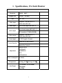
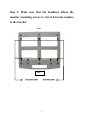
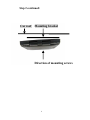
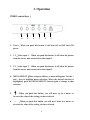
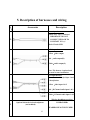
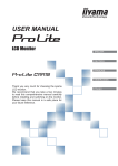
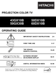
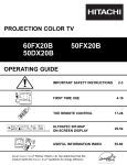
15.4” Wide-screen Overhead LCD Monitor
Installation Guide and Owner’s Manual
RES PN 9100167-90 Rev A
Table of Contents
Section
Title
Page
1
Specification
3
2
Installation
4
3
Operation
8
4
On-Screen Displays (OSDs)
10
5
Description of wiring
12
6
Precautions
13
7
Screws included
14
2
1. Specifications, 15.4 Inch Monitor
Resolution
Display area
Size
1280(H) × 800(V)
331.2(W) × 207.0(H)
15.4" TFT
Video input
Composite Video(RCA)(F) ×2
(NTSC,PAL,SECAM)
Audio input
Stereo Sound Input (RCA)(F) ×2
Audio output
Stereo Sound output (RCA)(F) ×1
IR Transmitter 2.3MHz&2.8MHz
Video output
Composite Video(RCA)(F) ×1
(NTSC,PAL,SECAM)
Power input
DC 12V Negative Ground
Control function
Display Key (6 Key)Control
Remote Key Control
Adjustment
BRIGHTNESS
CONTRAST
SHARPNESS
HUE
SATURATION
Power consumption 3A (MAX)
Temperature
Working: 0~50℃, Storage: 0~60℃
Size/Weight
L:355.60mm, W:349.50mm,
H:46.00mm
4kg ±200g
3
2. Installation
Step 1: Mount the bracket above the headliner to the
roof beam. IMPORTANT! The bracket is directional!
Please use screws in the holes indicated to mount
the bracket to the vehicle. IMPORTANT! NEVER
USE SCREWS THAT COULD DAMAGE THE
VEHICLE ROOF IN ANY WAY!
Front of vehicle
Screws
Screws
Screws
Screws
Rear of vehicle
4
Step 2: Make sure that the headliner allows the
monitor mounting screws to travel from the monitor
to the bracket.
Front
Rear
Screw hole 4 mm
Screw hole 4 mm
5
Step 2 continued:
Car roof
Mounting bracket
Direction of mounting screws
6
Step 3: Mount the monitor to the bracket using the
supplied screws. IMPORTANT! NEVER use any
screws except those provided with the unit! NEVER
use any screw which would damage the vehicle roof!
See step 1
Completed
7
3. Operation
VIDEO control keys:
6
5
4
3
2
1
1. Power:When you push this button, it will turn ON or OFF the LCD
power.
2. V1:Video input 1. When you push this button, it will show the picture
from the source unit connected to video input 1.
3. V2:Video input 2. When you push this button, it will show the picture
from the source unit connected to video input 2.
4. MENU/SELECT:When you press this key, a menu will appear. Use the +
and – keys to highlight menu selections. When the desired selection is
highlighted, press the MENU/SELECT button again to change to that
selection.
5.
┼
:When you push this button, you will move up in a menu, or
increase the value of the setting you have selected.
6.
–
:When you push this button, you will move down in a menu, or
decrease the value of the setting you have selected.
8
VIDEO remote control function:
POWER:When you push this button, the LCD will turn ON or OFF.
V1/V2:Pressing this key, switches between Video Inputs 1 and 2.
MENU:When you press this key, a menu will appear. Use the + and –
keys to highlight menu selections. When the desired selection is
highlighted, press the MENU/SELECT button again to change to that
selection.
UP:When you push this button, you will move up in a menu, or increase
the value of the setting you have selected.
9
DOWN:When you push this button, you will move down in a menu, or
decrease the value of the setting you have selected.
4. On-Screen Displays (OSDs)
OSD MENU LIST
VIDEO 1
BRIGHTNESS :
Adjust the Brightness of Screen.
Adjustment Area:0 ~ 15
BRIGHTNESS
15
VIDEO 1
CONTRAST :
Adjust the Contrast of Screen
Adjustment Area: 0 ~ 31
CONTRAST
21
VIDEO 1
SHARPNESS :
Adjust the Sharpness of Screen
Adjustment Area: 0 ~15
SHARPNE
HUE:
Adjust the Hue of the screen
Adjustment Area: 0 ~ 62
7
VIDEO 1
HUE
SATURATION:
Adjust the Saturation of picture
Adjustment Area: 0 ~ 62
21
VIDEO 1
SATURATION
10
31
MUTE ON :
Turn Mute function on and off.
VIDEO 1
MUTE ON
DISPLAY MODE:
Adjust the display mode to
16:9 (widescreen) ,
4:3 (standard television), or
16:9 FULL (pan-and-scan).
VIDEO 1
DISPLAY MODE 16:9
DEFAULT :
Return to the original Setting of
LCD.
VIDEO 1
DEFAULT (VX.XX)
SAVE AND EXIT :
Save your Personal Setting and exit
to Menu Mode.
VIDEO 1
SAVE AND EXIT
11
5. Description of harnesses and wiring
Accessories
Description
Power input harness:
Yellow: ACC 12V(+) switched
IMPORTANT! DO NOT
CONNECT YELLOW TO
CONSTANT 12V(+)!
1.
Black: Chassis GND
A/V Output harness:
Yellow:video output
Red:audio output(R)
2
White:audio output(L)
Note: This harness is optional and
not used in some installations.
A/V Input harness:
Note: See wire labels for Input 1 and
2 identification.
Yellow:video input 1 & 2
3
Red:R Channel audio input 1 & 2
White:L Channel audio input 1 & 2
Optional infrared wireless headphones
4
Wireless headphone receiving
2.3MHz/2.8MHz
(not included)
HEADPHONE NOT INCLUDED!
12
7. Precautions
1. Do not apply pressure to the LCD screen.
2. Do not get LCD wet to clean it! If you need to clean it, please use a clean
damp cloth.
3. Please do not add any parts or use any accessory which is not provided
from the manufacturer.
4. Don’t use or store in high temperature. (Storage 0~70℃, Operating ~60℃)
5. When you connect power, please make sure Positive and Negative are
correct, or damage could result.
6. Please be careful when moving the monitor, so as not to damage the LCD.
7. THIS VIDEO ENTERTAINMENT SYSTEM, LIKE ALL OVERHEAD
VIDEO PRODUCTS, IS NOT INTENDED FOR VIEWING BY THE
DRIVER, AND IS TO BE INSTALLED ONLY TO BE VIEWED BY
REAR-SEAT OCCUPANTS. IMPROPER INSTALLATION COULD
DISTRACT THE DRIVER OR INTERFERE WITH SAFE OPERATION
OF THE VEHICLE, WHICH COULD RESULT IN SERIOUS INJURY
OR DEATH, AND COULD ALSO VIOLATE STATE LAW. THE
SUPPLIER DISCLAIMS ANY LIABILITY FOR ANY BODILY INJURY
OR PROPERTY DAMAGE THAT MAY RESULT FROM ANY
IMPROPER OR UNINTENDED INSTALLATION AND/OR USE.
WHEN YOU DO THE INSTALLATION:
1. Please connect the power to ACC, instead of IGN or BAT.
2. If you connect the power to IGN, the monitor might
shut down when you start the engine.
3. If the monitor shuts down when you start the car, please
re-start the car.
13
8. Screws included
1:M4×0.7 L= 5 mm screw×10
2:ψ4
L= 10 mm screw×10
14