1
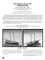
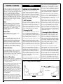
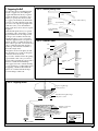
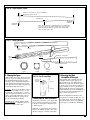
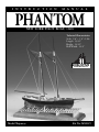
I N S T R U C T I O N
M A N U A L
PHANTOM
NEW YORK PILOT BOAT, 1868
Technical Characteristics
Scale: 1/8” = 1’ 0” (1:96)
Length: 13-1/2”
Height: 13-1/2”
Hull Width: 2-1/2”
Model Shipways
Kit No. MS2027
Model Shipways Kit No. 2027
PHANTOM
New York Pilot Boat, 1868
By George F. Campbell, 1960
Updated Instruction Manual By Ben Lankford
Incorporating suggestions by model builder, Arthur Glaser
The Model Shipways plans for Phantom were prepared in 1960 by Mr. George F. Campbell, who passed away
several years ago. Mr. Campbell was a noted British marine artist, author, naval architect, and historian. He was
a member of the Royal Institute of Naval Architects. One of his most noteworthy publications is China Tea
Clippers. He also developed the drawings for the Cutty Sark restoration in England, developed the Model
Shipways kit of Rattlesnake, and authored Model Shipways’ model handbook, Neophyte Shipmodeler's Jackstay.
The Model Shipways plans for Phantom are based on hull lines provided by Howard I. Chapelle, taken from
a builder’s half-model in the Smithsonian Institute. Deck details and rigging are based on photo information
from the Peabody Museum of Salem, Massachusetts.
©2006 MODEL SHIPWAYS, INC.
Sold & distributed by Model Expo, a division of Model Shipways, Inc. • Hollywood, FL 33020
www.modelexpo-online.com
A Brief History
The Phantom and Pet, sister schooners, were built in 1868-69 at the
Lawlor yard in East Boston, Massachusetts for the Boston port pilots.
Dennison J. Lawlor designed them, as is evident from his “trademarks”:
plumb stem, sharp entry, abrupt bilges amidship, very easy run, and drag
of keel. These characteristics persist over his long period of
successful designing.
2
Phantom was sold to the Sandy Hook (New York) pilots and operated
out of New York for several years. On March 14, 1886, Phantom was the
first to aid the sinking British liner S. S. Oregon off the coast of Long
Island. Her crew oversaw the orderly rescue of 852 people, 400 of whom
were aboard when she returned to port. At the time, she was listed as
New York Pilot Boat No. 11, displaying those numerals on her main sail.
She was lost in the Great Blizzard of March, 1888. The boat keeper,
cook, and four seamen went down with the ship.
CONSTRUCTION STAGES & TABLE OF CONTENTS
Brief History
Introduction/Credits
Before You Begin
How to Work With the Plans & Parts
What You’ll Need to Start Construction
Painting & Staining the Model
Pg 2
Pg 2
Pg 4
Pg 4
Pg 5
Pg 6
Stage A: Shaping the Pre-Carved Hull
1. Hull Templates
2. Carving the Hull
3. Carving the Deck & Bulwarks
Pg 6
Pg 6
Pg 6
Pg 6
Stage B: Completing the Basic Hull Structures
1. Installing the Keel, Stem & Sternpost
2. Installing the Rudder
3. Drilling the Larger Holes in the Hull
4. Holes to Be Drilled as Work Progresses
5. Planking the Deck
6. Installing the Bulwark Stanchions & Cap Rail
7. Coppering the Hull
Pg 8
Pg 8
Pg 8
Pg 8
Pg 8
Pg 8
Pg 8
Pg 8
Stage C: Mounting the Hull
1. Launching Ways
2. Mounting Board with Two Pedestals
Pg 10
Pg 10
Pg 10
Stage D: Adding the Hull Details
1. Wheelbox, Companionways & Skylight
2. Britannia Castings
Pg 10
Pg 10
Pg 10
Stage E: Mast & Spar Construction
1. Shaping the Lower & Top Masts: Fore & Main
2. Assembling the Fore & Main Masts
3. Shaping the Spars
4. Main Boom & Gaff Assemblies
5. Mounting the Mast Assemblies & Bowsprit
Pg 10
Pg 10
Pg 10
Pg 11
Pg 11
Pg 11
Stage F: General Rigging Information
1. Rigging Sail Lines
2. Choosing the Right Size Lines
3. Applying Beeswax to the Lines
4. Seizing the Lines
5. Blocks, Strops & Fittings
Pg 12
Pg 12
Pg 12
Pg 12
Pg 12
Pg 12
Stage G: Standing Rigging
1. Bowsprit Rigging
2. Shrouds
3. Stays
4. Footropes
Pg 13
Pg 13
Pg 13
Pg 13
Pg 13
Stage H: Running Rigging
1. Fore & Mainsail Rigging
2. Jib & Fore Staysail Rigging
3. Main Topmast Staysail & Gaff Topsail Rigging
4. Belaying the Running Rigging
5. Final Touches
Pg 13
Pg 13
Pg 13
Pg 13
Pg 13
Pg 13
Scale Conversion Table
Rigging Line Diameters
Millimeters/Inches Conversion Formulas
Bibliography
Pg 14
Pg 14
Pg 14
Pg 15
3
BEFORE YOU BEGIN
The Phantom is an interesting model for
beginner and expert alike. This kit contains a solid hull which has been
machined carved from select, mediumhard, fine-grained basswood. This style
hull provides a quick and easy lesson in
the basic shapes and proportions of hull
design and helps to develop woodworking
skills. Although the exterior of the
Phantom hull has been carved close to
the hull lines as shown on the plans, further carving and sanding is necessary for
reasons of accuracy. Shaping and finish-
HOW TO WORK WITH THE PLANS & PARTS
Before starting model construction, examine the kit and study the plans carefully.
Familiarizing yourself with the kit will
serve two purposes. First, it will let you
determine that all parts have been supplied as listed. And second, you’ll be surprised at just how quickly handling the
parts allows you to better understand the
kit requirements. Try to visualize how
every part will look on the completed
model. Also, determine ahead of time
what must be done first. The instructions
will help you in this regard, but a thorough knowledge of the plans at the outset
is essential.
It is suggested that all small fittings and
hardware be sorted into labeled boxes or
compartments to avoid loss during the
building process.
ing the hull to its final shape are dis-
1. The Plans
cussed in the instructions.
Three Plan Sheets and a Template Sheet
are provided:
Constructing the Phantom model also
1. Arrangement & Lines - Sheet 1 of 3
will provide you with the opportunity to
2. Rigging Plan - Sheet 2 of 3
3. Suggested Simplification of Rigging
develop some scratch-building techniques.
During construction, you may want to
substitute some of the kit fittings with
your own creations. By all means try
them, especially if you think you can
improve the model.
If you are a beginner, take your time.
This model is fairly simple to build but it
still has a fair amount of detail and small
parts. Make sure you complete one stage
before moving to the next. When something goes awry, consider doing it over.
Completing this model will prepare you
for a more complicated model such as
the Sultana or Fair American. The
Sultana is another solid hull model, but
has more rigging and deck detail. Fair
American is outfitted with a plank-onbulkhead hull that will take you to another level of difficulty. In the meantime,
happy modeling!
4
3. Understanding Hull Lines
Beginners may not be familiar with hull
lines. Buttock lines are vertical longitudinal planes cut through the hull.Waterlines are horizontal planes, and sections
are transverse vertical planes. All of these
lines define the hull shape and are used
by the draftsman to fair the hull form
(create regular even curves). A complete
set of hull lines is shown on the plans.
4. Kit Lumber
Your kit may contain European limewood, as a substitute for the basswood
most of us are familiar with. Both woods
are similar in grain and workability. In
fact, limewood has superior bending qualities. This will be helpful, since a few of
Phantom’s rails must be bent to the proper curve. Following are three different
methods of bending and shaping wood.
Steam bending - This is done by holding
the wood piece you wish to bend over a
kettle of steaming water and then bending
it. Hold the wood in position until it
cools. It should remain nearly in that position, but may spring back slightly.
Details - Sheet 3 of 3
4. Hull Templates on heavy paper stock
for hull carving
The Phantom kit is manufactured to a
scale of 1/8” = 1’ 0”. Plan sheets 1 and 2
are drawn to the exact scale that the
model is to be built, except where some
details have been enlarged for clarity.
Most dimensions can be lifted directly off
the plans by using a set of draftsman
dividers or by using a “tick” strip, which
is simply a piece of paper used to “pick
up” the dimensions (a roll of calculator
tape works very well). Lay your paper
strip over the plan and mark the lengths
of items carefully with a sharp pencil.
Then use the strip to transfer the marks to
the wood or item to be made to scale.
2. Making Allowances
Along the Way
Try to be exact when following the plans,
but use common sense along the way. You
may need to make adjustments or allow
for small differences in how your model is
shaping up; perhaps your mast has too
much rake (the angle at which it sits).
When lines go to belaying points they
should not drape over parts or conflict
with other lines. If necessary, move a
belaying point or a fairlead. In other
words, put yourself on the ship and use
your judgement.
Soaking - Another method is to soak the
piece in warm water for several hours.
Try adding a little household ammonia to
the water. You can also use pure ammonia. This speeds up the soaking process
and makes the wood fibers slippery so the
wood can be easily bent. After soaking the
wood, shape it to the desired
position,using a form. Let it remain there
until it has dried completely.
Hot iron - You may also bend wood
quickly over a soldering iron, but don’t let
it get too hot. Large soldering irons with a
tubular end is ideal. The tube near the
handle will not be as hot as the very end.
It is also possible to purchase model
plank-bending irons commercially. They
are designed for controlled heat.
5. Cast-Metal Fittings
The kit is supplied with Britannia metal
castings. The Britannia metal is a great
improvement over the white metal that
was used in some older kits. Unlike white
metal and pewter, Britannia does not contain lead, so there are no possible corrosion problems. Many of these fittings,
however, will require final finishing
before they are suitable for installing on
the model.
Before painting the cast-metal fittings,
clean them up by removing all the moldjoint flash. To do this, use a No. 11 hobby
blade to cut the flash, then file or sand it
WHAT YOU’LL NEED TO START CONSTRUCTION
with fine sandpaper. It is also suggested
that you clean the fittings thoroughly with
warm soapy water before applying primer.
Make sure they are rinsed thoroughly and
allowed to dry before painting.
6. Soldering & Working
with Brass
The Phantom had some iron fittings that
you can make from brass which you solder together. However, you may desire to
use the simplified methods shown on
plan sheet 3 to eliminate much of the soldering. If you do solder, the secret is to
keep the parts to be soldered clean, and
keep the end of your soldering iron clean
and well tinned. File or sand the parts,
then keep your fingers off. Heat the parts
first, then touch the solder. File off any
excess solder.
The following tools and supplies are recommended for the construction process.
Modelers who have built before may have their own favorites.
A. Knives
1. Hobby knife
2. No.11 blades
B. Files
Set of needle files
C. Clamps
1. A few small C-clamps
2. Wooden clothespins
3. Rubber bands, #16 and #33
D. Tool Set (A small carving tool set or individual gouges and chisels
for shaping the hull.
E. Sharpening Stone (Necessary to keep tools razor sharp)
F. Boring Tools
1. Set of miniature drills: #60 to #80
2. 1/16”, 3/32” and 1/8” drills
3. Pin vise
G. Miscellaneous
1. Tack hammer
2. Tweezers (a few)
3. Small fine pointed scissors
4. Miniature pliers
a. small round
b. flat nose
5. Bench vise (small)
6. Soldering iron or torch
a. solder
b. flux
7. Sewing thread (for seizing; other rigging in kit)
a. black
b. tan
8. Beeswax block (for treating rigging lines)
9. 1/2” or 3/4” masking tape
10. Wire cutters (for cutting fine wire and strip metal)
H. Sandpaper - Fine & medium grit garnet or aluminum oxide (#100 to #220)
I. Sail Cloth - Light weave cotton or linen cloth if you intend to add sails.
A suitable cotton cloth is available from Model Expo.
J. Finishing
1. Paint Brushes
a. fine point for details
b. 1/4” to 1/2” flat square for hull
K. Supplies (will be covered in detail in the Painting & Staining section and
throughout the instructions)
1. Paints
2. Primer
3. Stains and varnish
4. White or Carpenter’s (yellow) wood glue
5. Super glue
6. Five-minute epoxy glue
7. Wood filler
Note about glues: White glue, or Carpenter’s wood glue (yellow in color; also available in
tan color), will suffice for most of the model. Five-minute epoxy provides extra strength
for gluing fittings. Cyanoacrylate glue (super glue), such as Jet, can be used for quick
adhesion and is ideal for adding a touch to a rigging seizing to hold it in place. The best
super glue for most applications is a medium viscosity gap-filling type. The watery-thin
type is recommended to fill a narrow crack by capillary action. Contact cement or model
airplane-type cement is best for gluing the scribed deck sheeting. White glue will warp
the wood sheet.
5
PAINTING & STAINING
It may seem strange to begin an instruction
manual with directions on applying the finishes to the model. Not so! Much time and
effort can be saved, and a more professional
result can be obtained, if the finishing
process is carried out during construction.
Proper timing in application of finishes and
the use of masking tape to define painted
edges should eliminate unsightly glue marks
and splotchy stained surfaces. In the end,
following these general suggestions will be
to your advantage.
Paint
Use a flat-finish paint such as the model
paints made by Floquil, Polly-S, Testors,
Humbrol, and Model Masters. You could
also use artist’s paints by Jo Sonja (used by
many bird carvers) or Holbein Acryla
Gouache. These paints are a combination
acrylic-gouache.
Paint Colors
The recommended color scheme for the
Phantom is shown on the plans.
Primer
Use a grey primer. Floquil is excellent. The
grey color will highlight sanding scratches
and other defects better than white primer.
Prime all woodwork to be painted, and
prime all metal fittings. Lightly sand the
primed items. Use a spackling compound,
such as Pic-n-Patch brand, to fill any scratches and defects, then re-prime. Careful! Do
not prime parts to be stained or varnished.
Stains & Finishes
For natural finished wood, use a protective
coating after staining, such as low sheen
polyurethane varnish or the Floquil coatings. You can also use an oil-resin mix such
as natural Minwax. Floquil stain, or Minwax
stains can be used to tone the wood.
Brushes & Procedures
Use good quality soft sable or synthetic hair
artist brushes. A small pointed brush is good
for details. For the main hull areas, use a 1/4
to 1/2-inch flat brush.
Before painting, clean the model with a tack
rag. Apply your paint in smooth even
strokes, overlapping the strokes as you go.
Thin the paint enough to eliminate brush
strokes, but not run. You will need four or
five coats of the light colors to cover the grey
primer, and maybe only two coats of the
dark. Check your finish between coats, and
sand or add spackle as necessary to get rid
of any blemishes.
STAGE A
SHAPING THE PRE-CARVED HULL
Sanding alone will not shape the hull
enough to precisely match the hull lines.
Actual carving should prove to be minimal,
but some carving is required, especially at
the rail, keel, bow, and stern areas. Particular
care should be taken to shape the stern
properly, being certain to maintain the symmetry above the rudder.
make sure they are fitted perpendicular to
the keel. Carve until the template fits reasonably well, then use sandpaper to obtain the
final shape. At first, the templates will not fit
too well. You must compare the template to
the hull and visually decide where to remove
wood. Cut a little off, then re-check the template. Sand the stern with a sanding block.
Notice that along the top edge of the hull
there is a “waist”. The hull planking is thicker below the waist than in the bulwarks.
Consequently, there is a little step in the hull
side. The templates show this step.
Finally, draw a few horizontal pencil lines
(like waterlines) and the station lines on the
hull. Use these to visually check the shape of
the hull. Hold the hull at various angles, and
look to see if the pencil lines are fair (even).
If you have any unfairness, dips or bumps,
they can usually be found with this visual
check. You can also use a stiff stick of wood,
about 1/8-inch square, to lay on the hull at
various locations. Dips in the hull will show
up under the stick.
1. Hull Templates
For exact carving to hull lines, a template is
required for the hull profile and each of the
nine stations (see figure 1). A template sheet
is provided in the kit, printed on heavy
stock paper. Cut the templates out carefully
with a No.11 hobby blade. Do not use scissors! You will want a nice smooth edge.
2. Carving the Hull
Cut a wooden block from scrap to about 2”
x 1” x 3/4” thick. Screw the block to the
deck so the model can be held in a bench
vise for carving. First, check the accuracy of
the profile and correct it as necessary, using
a long sanding block (see figure 2).
3. Carving the Deck & Bulwarks
Next, mark the centerline, rabbet lines (where
hull meets keel), and station lines on the
model (see figure 3). Place the station marks
on the center of the hull bottom and on top of
the rail so the marks won’t be carved off as
you work. This illustration also shows where
excess wood must be removed from the hull.
Start carving approximately at Template
Station 5 (maximum beam) and progress forward, then aft, using chisels and gouges to
cut away excess wood. Avoid carving
against the grain by shifting forward or aft
of Station 5 until you find a spot where you
are going with the grain. Basswood carves
easily so you probably won’t have much
problem with the grain.
Carve very slowly, and take off a little wood
at a time. Fit the templates as you go, and
Make yourself a temporary cradle to secure
the hull while carving (see figure 4). This
cradle also will serve to hold the model for
most of the remaining work. Make the cradle so the model sits in it with its waterline
parallel to the baseboard and table. The top
of the cradle should be below the waterline.
Later, when you are ready to paint, or copper, attach a pencil on top of a wooden
block, and slide it along the table to mark
the location of the waterline.
The machine-carved hull has bulwarks
approximately 3/16” thick. They are thicker
than required, so they won’t break while
inside the kit box. The upper surface should
be cut to the underside of the cap rail. After
you carve the outside of the hull, including
the step at the waist, the bulwarks will then
be only about 1/16” or 3/32” thick. If necessary, carve the inside of the bulwarks so that
the final bulwark thickness above the waist
is as close to 1/32” thick as you can get it
without damaging the bulwark (see figure 5
for what must be removed). This is the most
FIG. 1 - Cutting Out the Hull Templates
RL
RL
Cut out
with No. 11
hobby knife
CL
W
Kit templates
5
Profile
(fwd)
Profile
(aft)
CL
Anywhere two colors meet, use masking
tape. Electrician’s black plastic tape is ideal.
It leaves a nice edge and is not overly sticky.
Do not use drafting tape. The edges are
wrinkled and paint may run under them.
6
PROFILE
R
STATION
difficult part, so work slowly and be careful
not to break off the bulwarks as you carve
(see figure 6). After carving, sand the surfaces smooth.
FIG. 2 - Carving the Hull
Template
The deck will be covered with the scored
planking sheet included in the kit, unless
you desire to lay individual planks as an
option. In any case, you must first take a
chisel and square up the corners at the deck
step, the transom, and at the bow, and sand
the deck smooth (see figure 7).
Bench vise block
Next, make a template of the deck camber
and shape or sand the deck curvature as
necessary. While doing this, check to make
sure the bulwark height is correct. If necessary, carve the deck down so the proper
height is maintained.
FIG. 3 - Marking the Guide Lines
Rabbet
Wood to be
cut away
Mark stations
Mark rabbet
Mark CL
At this stage, the hull should be fully
carved. Go over the entire hull with sandpaper, using #220 grit for the final smoothing.
Be careful not to round the upper edges of
the rail or at the rabbet. These should be
sharp corners.
RAIL
Fit
Waist templates
Mark stations on top of rail
FIG. 5 - Gauging Bulwark Thickness
FIG. 4 - Making a Cradle
Use kit templates
for shape
STA 2
Sanding block
STA 5
Line with felt
to protect hull
Approx 3/16"
1/32"
1/32"
STA 7
Carve inside
of bulwark
Cut slot
for keel
1/8" - 1/4"
wood
Deck
Waist
1/16"
CRADLE
AFT
Removed by outside carving
A
Waterline
FWD
B
A=B
FIG. 6 - Carving the Hull
FIG. 7 - Squaring Up Some Corners
FWD
Bulwark
Square up corner
Step
Deck
Carve out bow
Deck
Use gouge first
Smooth with
chisel & sand
Carve out
stern area
CARVING BULWARKS
7
STAGE B
FIG. 8 - Installing the Keel, Stem & Sternpost
COMPLETING THE BASIC HULL
STRUCTURES
1. Installing the Keel, Stem
& Sternpost
Pre-cut the keel, stem and sternpost and
install them (see figure 8). Make sure the
grain of the wood is in line with the piece.
Use some scarf joints as shown in the
sketch. Use pins or dowels to position the
parts before gluing. Scrape off any glue
squeeze-out. Fill any gaps remaining at
the glue joints with wood filler and then
sand.
Glue
Pins
Scarf joint
FIG. 9 - Installing the Rudder
Fits into hole in hull
At this stage, drill the pilot holes through
the keel for launching ways or pedestal
mounting.
2. Installing the Rudder
The rudder can be made now or later (see
figure 9 for construction). The pintles and
gudgeons are made from the brass strip
provided, or by using paper strips.
3. Drilling the Larger Holes
in the Hull
Before going any further with the details,
drill all the large holes in the hull. These
would include a hole for the rudder post
and bowsprit, and two mast holes. File
the bowsprit hole square after drilling.
For the mast holes, make a template so
you will drill at the correct mast angle
(see figure 10 for some ideas).
4. Holes to be Drilled as Work
Progresses
There will be a few other holes to drill as
the work progresses. For example, the
hawse holes for the anchor cable are
drilled through the bulwarks forward.
You will also need to drill small holes for
inserting eyebolts that hold blocks for the
rigging, and holes for pinning various
parts in place.
5. Planking the Deck
Note: On the aft deck area, the plans
show that the planking is parallel to the
bulwarks rather than centerline. If you
use the scribed decking in the kit you will
have to ignore this curvature. For authenticity, however, you could plank this area
of the deck with separate individual
planks.
At the deck step, fit the edge plank (see
figure 11). Next, make a paper template
for each of the two deck areas to fit snugly against the edge planks and the bulwarks. Cut the openings for the masts in
the appropriate templates. Place the tem-
8
Super glue
Gudgeon
Pintle
Pin optional
Brass or paper strips
FIG. 10 - Achieving Proper
Mast Rake
FIG. 11 - Edge Plank at Deck Step
Scored
deck
Angled
hole
Mast
rake
angle
Wood block
drill guide
with hole
Drill guide
with V slot
plates on the scored planking and cut the
planking with a hobby knife.
Along the bulwarks, flush with the deck
or just slightly thicker, there is a waterway-nibbing strake, also called covering
board. If you want to add this detail, cut
the edge off the scribed deck, the width of
the waterway, and glue the waterway to
the edge of the sheet (see figure 12).
Make sure the scored lines of the planking
are parallel to the centerline. Glue the
planking down with contact cement or
model airplane-type cement (see gluing
notes on page 5 ).
Edge plank
Deck step
6. Installing the Bulwark
Stanchions & Cap Rail
Before installing the bulwark stanchions (also
called timberheads), cut the scupper slots in
the bulwarks. Drill a series of small holes
along the scupper, then cut out the slots with
a hobby knife. Sand the slots smooth.
Cut each bulwark stanchion to length and
glue them in place. Cutting and mounting
the stanchions is tedious work, so exercise
great care in the installation. Check the
plans for spacing and appearance. Glue
the rail atop the bulwark and stanchions,
making sure it extends slightly beyond the
bulwark outboard and stanchions inboard.
Use pins to help align and hold the rail in
place (see figure 13). The splash rail forward is added next on top of the main rail.
Steam-bend this in place.
7. Coppering the Hull
FIG. 12 - Waterway Nibbing Strake
Waterway
You have the option of painting the hull
bottom a copper color, or installing the
copper included in the kit. If you plan to
copper the hull, now is the time to do it
before you get any more detail on deck.
Glue
Cut off to add waterway
To copper your Phantom, the kit includes
a roll of 1/4”-wide self-stick copper strip.
You can use the strip in long lengths and
scribe the seams, or cut off individual
plates. Plan sheet 2 shows the size of plate
required.
With the hull upside down, use a pencil
to mark the seams on the hull as a guide.
Begin with the keel at the sternpost and
work up to the waterline and forward,
lapping the plates as you go. The plates
should be applied in belts (see figure 14).
Where one belt goes under the next belt,
this is called a gore end. A lower belt need
only go under the upper belt enough to
form a lap. The belt at the waterline is a
horizontal single strake.
Scored decking
Cut if including
the nibs
FIG. 13 - Stanchions & Rail
Pin
Rail
Though not shown on the plans, the rudder should also be covered. See the photo
on the kit and on the sketch.
If you wish to simulate nails in the plating
(questionable at this scale) you can use a
pounce wheel to indent the copper. Such a
wheel is available from Model Expo.
AFT
Scupper
slot
The copper can be left to tarnish naturally,
or you can make it a weathered blue-green
by applying a chemical called Patina-It.
This is also available from Model Expo www.modelexpo-online.com
Waist
FWD
FIG. 14 - Coppering the Hull
Top row of plates lap
over lower rows
Run this band of plates diagonally bow to stern
STERN
BOW
Belt laps over lower
plates at stern
Cross-section
STERN PROFILE
Knuckle
this plate
Keel
KEEL LAPS
Cap on rudder
9
STAGE C
STAGE D
STAGE E
MOUNTING THE HULL
ADDING THE HULL DETAILS
MAST & SPAR CONSTRUCTION
Before proceeding with additional work it
is best to mount the hull. This step will
help prevent details from becoming damaged during handling and will allow you
to make any alignments that require a
true waterline. Proper mounting of the
hull is very important and will allow the
accurate building and aligning of the
remainder of the model. While any modeler can devise his own mounting, this kit
contains a mounting board and launching
ways system. A second option, is the use
of brass pedestals which can be purchased
separately.
With the model mounted, you are now
ready to add the hull details. Mark the
location of all parts in light pencil.
Measure from some bench mark such as a
mast hole, deck step, or the centerline.
The mast and spar dowels included in the
kit are round, but not tapered. True to
scale, masts and spars should be tapered
along their full length. Note also that the
ends of the boom, gaffs, and masts are
stepped down to provide a shoulder for
an eye band.
1. Launching Ways
1. Wheelbox, Companionways,
& Skylight
Make these parts from the solid wood
blocks provided in the kit, or you could
build them up from sheet wood (see figure 15 for some details). The steering
wheel is a Britannia casting. Paint it to
look like a wooden wheel.
This type of mounting is most suitable
for models without sails. A separate set of
instructions for the ways is included in
the kit.
The skylight has round bars over the
glass. However, at this model scale this
detail is almost impossible. You can paint
the glass area light blue, and if you feel
capable, paint some fine black lines to
represent the bars.
2. Mounting Board with Two
Pedestals
2. Britannia Castings
If you decide to use the mounting board
and pedestals, drill the pilot holes for the
pedestals. The model should sit with the
waterline parallel to the baseboard. If
something went wrong and the balance is
off, you can add a brass shim under one
pedestal to correct it. One pedestal should
be longer than the other, so buy the correct lengths.
Note: It is recommended that either
choice mounting piece be finished before
mounting the Hull Assembly into place.
During mounting, be sure that the rails of
the hull are level with the mount. Future
alignments, especially the masting, will be
gauged from this base.
The cockpit coaming, hawse pipe lips,
anchor, stove pipe, fife rails, ventilator,
pumps, winch bitts, cleats, and bollards
are all Britannia castings. Clean them up,
prime, and paint the parts before
installing them on the model. Most of
these fittings require that you drill holes
in the deck for inserting the fittings. Use a
small amount of glue in the holes and be
careful not to have any glue squeeze-out.
For the fife rails, make sure the belaying
pins holes are clean. You can glue the
brass pins in the holes before installing
the fife rails.
For some scratch-building practice, try
making some wooden or brass fittings and
substitute them for the Britannia castings.
FIG. 15 - Companionway
Sliding top
Glue edge strips
or solid sheet for
top overhang
Strip
Coaming strip, or
carve with block
Carved
TRIM OPTIONS
10
There are two mast assemblies for the
Phantom. They are a fore mast and main
mast and are built up in two sections:
lower and top. Each should be connected
at the doublings by mast caps and lower
band (fore) and spreader (main).
Establishing the Correct Curve of the
Masts: The correct shape of the masts is
shown on the plans. Each of the mast sections should be tapered in a slight (parabolic) curve and not in straight lines (see
figure 16 ). The best way to taper masts
from dowels is to cut the taper into
squares, then octagons, and finish by
sanding into circles (see figure 17 ). For
the Phantom, the diameters are rather
small, so you probably can just hand-sand
the tapers, or chuck them in an electric
drill and sand the taper.
Shaping the Mast Heads: As you shape
the masts, square up the mast head at the
top and cut the tenon for the mast cap
(see figure 18 ).
2. Assembling the Masts:
Fore & Main
Next, assemble the two top masts (the
fore is a signal pole) onto the two lower
masts by first gluing the caps in place.
The main mast has a spreader which can
be made from brass wire. Install the topmasts, making sure they line up straight
with the lower masts. Plan sheet 2 shows
enlarged views of the mast details.
When the mast assemblies are completed, stain and varnish them and set them
aside to dry.
Sheet
Solid block
1. Shaping the Lower & Top
Masts: Fore & Main
Note: Even though sails may not be
installed, the fore and mainsail mast
hoops should be installed. These can be
made from brass wire. Wind a wire
around a dowel or drill bit slightly larger
than the mast. Then, cut the winding into
split rings. Glue or solder the ring together. Place the rings on the masts before you
add the main boom rest and before
installing the mast assemblies.
FIG. 16 - Taper On Masts & Spars
Center of a yard, heel of a mast, or maximum
diameter of a gaff or boom
Straight line
Minimum
diameter
Maximum
diameter
This is the desired curve. Mathematically it is a parabola. It's
very close to the arc of a circle. Simply taper the spar gradually from maximum diameter to the end. For yards, make
sure both sides are the same.
FIG. 17 - Shaping the Masts
Taper
required
Dowel
Kit dowel (if tapered)
Draw
square
on end
MAST
Correct parabolic curve
YARD
1st cut
square
3. Shaping the Spars
Main Boom & Two Gaffs: The boom and
gaffs also taper in a slight parabolic curve.
The maximum diameter of these spars
should be about one-third from their fore
end, and then they should taper toward
each end. The forward end is slightly larger in diameter than the aft end.
2nd cut
8 sided
Sanded
round
FIG. 18 - Top of Lower Masts
Tenon to fit
mastcap
casting
Square
Round
Bowsprit: The bowsprit should be square
from the inboard end to about 1/8” outboard, then it should change to a round
shape and taper forward. It is best to start
with a square stick rather than a dowel.
On the inboard end, also cut the tenon
that fits between the winch bitts.
4. Main Boom & Gaff Assemblies
Finishing Spars: When shaping and fitting of each spar is completed, stain, varnish and set them aside to dry.
The main boom and two gaffs require that
jaws be added to their throats for joining
to the masts. Plan sheet 3 illustrates how
to make the jaws.
5. Mounting the Mast
Assemblies & Bowsprit
After staining and varnishing the mast
assemblies and bowsprit, they can be
placed in the holes you drilled into the
hull. The bowsprit hole should be square
to fit the square end of the bowsprit. It is
suggested that you do not glue the masts
and bowsprit into the holes. The rigging
will hold them in position. Furthermore, if
the model gets restored in the future, the
masts can be easily removed.
Check the alignment of the masts and
bowsprit. If not straight, looking aft, or at
the correct angle shown on the plans, you
can shim the holes. If necessary, drill the
holes larger to accommodate shimming.
Drill holes to represent the sheaves in the
main boom. Add the eyebolts, cleats and
chocks to all spars as shown on the plans.
11
STAGE F
FIG. 19 - Seizings
FAKED ON SMALL BLOCK OR SPAR
GENERAL RIGGING INFORMATION
Tuck up & glue
Slip knot
For this model you will be concerned with
six different basic types of lines:
STANDING RIGGING - 1. Shrouds: there
are a total of 6, three on each side of the
ship. They are fixed lines that support the
lower masts and run from the mast bands
on the mastheads to deadeyes and chainplates along the outside of the ship. 2.
Main topmast backstay: similar to a
shroud, but supports the main topmast on
each side of the ship. 3. Stays: are fore and
aft fixed lines that support the masts and
spars. 4. Footropes: are for seamen to
stand on when furling sail;
RUNNING RIGGING - 5. Halliards or
Halliards: these are lines that move and
are used to hoist sails or flags; 6.
Downhauls, Reef tackle, Sheets and topping lift: all these lines move, are used to
work the gaffs, boom or sails. Downhauls
and reef tackle are used to haul down a
spar or sail; Sheets secure the lower ends
of the sails; The topping lift passes
through a block at the masthead and takes
the weight of the main boom by lifting.
You should have no trouble following the
leads and the belaying points. When confronted with options, put yourself “on
board” the real ship and from that perspective decide what you would do.
Clove
hitch
Loop
through line
Wrap
Pull tight,
glue, then
cut off ends
Thread
Cover end
of line
Touch with
super glue
FIG. 20 - Blocks
Fine brass wire, twisted
Twist
Or
Glue
in hole
Becket
Form hook
1. Rigging Sail Lines
The Phantom model is intended to be
completed with sails removed. It looks
better on the launching ways mounting
system. However, even without sails,
some of the rigging lines such as halliards
and downhauls should remain, along
with their lead blocks. Some of the lines
should be hooked together, such as the jib
halliards and downhauls. The running
ends of these lines should be belayed at
their proper locations.
Adding the sail rigging lines on the
Phantom adds tremendously to the look
of the model, especially at the forward
stays where the contrasting black stay and
light running lines, along with their
blocks, create interesting visual detail.
Sail Making Option:
The sails are shown on the Rigging Plan
for those who wish to make them.
Sailmaking details can be found in other
Model Expo instruction books.
12
2. Choosing the Right Size Lines
4. Seizing the Lines
All of the standing (fixed) rigging is done
using the black line in the kit. The black
color represents the permanently tarred
rigging used on the real ship. Use the
heavier line for the shrouds, the stays,
and bobstay. Use the next size for the
backstays and footropes, and use sewing
thread (not in kit) for seizings and lanyards. Lanyards are lines which pass
either through deadeyes to tighten the
shrouds. The natural color lines in the kit
are used for the running rigging that is
reaved through blocks.
Seizing of lines (binding or securing two
lines or different parts of the same line)
can be done as shown in figure 19). To
prevent seizings from unraveling, add a
touch of super glue.
3. Applying Beeswax to
the Lines
Before placing the lines on the model, run
the line through a block of beeswax several times. Then, run the line through your
fingers. This heats the wax slightly and
rubs it into the line. The beeswax will cut
down on fuzz and protect the line from
moisture.
5. Blocks, Strops, & Fittings
The blocks in the kit are so small that it
will not be easy for you to create the exact
detailing. Some modeling shortcuts are in
order (see figure 20).
STAGE G
STANDING RIGGING
FIG. 22 - Gaff Rigging Details
Topping lift
At main only gaff topsail sheet block sheet
knotted off or omitted
Peak halliard
1. Bowsprit Rigging
Begin the standing rigging with the
bowsprit. Plan Sheet 2 shows enlarged
views of the rigging and Plan Sheet 3
shows some model simplifications. Where
paper strip is shown for a simplified iron
band, you could also use some of the selfstick copper stripping included in the kit.
To rail
Throat
halliard
To fife
rail
Peak lines to
boom (main)
fife rail (fore)
Main only gaff
topsail sheet
block
Deck
2. Shrouds
The shrouds are the strong lines that support the masts laterally. They are attached
along the outside of the ship using chain
plates, lanyards and deadeyes. The chain
plates are made of brass wire or strip. To
set up the shrouds, make a temporary jig
of brass wire to space the deadeyes as you
do the seizings (see figure 21 and plan
sheet 2). Keep an eye on the masts as you
rig the shrouds, so you will not pull them
out of line.
FIG. 23 - Main Boom Rigging Details
Topping lift
Stopper cleats
for footropes
Reef pendant cleats
Footropes
3. Stays
Stays also are support lines for spars, but
more especially for masts in a fore and aft
direction. Install all the fore and aft stays
after the shrouds are completed (see plan
sheet 2 for enlarged details at the masthead).
Note that the main topmast back-stays
should set up to a tackle at the rail rather
than deadeyes. The tackle part is a running line, therefore it should be tan in
color. The fixed portion above the tackle is
black like the other stays.
4. Footropes
Footropes are required on the bowsprit
and the aft end of the main boom.
Beeswax these thoroughly so they will
hang in a smooth curve.
FIG. 21 - Spacing the Deadeyes
with a Jig
Boom sheet
Cleat for
peak lines
Traveler
To bollard
STAGE H
RUNNING RIGGING
1. Fore & Mainsail Rigging
Gaff and boom rigging details are next
(see figures 22 and 23). The main gaff can
be rigged in the up position or down on
top of the boom. However, in the up position the appearance is fuller. See the
model on the kit box.
The reef pendants and tackle can be omitted if no sails are installed.
2. Jib & Fore Staysail Rigging
Pull tight & seize
Deadeye
Make a little
longer than
required. Let
lanyards pull
shrouds tight
To rail
Temporary wire jig
Rig the Jib and Fore Staysail halliards and
downhauls as shown (see figure 24). Since
there are no sails, the sheets will be omitted. If you add sails or furled sails, the
sheets must be included.
3. Main Topmast Staysail
& Gaff Topsail Rigging
These can be rigged similar to the jib.
Connect the halliards and downhauls
together. The sheets can be omitted if no
sails are used, or you can include the
sheet and knot it off at a block.
4. Belaying the Running Rigging
The belaying points shown on the plans
illustrate a solution to belaying all the
lines, but it is certainly not the only solution. Lines were belayed differently on
various ships. You must, however, use
some common sense. The lines must lead
easily to the belaying points. Each belaying point should have a coil of rope (see
figure 25 for some modeling ideas).
5. Final Touches
After all the rigging is in place, re-check
every line, and make sure all the seizings
are sound. If necessary, add another touch
of super glue to seizings. Check to see if
there are any shiny places on the rigging.
If necessary, touch up the standing rigging with black paint, or black liquid shoe
polish. For running rigging, use a tan
stain, or brown liquid shoe polish.
Check to see if any of the painted wooden
parts were marred or scratched during the
rigging process and touch up as necessary.
Congratulations—you’ve done it! Your
model should now be complete. We
hope you like the results and look forward to helping you with your next ship
modeling project.
13
RIGGING LINE DIAMETERS
FIG. 24 - Jib & Fore Staysail
Halliards & Downhauls
.10mm (.004")
Halliard
Jib stay
.20mm (.008")
Hook together
Jib & Forestay
sail similar
.25mm (.010")
Downhaul
.40mm (.016")
.50mm (.020")
.60mm (.024")
.75mm (.030")
.80mm (.032")
FIG. 25 - Rope Coils
Belay line, glue & cut
off end add rope coil
separately
.90mm (.035")
Fine
thread
Thread
knot
Round or oval stick
about 3/8" D
ALTERNATE COIL
Wrap a coil over
the thread
.95mm (.037")
1.00mm (.039")
1.20mm (.047")
Fit the knot
behind cleat
Glue
1.25mm (.049")
Touch knot in thread
touch with super glue &
cut off ends
Add glue here if coil
does not lay flat
1.30mm (.051")
1.50mm (.059")
1.60mm (.063")
CONVERSION TABLE FOR 1/8" SCALE
Diameters for Lifesize Vessel
R I G G I N G
Diameters in Tenths of an Inch
.3125"
.375"
.5"
.625"
.75"
.875"
1.00"
1.25"
5/16"
3/8"
1/2"
5/8"
3/4"
7/8"
1"
1-1/4"
Lengths for Lifesize Vessel
14
1.70mm (.067")
Diameters Converted to 1/8" Scale
.01 x Inches in 10ths:
.003" (.08mm)
.004" (.10mm)
.005" (.13mm)
.006" (.15mm)
.008" (.20mm)
.009" (.23mm)
.010" (.25mm)
.013" (.33mm)
B L O C K S
Lengths Converted to 1/8” Scale
1.75mm (.069")
2.00mm (.079")
2.50mm (.098")
FORMULAS FOR CONVERTING
MILLIMETERS AND INCHES
4"
.04" (1.02mm or 1/32")
5"
.05" (1.27mm or 3/64")
6"
.06" (1.52mm or 1/16")
1 mm = .03937 of an inch
7"
.07"(1.78mm or 5/64")
8"
.08" (2.03mm or 5/64")
To find tenths of an inch:
.03937" x mms = tenths of an inch
10”
.09" (2.28mm or 3/32")
12”
.13” (3.30mm or 1/8”)
To find mms from tenths of an inch:
Tenths of an inch ÷ .03937" = mms
The Latest* Kits from Model Shipways
*As of the printing of this manual, some of these kits were not yet released. Please see our website (www.modelexpo-online.com) or call
1-800-222-3876 (Mon-Fri 9-5 ET) for availability, prices and expected in-stock dates.
NEW!
HARRIET LANE, UPDATED!
DESPATCH #9
Built in New York for the U.S. Revenue
Service in 1857, the Harriet Lane was
powered by a combination of steam
and sail. She was 180 ft. long, with a
30 ft. beam, and carried a 30 lb.
Parrott rifle, plus three 9" smooth-bore
Dahlgrens. Her design clearly illustrates the transition from sail to steam.
The Diesel harbor tug Despatch #9 was
built for the Marine Corps in 1945 at
Tampa, FL from a US Army design.
Later sold to Standard Oil of California,
she worked oil barges in the San
Francisco Bay area. Powered by a
Busch-Sulzer 6-cylinder engine, she
was equipped with practically every
modern device of the time, including
electric capstan, electric towing
machine and watertight doors.
Despatch #9 was 85 ft. long with a 23
ft. beam.
BACK BY POPULAR DEMAND
SOLID HULL KIT
NEW!
Harriet Lane features a machine carved
hardwood hull which needs only light
shaping and sanding. We provide
plank-scored basswood for decking
and cabins, spars and hardwood
blocks. Ladders, anchors, paddle
wheels, two ship’s boats, four cannon
with carriages and numerous other fittings are finely cast Britannia metal. We’ve upgraded the kit to include laser cut paddle wheel
covers. Newly Detailed plans and newly written clear instructions by master ship modeler, Ben
Lankford, are easy to follow. (Baseboard and brass pedestals are not included.)
Kit features a pre-shaped, machine
carved solid wood hull, shaped deck
house and superstructure. Other wooden parts include dowels, strips, sheets and blocks. Brass wire and airports, plus over 80 cast
Britannia metal fittings outfit your model just like the real tug. Clear plans and instructions make
building easy. (Wooden display base and brass pedestals are not included.)
Solid Hull Kit • Entry Level • No. MS2010 • Length 13-1/2" / Height 13-1/2" / Scale 1/8" = 1 ft. (1:96)
Entry Level • No. MS2011 • Length 13-1/2" / Height 7-1/2" / Scale 5/32" = 1 ft.
Harriet Lane Paint Set: Seven 1 oz. bottles of Model Shipways paint: No. MS2010MS
Walnut Display Base: Routed and ready for finishing. 20" x 4-1/2". No. RH4520
Brass Display Pedestals: Pre-drilled from top to bottom and slotted to fit the keel. You’ll need three.
Height 1-1/8" No. MS0812
Despatch No. 9 Paint Set: Eight 1 oz. bottles of Model Shipways paint: 1 each/MS4839 Primer, MS4830
Hull/Spar Black, MS4801 Bulwarks Dark Green, MS4816 Deck House Dark Buff, MS4835 Bright Red Trim,
MS4828 Iron/Cannon Black, MS4823 Clipper Pearl Gray, MS4962 Aluminum. No. MS2011MS
Walnut Display Base: Routed and ready for finishing. No. RH4512
Brass Display Pedestals: Pre-drilled from top to bottom and slotted to fit the keel. You’ll need two. No. MS0812
FAIR AMERICAN,
NEW!
REVOLUTIONARY WAR BRIG, C. 1778
PLANK-ON-BULKHEAD KIT
Fair American is a reproduction of a model built over
200 years ago, now on exhibit at the U.S. Naval
Academy Museum at Annapolis, MD. She is said to
represent the 14-gun privateer Fair American sailing
out of Charleston in 1778.
Plank-on-bulkhead construction uses high quality
basswood, the preferred wood of professional modelers. All structural hull parts and major fittings are
laser cut, so they fit together with remarkable ease.
The kit contains over 60 cut or shaped wooden
parts, plus 120 extra wood strips for a second layer
of planking, should you wish to build your model
with a double planked hull. More than 500 fittings of
wood, brass and Britannia metal fittings include 14
brass guns on wooden carriages, cannon, chainplates, bell, anchors and wheel. Seven plan sheets a
48 page instruction book by Erik A.R. Ronnberg, Jr.
and Ben Lankford, plus a 38-page guide to planking the hull make building easy.
(Display base and brass pedestals are not included.)
Intermediate Level • No. MS2015 • Length 26-1/2" / Height 22" / Scale 1/4" = 1 ft.
Fair American Paint Set: Six 1 oz. bottles of Model Shipways paint: 1 each/MS4839 Primer, MS4830 Hull/Spar
Black, MS4803 Hull Tallow, MS4802 Bulwarks Red, MS4825 Deck Light Gray, MS4969 Gold. No. MS2015MS
Walnut Display Base: Routed and ready for finishing. 20" x 4-1/2" No. RH4520
Brass Display Pedestals: Pre-drilled from top to bottom and slotted to fit the keel. You’ll need two sizes for level
display. No. MS0812 Height 1-1/8" No. MS0813 Height 1-3/8"
DAPPER TOM
NEW!
SOLID HULL KIT
During the early 19th century, many
Baltimore clippers were granted privateering licenses by the US government.
Only a fast, well handled ship could be
reasonably sure of reaching its destination. Privateers like the Dapper Tom
depended on their sailing abilities and
fire power to prey on foreign shipping
and to escape the British men-of-war
patrolling the high seas.
Kit features a machine carved basswood hull with accurately shaped bulwarks and transom. Fittings include 8
cast metal cannon, mast caps,
anchors, capstan and gratings, brass
eyebolts and belaying pins, plus hardwood blocks and deadeyes. Scribed decking, wooden
masts and yards, and three diameters of cotton rigging provide the finishing touches of authenticity. With the help of clearly drawn plans and illustrated instructions, even first time builders
can finish an impressive model. (Display base and brass pedestals are not included.)
Entry Level • No. MS2003 • Length 24"/Height 18"/Scale 5/32" = 1 ft.
Dapper Tom Paint Set: Six 1 oz. bottles of Model Shipways paint: 1 each/MS4839 Primer, MS4830 Hull/Spar
Black, MS4801 Bulwarks Dark Green, MS4803 Hull Tallow, MS4835 Bright Red Trim, MS4828 Iron/Cannon Black.
No. MS2003MS
Walnut Display Base: Routed and ready for finishing. 20" x 4-1/2". No. RH4520
Brass Display Pedestals: Pre-drilled from top to bottom and slotted to fit the keel. You’ll need two sizes for level
display. No. MS0812 Height 1-1/8" No. MS0813 Height 1-3/8"
BIBLIOGRAPHY
1. A Dictionary of Sea Terms, Ansted, A., Brown, Son and Ferguson, 1967.
A useful collection of general definitions.
2. The Ashley Book of Knots, Ashley, Clifford W., Doubleday & Co., 1944.
Great compendium on knots and ropework.
3. The Neophyte Shipmodeler's Jackstay, Campbell, G. F., Model Shipways, 1962.
For the beginner, contains general information on modeling, drawing from
many types of sailing vessels.
5. American Ship Models, Grimwood, Victor R., W. W. Norton, 1942. Bonanza
reprint. Contains much useful information on modeling techniques and a very
good chapter on tools and materials.
Note: Most books are available from Model Expo at
www.modelexpo-online.com. Check current catalog or website for availability.
4. The Ship Model Builders Assistant, Davis, Charles G., Marine Research
Society, Salem, 1926. Sweetman reprint, 1960.
Has many useful articles on model techniques; unfortunately, some of the text
dealing with historical aspects of vessels and their construction is inaccurate.
Beware of anachronisms.
15
Other Fine Kits from
Model Shipways
SULTANA
WILLIE L. BENNETT
Model Shipways Kit No. MS2016
Model Shipways Kit No. MS2032
OUR GUARANTEE
If less than delighted, return your purchase within 30 days in original condition.
BLUENOSE
RATTLESNAKE
Model Shipways Kit No. MS2130
Model Shipways Kit No. MS2028
CHARLES MORGAN
BENJAMIN LATHAM
Model Shipways Kit No. MS2140
Model Shipways Kit No. MS2109
GLAD TIDINGS, PINKY SCHOONER
EMMA C. BERRY
BEDFORD WHALEBOAT
USS CONSTITUTION
Model Shipways Kit No. MS2180
Model Shipways Kit No. MS2150
Model Shipways Kit No. MS2645
Model Shipways Kit No. MS2040
NIAGARA
FLYING FISH
PRINCE DE NEUFCHATEL
PRIDE OF BALTIMORE II
Model Shipways Kit No. MS2240
Model Shipways Kit No. MS2018
Model Shipways Kit No. MS2110
Model Shipways Kit No. MS2120
MODEL SHIPWAYS, INC.
Sold & Distributed by Model Expo, a division of Model Shipways, Inc.
3850 N. 29th Terrace, Hollywood, FL 33020
Toll-Free 800-222-3876 Monday - Friday 9-5 ET • Fax 800-742-7171
SAVE TIME & MONEY ... ORDER DIRECTLY FROM OUR WEBSITE!
http://www.modelexpo-online.com