1
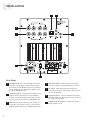
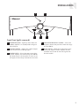
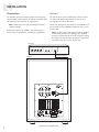
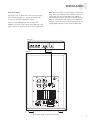
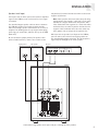
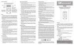
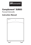
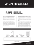
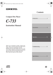
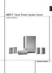
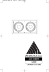
Complement ® SUB105
Powered Subwoofer
Instruction Manual
SAFETY PRECAUTIONS
Important Safety Instructions
7. Wall or ceiling Mounting - The appliance should be mounted to a
wall or ceiling only as recommended by the manufacturer.
WARNING: TO REDUCE THE RISK OF FIRE OR
ELECTRIC SHOCK, DO NOT EXPOSE THIS
APPLIANCE TO RAIN OR MOISTURE.
CAUTION: TO REDUCE THE RISK OF ELECTRIC
SHOCK, DO NOT REMOVE COVER. NO USERSERVICEABLE PARTS INSIDE. REFER SERVICING
TO QUALIFIED SERVICE PERSONNEL.
The lightning flash with arrowhead symbol, within an equilateral
triangle, is intended to alert the user to the presence of uninsulated
dangerous voltage within the product’s enclosure that may be of sufficient magnitude to constitute a risk of electric shock to persons.
9. Heat - The appliance should be situated away from heat sources
such as radiators, heat registers, stoves, or other appliances (including amplifiers) that produce heat.
10. Power Sources - The appliance should be connected to a power
supply only of the type described in the operating instructions or as
marked on the appliance.
11. Grounding or Polarization - Precaution should be taken so that the
grounding or polarization means of an appliance is not defeated.
12. Power Cord Protection - Power supply cords should be routed so
that they are not likely to be walked on or pinched by items placed
upon or against them, paying particular attention to cords at plugs,
receptacles, and the point where they exit from the appliance.
The exclamation point within an equilateral triangle is intended to
alert the user to the presence of important operating and maintenance
(servicing) instructions in the literature accompanying the appliance.
13. Cleaning - The appliance should be cleaned only as recommended by
the manufacturer.
POWER CORD NOTICE FOR INTERNATIONAL OPERATION
14. Non-use Periods - The power cord of the appliance should be unplugged from the outlet when left unused for a long period of time.
To remove all power (supply mains) from the appliance, remove the
plug from the wall outlet.
For 230V, 50Hz operation, select the power cord for your area. Select
the plug for your area at one end and a IEC320 connector at the other.
It is not necessary to make any other changes. If you have any questions, call Russound at 603.659.5170.
Safety Instructions
1. Read Instructions - All the safety and operating instructions should
be read before the appliance is operated.
15. Object and Liquid Entry - Care should be taken so that objects do
not fall and liquids are not spilled into the enclosure through the
openings.
16. Damage Requiring Service - The appliance should be serviced by
qualified service personnel when:
A. The power supply cord or the plug has been damaged; or
2. Retain Instructions - The safety and operating instructions should be
retained for future reference.
B. Objects have fallen, liquid has been spilled into the appliance; or
3. Heed Warnings - All warnings on the appliance in the operating
instructions should be adhered to.
D. The appliance does not appear to operate normally; or
4. Follow Instructions - All operating and user instructions should be
followed.
5. Water and Moisture - The appliance should not be used near water;
for example, near a bathtub, washbowl, kitchen sink, laundry tub,
in a wet basement, or near a swimming pool. The apparatus shall
not be exposed to dripping or splashing liquids and no objects filled
with liquids, such as vases, shall be placed on the apparatus.
6. Carts and Stands - The appliance should be
used only with a cart or stand that is recommended by the manufacturer. An appliance
and cart combination should be moved with
care. Quick stops, excessive force and uneven
surfaces may cause the appliance and cart
combination to overturn.
2
8. Ventilation - The appliance should be situated so that its location or
position does not interfere with its proper ventilation. For example,
the appliance should not be situated on a bed, sofa, rug, or similar
surface that may block the ventilation openings, or placed in a
built-in installation, such as a bookcase or cabinet that may impede
the flow of air through the ventilation openings.
C. The appliance has been exposed to rain; or
E. The appliance has been dropped or the enclosure is damaged.
17. Servicing - The user should not attempt to service the appliance
beyond that described in the operating instructions. All other servicing should be referred to qualified service personnel.
INTRODUCTION
Product Description
The Complement® SUB105 is a compact, high-powered
active subwoofer with a comprehensive feature set for
installer and user convenience. Its powerful amplifier
couples with an acoustically optimized cabinet and
driver to provide high performance with a deep low end
and smooth response.
Features
For installation flexibility, the SUB105 offers stereo linelevel inputs, a line-level LFE input, a balanced line-level
stereo input via CAT-5 cable, and stereo speaker-level
inputs with pass-through.
An adjustable level control, a variable crossover, and a
phase switch allow the user to precisely balance the sub
with the other speakers in the audio system. Frontmounted controls make it convenient for the user to
make adjustments and turn the subwoofer on and off.
An automatic standby mode turns the subwoofer on
as soon as it senses an audio signal and mutes it 20
minutes after the signal ends. A front-panel power
indicator glows amber for standby mode and green for
fully on.
The subwoofer’s attractive compact design provides
versatile placement options without compromising the
home décor.
Applications
The SUB105 is ideal for use in home theater and stereo
music systems. The perfect match for Russound Complement LCR7 on-wall speakers, it can also be used with
any Russound in-wall or in-ceiling speakers.
The balanced line-level RNET A/V input makes the
SUB105 especially useful when the audio source is
remotely located, such as in an equipment cabinet. By
using CAT-5 cable, the installer can avoid transmitting unbalanced signals over long distances, which can
degrade the signal and introduce noise.
Because the subwoofer’s location affects how standing waves are created, correct subwoofer placement is
important to avoid such peaks and nulls. They can’t be
fixed by equalization, which could overdrive the speaker
and amplifier, causing distortion or damage.
The first step toward getting accurate bass response is
to set the subwoofer’s crossover to match the low-frequency roll-off point of the main speakers. Once you’ve
set the crossover, you can then experiment to find the
best possible location for the subwoofer.
Corner placement
Placing the subwoofer in a corner will result in maximum volume, greatest efficiency, and lowest distortion.
This is because the adjacent walls and floor reinforce
the fundamental bass tones. However, corner placement
can also make the subwoofer sound boomy, emphasizing a single frequency above others and resulting in
uneven frequency response.
Other placement options
To get a smoother, more even frequency response, place
the subwoofer at varying distances from the walls of
the room. The key to minimizing standing waves is to
avoid symmetry. Also, place the subwoofer close to the
main speakers. This will help blend and integrate the
sound of the sub and the main speakers. At the very
least, keep the subwoofer in the front half of the room.
A common technique for finding the best location is
to put the subwoofer in the main listening position, at
seated ear height on a sturdy, nonresonant platform.
Play music with ascending and descending bass notes,
such as a jazz recording with a walking bass line. Crawl
around the floor until you find the spot where the bass
sounds smoothest, and where each bass note has about
the same volume and clarity. Avoid positions where
some notes resonate longer or sound heavier than others. When you’ve found the place where the bass sounds
best, put the subwoofer there.
Multiple subwoofers
Subwoofer Placement
Room acoustics and modes
Room acoustics have a great effect on the sound of
speakers, especially subwoofers. When sound is reflected
back and forth between two parallel surfaces, such as
opposite walls in a rectangular room, it creates standing
waves. These make bass response uneven by creating
sound peaks and nulls at certain locations within the
room.
Using multiple subwoofers provides greater dynamic
range and smoother bass response throughout the room
than using only one subwoofer. Placing two subwoofers in the corners behind the main speakers will reduce
room resonances and increase directly radiated sound.
When placing two subwoofers in adjacent corners,
position them asymmetrically to minimize the effects of
standing waves.
3
INSTALLATION
3
4
2
1
5
7
6
Rear Panel
1
4
SPEAKER LEVEL OUT – Pass-through connectors
for main left and right speakers when speakerlevel input is used. Binding posts accept banana
plugs, spade lugs, pin connectors, and bare wire
up to 12 AWG (2.05 mm).
2
SPEAKER LEVEL IN – Connectors for speaker-level
signals from an amplifier or receiver. Binding
posts accept banana plugs, spade lugs, pin connectors, and bare wire up to 12 AWG (2.05 mm).
3
RNET A/V IN – RJ-45 connector for a balanced
stereo line-level signal via CAT-5 cable from an
RNET A/V source output or an RNET A/V Encoder.
4
LINE-LEVEL INPUT – RCA connectors for stereo
line-level signals from a preamplifier or receiver.
5
LFE INPUT – RCA connector for a prefiltered
low-frequency effects signal from a home theater
receiver or processor.
6
VOLTAGE SWITCH – Sets the amplifier to operate
on either 120 V or 240 V. Set this switch to match
the supply mains voltage.
7
POWER CORD RECEPTACLE – Connector for the
supplied power cord.
INSTALLATION
1
5
2
4
3
Front Panel (grille removed)
1
POWER INDICATOR – Lights up amber when the
SUB105 amplifier is in standby mode and green
when fully on.
4
CROSSOVER FREQUENCY CONTROL – Selects the
frequency for the low-pass filter within the range
of 50 to 200 Hz.
2
VOLUME CONTROL – Adjusts the acoustic output
level relative to the incoming signal.
5
3
POWER SWITCH – Selects the power state of the
internal amplifier. Set to Off to keep the SUB105
off, Auto to turn it on only when it senses an audio signal, or On to keep it turned on all the time.
PHASE SWITCH – Allows the speaker phase to be
inverted to improve acoustic response in some
situations. Set to 180° to invert the signal or 0°
for no inversion.
5
INSTALLATION
Connections
LFE input
The SUB105 gives you multiple options for connecting
to your audio system. Choose the option that works best
for your particular situation and equipment.
The low-frequency effects (LFE) input is for use when
the LFE or subwoofer output on the home theater
receiver or processor is turned on.
Connect an RCA patch cable between the SUB105’s LFE
input and the LFE or subwoofer output on the receiver
or processor.
Note: Choose only one connection option. Do not
combine options.
Before you connect the SUB105, turn off the power
switches on all components, including the subwoofer.
Note: The LFE input is not connected to the SUB85’s
internal low-pass filter. Accordingly, the crossover
frequency control has no effect on a signal entering
this input. Use the LFE input only with a signal that
is prefiltered by the receiver or processor.
Receiver
Speaker Outputs
Left
Line Level Output
LFE Output
Right
Left
Right
RCA patch cable
SUB105
Connection using LFE input
6
INSTALLATION
Line-level input
Note: When the LFE or line-level input is connected
to an audio system powered by a different electrical
circuit from the one used to power the SUB105, a
ground loop may result. This causes a low-frequency
hum. To eliminate the hum, connect the SUB105 to
the same electrical circuit as the audio system or use
a ground loop isolator in series with the RCA cable.
This input is for use when the receiver’s or processor’s
LFE or subwoofer output is turned off, or when the
receiver has no LFE or subwoofer output.
Connect a stereo RCA patch cable between the
SUB105’s line-level input jacks and the front left- and
right-channel line outputs on the receiver or processor.
Receiver
Speaker Outputs
Left
Line Level Output
Left
SUB105
LFE Output
Right
Right
Stereo RCA
patch cable
Connection using stereo line-level input
7
INSTALLATION
RJ-45 Using T568A
Wiring Standard
Connections (continued)
RNET A/V input
The RNET A/V balanced stereo line-level input allows
connection to the source equipment via a CAT-5 cable.
This input is an 8-pole RJ-45 connector that uses Russound’s RNET A/V technology. It connects to either an
RNET A/V source output or an RAVE1 RNET A/V Encoder
at the source end.
At the source end, plug the connector into the RNET
A/V jack on the source or the RNET A/V Encoder. At the
SUB105, plug the connector into the RNET A/V jack. (If
desired, use a modular wall plate and an RJ-45 patch
cable for a neater appearance. Punch down the CAT-5
per the T568A standard and use a straight-through
patch cable between the SUB105 and the wall plate.)
Run CAT-5 cable between the source equipment and the
SUB105. Crimp RJ-45 connectors on both ends of the
CAT-5 cable, following the T568A standard as shown.
Receiver
Line Level Output
Speaker Outputs
Left
LFE Output
Right
Left
Right
Stereo RCA patch cable
Rear
RJ-45 Wall Plates (optional)
Front
RJ-45
patch
cable
RAVE1 RNET A/V Encoder
CAT-5 cable
up to 300 feet (90 m)
RJ-45 patch cable
SUB105 rear panel
Connection using RNET A/V balanced line-level input
8
INSTALLATION
Speaker-level input
red positive (+) terminal and the black wire to the black
negative (–) terminal.
This input is for use when you need to send an amplified
signal to the SUB105, such as when no line-level signal
is available.
Note: Some speaker cables have other ways of designating polarity. For example, cable with a clear jacket
usually has a copper-colored wire for positive and a
silver-colored wire for negative. In a cable with white
and black wires, the white is positive and the black is
negative. Cable with both wires the same color may
have grooves, ribs, or stripes on the positive wire.
Use stranded copper speaker cable to connect between
the SUB105’s speaker-level input terminals and the
front left and right speaker terminals on the receiver or
amplifier. The binding posts accept single banana plugs,
spade lugs, pin connectors, and bare wire up to 12 AWG
(2.05 mm).
When you use the speaker-level input on the SUB105,
you can connect the main left and right speakers to
the corresponding output terminals. The full-frequency
signal will pass through to the main speakers.
Be sure to observe proper polarity. For speaker cable
with red and black wires, connect the red wire to the
Right speaker
Left speaker
Receiver
Speaker Outputs
Left
Line Level Output
LFE Output
Right
Left
Right
SUB105
Connection using speaker-level input with pass-through to main speakers
9
INSTALLATION
Power
After making the audio connections, check the voltage
switch on the back of the SUB105 to make sure it is set
to the correct voltage for your area. Insert one end of
the supplied power cable into the IEC receptacle next to
the voltage switch and the other end into a live power
receptacle.
Remove the grille from the front of the SUB105 to
access the control panel. Slide the power switch to the
Auto setting to place the SUB105 in standby mode or
the On setting to place it in full on mode.
Adjustments
Crossover frequency
not reproduced by the main speakers, with very little
overlap and no gaps in the overall response of the
system. To make this adjustment precisely, you can use a
calibration CD or DVD and a sound-level meter.
Set the crossover frequency to match the low-frequency
roll-off point of the main speakers. If you don’t know
the roll-off point, use the following guidelines:
Volume
• For main speakers with a full frequency range, set the
crossover between 50 and 80 Hz.
Start with the volume set at minimum, raising it gradually until output from the SUB105 sounds about the
same volume as output from the main speakers. Again,
you can use a sound-level meter to be precise.
• For main speakers with limited bass extension, set the
crossover between 80 and 100 Hz.
• For main speakers that reproduce only midrange and
high frequencies, set the crossover between 100 and
200 Hz.
Your receiver or processor may have a bass management
feature with settings for large, medium, and small main
speakers. Refer to your equipment manual to determine
the appropriate crossover setting if you use this feature.
The goal is to set the crossover frequency at the point
where the subwoofer reproduces the low frequencies
10
Power receptacle and voltage switch
Phase
Depending on the location of the SUB105, its output
at certain frequencies may be out of phase with the
output of the main speakers. This is especially true when
the subwoofer and main speakers are very different
distances from the listeners.
To compensate for this, try setting the phase switch at
both positions. You may find that one position provides
smoother bass response than the other.
REFERENCE
Specifications
Speaker type: Front-firing powered subwoofer
Driver: 10” (25.4 cm) paper cone woofer
Enclosure: Ported MDF box
Finish: Black vinyl wrap with black cloth grille
Amplifier power: 125 watts RMS into 4 ohms, 185 watts peak
Frequency response: 35–200 Hz ±3 dB
Crossover frequency: Variable, 50 Hz – 200 Hz
Line inputs: Left, Right, and LFE RCA connectors
Balanced line input: RNET A/V (audio only) RJ-45 connector
Speaker inputs: 3-way binding posts
Speaker outputs: 3-way binding posts
Power requirements: 100–120 V ~60 Hz 2.2 A
220–240 V ~50 Hz 1.1 A
Fuse ratings: T3.15AL 250 V, 100–120 V~
T1.6AL 250 V, 220–240 V~
Dimensions: 12” W x 18.75” H x 16.75” D (30.5 x 47.6 x 42.5 cm)
Weight: 33.4 lb (15.1 kg)
Warranty
The Russound Complement SUB105 is fully guaranteed for two (2) years from the date of purchase against all defects in materials and
workmanship. During this period Russound will replace any defective parts and correct any defect in workmanship without charge for
either parts or labor. For this warranty to apply, the unit must be installed and used according to its written instructions. If service is
necessary, it must be performed by Russound. The unit must be returned to Russound at the owner’s expense and with prior written
permission. Accidental damage and shipping damage are not considered defects under the terms of the warranty. Russound assumes
no responsibility for defects resulting from abuse or servicing performed by an agency or person not specifically authorized in writing by Russound. Damage to or destruction of components due to improper use voids the warranty. In these cases the repair will be
made at the owner’s expense. To return for repairs, the unit must be shipped to Russound at the owner’s expense, along with a note
explaining the nature of the service required. Be sure to pack in a corrugated container with at least 3 inches of resilient material to
protect the unit from damage in transit.
Before returning a speaker for repair, call Russound at 603.659.5170 for a Return Authorization number. Write the RA number on the
shipping label and ship to: Russound, ATTN: Service, 5 Forbes Road, Newmarket NH 03857.
Russound sells products only through authorized Dealers and Distributors to ensure that customers obtain proper support and service.
Any Russound product purchased from an unauthorized dealer or source, including retailers, mail order sellers and online sellers will
not be honored or serviced under existing Russound warranty policy. Any sale of products by an unauthorized source or other manner
not authorized by Russound shall void the warranty on the applicable product.
11
Complement® SUB105
Powered Subwoofer
Instruction Manual
Russound
5 Forbes Road, Newmarket NH 03857 USA
Tel 603.659.5170 • Fax 603.659.5388
www.russound.com
Technical Support: [email protected]
28-1282 08/10/07
Copyright © 2007 Russound. All rights reserved. All trademarks are the property of their respective owners. Specifications are subject to
change without notice. Russound is not responsible for typographical errors or omissions.