1
ELECTRICAL INSTALLATION
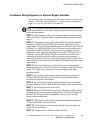
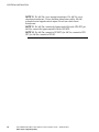
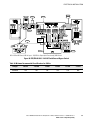
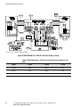
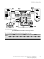
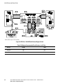
Installation Wiring Diagrams for External Bypass Switches
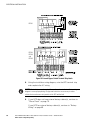
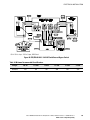
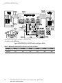
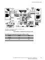
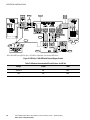
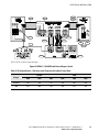
The following notes are referenced in the external bypass switch wiring
diagrams (Figure 34 through Figure 42). To determine which diagram is
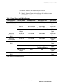
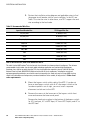
correct for your site, see Table 12 on page 53.
NOTE 1 The customer must provide input overcurrent protection as stated
in NEC Section 240-21 or local codes. Size the protection device according to
local code requirements.
NOTE 2 The UPS bypass switch/AC disconnect must be installed within
sight of the UPS. To properly install, complete the phase check starting on
page 75.
NOTE 3 The customer must provide and install this ground connection
according to NEC Sections 250-20(d), 250-30, 250-62, and 250-64 or local
requirements. This grounding electrode conductor must be at least #8 AWG
(8.36 mm@), per NEC table 250-66. If the UPS input circuit conductors are
larger than #8 AWG (8.36 mm @), aton requires the grounding electrode
conductor to be the same size (ampacity) as the largest UPS input circuit
conductor. Refer to NEC Section 110-3(b). Conduit is not considered an
acceptable grounding electrode conductor. aton does not recommend
routing the grounding electrode conductor through metallic conduit. This
conductor may require protection from physical damage according to local
requirements.
NOTE 4 All circuit conductors, including the neutral and equipment
grounding conductors, must be the same size (ampacity) and have the same
rating (75°C copper wire), and must be sized according to the input
protection device.
NOTE 5 The customer must provide output overcurrent protection as
stated in NEC Section 240-21 or local codes. Size the protection device
according to local code requirements.
NOTE 6 For maximum protection against electrical noise, use isolated
ground receptacles. Refer to NEC Section 250-146(d) or local requirements.
NOTE 7 Do not block air inlets and outlets.
NOTE 8 External UPS batteries are optional. The battery cable must not
be disconnected if a load is applied. Shut off the UPS before disconnecting
the cable. See “Battery Cabinet Installation” on page 21 for external
battery cabinet installation.
NOTE 9 UPS output circuits must be installed in dedicated conduit and
not shared with other electrical circuits.
NOTE 10 The load fuse or circuit breaker should be sized to match the
load current requirements.
NOTE 11 Connect to L1 for 208 Vac or L2 for 240 Vac.
Eaton FERRUPS Rack Mount UPS (850 VA–7 kVA) Installation Guide S 164201425 Rev 1
www.eaton.com/powerquality
57