1
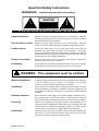
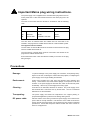
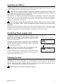
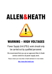
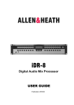
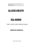
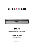
RPS14
Linear Console Power Supply
USER GUIDE
Publication AP5716
Limited One Year Warranty
This product has been manufactured in the UK by ALLEN & HEATH and is
warranted to be free from defects in materials or workmanship for a period of one
year from the date of purchase by the original owner.
To ensure a high level of performance and reliability for which this equipment has
been designed and manufactured, read this User Guide before operating.
In the event of a failure, notify and return the defective unit to ALLEN & HEATH or
its authorised agent as soon as possible for repair under warranty subject to the
following conditions:
Conditions Of Warranty
1. The equipment has been installed and operated in accordance with the
instructions in this User Guide
2. The equipment has not been subject to misuse either intended or accidental,
neglect, or alteration other than as described in the User Guide or Service
Manual, or approved by ALLEN & HEATH.
3. Any necessary adjustment, alteration or repair has been carried out by ALLEN
& HEATH or its authorised agent.
4. The defective unit is to be returned carriage prepaid to ALLEN & HEATH or its
authorised agent with proof of purchase.
5. Units returned should be packed to avoid transit damage.
In certain territories the terms may vary. Check with your ALLEN & HEATH agent
for any additional warranty, which may apply.
This product complies with the European Electromagnetic
Compatibility directives 89/336/EEC & 92/31/EEC and the
European Low Voltage Directives 73/23/EEC & 93/68/EEC.
Any changes or modifications to the power supply unit not approved by Allen
& Heath could void the compliance of the product and therefore the users
authority to operate it.
RPS14 User Guide AP5716 Issue 1.
Copyright © 2005 Allen & Heath. All rights reserved
Manufactured in the United Kingdom by Allen & Heath Limited
Kernick Industrial Estate, Penryn, Cornwall, TR10 9LU, UK
http://www.allen-heath.com
2
RPS14 User Guide
Important Safety Instructions
WARNINGS
- Read the following before proceeding :
CAUTION
ATTENTION: RISQUE DE CHOC ELECTRIQUE – NE PAS OUVRIR
Read instructions:
Retain these safety and operating instructions for future reference. Adhere to
all warnings printed here and on the power supply unit. Follow the operating
instructions printed in this User Guide.
Do not remove covers:
Operate the power supply unit with its covers correctly fitted. Refer any
service work on the power supply unit to competent technical personnel only.
Power sources:
Connect the power supply unit to a mains power supply only of the type
described in this User Guide and marked on the rear panel. Use only the
power cord with sealed mains plug appropriate for your local mains supply as
provided with the power supply unit. If the provided plug does not fit into your
outlet consult your service agent for assistance.
Power cord routing:
Route the power cord so that it is not likely to be walked on, stretched or
pinched by items placed upon or against it.
Grounding:
Do not defeat the grounding and polarisation means of the power cord plug.
Do not remove or tamper with the ground connection in the power cord.
WARNING: This equipment must be earthed.
Water and moisture:
To reduce the risk of fire or electric shock do not expose the power supply unit
to rain or moisture or use it in damp or wet conditions. Do not place
containers of liquid on it which might spill into any openings.
Ventilation:
Do not obstruct the ventilation slots or position the power supply unit where
the air flow required for ventilation is impeded. If the power supply unit is to
be operated in a flightcase ensure that it is constructed to allow adequate
ventilation.
Heat and vibration:
Do not locate the power supply unit in a place subject to excessive heat or
direct sunlight as this could be a fire hazard. Locate the power supply unit
away from any equipment which produces heat or causes excessive vibration.
Servicing:
Switch off the equipment and unplug the power cord immediately if it is
exposed to moisture, spilled liquid, objects fallen into the openings, the power
cord or plug become damaged, during lightening storms, or if smoke, odour or
noise is noticed. Refer servicing to qualified technical personnel only.
Installation:
Install the power supply unit in accordance with the instructions printed in this
User Guide. Do not connect the output of power supply unit to any other
equipment other than that specified by Allen & Heath.
RPS14 User Guide
3
Important Mains plug wiring instructions.
The power supply unit is supplied with a moulded mains plug fitted to the AC
mains power lead. Follow the instructions below if the mains plug has to be
replaced.
The wires in the mains lead are coloured in accordance with the following
code:
WIRE COLOUR
TERMINAL
European
USA/Canada
L
LIVE
BROWN
BLACK
N
NEUTRAL
BLUE
WHITE
E
EARTH GND
GREEN & YELLOW
GREEN
The wire which is coloured Green and Yellow must be connected to the
terminal in the plug which is marked with the letter E or with the Earth symbol.
This appliance must be earthed.
The wire which is coloured Blue must be connected to the terminal in the plug
which is marked with the letter N.
The wire which is coloured Brown must be connected to the terminal in the
plug which is marked with the letter L.
Ensure that these colour codes are followed carefully in the event of the plug
being changed.
Precautions
4
Damage :
To prevent damage to the power supply unit cosmetics, avoid placing heavy
objects on the unit, scratching the surface with sharp objects, or subjecting the
power supply unit to rough handling and vibration.
Environment :
Protect from excessive dirt, dust, heat and vibration when operating and
storing. Avoid tobacco ash, smoke, drinks spillage, and exposure to rain and
moisture. If the power supply unit becomes wet, switch off and remove power
immediately. Allow to dry out thoroughly before using again.
Cleaning :
Avoid the use of chemicals, abrasives or solvents. The power supply unit is
best cleaned with a soft brush and dry lint-free cloth. The use of electrical
lubricants is not recommended.
Transporting :
The power supply unit should be transported in the original packing or
purpose built flightcase to protect it from damage during transit.
DC power cable:
Plan the location of the mixing console and power supply unit so that the DC
power cable is not fully extended. Full extension of the cable can stress the
mixing console and power supply unit connectors and may result in undesired
performance. Ensure that the power cable is located such that it cannot be
stood on or tripped over.
RPS14 User Guide
Introduction
This user guide presents a quick reference to the RPS14. We recommend that you read this fully
before starting. Included is information on installing, connecting and operating the power supply
unit along with panel drawings and technical specification. Whilst we believe the information in this
guide to be reliable we do not assume responsibility for inaccuracies. We also reserve the right to
make changes in the interest of further product development.
We are able to offer further product support through our worldwide network of approved dealers
and service agents. You can also access our Web site (www.allen-heath.com) for information on
our company and its pedigree, our full product range and our design philosophy. To help us
provide the most efficient service please keep a record of your power supply unit serial number,
and date and place of purchase to be quoted in any communication regarding this product. The
serial number is located on the rear panel.
Check the Packing Contents
Retain the product packing should you need to ship the product in future.
components:
RPS14
You should find the following
1x RPS14 POWER SUPPLY UNIT. This is packed with its
rubber feet fitted. The feet can be removed for rack mounting.
ALLEN&HEATH
POWER ON
ON
OFF
HI TEMP
+/-17V
+12V
1x IEC MAINS LEAD with moulded plug. Check that the plug is
suitable for connection to your local mains supply.
+48V
CONSOLE PSU
AUTO COMBINING LINEAR TECHNOLOGY
RPS14/n Unit shipped as a spare. n = mains voltage
1x SHORT (0.75m) male>male DC POWER CABLE.
Part number 002-584. Connects the RPS14 as a backup to the
main console supply. Or:
+RPS14/n Unit shipped with console. n = mains voltage
1x LONG (2.9m) male>female DC POWER CABLE.
Part number 002-583. Connects the RPS14 to the mixing
console.
DOCUMENTATION including Safety Sheet AP3345, this user
guide AP5716 and the Registration Card AP3594.
The RPS14
The slimline RPS14 power supply unit is a high performance, low noise linear power supply producing DC
voltages by rectifying, smoothing and regulating AC voltages from the secondary windings of a mains transformer.
Allen & Heath mixing consoles employ a number of DC voltage supply levels in their operation and these are
provided at the output of the power supply unit. The RPS14 has a built in combiner for connection to a second
supply for backup. Full protection and thermal sensing fan cooling ensures the power supply unit will operate
consistently.
RPS14
ALLEN&HEATH
POWER ON
ON
OFF
+/-17V
HI TEMP
+48V
+12V
CONSOLE PSU
AUTO COMBINING LINEAR TECHNOLOGY
ALLEN&HEATH RPS14 CONSOLE PSU
DO NOT OBSTRUCT VENTILATION OPENINGS.
DO NOT OPEN. NO USER SERVICEABLE PARTS INSIDE.
THIS APPARATUS MUST BE EARTHED BY THE POWER CORD.
CAUTION
AVIS: RISQUE DE CHOC ELECTRIQUE - NE PAS OUVRIR.
DC POWER OUT 1
DC POWER IN (OUT 2)
WARNING: TO REDUCE THE RISK OF ELECTRIC SHOCK
DO NOT EXPOSE THIS APPARATUS TO RAIN OR MOISTURE.
CAUTION: FOR CONTINUED PROTECTION AGAINST RISK OF FIRE REPLACE FUSE
WITH SAME TYPE AND RATING. DISCONNECT SUPPLY BEFORE CHANGING FUSE.
ATTENTION: REMPLACER LE FUSIBLE AVEC UN DES MEMES CARACTERISTIQUES.
COUPER L'ALIMENTATION AVANT DE CHANGER LE FUSIBLE.
MAINS INPUT
V AC ~ 47- 63 Hz
525W MAX
CHASSIS
GROUND
FUSE
S/No
MADE IN ENGLAND
RPS14 User Guide
FUSE TYPE
AC SUPPLY
T10A L 250V 20mm
T8A L 250V 20mm
100-120V~
220-240V~
PIN 1 = +12V @ 5A
PIN 2 = +17V @ 8A
PIN 3 = CHASSIS GND
PIN 4 = A GND
PIN 5 = D GND
PIN 6 = +48V @ 500mA
PIN 7 = -17V @ 8A
TO CONSOLE
MAIN
COMBINING
SUPPLIES
REDUNDANT
5
Installation
Free standing
The RPS14 can be operated as a freestanding unit for shelf or floor operation. Ensure adequate air flow around
the unit. It must not be covered in any way. Always stand the unit on a firm flat surface well away from any soft
furnishings or carpet.
Rack mounting
The RPS14 is designed as a 19 inch rack mount unit and will occupy 2U (3.5 inches) of rack space. The fast feet
may need to be removed before rack mounting. Retain feet for future use.
An important consideration when rack-mounting the unit is the need for natural convection of airflow around the
unit. Good ventilation below the unit, in the floor or back of the rack, will ensure a continuous path for airflow.
Rack equipment known to produce a significant amount of heat should not be mounted directly below the power
supply unit. Equipment which also relies on good airflow within the rack (i.e. most power amplifiers and other
power supply units) should be given due consideration and some space should be provided between such units
and between the RPS14 unit. Forced convection, by means of a fan-tray, may be desirable in some situations.
Location
As with any power supply unit that contains a mains voltage transformer, it is preferable to provide a degree of
physical isolation of the unit from other equipment, particularly that which carries low level audio signals, to avoid
any possible interference pick-up. For this reason power supply units supplied with Allen & Heath ML series
mixing consoles are provided with a long (2.9m) output cable to enable them to be positioned away from the
mixing console. Backup power supply units, bought separately, are provided with a shorter (0.75m) output cable
to combine power supply units. For the same reason, when rack-mounting it is preferable to avoid locating the
unit next to signal processing equipment.
Earthing
Finally, some consideration should be given to the earthing arrangement of the system, at the centre of which is
the console and the RPS14. The console chassis is earthed to the mains earth via the power supply unit. When
rack-mounting the RPS14 care should be taken to avoid any possible “ground loops” in the system which may
introduce audible hum or buzz to otherwise clean audio signals. Ground loops occur where signal processing
equipment patched to the console, has its signal earth connected to the equipment chassis. A ground loop is
formed if the chassis of the signal processing equipment and the RPS14 chassis are in electrical contact through
the fixing rails they share in the rack. The RPS14 has audio 0V and mains earth connected internally.
Fitting in a rack
443mm (17.4")
The RPS14 is supplied ready for use free standing.
For rack mounting remove and retain the four rubber
feet.
Do not obstruct the ventilation slots.
Ensure adequate air flow around the RPS14.
Do not install the unit directly above or
below other equipment.
Do not remove the cover of the RPS14.
There are no user serviceable parts inside.
483mm (19")
RPS14
92mm
3.6"
310mm (12.2")
374mm (14.7")
ALLEN&HEATH
88mm
3.5"
2U
6
RPS14 User Guide
Operating the RPS14
The RPS14 is internally wired to operate from one of the following standard settings: 100V, 120V, 220V, or 240V.
The unit is shipped pre-wired for the country in which it is to be used.
Check that the rear panel is marked to indicate the voltage that is correct for your territory. The
power supply unit is provided with an IEC type mains connector and moulded mains plug. Check that
this is correct for connection to your wall socket outlet.
Switch the unit on by setting the front panel POWER ON switch to its ON position. The three front panel voltage
rail indicators (+/-17V, +12V, +48V) should light. The ‘HI TEMP’ indicator should be off during normal operation.
It lights to warn when the power supply unit is becoming too hot. Should that be the case, improve the ventilation
or lower the air temperatures around the unit.
To avoid audible thumps and bangs through the speakers, always turn the console on before
switching on the amplifier system, and turn the amplifiers off before switching off the console power
supply unit.
Always switch the power supply unit off before connecting or disconnecting the console power cables, removing
or installing console modules and any servicing work. In the event of an electrical storm, or large mains voltage
fluctuations, immediately switch off the power supply unit and disconnect from the mains supply.
Combining Power supply units
The RPS14 has a built-in combiner allowing direct connection to another
power supply unit for backup. It can be combined with either another
RPS14 or the alternative MPS14 power supply unit. Either can be used
as the main or backup supply.
Connect the two power supply units together using the DC link cable
provided by plugging into the DC sockets of each unit as shown below.
Note that the DC link cable can be connected to either of the two DC
output connectors on both units.
Avoid fully extending the DC cables when plugging in as this
may stress the cable and connectors resulting in failure.
Ensure that walkways, aisles and gangways are not obstructed by cables.
To console
DC cable 002-583
RPS14 or MPS14
DC link cable 002-584
BACKUP
RPS14 or MPS14
To ensure correct performance we recommend that you do not extend or
modify the DC power cable in any way.
Cleaning the Unit
The RPS14 does not use any internal filters. Air is drawn through the fan grille on the rear, blown through a
heatsink tunnel and out through ventilation slots in the front panel. It is not necessary to open the unit for
cleaning. Simply keep the fan and ventilation slots free of dust and dirt using a vacuum cleaner and dry, lint free
cloth. Do not use liquid cleaners or compressed air to clean the unit.
Always switch the unit off when inspecting or cleaning it.
RPS14 User Guide
7
Replacing the mains fuse
The AC mains fuse is located on the rear of the RPS14 unit next to the AC mains connector. In the event of a
mains surge or under-rated fuse value, the fuse will rupture. Switch off the power supply and remove the mains
lead plug from the “MAINS INPUT” socket on the rear of the unit. Check the fuse and replace if necessary. In the
event of repeated failure of the mains fuse, consult your Allen & Heath service agent.
In the unlikely event of an internal DC rail fuse failure, consult your Allen & Heath service agent or Allen & Heath
technical support.
TO AVOID THE RISK OF FIRE REPLACE FUSE WITH THE CORRECT TYPE ONLY, AS INDICATED
ON THE UNIT.
AC~ mains input voltage
Fuse type
A&H Part No.
100V – 120V ± 10%
T 10A 250V 20mm
AL3455
220V – 240V ± 10%
T 8A 250V 20mm
AL0487
Technical specification
Mains Input Voltage Range:
Internally wired for region:
100V +/- 10%
50/60Hz
120V +/- 10%
50/60Hz
220V +/- 10%
50/60Hz
240V +/- 10%
50/60Hz
Note: Contact Allen & Heath if your local mains voltage is not shown above.
Power consumption (max.)
650W
Mains Fuse:
100/120V
T10A 250V 20mm
A&H Part no:
AL3455
220/240V
T8A 250V 20mm
A&H Part no:
AL0487
PCB Ident
F1 (+17.5V)
F2 (-17.5V)
F3 (+48V)
Fuse type
T 16A 250V 20mm
T 16A 250V 20mm
T 1.6A 250V 20mm
A&H Part no:
A&H Part no:
A&H Part no:
AL8154
AL8154
AL0466
F4 (+12V)
T 6.3A 250V 20mm
A&H Part no:
AL0395
Internal Fuses:
DC Outputs:
DC Voltage Rail
+17 VOLTS
-17 VOLTS
+12 VOLTS
+48 VOLTS
Output Current
8A Max.
8A Max.
4A Max.
500mA Max.
Overall Dimensions:
Front Panel:
Chassis
Height including feet:
Depth:
Weight:
483mm x 88mm
443mm x 88mm
92mm
328mm
12kg
19 inch 2U
17.4 inches
3.6 inches
12.9 inches
26.4 lbs
Cable Assemblies:
Assembly
DC cable
DC LINK cable
8
Description
2.9m power supply to console cable assembly
0.75m backup supply to main supply cable assembly
A&H Part no:
002-583
002-584
RPS14 User Guide