1
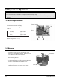
MICROWAVE OVEN
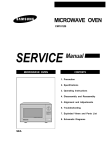
M1913 (WHITE/BLUE/BROWN)
SERVICE
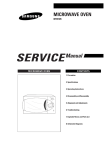
MICROWAVE OVEN
Manual
CONTENTS
1. Precaution
2. Specifications
3. Operating Instructions
4. Disassembly and Reassembly
5. Alignment and Adjustments
6. Troubleshooting
7. Exploded Views and Parts List
8. Wiring Diagram
1. Precaution
Follow these special safety precautions. Although the microwave oven is completely safe during ordinary
use, repair work can be extremely hazardous due to possible exposure to microwave radiation, as well as
potentially lethal high voltages and currents.
1-1 Safety precautions (
)
1. All repairs should be done in accordance
with the procedures described in this
manual. This product complies with
Federal Performance Standard 21 CFR
Subchapter J (DHHS).
2. Microwave emission check should be
performed to prior to servicing if the oven is
operative.
3. If the oven operates with the door open :
Instruct the user not to operate the oven and
contact the manufacturer and the center for
devices and radiological health immediatly.
4. Notify the Central Service Center if the
microwave leakage exceeds 5 mW/cm2
5. Check all grounds.
6. Do not power the MWO from a "2-prong"
AC cord. Be sure that all of the built-in
protective devices are replaced. Restore any
missing protective shields.
7. When reinstalling the chassis and its
assemblies, be sure to restore all protective
devices, including: nonmetallic control
knobs and compartment covers.
8. Make sure that there are no cabinet openings
through which people--particularly
children--might insert objects and contact
dangerous voltages. Examples: Lamp hole,
ventilation slots.
9. Inform the manufacturer of any oven found
to have emmission in excess of 5 mW/cm2,
Make repairs to bring the unit into
compliance at no cost to owner and try to
determine cause.
Instruct owner not to use oven until it has
been brought into compliance.
CENTRAL SERVICE CENTER
10. Service technicians should remove their
watches while repairing an MWO.
Samsung Electronics
11. To avoid any possible radiation hazard,
replace parts in accordance with the wiring
diagram. Also, use only the exact
replacements for the following parts:
Primary and secondary interlock switches,
interlock monitor switch.
12. If the fuse is blown by the Interlock Monitor
Switch: Replace all of the following at the
same time: Primary, door sensing switch
and power relay, as well as the Interlock
Monitor Switch. The correct adjustment of
these switches is described elsewhere in this
manual. Make sure that the fuse has the
correct rating for the particular model being
repaired.
13. Design Alteration Warning:
Use exact replacement parts only, i.e.,
only those that are specified in the
drawings and parts lists of this manual.
This is especially important for the
Interlock switches, described above.
Never alter or add to the mechanical or
electrical design of the MWO. Any design
changes or additions will void the
manufacturer's warranty.10.Always unplug
the unit's AC power cord from the AC
power source before attempting to
remove or reinstall any component or
assembly.
14. Never defeat any of the B+ voltage
interlocks. Do not apply AC power to the
unit (or any of its assemblies) unless all
solid-state heat sinks are correctly installed.
15. Some semiconductor ("solid state") devices
are easily damaged by static electricity. Such
components are called Electrostatically
Sensitive Devices (ESDs). Examples include
integrated circuits and field-effect
transistors.
Immediately before handling any
semiconductor components or assemblies,
drain the electrostatic charge from your
body by touching a known earth ground.
16. Always connect a test instrument's ground
lead to the instrument chassis ground before
connecting the positive lead; always remove
the instrument's ground lead last.
1-1
Pretaution
1-2 Special Servicing Precautions (Continued)
17. When checking the continuity of the witches
or transformer, always make sure that the
power is OFF, and one of the lead wires is
disconnected.
18. Components that are critical for safety are
indicated in the circuit diagram by
shading,
or
.
19. Use replacement components that have the
same ratings, especially for flame resistance
and dielectric strength specifications. A
replacement part that does not have the
same safety characteristics as the original
might create shock, fire or other hazards.
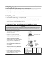
1-3 Special High Voltage Precautions
1. High Voltage Warning
Do not attempt to measureany of the high
voltages--this includes the filament voltage
of the magnetron. High voltage is present
during any cook cycle.
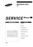
Before touching any components or wiring,
always unplug the oven and discharge the
high voltage capacitor (See Figure 1-1)
2. The high-voltage capacitor remains charged
about 30 seconds after disconnection. Short
the negative terminal of the high-voltage
capacitor to to the oven chassis. (Use a
screwdriver.)
3. High voltage is maintained within specified
limits by close-tolerance, safety-related
components and adjustments. If the high
voltage exceeds the specified limits, check
each of the special components.
Fig. 1-1. Discharging the High Voltage Capacitor
1-2
Samsung Electronics
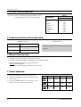
2. Specifications
2-1 Table of Specifications
MODEL
M1913
POWER SOURCE
230V 50Hz, SINGLE PHASE
POWER CONSUMPTION
1,400W
OUTPUT POWER
100W/1000W (IEC-705)
OPERATING FREQUENCY
2450MHz
COOLING METHOD
COOLING FAN MOTOR
MAGNETRON
OM75P(31)
OUTSIDE DIMENSIONS
517(W) x 297(D) x 379(H)mm
OVEN CAVITY DIMENSIONS
366(W) x 241(D) x349(H)mm
SHIPPING WEIGHT
APPROX. 16 Kg
Samsung Electronics
2-1
3. Operating Instructions
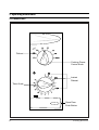
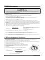
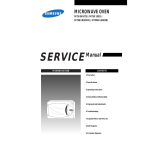
3-1 Control Panel
Defrost
Cooking Power
Control Knob
Instant
Reheat
Timer Knob
Open Door
Push Button
3-1
Samsung Electronics
Operating Instruction
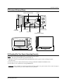
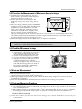
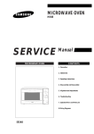
3-2 Features & External Views
VENTILATION HOLES
LIGHT
ROLLER RING
TURNTABLE
DOOR
LATCHES
COUPLER
SAFETY
INTERLOCK HOLES
297mm
DOOR
OPEN DOOR
PUSH BUTTON
241mm
336mm
517mm
379mm
3-3 Checking That Your Oven is Operating Correctly
NOTE: The oven must be plugged into an appropriate wall socket.
The glass plate must be in position in the ovn.
1. Open the oven door by pushing the OPEN DOOR button. Place a glass of water on the glass plate.
Close the door.
2. Set the power level to 100%(maximum) by turning COOKING POWER CONTROL knob.
3. Set the time to 4 to 5 minutes by turing TIMER knob.
Important: If any problem is experienced in the operation of the oven, please refer to the section on page 4
"what to do if you are in doubt or have a problem."
Samsung Electronics
3-2
Operating Instruction
3-4 Variable Power Cooking Chart
Operation: Set the COOKING POWER CONTROL knob
to the appropriate power level by turning it.
OUTPUT
POWER LEVEL
M1933
FULL
HIGH
REHEAT
MEDIUM HIGH
MEDIUM
MEDIUM LOW
DEFROST
LOW
1000W
850W
700W
600W
450W
300W
180W
100W
3-5 Adjusting the Cooking Time During Cooking
Stopping the Cooking
To stop the cooking....
Press....
Temporarily
Open Door.
To resume cooking, close the door.
Completely
Adding Extra Time
Simply move the timer knob to any increased setting that
you require.
Turn the TIMER knob to 'O'
3-6 Manual Defrosting Food
1. Place the frozen food in the oven and close the door.
2. Turn the COOKING POWER CONTROL knob to Defrost symbol.
3. Turn the TIMER knob to select appropriate time.
Result: Defrosting begins.
When Defrosting has finished, the oven beeps.
3-7 Instant Cook Guide
1. Place the food in the oven and close the door.
2. Turn the COOKING POWER CONTROL knob
to Max Power.
3. Turn the TIMER knob to select instant cook,
drinks, soup/sauce and fresh vegetables.
3-3
Symbol
Recipes
Serving Size Power level Standing Time
Drink
150 mL
100%
1~2mins.
Soup/
Sauce
200~250
ml
100%
2~3mins.
Fresh/
Vegetables
300~350
g
100%
3mins.
Samsung Electronics
4. Disassembly & Reassembly
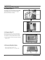
4-1 Replacement of Magnetron, Motor Assembly and Lamp
Remove the magnetron including the shield case,
permanent magnet, choke coils and capacitors (all
of which are contained in one assembly).
Lamp
Cover Air
Thermo S/W
1. Disconnect all lead wires from the magnetron
and lamp.
2. Remove a screw securing the magnetron
supporter.
3. Remove the magnetron supporter.
4. Remove the air cover.
5. Remove screws securing the magnetron to the
wave guide.
6. Take out the magnetron very carefully.
7. Remove screws from the back panel.
8. Take out the fan motor.
9. Remove the oven lamp by rotating to pull out
from hole of air cover.
Fan Motor
Screw
Magnetron
H. V. Capacitor
H. V. Trans
NOTE1: When removing the magnetron, make sure that its antenna does not hit any adjacent parts, or it
may be damaged.
NOTE2: When replacing the magnetron, be sure to remount the magnetron gasket in the correct position
and make sure the gasket is in good condition.
4-2 Replacement of High Voltage Transformer
1. Discharge the high voltage capacitor.
2. Disconnect all the leads.
3. Remove the mounting bolts.
4. Reconnect the leads correctly and firmly.
H. V. Trans
Screws
Samsung Electronics
4-1
Disassembly & Reassembly
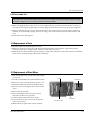
4-3 Replacement of Door Assembly
4-3-1 Removal of Door "C"
Insert flat screwdriver into the gap between Door
"A" and Door "C" to remove Door "C". Be careful
when handling Door "C" because it is fragile.
Then remove the door assembly.
Door "A"
Door "C"
4-3-2 Removal of Door "E"
Following the procedure as shown in the figure,
insert and bend a thin metal plate between Door
"E" and Door "A" until you hear the 'tick' sound.
¥ Insertion depth of the thin metal plate should be
0.5mm or less.
4-3-3 Removal of Key Door & Spring
Remove pin hinge from Door "E"
Detach spring from Door "E" and key door.
Door "E"
4-2
Key Door
Spring
Samsung Electronics
Disassembly & ReaAssembly
4-3-5 Reassembly Test
After replacement of the defective component parts of the door, reassemble it and follow the instructions below for proper
installation and adjustment so as to prevent an excessive microwave leakage.
1. When mounting the door to the oven, be sure to adjust the door parallel to the bottom line of the oven
face plate by moving the upper hinge and lower hinge in the direction necessary for proper alignment.
2. Adjust so that the door has no play between the inner door surface and oven front surface. If the door
assembly is not mounted properly, microwave energy may leak from the space between the door and
oven.
3. Do the microwave leakage test.
4-4 Replacement of Fuse
1. Disconnect the oven from the power source.
2. When 15A fuse blows out by the operation of interlock monitor switch failure, replace the primary
interlock switch, door sensing switch, monitor switch and power relay.
3. When the above three switches operate properly, check if any other part such as the control circuit board,
blower motor or high voltage transformer is defective.
4-5 Replacement of Drive Motor
1. Take out the glass tray, guide roller and coupler
from cavity.
Screw
2. Turn the oven upside down to replace the drive motor.
Drive Motor
3. Remove a screw securing the drive motor cover.
4. Disconnect all the lead wires from the drive motor.
5. Remove screws securing the drive motor to the
cavity.
6. Remove the drive motor.
7. When replacing the drive motor, be sure to
remount it in the correct position.
8. Connect all the leads to the drive motor.
9. Screw the deive motor cover to the base plate
with a screw driver.
Base Plate
Drive Motor Cover
10. Remount the coupler in the correct position.
Samsung Electronics
4-3
5. Alignment and Adjustments
PRECAUTION
1. High voltage is present at the high voltage terminal of the high voltage transformer during any cook cycle.
2. It is neither necessary nor advisable to attempt measurement of the high voltage.
3. Before touching any oven components, or wiring, always unplug the oven from its power source and discharge the high voltage
capacitor.
5-1 High Voltage Transformer
1. Remove connectors from the transformer
terminals and check continuity.
2. Normal resistance readings should be as
follows:
Secondary
Filament
Primary
Approx. 100W
Approx.0W
Approx.1.450W
Filament Terminals
Secondary Terminal
Primary
Terminals
(Room temperature = 20˚C)
5-2 Magnetron
1. Continuity checks can only indicate an open
filament or a shorted magnetron. To diagnose an
open filament or shorted magnetron.
Magnetron Antenn
Gasket Plate
2. Isolate the magnetron from the circuit by
disconnecting its leads.
3. A continuity check across the magnetron filament
terminals should indicate one ohm or less.
4. A continuity check between each filament terminal
and the magnetron case should read "open".
5-1
Cooling Fins
Samsung Electronics
Alignment and Adjustments
5-3 High Voltage Capacitor
1. Check continuity of the capacitor with meter set at the highest ohm scale.
2. Once the capacitor is charged, a normal capacitor shows continuity for a short time, and then
indicates 10MW.
3. A shorted capacitor will show continuous continuity.
4. An open capacitor will show constant 10MW.
5. Resistance between each terminal and chassis should read infinite.
5-4 High Voltage Diode
1. Isolate the diode from the circuit by disconnecting its leads.
2. With the ohm-meter set at the highest resistance scale, measure the resistance across the diode
terminals. Reverse the meter leads and read the resistance. A meter with 6V, 9V or higher voltage
batteries should be used to check the front-to back resistance of the diode, otherwise an infinite
resistance may be read in both directions. The resistance of a normal diode will be infinite in one
direction and several hundred KW in the other direction.
5-5 Adjustment of Primary Switch, Secondary Switch and Monitor Switch
Precaution
For continued protection against radiation hazard, replace parts in accordance with the wiring diagram and be sure to use the
correct part number for the following switches.: Primary and secondary interlock switches and the interlock monitor switch all
together. Then follow the adjustment procedures below. After repair and adjustment, be sure to check the continuity of all
interlock switches and the interlock monitor switch.
1. When mounting Primary switch and
Interlock Monitor switch to Latch Body,
consult the figure below.
Primary Interlock Switch
2. NOTE: No specific adjustment during
installation of Primary switch and Monitor
switch to the latch body is necessary.
3. When mounting the Latch Body to the oven
assembly, adjust to the Latch Body by
moving it so that the oven door will not have
any play. Check for play in the door by
pulling the door assembly. Make sure that
the latch keys move smoothly after
adjustment is completed. Completely tighten
the screws holding the Latch Body to the
oven assembly.
4. Reconnect to Monitor switch and check the
continuity of the monitor circuit and all latch
switches again by following the components
test procedures.
5. Confirm that the gap between the switch
housing and the switch actuator is no more
than 0.5mm when door is closed.
Samsung Electronics
Interlock
Monitor
Switch
Lever Door
SECONDARY
Switch
Body Latch
Primary switch
Monitor switch (COM-NC)
Monitor switch (COM-NO)
Secondary switch
Door Open
Door Closed
¥
0
¥
¥
0
¥
0
0
5-2
Alignment and Adjustments
5-6 Output Power of Magnetron
CAUTION
MICROWAVE RADIATION
PERSONNEL SHOULD NOT ALLOW EXPOSWRE TO MICROWAVE RADIATION FROM MICROWAVE GENERATOR OR
OTHER PARTS CONDUCTING MICROWAVE ENERGY.
The output power of the magnetron can be measured by performing a water temperature rise test.
Equipment needed
* Two 1-liter cylindrical borosilicate glass vessel (Outside diameter of 190mm)
* One glass thermometer with mercury column
NOTE: Check line voltage under load. Low voltage will lower the magnetron output. Make all
temperature and time tests with accurate equipment.
1. Fill the one liter glass vessel with one liter of water.
2. Stir water in glass vessel with thermometer and record glass vessel's temperature as T1. (10±1ûC)
3. After moving the water into another glass vessel, place it on the center of the cooking tray. Set the oven
to high power and operate for 45 seconds exactly. (2 seconds included as a holding time of magnetron
oscillation)
4. When heating is finished, stir the water again with the thermometer and measure the temperature rise as T2.
5. Subtract R1 from T2. This will give you the water temperature rise. (DT)
6. The output power is obtained by the following formula;
Output Power =
4.187 x 1000 x DT
42
42 : Heating Time (sec) * Output (W) = 100 x DT
4.187 : Coefficient for Water
1000 : Water (cc)
DT : Temperature Rise (T2-T1)
7. Normal temperature rise for this model is 9ûC to 11ûC at 'HIGH'.
NOTE 1: Variations or errors in the test procedure will cause a variance in the temperature rise.
Additional power test should be made if temperature rise is marginal.
NOTE 2: Output power in watts is computed by multiplying the temperature rise (step E) by a power
factor of 91 in case of centigrade temperature.
5-7 Microwave Heat Distribution - Heat Evenness
The microwave heat distribution can be checked indirectly by measuring the water temperature risen at
certain positions in the oven :
1. Prepare five beakers made of 'Pyrex', having 100 milliliters capacity each.
2. Measure exactly 100milliliters off water load with a measuring cylinder and pour it into each beaker.
3. Measure the temperature of each water load.
(Readings shall be taken to the first place of decimals.)
4. Put each beaker in place on the cooking tray as illustrated in figure
below and start heating.
D
Beaker
5. After heating for 2 minutes, measure the temperatures of water in
D
each beaker.
6. Microwave heat distribution rate can be caicviated as follows :
Heat Distribution =
Minimum
Temperature Rise
Maximum
Temperature Rise
D/4
D/4
D/4
X 100(%)
D/4
Cooking Tray
The result should exceed 65%.
5-3
Samsung Electronics
Alignment and Adjustments
5-8 Procedure for Measurement of Microwave Energy Leakage
1) Pour 275±15cc of 20±5ûC(68±9ûF) water in a
beaker which is graduated to 600cc, and place
the beaker in the center of the oven.
2) Start to operate the oven and measure the
leakage by using a microwave energy survey
meter.
3) Set survey meter with dual ranges to 2,450MHz.
4) When measuring the leakage, always use the 2
inch spacer cone with the probe. Hold the probe
perpendicular to the cabinet door. Place the
spacer cone of the probe on the door and/or
cabinet door seam and move along the seam,
the door viewing window and the exhaust
openings moving the probe in a clockwise direction at a rate of 1 inch/sec. If the leakage testing of the
cabinet door seam is taken near a corner of the door, keep the probe perpendicular to the areas making
sure that the probe end at the base of the cone does not get closer than 2 inches to any metal. If it gets
closer than 2 inches, erroneous readings may result.
5) Measured leakage must be less than 4mW/cm2, after repair or adjustment.
Maximum allowable leakage is 5mW/cm2.
4mW/cm2 is used to allow for measurement and meter accuracy
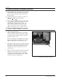
5-9 Check for Microwave Leakage
1. Remove the outer panel.
2. Pour 275±15cc of 20±5ûC(68±9ûF) water in a
beaker which is graduated to 600cc, and
place the beaker in the center of the oven.
3. Start the oven at the highest power level.
4. Set survey meter dual ranges to 2,450MHz.
5. Using the survey meter and spacer cone as
described above, measure arnear the
opening of magnetron, the surface of the air
guide and the surface of the wave guide as
shown in the following photo.( but avoid the
high voltage components.) The neading
should be less than 4mW/cm2.
5-10 Note on Measurement
1) Do not exceed the limited scale.
2) The test probe must be held on the grip of the handle, otherwise a false reading may result when the
operator's hand is between the handle and the probe.
3) When high leakage is suspected, do not move the probe horizontally along the oven surface; this may
cause damage to the probe.
4) Follow the recommendation of the manufacturer of the microwave energy survey meter.
5-11 Leakage Measuring Procedure
5-13-1 Record keeping and notification after measurement
1) After adjustment and repair of a radiarion preventing device, make a repair record for the measured
values, and keep the data.
2) If the radiation leakage is more than 4 mW/cm2 after determining that all parts are in good condition,
functioning properly and the identical parts are replaced as listed in this manual notift that fact to ;
CENTRAL SERVICE CENTER
5-13-2 At least once a year have the microwave energy survey meter checked for accuracy by its
manufacturer.
Samsung Electronics
5-4
6. Troubleshooting
WARNING FOR HIGH VOLTAGE
4000 VOLTS EXIST AT THE HIGH VOLTAGE AREA. DO NOT OPERATE THE OVEN WITH CABINET PARTS REMOVED. DO NOT
REMOVE THE CABINET PARTS IF THE POWER SUPPLY CORD IS PLUGGED IN THE WALL OUTLET. UNPLUG THE POWER CORD
BEFORE SERVICING.
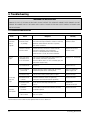
6-1 Electrical Malfunction
Parts
Fuse blows
out when
door is
opened.
Fuse is
open.
Oven lamp
does not
light.
Fan does
not operate.
Cause
Diagnosis
Remedy
Defective primary
interlock switch
ary winding.
Check continuity of the primary switch terminals with
wire removed using a multimeter. If there is continuity
between switch terminals when door is opened,
the switch is defective.
Replace the primary
interlock switch
Defective interlock
monitor switch
Check continuity of the monitor switch terminals
with wire removed by using a multimeter.
If there is continuity between switch terminals
when the door is closed, the switch is defective.
Replace the interlock
monitor switch
Layer short of the
secondary coil of
H. V. Transformer
The fuse will not blow right away, but if it blows in a
few seconds, then there is a layer short.
If the fuse blows with H. V. Trans secondary open, the
transformer may be faulty.
Replace H. V. Transformer
1) Fuse blown out
Check fuse.
Replace the fuse.
2) Poor contact of
power cord
Check continuity of power supply cord. Also check
whether the power cord is securely wired.
Adjust or replace the
power supply cord.
3) Defective lamp
The fan motor rotates, but lamp does not light.
Replace the lamp.
4) Defective timer
contacts
Check the terminals of timer for continuity,
turning the timer knob ON and OFF repeatedly.
Replace the timer.
5) Thermal cutout
S/W open
In this case the oven lamp and fan do not
turn on
Replace the
thermal cutout S/W
1) Defective
fan motor.
If 220~230V is found at motor terminals, the motor
should be replaced.
Replace the motor.
2) Defective contacts of timer
The oven lamp does not light and fan motor
does not operate.
Replace the timer.
NOTE: Interlock monitor switch must be replaced when the fuse is blown out.
6-1
Samsung Electronics
Troubleshooting
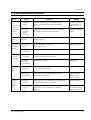
6-1 Electrical Malfunction (Continved)
Parts
Cause
Diagnosis
Remedy
1) Too small
a load
If a small amount of food is heated for a long time,
period of microwave may turn off during operation.
To increase the oven
load, add a glass of
water into the oven.
2) Defective
magnetron
thermal
cutout S/W
Check to see if the magnetron thermal cutout switch is
activated at a temperature higher than 150˚C.
Replace thermal cutout
switch.
Electric
shock is
felt.
Incomplete
qrounding
Make sure that qrounding of the power supply cord has
been done properly.
Rewire.
Door does
not operate
properly
1) Broken door
hinges
Remove the cabinet for inspection.
Check the door hinge.
Replace door hinges.
2) Missing or
loose screw
Check if the screws are secured well to the door hinge.
Fasten or tighten.
1) Defective
timer motor
If the timer does not operate with 220~230V applied to the
terminals, the timer motor amy be faulty.
Replace timer.
2) Defective
contacts
of timer S/W
The lamp does not light.
Replace timer
1) Defective
drive motor
Check to see if 21V exists at the motor terminals.
If so, motor will be defective.
Replace drive motor.
1) Blocking of
the ventilatior
Check if the air inlet or outlet ventilation is blocked
by the wall or other objects.
Keep a distance of
100mm from the
wall or the objects.
2) Defective
fan motor
If the fan motor does not operate with 220~230V applied
to the terminal, the motor may be faulty.
Replace fan motor.
3) Too small a
load or no
load
If a small amount of food is heated repeatedly over
a long period of time, microwave turns off during
operation.
To increase the oven
load, place a glass of
water into the oven.
Microwave
turns off
during cooking cycle.
Timer does
not operate.
Cooking tray
does not
rotate.
Magnetron
thermal
cutout
switch
OFF
Samsung Electronics
6-2
Troubleshooting
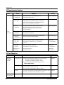
6-2 Unsatisfactory Cooking
Parts
-
Food is
not heated.
Cause
Diagnosis
Remedy
1) Open cathode
of magnetron
Check the terminals with a multimeter to see
if the heater circuit is open.
Replace magnetron.
2) Defective
H. V. Diode
Check the H. V. Diode for continuity in the reverse and
normal directions using megger. If there is continuity
in the reverse direction, the H. V. Diode may be faulty.
(In this event H. V. Capacitor will be hot)
Replace H. V. Diode.
3) Shorted
magnetron
Connect megger leads to quick-connect terminal &
body of the magnetron if there is continuity, the
magnetron may be faulty. (In this case the main
fuse will be blown)
Replace magnetron.
4) Defective
magnetron
If there is a crack in the magnetron antenna (dome),
the magnetron is defective.
Replace magnetron.
5) Poor contact
of primay
interlock switch
Check if the screws are secured well to the door hinge.
and pressing it ON and OFF repeatedly.
Replace or adjust.
6) Open coil of
H. V. Transformer
Check the continuity of primary coil and secondary
coil. If there is no continuity, H. V. Transformer is
defective.
Replace the
H. V. Transformer.
7) Shorted H. V.
capacitor
Check the continuity of capacitor.
If the capacitor shorts, the fuse blows
Replace the
H. V. Capacitor.
8) Monitor fuse
blown out
Check the monitor fuse
(on the noise filter)
Replace the
Monitor fuse
6-3 Part Check List
Symptom
Microwave
cooking does
not work.
Fan motor
does not rotate.
6-3
Related Parts
Check Points
Remedy
H.V.Transformer
1) Check if the primary and secondary coil is open or shorted.
* Resistance of primary coil: Approx. 2.30 Ω
Resistance of secondary coil: Approx. 123 Ω
2) Check if the MGT Heater Voltage is approx. 3.3V AC.
Caution : High voltage !
Replace.
H.V.Capacitor
Check continuity of capacitor between two
terminals with H.V.wire lead removed.
The resistance should be approx. 10MW, it's failure.
Replace.
H.V.Diode
1) If there is no continuity in forward, direction the H.V.Diode is open.
2) If there is continuity in reverse direction, it's shorted.
Replace.
Fan motor
Check if the motor coil is open.
Replace.
Samsung Electronics
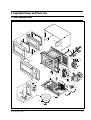
7. Exploded Views and Parts List
7-1 Main Exploded View
D3
D4
D2
D1
M1
M2
M3
M4
D6
D5
M31
M30
M5
M25
M23
M6
M14
M24
M9
B2
B3
M21
M13
M22
B4
M26
B1
M15
C5
C6
M8
M7
M17
C4
M12
M16
M18
M19
C3
C7
M10
C2
M27
M20
C1
M28
M29
Samsung Electronics
7-1
Exploded Views and Parts List
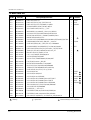
7-2 Main Parts List
Ref. No.
Parts No.
M1
M1
M1
M2
M3
M4
M5
M6
M8
M9
M10
M12
M13
M14
M15
M16
M17
M18
M19
M20
M21
M22
M23
M24
M25
M25
M25
M26
M26
M26
M27
M28
M29
M30
M31
M32
DE70-00011A
DE70-30134G
DE70-30001M
DE63-90035G
DE39-20145C
DE39-00013A
DE96-00008A
DE31-00002B
DE03-30035A
DE96-00005A
4713-001004
DE71-60458A
DE63-90062B
DE66-90113A
DE26-00008A
DE61-50106A
2501-001019
DE91-70063A
DE91-70061A
DE61-50579A
DE31-10154A
DE80-10001F
DE47-20173A
DE71-00015A
DE94-00078A
DE94-00078B
DE94-00078C
DE94-00184B
DE94-00184D
DE94-00184C
DE74-20015B
DE92-90189P
DE67-60081A
3601-000448
3601-001126
DE27-10020C
: Warning
7-2
Description/Specification
Q'ty
PANEL-OUTER;3RD-1.0
PANEL-OUTER;SECC,T0.6,-,-,BLUE,M1913-B
PANEL-OUTER;C/STEEL,T0.6,W360,L1128,BRN
CUSHION-RUBBER;DFA20,T2,W190,L100,BLK
ASSY POWER CORD;EP-48 1.0,-,-,-,-,GRY
WIRE HARNESS-A;230V50HZ,-,-,M1913/12,D,INRUSH
ASSY NOISE FILTER;SN-3WEB,250V10A,3W INRUSH D
MOTOR-FAN;SMF-3RDEA1,-,230V50HZ,2350RPM,CE2933
MAGNETRON;OM75PH((31)ESS
ASSY BODY LATCH;MW7896W,3RD-W,WONWOO,PP(FB53WH),P/BUTTON
LAMP-INCANDESCENT;230V,-,40W,ORG,-,-,25x71mm
COVER-AIR;PP(TB53),78G,-,-,WHT,3RD-1.0/1.3 MW5896W
CUSHION-RUBBER DOOR;RUBBER(CR),T12,W30,L50,HS60,M2
LEVER-DOOR;PP(TB53-GH10),T2.5,W31X100.5,-,12G,NTR,3RD-W
TRANS-H.V;SHV-293EC,230V50HZ,2230V/3.15V,-,DY
BRACKET-HVC;SECC,T0.8,W31,L125.8
C-OIL;1.10uF,2100V,BK,35X54X90,20mm
ASSY-HVD;V2M6,PI9.0,0.05MT
ASSY-H.V.FUSE;THV060T-0800-H,5KV/0.8A,WHT
FOOT;PP,H8,PI15.8x16.1,-,BLK,3RD
MOTOR-DRIVE;M2HJ49ZR02,ST-16,50/60HZ
BASE-PLATE;SGCC,T0.8,W345,L565,MW5896W
THERMOSTAT;PW-2N(90/60)30,187Y,250V7.5A,9
COVER-CEILING;T0.3,W114.2,L121.5,-,CE2933
ASSY DOOR;M1933
ASSY DOOR;M1933B,BLUE
ASSY DOOR;M1913-M,BROWN
ASSY CONTROL-BOX;230V50HZ,M1913/XEF,P/WHT
ASSY CONTROL-BOX;230V50HZ,M1913-B,BLUE
ASSY CONTROL-BOX;230V50HZ,M1913-M,BROWN
TRAY-COOKING;GLASS,T6.0,PI318,1050G,MW5630T
ASSY-GUIDE ROLLER;MW5896W
COUPLER;PPS,-,-,-,3RD-1.0/1.3
FUSE-FERRULE;250V,10A,SLOW-BLOW,CERAMIC,6.3
FUSE-FERRULE;250V,1.6A,QUICK-ACTING,CERAMIC
COIL-CHOKE;TC-104,0.9UH*2,-,L31*W20*H32,-,ABS,AC250V/14
: Option Parts
1
1
1
1
1
1
1
1
1
1
1
1
1
1
1
1
1
1
1
2
1
1
1
1
1
1
1
1
1
1
1
1
1
1
1
1
Remarks
WHITE
BLUE
BROWN
CV/AIR
HVT
WHITE
BLUE
BROWN
WHITE
BLUE
BROWN
: Electrostatically Sensitive Devices
Samsung Electronics
Exploded Views and Parts List
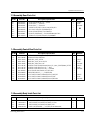
7-3 Assembly Door Parts List
Ref. No.
Parts No.
D1
D1
D1
D2
D3
D4
D5
D6
DE64-40326C
DE64-40326J
DE64-40326E
DE67-20187A
DE94-00073B
DE64-40012A
DE64-40006F
DE61-70032A
Description / Specification
DOOR-A;ABS(HR0370),T2.0,-,-,-,M1933
DOOR-A;ABS,-,-,-,-,M1913-B
DOOR-A;ABS,-,-,-,-,M1913-M
SCREEN-DOOR;SAN,T2.2,W377,L258,CLEAR,3RD-1
ASSY DOOR-SUB;3RD-1.0,MW5897G,BLK
DOOR-C;RESIN-PP(TB53),T2.0,CE945GF,BL
DOOR-KEY;POM(F20-02),-,-,12G,BLK,MW7897G,NO-TALK
SPRING-KEY;ES,HSWR,PI0.6,D5.4,L25,MW8640T
Q'ty
Remarks
1
1
1
1
1
1
1
1
WHITE
BLUE
BROWN
7-4 Assembly Control Box Parts List
Ref. No.
Parts No.
C1
C2
C3
C3
C3
C4
C4
C4
C5
C6
C7
C7
C7
DE66-20281A
DE61-70076A
DE64-10162A
DE64-10162C
DE64-10162B
DE72-70215B
DE72-70215D
DE72-70215C
3501-000309
DE45-00002A
DE94-00182B
DE94-00182D
DE94-00182C
Description / Specification
Q'ty
BUTTON-PUSH;ABS,15g,T2x37x86,WHT,3RD-W B D
SPRING-BUTTON;HSWR,PI0.6
KNOB;ABS,-,WHT,-,3RD-W
KNOB;ABS,-,BLUE,-,M1713-B/XEG
KNOB;ABS,-,BRN,-,M1713-M
CONTROL-PANEL-D;ABS(HR0370U),M1913,T2,-,L284,-,P/WHT(W9501),D-TYPE
CONTROL-PANEL;ABS,M1913-B,-,-,-,-,BLUE
CONTROL-PANEL;ABS,M1913-M,-,-,-,-,BROWN
RELAY-POWER;240V,3750VA,15A,-,6mS,20mS
TIMER;TMFK35M1A1,-,-,-,-,-,21V50HZ,CM0
ASSY CONTROL-PANEL;230V50HZ,M1913,P/WHT,XEF
ASSY CONTROL-PANEL;230V50HZ,M1913-B,BLUE
ASSY CONTROL-PANEL;230V50HZ,M1913-M,BROWN
1
1
2
1
1
1
1
1
1
1
1
1
1
Remarks
WHITE
BLUE
BROWN
WHITE
BLUE
BROWN
WHITE
BLUE
BROWN
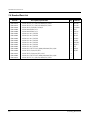
7-5 Assembly Body Latch Parts List
Ref. No.
Parts No.
B1
B2
B3
B4
DE66-40001C
3405-001034
3405-001032
DE66-90114A
Samsung Electronics
Description / Specification
LATCH-BODY;PP(FB53WH),-,39.2G,NTR,-,3RD-W MW5592W
SWITCH-MICRO;125/250VAC,16A,200GF,SPST-NO
SWITCH-MICRO;125/250VAC,16A,200GF,SPDT
LEVER-S/W;PP(FB53WH),-,-,-,3.5G,NTR,3RD-W MW5592W,-
Q'ty
Remarks
1
2
1
1
7-3
Exploded Views and Parts List
7-6 Standard Parts List
7-4
Parts No.
Description / Specification
Q'ty
DE60-10012A
DE60-10012A
DE60-10059A
DE60-10080A
DE60-10080A
DE60-10082H
DE60-10082H
DE60-10082H
DE60-10082H
DE60-10082H
DE60-10082H
DE60-10082H
DE60-10098A
DE60-10069A
DE60-10072A
DE60-10098A
DE60-10012A
SCREW-TAP TITE;TH,+,3,M4,L10,SWR10,ZPC2,TOOTH
SCREW-TAP TITE;TH,+,3,M4,L10,SWR10,ZPC2,TOOTH
SCREW-TAP TH;TH,M4,L8,SUS410,CR
SCREW-WASHER;M5,L12,2S
SCREW-WASHER;M5,L12,2S
SCREW-A;2S-4X12,TOOTHED
SCREW-A;2S-4X12,TOOTHED
SCREW-A;2S-4X12,TOOTHED
SCREW-A;2S-4X12,TOOTHED
SCREW-A;2S-4X12,TOOTHED
SCREW-A;2S-4X12,TOOTHED
SCREW-A;2S-4X12,TOOTHED
SCREW-ASSY TAP TITE;PH,TC,M4X8,SWRCH18A,ZPC2,GLD,W
SCREW-TAP TH;TH,M4,L10,FRFZY
SCREW-TAP TH;TH,M4,L16,FEFZY,2-SLOT
SCREW-ASSY TAP TITE;PH,TC,M4X8,SWRCH18A,ZPC2,GLD,W
SCREW-TAP TITE;TH,+,3,M4,L10,SWR10,ZPC2,TOOTH
1
1
2
4
4
3
2
2
1
2
5
2
2
1
4
1
1
Remarks
N/F-EAR
P/C-EAR
C/CEILING
MGT
TNS-HV
B-PLTE
BD-LAT
CN-BOX
CV/AIR
MO/FAN
PN/OUT
TCO
M/DRV
AC/REL
-
Samsung Electronics
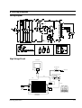
8. Wiring Diagram
Wiring Diagram
High Voltage Circuit
MAGNETRON
HIGH VOLTAGE
DIODE
TO CHASSIS
FA
F
HIGH VOLTAGE CAPACITOR
RED
RED
RED
H.V.FUSE
BRN
RED
BLU
SYMBOL COLOR
BRN
BROWN
BLK
BLACK
RED
RED
BLU
BLUE
ORG
ORANGE
HIGH VOLTAGE
TRANSFORMER
Samsung Electronics
8-1