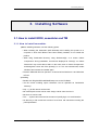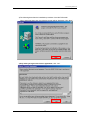
1
REJ10J0822-0100Z M37544 StarterKit User’s Manual RENESAS SINGLE-CHIP MICROCOMPUTER 740 Family 740 Series Rev.1.00 Revision Date : Nov 26, 2004 Renesas Soluctions Corp. www.renesas.com Keep safety first in your circuit designs! 1. Renesas Technology Corporation puts the maximum effort into making semiconductor products better and more reliable, but there is always the possibility that trouble may occur with them. Trouble with semiconductors may lead to personal injury, fire or property damage. Remember to give due consideration to safety when making your circuit designs, with appropriate measures such as (i) placement of substitutive, auxiliary circuits, (ii) use of nonflammable material or (iii) prevention against any malfunction or mishap. Notes regarding these materials 1. These materials are intended as a reference to assist our customers in the selection of the Renesas Technology Corporation product best suited to the customer's application; they do not convey any license under any intellectual property rights, or any other rights, belonging to Renesas Technology Corporation or a third party. 2. Renesas Technology Corporation assumes no responsibility for any damage, or infringement of any third-party's rights, originating in the use of any product data, diagrams, charts, programs, algorithms, or circuit application examples contained in these materials. 3. All information contained in these materials, including product data, diagrams, charts, programs and algorithms represents information on products at the time of publication of these materials, and are subject to change by Renesas Technology Corporation without notice due to product improvements or other reasons. It is therefore recommended that customers contact Renesas Technology Corporation or an authorized Renesas Technology Corporation product distributor for the latest product information before purchasing a product listed herein. The information described here may contain technical inaccuracies or typographical errors. Renesas Technology Corporation assumes no responsibility for any damage, liability, or other loss rising from these inaccuracies or errors. Please also pay attention to information published by Renesas Technology Corporation by various means, including the Renesas Technology Corporation Semiconductor home page (http://www.renesas.com). 4. When using any or all of the information contained in these materials, including product data, diagrams, charts, programs, and algorithms, please be sure to evaluate all information as a total system before making a final decision on the applicability of the information and products. Renesas Technology Corporation assumes no responsibility for any damage, liability or other loss resulting from the information contained herein. 5. Renesas Technology Corporation semiconductors are not designed or manufactured for use in a device or system that is used under circumstances in which human life is potentially at stake. Please contact Renesas Technology Corporation or an authorized Renesas Technology Corporation product distributor when considering the use of a product contained herein for any specific purposes, such as apparatus or systems for transportation, vehicular, medical, aerospace, nuclear, or undersea repeater use. 6. The prior written approval of Renesas Technology Corporation is necessary to reprint or reproduce in whole or in part these materials. 7. If these products or technologies are subject to the Japanese export control restrictions, they must be exported under a license from the Japanese government and cannot be imported into a country other than the approved destination. Any diversion or reexport contrary to the export control laws and regulations of Japan and/or the country of destination is prohibited. 8. Please contact Renesas Technology Corporation for further details on these materials or the products contained therein. Microsoft, MS, and MS-DOS are registered trademarks of Microsoft Corporation of the U.S. Windows is a trademark of Microsoft Corporation of the U.S. IBM and PC/AT are registered trademarks of International Business Machines Corporation of the U.S. Pentium is a trademark of Intel Corporation of the U.S. Adobe and Acrobat are registered trademarks of Adobe Systems Incorporated. Preface Thank you for purchasing Renesas’s M37544 StarterKit. This manual describes how to use the hardware and software products included with M37544 StarterKit. and usage notes as an example of M37544 StarterKit. Refer to a manual supplied with each software for how to control the software Table of Contents Table of Contents 1. Product Concept 4 1.1. Product contents.................................................................................................................4 1.2. Operating environment.......................................................................................................5 1.3. CPU board ..........................................................................................................................5 1.4. CD-ROM .............................................................................................................................6 1.5. System requirements..........................................................................................................7 2. Product Specification 8 2.1. Assembler ...........................................................................................................................8 2.2. TM (Integrated development environment) .......................................................................8 2.3. KD38....................................................................................................................................8 3. Installing Software 3.1. 9 How to install KD38, assembler and TM ...........................................................................9 3.1.1. How to install assembler..............................................................................................9 3.1.2. How to uninstall assembler .......................................................................................15 3.1.3. How to install TM .......................................................................................................16 3.1.4. How to uninstall TM ...................................................................................................22 3.1.5. How to install KD38 ...................................................................................................23 3.1.6. How to uninstall KD38 ...............................................................................................24 3.2. Recognizing FoUSB and installing USB driver ...............................................................25 4. Using 4.1. 4.2. 4.3. 32 Using .................................................................................................................................32 4.1.1. Before starting TM .....................................................................................................32 4.1.2. Assembling with TM ..................................................................................................33 How to use KD38..............................................................................................................38 4.2.1. Before starting KD38 .................................................................................................38 4.2.2. Starting KD38.............................................................................................................39 4.2.3. When communication error occurs...........................................................................41 Operating Sample Program .............................................................................................41 4.3.1. Downloading sample program ..................................................................................41 4.3.2. Executing program.....................................................................................................43 4.3.3. Stopping program ......................................................................................................44 i Table of Contents 4.3.4. Exiting KD38 ..............................................................................................................44 4.3.5. Other ways of use......................................................................................................45 5. Limitations 5.1. 5.2. 46 Assembler limitations........................................................................................................46 5.1.1. Limitations between linker (LINK74M) and assembler (SRA74M)..........................46 5.1.2. Integrated development environment .......................................................................46 5.1.3. Precautions for use of assembler..............................................................................46 Limitations on KD38..........................................................................................................48 5.2.1. Monitor program.........................................................................................................48 5.2.2. Limitations on stop mode and wait mode .................................................................48 5.2.3. Limitations on watchdog timer...................................................................................49 5.2.4. Oscillation stop detection function.............................................................................49 5.3. Limitation on interrupts......................................................................................................49 5.4. Limitations on user's program ..........................................................................................50 5.5. 5.4.1. Allocate user's program.............................................................................................50 5.4.2. Memory map..............................................................................................................50 5.4.3. Limitations when creating user's program ................................................................51 Limitations on Register Control ........................................................................................51 6. Frequently Asked Questions 52 6.1. A communication error occurs at startup.........................................................................52 6.2. A communication error occurs during debugging. ..........................................................52 6.3. Is peripheral I/O operating during a break? .....................................................................52 7. Appendix 7.1. 7.2. 53 CPU board ........................................................................................................................53 7.1.1. Component of CPU board.........................................................................................53 7.1.2. CPU board Specification ...........................................................................................54 7.1.3. Environment Specification.........................................................................................54 7.1.4. Connector Specification.............................................................................................55 7.1.5. Parts Assignments.....................................................................................................56 7.1.6. Block Diagram............................................................................................................57 7.1.7. Memory Map..............................................................................................................58 7.1.8. MCU for StarterKit......................................................................................................59 7.1.9. I/O Port Setting...........................................................................................................60 The Updated Information of M37544 StarterKit ..............................................................61 ii Table of Contents 7.3. Refer to Electoric Manual .................................................................................................61 iii 1. Product Concept 1. Product Concept This chapter describes the product contents of the M37544 StarterKit. When unpacking the M37544 StarterKit, check to see that all products listed below are included. 1.1. Product contents Table 1-1 lists the products included in the M37544 StarterKit. Table 1-1 M37544 StarterKit Product Information Product List Quantity (CPU board 1 pc FoUSB (Use for connecting CPU board and host computer) 1 set CD-ROM 1 pc Packing List 1 pc Release Note 1 pc CD-ROM Packing List Release Note 4 1. Product Concept 1.2. Operating environment Each software supplied with the M37544 StarterKit operates on the host computer and under the OS version that are listed respectively in Table 1-2. Table 1-2 Operating Environment Host Computer IBM PC/AT series or its compatible machine with USB1.1 OS Microsoft Windows 98SE / ME / 2000 / XP CPU PentiumIII 600MHz or newer Memory 128 Mbytes or above 1.3. CPU board The CPU board incorporates the MCU (M37594G2) for Renesas Technolgy Corp 8-bit single-chip MCU StaterKit. 5 1. Product Concept 1.4. CD-ROM The CD-ROM contains necessary software products for developing program and electronic manuals as well. The contents of the CD-ROM are shown as below. \ |-English |-DOCUMENT Manual on MCU |-M3A7535 Manual on M37544 StarterKit | |-CIRCUIT Circuit Diagram of CPU board | |-PROGRAM | |-SAMPLE Sample program file for operation check | |-GNU | |-DOC | |-W95 File on GNU | |-BIN | | |- MAK377 Necessary file for TM | | |- MAK375 Necessary file for TM | |-MAK377 Necessary file for TM | |-MAK375 Necessary file for TM | | | |- SRC |-SRA74M | |- MANUAL Manual on assembler | |- RNOTE Manual on assembler | |- W95E Installer file of assembler | |- MANUAL Manual on TM | |- RNOTE Manual on TM | |- W95E Installer file of TM | |-TM | |-KD38 | |-W95E Installer file of KD38 | |-USB Drivers USB driver | |- MANUAL Manual on KD38 6 1. Product Concept | |- RNOTE Manual on KD38 | |-APPLICATION NOTE File on application note 1.5. System requirements In addition to the products listed below, prepare the following equipments before you use. 1) Host computer 2) Power supply (when using external power supply) 7 2.Product Specification 2. Product Specification 2.1. Assembler The assembler included with this product is the M3T-SRA74M. The M3T-SRA74M generates debug information files from the assembly language source program. Compared to the M3T-SRA74 regular version of assembler, the M3T-SRA74M is functionally limited to some extent. Refer to 5.Limitations for functional limitations. 2.2. TM (Integrated development environment) The TM is the tool to improve developing efficiency of software by integrating the tool groups such as assembler/KD38/editor into the common graphical user interface (GUI). 2.3. KD38 The KD38 is software to operate on a host computer. The KD38 communicates with a firmware for the M37544 written into the MCU (M37594G2) ROM for Renesas Technolgy Corp 8-bit single-ship MCU StaterKit and the KD38 provides high-functional debug environment. The feature of the emulator software is shown below. 1)The source line debugs of assembly language and structural assembly language are possible. 2)The address match break is available at up to 2 points. 3)RAM modification can be watched during the user's program execution. 4)Refer to a datasheet for available maximum frequency which can be equipped on the CPU board. 8 3.Installing Software 3. Installing Software 3.1. How to install KD38, assembler and TM 3.1.1. How to install assembler 1)Before installing software, note the following points. • When installing the assembler (M3T-SRA74M) and installing this product to a computer in which M3T-SRA74 have been already installed, do not install this product. • When using “Destination Directory” using “Reference(R)”, on a screen “Select Components” during installation, some drives displayed at “Drive(V)” on “Select Directories” may not be able to select. In this case, return to “Select Components” and designate a drive with “Disc Space(S)” in it. If it is not executed well, restart Windows and execute the installer again. • The M3T-SRA74M does not operate in a version before Windows3.1 and Windows NT3.5x. 2)Installing • Double-click \English\SRA74M\W95E\setup.exe on the CD-ROM. • No file names including space characters can be specified as “Destination Directory”. • Only 1 (.) for file names can be used. • No network path names can be used. Assign a drive name and use it. • No short-cut can be used. • The “...” symbol cannot be used as a means of specifiying 2 or more directories. • No directory or file names that consist of more than 128 characters including the path specification. 9 3.Installing Software 3)The following describes the installation procedure of the M3T-SRA74M. When executing Setup.exe, the following screen will be displayed. Click “Next”. 4)Only when you agree with license agreement, click “Yes”. 10 3.Installing Software 5)Enter in items and click “Next”. 6)Enter in items and click “Next”. 11 3.Installing Software 7)Enter in items and click “Next”. 8)Enter in items and click “Next”. 12 3.Installing Software 9)Verify the contents completely and click “Next”. 10)Select a folder to be installed and click “Next”. 13 3.Installing Software 11)Select an option and click “Next”. 12)Click “Yes”. 13)Click “OK”. 14)Installation has been completed. 14 3.Installing Software 3.1.2. How to uninstall assembler To uninstall the software, select “Start” - “Setting” - “Control Panel” and click “Add/Remove Application”. When uninstalling the M3T-SRA74M, select “SRA74M V.x.xx” from the program list and click “Add/Remove Application”. The uninstall window will appear and the M3T-SRA74M will be uninstalled. 15 3.Installing Software 3.1.3. How to install TM 1)Note the following points before installing When installing the TM 3.20A Release1 and installing this product to the computer in which the TM has been already installed, install this product after checking the version. 2)Installing • Double-click \English\TM\W95E\setup.exe on the CD-ROM. • No file names including space characters can be specified as “Destination Directory”. • Only 1 (.) for file names can be used. • No network path names can be used. Assign a drive name and use it. • No short-cut can be used. • The “...” symbol cannot be used as a means of specifiying 2 or more directories. • No directory or file names that consists of more than 128 characters including the path specification. 3)The following describes the installation procedure of the TM. When executing Setup.exe, the following screen will be displayed. Click “Next”. 16 3.Installing Software 6)Only when you agree with license agreement, click “Yes”. 7)Enter in items and click “Next”. 17 3.Installing Software 8)Enter in items and click “Next”. 9)Enter in items and click “Next”. 18 3.Installing Software 10)Enter in items and click “Next”. 11)Verify the contents completely and click “Next”. 19 3.Installing Software 10)Select a folder to be installed and click “Next”. 13)Click “Yes”. 14)Click “OK”. 20 3.Installing Software 15)Click “OK”. 16)Click “Finish”. 17)Installation has been completed. 21 3.Installing Software 3.1.4. How to uninstall TM To uninstall the software, select “Start” - “Setting” - “Control Panel” and click “Add/Remove Application”. When uninstalling the TM, select “TM V.x.xx” from the program list and click “Add/Remove Application”. The uninstall window will appear and the TM will be uninstalled. 22 3.Installing Software 3.1.5. How to install KD38 1)Installing Double-click \English\KD38\W95E\setup.exe on the CD-ROM 2)The following describes the installation procedure. Click “Next”. 3)Only when you agree with license agreement, click “Yes”. 23 3.Installing Software 4)Select a folder to be installed and click “Next”. 5)Click “Yes”. 6)Installation has been completed. 3.1.6. How to uninstall KD38 To uninstall the software, select “Start” - “Setting” - “Control Panel” and click “Add/Remove Application”. When uninstalling the KD38, select “KD38 V.x.xx” from the program list and click “Add/Remove Application”. The uninstall window will appear and the KD38 will be uninstalled. 24 3.Installing Software 3.2. Recognizing FoUSB and installing USB driver Recognize the FoUSB and install the USB driver by connecting the FoUSB to the host computer. 1)Copy the USB Drivers folder in \ENGLISH\KD38 on the CD-ROM to the hard disc in the host computer. This manual describes the situation when the USB Drivers folder on the C drive is copied. 2)Remove the FoUSB cover and ensure the FoUSB is set as follows before connecting the FoUSB. When the FoUSB is not set as follows, modify the setting. Place the cover of the FoUSB after verifying the setting. Power supply switch (S1: Power Mode): USB MCU mode pin (JP1: MCU Mode): Open JP1: Open S1:USB side 3)Connect the FoUSB to the host computer. Since Windows detects new hardware, recognizing the FoUSB and installing the USB driver start. Host Computer USB Cable FoUSB 25 3.Installing Software NOTES: The USB driver (USB Drives folder) copied into the C drive is designated to recognize the FoUSB. This manual describes recognition of the FoUSB and how to install the USB driver in Windows XP and Windows 98SE. Note that designation mean of the USB driver varies depending on the operation system to be used. <Windows XP> 4)When connecting the FoUSB to the host computer, Windows detects new hardware. Select “Install from a list or specific location (Advanced)” and click “Next”. 26 3.Installing Software 5)Select “Search for the best driver in these locations”. Check “Include this location in the serach” and designate the driver in which the USB folder is included. “C:\USB Drivers” is selected here. Once the folder can be designated, click “Next”. 27 3.Installing Software 6)Although a warning screen shown below is displayed from Windows, click “Continue”. NOTES: Microsoft has advocated authentication of the USB drivers to the USB vendors in the Microsoft® Windows® XP and Windows®-based operating systems released after Microsoft® Windows® XP. This is aimed at elimination of illegal drivers and improvement of host computer (PC). Renesas USB Drivers are not authenticated by Microsoft, but we provide them baased on the sufficient examination. 7)Finally, click “Finish”. Recognition of the FoUSB and installing the USB driver in Windows XP have been completed. 28 3.Installing Software <Windows 98SE> 4)When connecting the FoUSB to the host computer, Windows detects new hardware. and click “Next”. 5)Select “Search for the best driver for your device (Recommended)” and click “Next”. 29 3.Installing Software 6)Select “Specify a location” and designate the driver in which the USB folder is included. “C:\USB Drivers” is selected here. Once the folder can be designated, click “Next”. 7)Click “Next”. 30 3.Installing Software 8)Finally, click “Finish”. Recognition of the FoUSB and installing the USB driver in Windows 98SE have been completed. 31 4.Using 4. Using 4.1. Using 4.1.1. Before starting TM Ensure the host computer and CPU board are firmly connected. (Refer to Figure 4-1 Connection Diagram of CPU board.) Turn the power mode switch of RTA-FoUSB-MON to USB side. Host Computer USB Cable FoUSB User Cable CPU board Figure 4-1 Connection Diagram of CPU board 32 4.Using 4.1.2. Assembling with TM 1)This sub-section describes how to use the TM easily with a sample program attached to the CD-ROM as an example. Refer to the TM user’s manual for how to use the TM. It is possible to browse the TM user’s manual in order of “Start” - “Program” “RENESAS-TOOLS” - “TM V.x.xx” - “TM user’s manual”. 2)Copy the sample program (\English\M3A7535\PROGRAM) included CD-ROM to the rewritable drive such as a hard-disc. Next, modify the drive which can be read or written by property of the file since the copied sample program folder and file attribute in a folder is set to “Read-only”. 3)Starting TM When clicking in order of “Start” - “Program” - “RENESAS-TOOLS” - “TM V.x.xx”” “TM” for the TM, the window will appear. (Refer to Figure 4-2 TM Project Bar) (1) (2) (3) Figure 4-2 TM Project Bar 33 4.Using 4)Create a new project When clicking (1) of Figure 4-2, a new project screen of Figure 4-3 will be displayed. Figure 4-3 Screen of New Project Step 1 5)Select “740 Family” for a target chip on Figure 4-3. Enter a project name to anywhere. Designate a directory which copied a sample program for a working directory and click “Next”. Example) Project Name : Sample Working Directory : C:\sample\sample 34 4.Using 6)Select a project kind on Figure 4-4. The sample program is created by the assembler. Select “ASM Project“ and click “Next”. Figure 4-4 Screen of New Project Step 2 7)Designate a compiler package on Figure 4-5. Figure 4-5 Screen of New Project Step-Compiler 35 4.Using 8)A screen of Figure 4-6 is displayed and the project will be finished. Figure 4-6 Screen of New Project Step-Finish 9)Open a project editor. Add a source program and set an assembler option. Click (2) of Figure 4-2, the project editor will be displayed. Figure 4-7 Project Editor 36 4.Using 10)When double-clicking “all” marked with a red circle in Figure 4-7, “Sample hex” will be displayed. Add a source program. Select “Project” - “Edit Item” - “Add File” while selecting “Sample.hex” 11)A source program will be open. (Example : Open “C: \sample\sample.a74”) 12)Perform assembling finally. Click (3) of Figure 4-2 (Build button). 37 4.Using 4.2. How to use KD38 4.2.1. Before starting KD38 1)Ensure the KD38 is installed. 2)Ensure a computer and the CPU board are connected (Refer to Figure 4-8 Connection Diagram of CPU board). 3)Ensure the power is supplied to the CPU board. Host Computer USB Cable FoUSB User Cable CPU board Figure 4-8 Connection Diagram of CPU board 38 4.Using 4.2.2. Starting KD38 1)Click “Start” - “Program” - “RENESAS-TOOLS” - “KD38 V.x.xx" - “KD38" from the start menu to start the KD38. When the KD38 starts, the INIT screen of the KD38 which is shown in Figure 4-9 will be open. When a window is open, click “Refer” and select the target MCU. Click! Figure 4-9 INIT Screen 1 of KD38 2)Next, Figure 4-10 will be open. Select “M37544STK.MCU” on the target MCU. Figure 4-10 MCU File Screen 39 4.Using 3)When selecting the target MCU, the INIT screen of KD38 in Figure 4-11. Click “OK”. Do not check here!! Figure 4-11 INIT Screen 2 of KD38 4)When a normal communication is performed, KD38 on Figure 4-12 will be open. Figure 4-12 Main Screen of KD38 40 4.Using 4.2.3. When communication error occurs When a communication error occurs, an error window of Figure 4-13 will be displayed. Click “OK” and check the following points. Check 1 : Ensure the power is supplied to the CPU board. Check 2 : Ensure the power supply of the FoUSB is not specified as TARGET. Check 3 : Ensure the USB_cable, FoUSB, User_Cable and CPU board are connected. Figure 4-13 Example of Communication Error Window Supply the power again and restart the KD38 after checking all. 4.3. Operating Sample Program 4.3.1. Downloading sample program 1)Select “File” - “Download” from the KD38 screen and download the sample program compiled at “4.1 Using” . (Figure 4-14) Figure 4-14 Download Screen 41 4.Using 2)When the download completes, the program downloaded to ”Program window” will be displayed. (Refer to Figure 4-15 Program Window Screen) Figure 4-15 Program Window Screen 42 4.Using 4.3.2. Executing program When the download completes, the KD38 screen will be displayed as Figure 4-16. Press the “GO” button on the KD38 screen to execute the sample program. GO Button Figure 4-16 Before Executing a Program 43 4.Using 4.3.3. Stopping program Next, press the “STOP” button on the KD38 screen to stop the executed sample program. And the sample program will stop. STOP Button Figure 4-17 During Executing a Program 4.3.4. Exiting KD38 1)Stop the sample program before exiting the KD38 2)Select “File” - “Exit” of the KD38. Since Figure 4-18 is open when selecting the “Exit” menu, click “OK”. When clicking “Cancel”, the KD38 will not be exited. Figure 4-18 Exit Window 44 4.Using 4.3.5. Other ways of use The KD38 contains abundant functions. Browse “Start” - “Program” - “RENESAS-TOOLS” - “KD38 V.x.xx” - “KD38 Help” from the start menu for details of how to use the KD38. 45 5.Limitations 5. Limitations 5.1. Assembler limitations 5.1.1. Limitations between linker ( LINK74M ) and assembler ( SRA74M ) The attached user’s manual is described about an assembler (SRA74). The following SRA74M spec is different from SRA74. 1)The structured language cannot be used. 2)Macro commands cannot be used. 3)An object file can link to three. 4)An assembler command option can use only -C, -L, -LS and -S. 5)The assembler (SRA74M) and linker (LINK74M) are provided. 5.1.2. Integrated development environment Inspector function of the TM and creating a library project cannot be used. 5.1.3. Precautions for use of assembler 1)When the number of lines of one source file crosses 65535 lines, relocatable file is not sometimes generated right in the SRA74M. When the relocatable file is not generated right, internal error occurs in the LINK74M. [Condition] An internal error will occur when the following 2 conditions are met: (1) The number of lines of 1 source file crosses 65535 lines. (2) The SRA74M is started by adding the -C option. [Countermeasure] Avoid in either following way. (1) Divide a file so as not for 1 source file to cross 65535 lines. (2) Start the SRA74M without adding the -C option. 46 5.Limitations 2)When a line with 255 or more characters exists in 1 source file, the assembly of the line is not sometimes performed right. In this case, an error occurs in the SRA74M or LINK74M. Except for the line only of the comment, make the maximum number of characters with 1 line 255 digits or below. 3)Describing a symbol for forward-referencing in the conditional expression in conditional assembling results in the assembling being terminated unsuccessfully processed correctly and the SRA74M will be completed incorrectly. [Example] .section P .IF BBB ;A symbol for foward-referencing described in the conditional expression lda AAA .ELSE nop .ENDIF BBB .equ 0 ;The symbol defined .end [Countermeasure] Do not describe any symbol for forward-referencing in the conditional expression in conditional assembling. 4)Foward-referencing a label in a relocatable zero-page section causes incorrect data to be written to the HEX file. [Example] .section P .org 1000h lda YY nop .section Z YY: .blkb 2 ;A label defined .end [Countermeasure] Do not forward-reference any label in a relocatable zero-page section. 47 5.Limitations 5.2. Limitations on KD38 5.2.1. Monitor program The MCU on the CPU board incorporates a monitor program. There are some following precautions when operating the KD38 with this monitor program. Refer to “5.4 Limitations on user's program”. 1) Do not perform the step operation and break to the process of the user stack setting. Set the the stack setting process to interrupt disable status. (I flag =1) 2) Reset a stack pointer to $00FF for a monitor program. 3) The monitor program uses $2000 to $207F and the reserved area of 7544 MCU SFR. Do not modify the data in this area. 4) The monitor program uses an interrupt. Do not set to interrupt disable state (I flag = 1) in a program other than the stack setting process. 5) When the step operation of the debugger is performed to the I flag control instruction, the user interrupt process may be operated. A break point set in the user interrupt process will be disabled. Do not execute the step operation to the I flag control instruction. (I flag control instruction : CLI,SEI,PLP,PHP,RTI) 6) When an interrupt is acknowledged, the branch to the interrupt process of the user's program will be performed via the monitor program. Therefore, real time of the user's program will not be guaranteed. 7) When pressing a reset switch of the CPU board, reload the user's program. 8) Do not perform the step operation for the branch instruction to the self-address. Example) NOP LOOP: BCC LOOP Do not perform the step operation for this NOP instruction 5.2.2. Limitations on stop mode and wait mode When using stop mode and wait mode in the user's program, close the RAM monitor window and watch window in advance before executing. Do not generate a memory access by the debugger during executing the user's program. 48 5.Limitations 5.2.3. Limitations on watchdog timer A monitor program does not reset a watchdog timer. When using a watchdog timer, close the RAM monitor window and watch window in advance before executing. Do not generate a memory access by the debugger during executing the user's program. 5.2.4. Oscillation stop detection function When starting a reset by the oscillation stop detection, the monitor program operates and may rewrite the user memory. Do not use the oscillation stop detection function. 5.3. Limitation on interrupts User interrupt vector address The branch to the interrupt process of the user's program is performed via the monitor program. Allocate the interrupt vector of the user's program to the following addresses. Also, the monitor program uses the BRK instruction interrupt. This interrupt cannot be used on the user's program. Table 5-1 User Interrupt Vector Address Interrupt Factor user's program Location Address Enabled/Disabled Reset 3FFC16 to 3FFD16 Enabled Serial I/O Receive 3FFA16 to 3FFB16 Enabled Serial I/O Transmit 3FF816 to 3FF916 Enabled INT0 3FF616 to 3FF716 Enabled INT1 3FF416 to 3FF516 Enabled Key-On Wake-Up 3FF216 to 3FF316 Enabled CNTR0 3FF016 to 3FF116 Enabled CNTR1 3FEE16 to 3FEF16 Enabled Timer X 3FEC16 to 3FED16 Enabled Timer A 3FE616 to 3FE716 Enabled A/D Conversion 3FE216 to 3FE316 Enabled Timer 1 3FE016 to 3FE116 Enabled BRK Instruction 3FDC16 to 3FDD16 Disabled 49 5.Limitations 5.4. Limitations on user's program 5.4.1. Allocate user's program A MCU address map for the StarterKit is shown in Table 5-2. Allocate the user's program to the RAM2 area. Special page addressing mode cannot be used. Allocate the interrupt vector to the address in Table 5-1. Table 5-2 MCU Address Map for StaterKit Name Address Memory Enabled/Disabled Limitation SFR Area (Zero Page) 000016 to 003F16 RAM Enabled NOTE) Refer to Table 5-3. RAM1 (Zero Page) 004016 to 00FF16 RAM Enabled - RAM1 010016 to 013F16 RAM Enabled - RAM2 (Monitor Program Area) 200016 to 207F16 RAM Disabled Disabled RAM2 208016 to 3FDB16 RAM Enabled - RAM2 (User Interrupt Vector Area) 3FDC16 to 3FFD16 Enabled BRK instruction interrupt disabled ROM (Monitor Program Area) E00016 to FFFD16 Disabled Disabled RAM ROM 5.4.2. Memory map Figure 5-1 shows a memory map of Renesas 8-bit single-chip MCU M37594G2 which the CPU board incorporates. The user enabled area is (SFR RAM1 256 B, RAM2 8KB). Figure 5-1 Memory Map 50 5.Limitations 5.4.3. Limitations when creating user's program 1)When setting a stack pointer in the user's program, set to interrupt disable status (I flag=1). 2)A monitor program uses the 5-byte user stack. Leave 5-byte memory of the user stack for the monitor program. 3)Do not perform read or write to the reserved area of SFR in the 7544 group. 4)Do not modify the bit 6 in the interrupt control register 2. Also, set the bit 6 to “1” when modifying this register. 5.5. Limitations on Register Control Table 5-3 lists the limitations on the register control. The monitor program cannot operate correctly when modifying the register which is disabled to modify. Table 5-3 Limitations on Register Control Register Interrupt Control Register 2 $003F Default Value Reset to 4016 Limitation Do not modify bit 6 Modification √ (Set bit 6 to “1”) Interrupt Request Register 2 $003D - Set bit 6 to “1” Modification is enabled or disabled by the user's program √ : Modification is enabled (Limitation in part) 51 √ 6.Frequently Asked Questions 6. Frequently Asked Questions 6.1. A communication error occurs at startup. When a communication error occurs at startup, check the following contents. 1)Ensure the USB_cable and user cable connected. 2)Ensure the power is supplied to the CPU board when using the external power. 6.2. A communication error occurs during debugging. When a communication error occurs during debugging, check the following contents. 1)The firmware may be out of control by the user's program (out of control or accessing to monitor area). Remove the USB_cable of FoUSB and connect it again. Restart the KD38. 2)Communication with FoUSB cannot be performed while the interrupt is disabled. Do not disable the interrupt. 3)When writing large data with memory writing control (e.g.Fill) at one time, communication with FoUSB may not be performed. Perform memory writings in several times. 6.3. Is peripheral I/O operating during a break? Although interrupts cannot be acknowledged during a break, peripheral I/O continues operating. If the user's program is halted by a break after starting a timer, the timer continues counting, but the timer interrupts cannot be acknowledged. 52 7.Appendix 7. Appendix 7.1. CPU board 7.1.1. Component of CPU board Figure 7-1 shows the component of the CPU board. MCU [M37594G2FP] Through hole CN1 CN2 [Debug Port] Buzzer SW1 [Reset] SW3 [INT0] SW2 [INT1] LED Figure 7-1 CPU board Component 53 7.Appendix 7.1.2.CPU board Specification Table 7-1 lists the specification of the CPU board. Table 7-1 CPU board Specification Item MCU Memory Connector Switch LED Buzzer Content M37594G2FP Operation mode : Single-chip mode Clock frequency : Main clock 8MHz Internal Memory RAM : 256 bytes+8 Kbytes Flash ROM : 8 Kbytes [CN1] : Through hole for power connector [CN2] : Communication connector (for FoUSB) [SW1] : Connect to RESET [SW2] : Connect to INT1 [SW3] : Connect to INT0 [LED2] : Connect to P3_0 (red) [LED3] : Connect to P3_1 (yellow) [LED4] : Connect to P3_2 (green) Buzzer 7.1.3. Environment Specification Table 7-2 shows the environment condition in use and when storing.. When storing the products, put them in the conductive bag and place and store them into the package to ship. Table 7-2 Environment Specification Environment Condition Ambient Temperature Ambient Humidity Supply Voltage Use Environment Operation Ambient Temperature : 25±5[C] 30 to 80[%] (No dewdrops allowed) 4.5 to 5.5[V] 30 to 80[%] (No dewdrops allowed) (No corrosive gas allowed) Store Environment Store Ambient Temperature : 25±5[C] (No corrosive gas allowed) 54 7.Appendix 7.1.4. Connector Specification Figure 7-2 shows the pin assignment of CN2. Pin No.1 Connector Type HIF3FC-10PA-2.54DSA Pin No Port Signal KD connector 1 3 5 7 9 1 2 4 6 8 10 2 P4_3 BUSY 3 P4_2 SCLK Output Input 4 P4_0 RxD Input 10-Pin Connector Vcc 5 Not Used 6 Not Used 7 GND 8 RESET 9 10 Not Used P4_1 TxD Output 10-Pin Connector assign Figure 7-2 Pin Assignment of CN2 55 7.Appendix 7.1.5. Parts Assignments The CPU board contains 3 LEDs, 3 switches and 1 buzzer. Also, it contains the through hole for external output. Figure 7-3 shows the parts assignment. MCU [M37594G2FP] Through hole CN1 CN2 [Debug Port] Buzzer SW1 [Reset] SW3 [INT0] SW2 [INT1] LED Figure 7-3 Parts Assignments of CPU board 56 7.Appendix 7.1.6. Block Diagram Figure 7-4 shows the block diagram of the CPU board. Figure 7-4 Block Diagram of CPU board 57 7.Appendix 7.1.7.Memory Map Figure 7-5 shows a memory map of the Renesas 8-bit single-chip MCU M37594G2 which the CPU board incorporates. The user enabled area is (SFR RAM1 256 B, RAM2 8KB). Figure 7-5 Memory Map of M37594G2 58 7.Appendix 7.1.8. MCU for StarterKit The CPU board incorporates the MCU M37594G2 of Renesas 8-bit single-chip MCU 7544 Group emulator. The electrical characteristics of the M37594G2 is equivalent to the ones of the M37544G2 Figure 7-6 shows the pin assignment of the M37594G2. Sine a monitor uses No. 25 to 28 pin, the user cannot use them. Figure 7-6 Pin Assignment of M37594G2 59 7.Appendix 7.1.9. I/O Port Setting (1)LED The LED2 to 4 are connected to the programmable I/O port. They can be lighted by a program. Table 7-3 LED Pin LED PORT Pin No LED2 P30 19 LED3 P31 20 LED4 P32 21 (2)Switch The [SW2] and [SW3] are switches connected to the P34/INT1 and P37/INT0 pins in the MCU. The [SW1] is a switch connected to the RESET input pin in the MCU. The user can use each switch for any function. The connection with each switch and the input pin are as follows. SW Input Pin SW1 RESET SW2 P34/INT1 SW3 P37/INT0 60 Remarks 7.Appendix 7.2. The Updated Information of M37544 StarterKit Regarding supports for this product, no supports are provided at all. If there is any concern or suggestion about this product or anything that you noticed in use, please send your opinions to the mail address shown below. Your opinions will be reflected in the examination of future improvements. Please note that all mails may not be able to be replied. [email protected] 7.3. Refer to Electoric Manual The Acrobatt Reader is required to refer the electric manuals of this product. The user can download the Adobe Acrobat Reader from the home page of Adobe Systems Incorporated. Refer to the following URL for the updated information of the Adobe Acrobat Reader. http://www.adobe.co.jp/ http://www.adobe.com 61 REVISION HISTORY Rev. Description Date Page 1.00 2004.11.26 - Summary First edition issued M37544 StarterKit User’s Manual Publication Date Rev.1.00 November 26, 2004 Published by: Renesas Soluctions Corp. 4-1-6, Miyahara, Yodogawa-ku, Osaka City, 532-0003, Japan ©2004 Renesas Technology Corp. and Renesas Solutions Corp., All Rights Reserved. Printed in Japan. M37544 StarterKit User’s Manual Renesas Soluctions Corp. 4-1-6, Miyahara, Yodogawa-ku, Osaka City, 532-0003, Japan