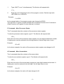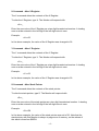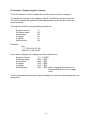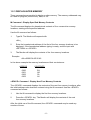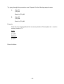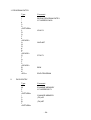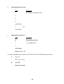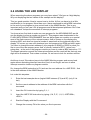
1
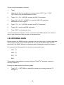
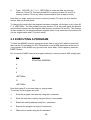
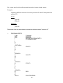
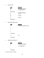
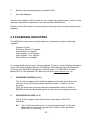
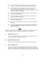
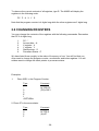
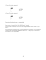
MVS-AIM65
Users
Manual
MONITOR FOR THE
Mitsubishi / Renesas
M38039 / M38049
Microprocessors
and the
MSV38049-SKP
Preface
This is the User Manual for the AIM65 converted to be used with the Mitsubishi /
Renesas M38039 / M38049 Microprocessors and the Mitsubishi MSV38049-SKP
Starterkit.
The MSV-AIM is a powerful tool for testing and developing microprocessor hard- and
software.
It is specially made to test hardware in the development phase of a project, because
you can:
- download and upload programs
- check and alter memory
- check and alter internal microprocessor registers
- start and alter programs
- use the LED display of the starter kit
The MSV-AIM monitoring program is ready to use when flashed into the MSV38049SKP starter kit.
You only have to connect this MSV38049-SKP via RS232 to your PC, start your
Hypertext, and connect the MSV38049-SKP to power. The Module will give a response
and you can start.
A description of the usage of this monitor you will find within this paper.
The Monitor uses flash memory from E000-FFFF, the CoEd uses flash memory from
9000-9FFF and RAM area up to 01FF (Monitor) and 0200-021F (CoEd). All other flash
areas (1000-8FFF and A000-BFFF) are free for your programs. With this monitor you
can download and test your programs into RAM area 0300-07FF and then you have
some space for variables at addresses 0220-02FF.
Free zero page addresses are from address 00F5 to address 00FF.
If you like to get this Monitor onto an M38039 or M38049 Microprocessor, then you
have to download the file MSVAIMCOED.hex to the programmer, erase the flash of the
Microprocessor and then program the flash. If you have done this (checksum 9000FFFF is 1722), the Monitor is ready to use.
To switch on the LED display of the MSV38049-SKP, simply press D on your keyboard
- to see your measuring value on this display, write the 16-bit hex value into memory
00F3/00F4 - the display will show it.
I hope you will have a good testing time and good results of your work!
May 2007
Dirk Bruehl
Contents:
1.
THE AIM65 MONITOR
1
1.1
AIM65 MONITOR FEATURES
1
1.2
MAJOR FUNCTIONS
2
1.2.1
RESET - ENTER AND INTIALIZE MONITOR
2
1.2.2
DISPLAY/ALTER REGISTERS
2
1.2.3
DISPLAY/ALTER MEMORY
6
1.2.4
INSTRUCTION ENTRY/DISASSEMBLY
8
1.2.5
EXECUTION COMMAND G
12
1.2.6
LOAD/UPLOAD MEMORY
13
2.
PROGRAMMING
16
2.1
ENTERING A PROGRAM
16
2.2
ENTERING DATA
19
2.3
EXECUTING A PROGRAM
20
2.4
USING THE LED DISPLAY
26
2.5
EXAMINING REGISTERS
27
2.6
CHANGING REGISTERS
29
3.
MVSAIMCoED
31
4.
The MVS AIM65 CoED story
34
1. THE AIM65 MONITOR
The AIM65 Monitor is a computer program, that provides powerful software features
and linkages to both AIM65 and user programs. The Monitor is located in the flash
memory area E000-FFFF, the AIM65 CO-ED (see MSVAIMCoEd) is located in the flash
memory area 9000-9FFF.
1.1 AIM65 MONITOR FEATURES
The features of the AIM Monitor include:
Major function entry and re-entry linkage -- easy linkage to and from Monitor and
user functions. Single keystroke or RESET button depression returns control to the
Monitor.
Display and alter any register -- any of the six microprocessor registers and any
of the 76 I/O registers may be displayed and altered.
Display and alter memory -- any ram memory location may be displayed and
altered.
Instruction mnemonic entry -- R6500 machine language instructions may be
directly entered into memory from typed mnemonic operation codes and
hexadecimal operands.
Disassemble memory -- R6500 object code may be decoded (disassembled)
from memory into R6500/MELPS740 mnemonics and hexadecimal operands.
Execution control -- user programs can be initiated at specified program counter
values.
BRK instruction control -- BRK instructions may be place in a user program to
stop execution at this point.
Load and Upload memory to and from your pc.
User defined interface keys -- three keys are dedicated to link directly to userdefined functions with simple return capability to the Monitor.
The <ESC> command provides re-entry into the Monitor from most AIM65
functions. The RESET button always returns control to the Monitor and performs
"cold" or "warm" initialization.
-1-
1.2 MAJOR FUNCTIONS
1.2.1 RESET - ENTER AND INTIALIZE MONITOR
The RESET command performs a hardware reset of the I/O and initializes the AIM65
Monitor.
Perform a "warm" reset by depressing the RESET button on the microprocessor board.
Perform a "cold" reset by either turning the microprocessor boards power off, waiting a
couple of seconds, and then reapplying power to the microprocessor board or by
changing address 014A to 00 and then depressing the RESET button.
Example:
Press RESET
ROCKWELL AIM 65
<ESC> Command - Re-enter Monitor
The <ESC> command escapes from the existing command and returns to the Monitor.
<ESC> is operative only in the commands that sample the serial line RS232. The
Monitor will respond to <ESC> by displaying the AIM65 Monitor prompt:
<_
1.2.2 DISPLAY/ALTER REGISTERS
Seven commands are provided to display or alter the contents of the six
microprocessor registers (program counter, processor status, accumulator, X register, Y
register, and stack pointer). The alter commands are used most often to establish initial
register values for checkout purposes. During normal program operation, the register
contents would be initialized by previously executed instructions.
* Command - Alter Program Counter
The * command changes the value of the program counter.
Use the * command as follows:
-2-
1.
Type <SHIFT> and * simultaneously. The Monitor will respond with:
<*>=_
2.
Enter the new hexadecimal value of the program counter. End the input with
<RETURN> or a <SPACE>.
Example:
<*>=0300
In the example above, the program counter was changed to $0300.
The instruction in memory location $0300 will be executed first when the G command
(Start Execution at Program Counter Address) is entered.
P Command - Alter Processor Status
The P command alters the contents of the processor status register.
To alter the processor status register, type P. The Monitor will respond with:
<P>=_
Enter the new value of the processor status register as a two digit hexadecimal number.
A leading zero must be entered in the left digit position if the left digit value is zero.
Example:
<P>=00
In the above example, the value of the processor status register was changed to 00.
A Command - Alter Accumulator
The A command alters the contents of the accumulator.
To alter the accumulator register, type A. The Monitor will respond with:
<A>=_
Enter the new value of the accumulator register as a two digit hexadecimal number. A
leading zero must be entered in the left digit if the left digit value is zero.
Example:
<A>=01
In the above example, the value of A was changed to 01.
-3-
X Command - Alter X Register
The X command alters the contents of the X Register.
To alter the X Register, type X. The Monitor will respond with:
<X>=_
Enter the new value of the X Register as a two digit hexadecimal number. A leading
zero must be entered in the left digit if the left digit value is zero.
Example:
<X>=02
In the above example, the value of the X Register was changed to 02.
Y Command - Alter Y Register
The Y command alters the contents of the Y Register.
To alter the Y Register, type Y. The Monitor will respond with:
<Y>=_
Enter the new value of the Y Register as a two digit hexadecimal number. A leading
zero must be entered in the left digit if the left digit value is zero.
Example:
<Y>=03
In the above example, the value of the Y Register was changed to 03.
S Command - Alter Stack Pointer
The S command alters the contents of the stack pointer.
To alter the stack pointer, type S. The Monitor will respond with:
<S>=_
Enter the new value of the stack pointer as a two digit hexadecimal number. A leading
zero must be entered in the left digit if the left digit value is zero.
Example:
<S>=D9
In the above example, the value of the stack pointer was set to D9. Note that the
stack pointer with this Monitor is always in page zero of memory, so the adress of
the stack is therefore $00D9.
-4-
R Command - Display Register Contents
The R Command is used to display the current contents of the six registers.
To display the contents of the registers, type R. The Monitor will show two lines.
The first line shows the symbols for the registers and the second line shows the
actual contents.
The registers and their corresponding symbols are:
Program counter
Processor status
Accumulator
X register
Y register
Stack pointer
****
PS
AA
XX
YY
SS
Example:
<R>
***** PS AA XX YY SS
0300 00 01 02 03 D9
In the above example, the registers and their contents are:
Program counter
Processor status
Accumulator
X register
Y register
Stack pointer
(****) = $0300
(PS) = $00
(AA) = $01
(XX) = $02
(YY) = $03
(SP) = $D9 (which means that the stack is at
address $00D9 since it is on page
zero.)
The R commands also provides column headings for reference when breakpoints are
being used.
-5-
1.2.3 DISPLAY/ALTER MEMORY
Three commands are provided to display or alter memory. The memory addressed may
be used for program (instructions), data, or I/O.
M Command - Display Specified Memory Contents
The M command displays the hexadecimal contents of four consecutive memory
locations, starting at the specified address.
Use the M command as follows:
1.
Type M. The Monitor will respond with:
<M>=_
2.
Enter the hexadecimal address of the first of the four memory locations to be
displayed. If the hexadecimal address typing is ready, end the input with
<RETURN> or <SPACE>.
3.
The Monitor will display the contents of the four memory locations.
Example:
<M>=0300 EA AD 00 A2
In the above example the memory locations and their contents are:
ADRESS
0300
0301
0302
0303
CONTENTS
EA
AD
00
A2
<SPACE> Command - Display Next Four Memory Contents
The <SPACE> command displays the contents of the next four memory locations, after
the initial address value has been entered using the M command. Use the <SPACE>
command as follows:
1.
Use the M command to display the first four memory locations.
2.
Press the <SPACE> key. The Monitor will display the contents of the next
four memory locations.
After the initial use of the M command, the <SPACE> command may be used any
number of times.
-6-
NOTE
If the M command is not used first to initialize the starting
memory location, a random starting memory location will appear.
/ Command - Alter Memory Contents
The / command alters any changeable memory location displayed with the M command
or the <SPACE> command.
Use the / command as follows:
1.
Display the memory location to be altered using M command or <SPACE>
command.
2.
Type /.
3.
The Monitor will respond with the address of the first memory location that
was displayed on the previous line.
4.
If the first memory location is to be altered, enter the new contents as a hex
number. If the location is to be left as is, type one <SPACE>.
5.
Proceed to the next location and alter it, if needed.
6.
When the changing of the locations displayed is complete, press <RETURN>.
If the last memory location on the line was altered, no <RETURN> is necessary.
7.
To alter the next four locations, re-enter the command /.
Example:
<*>=0300 EA AD 00 A2
</> 0300 0F 27
In the above example, the following operations were performed:
Location 0300 was changed to $0F.
Location 0301 was left unchanged (one <SPACE> was entered).
Location 0302 was changed to $27.
Location 0303 was unchanged (<RETURN> was entered after
Location 0302 was changed).
If an attempt is made to alter protected, write-only address, flash, or failed memory,
the Monitor will display a MEM FAIL message along with the address that caused the
error.
-7-
Example:
<M>=1000 FF FF FF FF
</> 1000 30
MEM FAIL 1000
If there is a address you can write, but not read back, the same result will appear.
Example:
<M>=0030 0D 80 B0 E0
</> 0030 44D
MEM FAIL 0030
This is a special example. Memory location $0030 is the serial transmit register for
the serial port 3, which is used for the connection to your terminal via RS232. The
typed value 44 will be sent by the serial interface and you get the result (44 is the
ASCII value of the character D) on the screen directly after the value you typed to
change the memory (the first seen value 0D is the ASCII sign for <RETURN>, this was
the last character you typed after the M command.
1.2.4 INSTRUCTION ENTRY/DISASSEMBLY
Two commands allow easy entry of R6500 instructions into memory and examination of
instructions already in memory.
The I command encodes (or assembles) symbolic instructions entered on the keyboard
into directly executable object code stored in memory. The K command decodes (or
disassembles) object code from memory into symbolic instructions for user
examination.
I Command - Instruction Mnemonic Entry
The I command enters R6500 instructions directly into memory as object code from
symbolic instructions entered from the keyboard. Starting from user entered address,
operation codes (op codes) are entered using three-digit alphabetic abbreviations.
Operands, if required, are entered in hexadecimal in accordance with the addressing
mode formats. Invalid opcodes and operands are ignored but cause an ERROR
message to be displayed.
Use the I command as follows:
1.
Type I. The Monitor will respond with the current program counter address:
<I>
0300
-8-
2.
The program counter address can be changed by typing * followed by a fourdigit hexadecimal address. If address 0400 is entered, the Terminal will respond with:
0300
0400
3.
*=0400
Enter the three-digit alphabetic abbreviation of the operation code. An input
error in either of the first two digits may be corrected by using the backspace
key and typing the correct character. The backspace key will be responded with:
/
If the entered opcode does not require an operand, the object code is
computed, stored in memory, and displayed in object code form along with
the program counter address and the symbolic opcode. The program counter
is incremented by one.
If you want to enter additional instructions to successive addresses, return
to step 3. If instruction entry is complete, return to the Monitor by pressing
<ESC>.
If the op code requires an operand, continue to step 4.
If the opcode is invalid, an ERROR message will appear. The correct op code
may then be re-entered without altering the program counter address since it has
not been incremented.
If a valid but undesired opcode was entered, it may be corrected in one of
two ways:
A. If the opcode requires an operand, enter <RETURN> before entering an
operand or deliberately enter an invalid operand. An ERROR message will
be generated and the whole instruction can be re-entered since the
program counter address was not changed.
B. If the opcode does not require an operand, the object code was entered
into memory and the program counter incremented. In this case, reestablish the previous program counter address as in step 2.
4.
Enter the operand in hexadecimal in accordance with the addressing mode
formats. In some cases, a short form is allowed. The Monitor shows the
standard format except for branch instructions, which show the absolute address
rather than the relative address. This is that you not have to calculate the relative
addresses.
-9-
The form for operand entry in the appropriate address mode is shown below (where H
is the hexadecimal data):
ADRESSING MODE
Accumulator
Immediate
Zero Page
Zero Page, X
Zero Page, Y
Absolute
Absolute, X
Absolute, Y
Relative
(Indirect, X)
(Indirect), Y
(Indirect)
OPERAND FORMAT
A
#HH
HH
HH,X or HHX
HH,Y or HHY
HHHH
HHHH,X or HHHHX
HHHH,Y or HHHHY
HH or HHHH
(HH,X) or (HHX)
or (HH,X or (HHX
(HH),Y or (HH)Y
(HHHH)
NOTES
(1)
(1)
(1)
(1)
(2)
(2)
(2)
(4)
(1)
(1)
(1)
(2)
NOTES
(1)
Immediate, page zero, or relative addresses require the entry of two digits
(HH).
(2)
Absolute addresses require the entry of four digits (HHHH).
(3)
The $ symbol preceding hexadecimal digits is not permitted since all entries
are defined as hexadecimal.
(4)
For conditional branches, the displacement from the program counter may
be entered as a two-digit relative address or as a four-digit absolute address,
in which case the correct value of the displacement is automatically
computed.
End the operand entry with <RETURN> or <SPACE>. The op code and operand are
computed and stored in memory. The program counter address, the op code, the object
code, and the symbolic form of the opcode and operand are displayed. This line
contains the program counter and the object code form of both the op code and the
operand.
If the operand is invalid, an ERROR message will be generated and the entire
instruction must be reentered.
An error in operand entry before <RETURN> or <SPACE> is entered may be corrected
by using the backspace key (the Monitor response is /) and re-entering the correct date.
An error in operand entry after <RETURN> or <SPACE> is entered may be corrected
by using <ESC>, re-entering the I command, re-establishing the correct program
counter address, and reenter the complete instruction.
When entering additional instructions, return to step 2. If instruction entry is complete,
return to the Monitor by using <ESC>.
- 10 -
Example:
<I>
0300
0400
0401
0403
0404
0406
0409
0410
0412
0413
0415
0418
*=0400
NOP EA
LDA #FE A9 FE
INX E8
BNE 0400 D0 FA
JMP 0410 4C 10 04
*=0410
LDY #02 A0 02
DEY 88
BNE 0412 D0 FD
JMP 0401 4C 01 04
K Command - Disassemble Memory
The K command disassembles object code from memory into symbolic R6500
instructions.
Starting from a specified address, each byte of memory is disassembled until a valid
opcode is decoded. Once a valid opcode is found, the appropriate number of following
bytes are disassembled to determine and display the instruction operand. Invalid op
codes are indicated by question mark. Refer to a list of valid instructions.
Use the K command as follows:
1.
Type K. The Monitor will respond with:
<K>*=_
2.
Enter the starting address in hexadecimal, then press <RETURN>. If 0400
was entered, the Monitor will respond with:
<K>*=0400
/
3.
Specify the number of instructions to disassemble by entering a decimal
count from 01 to 99, <RETURN> meaning one instruction, or a . or
<SPACE> meaning continuous disassembly, 00 means 100 instructions.
The Terminal will respond by disassembling instructions until the specified
number of instructions are disassembled, RESET is pressed, or <ESC> is
used. The disassembly can be suspended by using <RETURN> (use
<SPACE> to resume the disassembly).
- 11 -
Example:
<K>*=0400
/05
0400 EA NOP
0401 A9 LDA #FE
0403 E8 INX
0404 D0 BNE 0400
0406 4C JMP 0410
<K>*=0410
/04
0410 A0 LDY #02
0412 88 DEY
0413 D0 BNE 0412
0415 4C JMP 0401
1.2.5 EXECUTION COMMAND G
The G command starts execution of a user program at the current value of the program
counter.
Use the G command as follows:
1.
Initialize the value of the program counter using the * command.
2.
Display the register headings and contents using the R command.
3.
Type G. The Monitor will respond with:
G/
5.
The microprocessor will execute instructions as follows until a terminating
condition occurs:
Execution will continue until a BRK instruction is executed, at which time control
will be returned to the Monitor.
Use the R command to check the value of the program counter before
resuming execution.
NOTE
If the CPU attempts to execute an unimplemented op code or a jump to
an improper address, it may hang up. If this occurs, the RESET switch
must be pressed to interrupt program execution and allow the Monitor
to regain control.
- 12 -
1.2.6 LOAD/UPLOAD MEMORY
Two commands allow code and data to be loaded into memory from the pc or uploaded
from memory to the PC.
L Command - Load Memory
The L command loads data and code over the serial line into memory using Intel Hex
Format (the original AIM65 uses Rockwell Format, it has been changed here to Intel
Hex to be compatible with the Mitsubishi / Renesas Assembler SRA74).
Use the L command as follows:
1.
Type L. The Monitor will respond with:
<L> IN=
2.
You can select to see the downloaded data or to see the acceptation mark for
successful loading:
To see the downloaded data:
use <RETURN> or <SPACE>
To see the acceptation mark:
type L
3.
Now click on HyperTerminal window's Transfer, Send file... , Select your file.
4.
The Monitor will load the data from the serial line into memory. If you have
typed L, you will receive for each one HEX record accepted a L as acceptation
mark. If you have used <RETURN> or <SPACE>, you will see the loaded
data.
5.
When all the code has been loaded, the Monitor will show:
<.>?
<
If any of the records being red contains a checksum error, or if any part of
the memory fails to write, an error message will be shown, indicating the first
address of the record which caused the error.
Example <RETURN> or <SPACE>:
<L>IN=:09040000EAA9FEE8D0FA4C100450MORE?YFROM=0410
TO=0417:08041000A00288D0FD4C0
1049CMORE?N:00000001FF
Example L:
<L>IN=LLL
- 13 -
U Command - Upload Memory
The U command is used to upload the contents of memory to the pc via serial line.
Memory contents uploaded are in Intel Hex Format, from the address specified after
FROM=, through the address specified after TO=. Multiple dumps from different
portions of memory may be performed by entering new beginning and ending
addresses after responding Y to the MORE? prompt. An N response is required to
terminate the upload properly.
Use the U command as follows:
1.
Type U. The Monitor will respond by asking for the upload beginning
address:
<U>
FROM=
2.
Enter the beginning address to be uploaded, in hexadecimal. An input error
may be corrected by continuing to enter (up to 11 numbers); the Monitor will
accept only the last four numbers entered. End the input with
<RETURN> or <SPACE>.
If 0400 was entered, the Monitor will respond by asking for the upload ending
address:
FROM=0400 TO=
3.
Enter the ending address to be uploaded, in hexadecimal. An input error may be
corrected in the same manner as in the beginning address. End the input with a
<RETURN> or <SPACE>.
If 0430 was entered, the Monitor will respond with:
FROM=0400 TO=0417
OUT=
4.
Type <SPACE> or <RETURN> or L to start the upload
5.
The memory contents will be uploaded to the serial line in Intel Hex Format.
When memory has been uploaded through the specified ending address, the
Monitor will display:
MORE?
6.
If another section of memory is to be uploaded, enter a Y (yes) response.
The Monitor will ask for the new beginning and ending addresses. If no more
memory is to be uploaded, enter an no response - N or <Return> or
<SPACE>.
- 14 -
7.
After an no response, the Monitor will output the terminating record with a
zero byte count.
Example:
<U>
FROM=0400 TO=0408
OUT=L
:09040000EAA9FEE8D0FA4C100450
MORE?Y
FROM=0410 TO=0417
:08041000A00288D0FD4C01049C
MORE?N:00000001FF
- 15 -
2. PROGRAMMING
This is an introduction for your first steps to programming. But at first you should read
the AIM65_Monitor text and try the examples. When you have done this, you are ready
for entering a program.
2.1 ENTERING A PROGRAM
To enter a machine language program, please use the R6500 Microprocessor
Programming Card for these first steps. This card contains the 3-letter mnemonics for
all R6500 instructions.
The M38049 microprocessor is a member of the Mitsubishi MEPLS 740 series and has
all these instructions and more. To start learning to program you do not need all
sophisticated and complex instructions of the M38049.
It is sufficient if you use the basic R6500 instructions and start to make your
experience. This little restriction will support you to learn programming with the help of
the AIM65 Monitor and the powerful AIM65 CO-ED.
For now, we will just discuss some simple examples.
You can enter a program by typing I followed by the proper series of mnemonics and
operands. The operands give the microprocessor the additional information that it
needs to execute the instructions (e.g., the memory address from which to load the
accumulator or the destination for a branch instruction). Some instructions like TAX
(move A to X) or CLC (clear carry) need no operands since the processor knows what
to do from the operation code alone. On the Reference Card, such instructions are
described as having implied addressing.
Let us look at a simple example program that logically ANDs the contents of memory
locations F4 and F5 and places the result in memory location F3. Remember that all the
addresses are hexadecimal.
The program is:
LDA
F4
AND F5
STA F3
BRK
Note the following features of this program:
1.
LDA F4 loads the accumulator from memory location F4. The address is really
000F but we do not have to enter the leading zeros.
- 16 -
2.
AND F5 logically ANDs the accumulator with the contents of memory location F5.
The result is placed in the accumulator.
3.
STA F3 stores the accumulator in memory location F3.
4.
BRK returns control to the AIM65 Monitor after the program has been
executed. You should place this instruction at the end of all your programs
so that the computer does not go wandering off aimlessly. Remember that
the computer will continue executing instructions sequentially unless it is
specifically told to do otherwise.
Now let us enter the program into memory as follows:
1.
Type I. The AIM65 responds by displaying the memory address at which it
will start placing the instructions.
2.
We will start our program at memory location 0300. Type *, 0300, <RETURN>
to set the start address to 0300.
3.
Type L, D, A, F, 4, <SPACE> to enter the LDA F4 instruction. Note that the
AIM65 automatically displays the memory address in which the next
instruction will be placed.
4.
Type A, N, D, F, 5, <SPACE> to enter the AND F5 instruction.
5.
Type S, T, A, F, 3, <SPACE> to enter the STA F3 instruction.
6.
Type B, R, K to enter the BRK instruction. Note that no <SPACE> is
necessary since the BRK instruction requires no operands.
7.
Type <ESC> to end program entry.
If you make a mistake, you can generally recover quite easily. In fact, the AIM65 simply
ignores most typing errors such as SAT instead of STA. The problems come when you
accidentally type a valid code that is not the one you wanted (like STX instead of STA)
or type an address incorrectly (e.g. F5 instead of F4).
If you catch the error before you can complete the mnemonic code or type <RETURN>,
you can backspace and erase. Note that a / shows that you did erase one character.
For each / you can type one new character. However, this does not work if you have
entered a 3-letter mnemonic or typed <RETURN>. Then you must correct the line by
restarting the entry procedure at the address where you made the error.
- 17 -
For example, if I typed STX F3 instead of STA F3, I could correct my error by typing:
*
AT ADDRESS 0304
304
<RETURN>
S
STA F3
T
A
F
3
<SPACE>
Note that all we have done so far is enter the program into memory. We have not yet
entered any data, executed the program, or produced any results.
Still another simple program takes the contents of memory location F4, clears the four
most significant bits, and stores the result in memory location F3. We can clear the four
most significant bits by logically ANDing the accumulator with 0F hex (00001111).
Remember that logically ANDing with a '0' always gives zero (why?). The program is:
LDA
F4
AND #0F
STA F3
BRK
Note the following features of this program:
1.
AND #0F logically ANDs the accumulator with the number 0F. This is called
immediate addressing. Note the difference between AND #0F and AND 0F
which logically ANDs the accumulator with the contents of memory location
000F. That memory location is the Timer Y, Z count source selection register
and could contain nearly any 8-bit number.
2.
The '#' sign means 'immediate', i.e. the following number is data rather than an
address.
The BRK instruction at the end of the program restores control to the monitor just as
the previous example.
- 18 -
We can enter this program as follows:
1.
Type I
2.
Again we will start our program at memory location 0300. Type *, 0300,
<RETURN> to set the start address to 0300.
3.
Type L, D, A, F, 4, <SPACE> to enter the LDA F4 instruction.
4.
Type A, N, D, #, 0, F, <SPACE> to enter the AND # 0F instruction.
Remember to shift to type '#'.
5.
Type S, T, A, F, 3, <SPACE> to enter the STA F3 instruction.
6.
Type B, R, K to enter the BRK instruction.
7.
Type <ESC> to end program entry.
You should read the description of the I command in file AIM65_Monitor for details on
how to enter instructions that we have not discussed here.
2.2 ENTERING DATA
Before we have the AIM65 execute a program, we need some way of entering data and
observing the results. This is simple since we can use the procedures that we have
described in file AIM65_Monitor for examining and changing the contents of memory.
For example, the first program from the previous discussion was:
LDA
F4
AND F5
STA F3
BRK
This program requires data in memory locations F4 and F5. The result is saved in
memory location F3.
Entering the data requires the following steps:
1.
Type M, F, 3, <RETURN> to observe the contents of memory locations F3
through F6.
- 19 -
2.
Type /, <SPACE>, B, 7, 6, 3, <RETURN> to enter the data into memory
locations F4 and F5. We have placed B7 in memory location F4 and 63 in
memory location F5 but any other values would be just as easy to enter.
Note that you might want to put zero in memory location F3 just to be sure that the
answer was not already there.
To observe the result after the program has been executed, all we have to do is type M,
F, 3, <RETURN>. The first number (memory location F3) is the result, while the second
and the third numbers are the original data (memory locations F4 and F5). The situation
is even simpler for the second example program since it only uses memory locations F4
(for the original data) and F3 (for the result).
2.3 EXECUTING A PROGRAM
To have the M38049 execute a program all we have to do is tell it where to start and
then use the G command (for GO). Remember to put a BRK instruction at the end of
your program or the AIM65 may go and never come back. If this happens, press the
RESET button.
So, to have the AIM65 execute a program starting in memory location 400, simply type:
Key
Comment
*
STARTING ADDRESS
4
0
0
<RETURN>
G
GO
<RETURN>
Note that typing G is just one step in a long process.
To actually run a program we must:
1.
Enter the program into memory using the I command.
2.
Enter the data into memory using the M and / commands.
3.
Select the starting address using the * command.
4.
Execute the program using the G command.
5.
Observe the results using the M command.
- 20 -
Let us now see how the entire procedure works in some simple cases.
Example:
Logically AND the contents of memory locations F4 and F5 and place the
result in F3.
DATA:
(F4)=B7
(F5)=63
RESULT:
(F3)=23
Remember that the parentheses around the address means "contents of".
1.
PROGRAM ENTRY
Type
Comment
I
*
4
0
0
<RETURN>
L
D
A
F
4
<SPACE>
A
N
D
F
5
<SPACE>
S
T
A
F
3
<SPACE>
B
R
K
<ES>>
BEGIN PROGRAM ENTRY
AT ADRESS 0400
LDA F4
AND F5
STA F3
BRK
END PROGRAM
- 21 -
2.
3.
DATA ENTRY
Type
Comment
M
F
3
<RETURN>
/
0
0
B
7
6
3
<RETURN>
EXAMINE MEMORY
AT ADDRESS F3
CHANGE MEMORY
(F3)=00
(F4)=B7
(F5)=63
PROGRAM EXECUTION
Type
Comment
*
STARTING ADRESS=0400
4
0
0
<RETURN>
G
GO
<RETURN>
4.
OBSERVING RESULTS
Type
Comment
M
EXAMINE MEMORY
F
AT ADDRESS F3
3
<RETURN>
The result is the first number.
- 22 -
Try going through this procedure once. Repeat it for the following sample cases.
A.
(F4)=F3
(F5)=9A
Result = (F3)=92
B.
(F4)=D7
(F5)=AB
Result = (F3)=83
Example:
Clear the four most significant bits in memory location F4 and place the result in
memory location F3.
DATA:
(F4)=B7
RESULT:
(F3)=07
Place for Notes:
- 23 -
1. PROGRAM ENTRY
2.
Type
Comment
I
*
4
0
0
<RETURN>
L
D
A
F
4
<SPACE>
A
N
D
#
0
F
<SPACE>
S
T
A
F
3
<SPACE>
B
R
K
<ES>>
BEGIN PROGRAM ENTRY
AT ADRESS 0400
LDA F4
AND #0F
STA F3
BRK
END PROGRAM
DATA ENTRY
Type
Comment
M
F
3
<RETURN>
/
0
0
B
7
<RETURN>
EXAMINE MEMORY
AT ADDRESS F3
CHANGE MEMORY
(F3)=00
(F4)=B7
- 24 -
3.
PROGRAM EXECUTION
Type
Comment
*
STARTING ADRESS=0400
4
0
0
<RETURN>
G
GO
<RETURN>
4.
OBSERVING RESULTS
Type
Comment
M
EXAMINE MEMORY
F
AT ADDRESS F3
3
<RETURN>
Result = (F3) = 07
Try going through this procedure once. Repeat it for the following sample cases.
A.
(F4)=F3
Result = (F3)=03
B.
(F4)=AB
Result = (F3)=0B
- 25 -
2.4 USING THE LED DISPLAY
When executing the above programs you may have asked: "We have a 4 digit display.
Why not displaying the two values of the example on this display?"
This is a good question. Now let us see how to do this. At first, we have to do a little
modification to our program. More than once I have mentioned to add a BRK instruction
to the end of your program to give control back to the AIM65 Monitor. This is very
important and you can use it for all programs and all development platforms. But it has
one drawback: it stops the execution of interrupt programs.
You know at our first trials to make our own program for the MSV38049-SKP we did
use the display to show a number we typed in. This program was downloaded to the
FLASH MCU SERIAL PROGRAMMER, then we did program our module on a special
area of the flash memory of the microprocessor. And on power on the display was
showing 0000, and when we typed a number it was shown at the rightmost digit of the
display. Of course you can now download your trial program into RAM and test it again.
You have to change the start address of your program to $0400 or $0500 or what you
like to use of the ram memory area. And, of course, instead of RTS - return from
subroutine - at the end of the program module you have to make a BRK instruction. ???
The Break instruction cancels the interrupt execution and the result will be that only one
digit will be illuminated. That makes no sense. So we have to look for another solution.
And there is one! We make a jump to the AIM65 Monitor program and we are back
again without disturbing interrupt execution! And, do not forget, we have to allow
interrupt execution inside our program module.
So, change the BRK instruction to CLI and use the next address for a JMP E182 - that
is the start address of the AIM65-Monitor.
Let us do this stepwise:
1.
Enter the last example above (logical AND between (F4) and 0F) (only if it is
lost).
2.
Set the current address to the address of the BRK instruction with the *
command.
3.
Insert the CLI instruction by typing C, L, I.
3.
Insert the JMP E182 instruction by typing J, M, P, E, 1, 8, 2, <RETURN>,
<ESC>.
4.
Start the Display with the D command.
5.
Change the memory F4 to the value you like to process.
- 26 -
6.
Start the last example program at address 0400.
7.
See what happens.
Now you can imagine a little bit what you can do with the microprocessor, and you have
seen how easy this microprocessor is to use with the AIM65 Monitor.
Before we close this chapter, we exercise the examining of the microprocessor internal
registers:
2.5 EXAMINING REGISTERS
The M38049 microprocessor actually performs its operations using the following
registers:
Program Counter
Processor Status or P register
Accumulator or A register
Index register X or X register
Index register Y or Y register
Stack Pointer or S register
Let us now briefly discuss each of these registers. There is a more complete description
in the 740 Family Software Manual (740 Software Users Manual.pdf on the Starterkit
CD) and in the 3803/3804 Group User's Manual, page 1-12 (MSV3803_49 Users
Manual.PDF on the Starterkit CD). Both are to find on www.renesas.com, too.
1.
PROGRAM COUNTER (or PC)
This is a 16-bit register which holds the address of the next instruction to be
executed. Every time the processor uses this register, it adds one to the
contents.
Thus, the processor executes instructions sequentially unless a JUMP or
BRANCH instruction specifically places a new value in the program counter.
2.
PROCESSOR STATUS (or P)
This is an 8-bit register which reflects the current status of the CPU.
Its bits are:
Bit 7 (N)=1 if the last result had a 1 in its most significant bit, 0 if the last
result had a 0 in its most significant bit. This bit is often called the
NEGATIVE or SIGN flag.
- 27 -
Bit 6 (V)=1 if the last arithmetic operation produce a two's complement
overflow, 0 if it did not. This bit is called the OVERFLOW flag.
Bit 5 (T)=1 if direct arithmetic operations and direct data transfers are
enabled between memory locations, 0 if it is not - arithmetic
operations are performed between accumulator and memory. The bit
is called the INDEX X MODE flag.
Bit 4 (B)=1 if the last instruction was BRK, 0 otherwise. This bit is called
the BREAK COMMAND flag.
Bit 3 (D)=1 if the processor is in decimal mode, 0 if it is not. The bit is
called the DECIMAL MODE flag.
Bit 2 (I)=1 if interrupts are not allowed, 0 if they are. This bit is called
INTERRUPT DISABLE flag.
Bit 1 (Z)=1 if the last result was zero, 0 if it was not. This bit is called the
ZERO flag.
Bit 0 (C)=1 if the last addition produced a carry or the last subtraction did
not require a borrow, 0 if the opposite conditions held. This bit is
called the CARRY flag.
NOTE
Only the individual bits in the P register are meaningful. If you whish to observe or
change those bits, you should convert between binary and hexadecimal.
3.
ACCUMULATOR (or A)
This is an 8-bit register which is the center of processor operations. It acts
much like the current sub-total in a calculator.
4./5. INDEX REGISTERS X AND Y
These are two 8-bit registers which can be used as counters or indexes.
6.
STACK POINTER (or S)
This is an 8-bit register which contains the address of the stack on page 1
or page zero of memory (the MSVAIM65 Monitor uses the zero page for the
stack). If S contains D9, the next available stack location is at address 00D9.
- 28 -
To observe the current contents of all registers, type R. The AIM65 will display the
registers in the following order:
PC P A X Y S
Note that the program counter is 4 digits long while the other registers are 2 digits long.
2.6 CHANGING REGISTERS
You may change the contents of the registers with the following commands. Remember
that PC is 4 digits long:
1.
2.
3.
4.
5.
6.
PC - *
Accumulator - A
X register - X
Y register - Y
Stack pointer - S
Processor Status - P
We have listed these roughly in the order of frequency of use. You will find that you
often want to change the program counter, accumulator and index registers. You will
seldom want to change the stack pointer or processor status.
Examples:
1.
Place 03E1 in the Program Counter.
Type
Comment
*
0
3
E
1
<RETURN>
ALTER PC
(PC)=03E1
2. Place 5F in the accumulator.
Type
Comment
A
5
F
ALTER A
(A)=5F
- 29 -
3. Place 10 in index register X.
Type
X
1
0
ALTER X
(X)=10
4. Place 37 in index register Y.
Type
Y
3
7
ALTER Y
(Y)=37
Remember that all entries are in hexadecimal.
Now we are at the end of this little AIM65 Monitor Tutorial.
I hope you did successfully examine all the examples and did see the results of your
effort.
For requests and suggestions and if you have questions or problems, do not hesitate to
contact me by email: <[email protected]> - I will give you an information
and answer as soon as possible.
- 30 -
3. MVSAIMCoED
CO-ED
The CO-ED is a powerful tool for analyzing and changing software written for
microprocessors with a 6502 opcode kernel. The 6502 is a subset of the Mitshubishi
MELPS 740 series.
When switched on, each line on the display after the command or command line will
start with the current address and the disassembly of this address.
You can look for Jumps and branches, Find lines with a selected operand, and Search
for opcodes and the commands you look for. And more, you can Relocate operand
addresses and Insert opcodes at a place you Go to. And, of course, you can Move the
program or parts of it to an other memory place, and, if you like, the addresses
automatically will be changed that the program will run on this new place again.
Start:
After Start of the AIM monitor (this mode is automatically after switching on power and
after pushing the reset button) simply by typing E. The CO-ED will show these lines:
<E>
PROM PROGRAMMER
AND CO-ED VER 1.0
There is a third line showing an accidentally address with the disassembled code of this
address. You should start with the command "W" (Where) to fix the memory working
area which you like to work on.
Then you can test the other commands shown here.
Commands:
Select Working area commands:
[W]
CODE BLOCK LOCATED
FROM=
TO=
[T]
[D]
[B]
[G]
input starting address
input ending address
go to TOP of working area and disassemble this address.
go one step DOWN and disassemble this address.
go to BOTTOM of working area and disassemble this address.
GO to Address of working area you type after G command and disassemble
this address.
- 31 -
Other commands in alphabetical order:
[A]
relocate current working area to new code area
RELOCATE CURRENT
ADRESS TO=
With the A command you can prepare the code of the with W chosen ram
memory area to be used at the flash memory area. This makes sense when
the onsite flash programming module is ready.
[C]
Change operand of the current disassembled line. Works only if there is an
operand. Type the new 8 or 16 bit operand and the operand at the current
address will change.
[F]
Find operand, starting with momentary address. Name operand as 8 bit or 16
bit value. The addresses, commands and operands will be shown.
[I]
Inserts Bytes and invokes One Pass Assembler, starting with momentary
address. Leave assembler with Esc, restart the CoEd with E command.
[J]
Show Jumps, Subroutines and Branches (if there are) starting at momentary
address.
[K]
Shows each known opcode address and tries to disassemble starting with the
shown address. Unknown opcodes will result in a question mark and
occasionally in jumps to higher addresses.
[M]
MOVE from address to new address with or without relocating the code.
[R]
RELOCATE code working area. Relocation area and new working area
selectable. This is extremely useful when you like to change the RAM area
used for variables.
[S]
Search for opcode-String starting with momentary address.
Name opcode-String as list of assembled bytes, separated by blanks.
The addresses of appearance will be shown and disassembled.
[X]
eXchange working area with last working area
\
this is the prompt after using the eXchange command
\X]
eXchange back again
Esc
leave CO-ED (back E and X command)
- 32 -
Remarks:
Please select as working area only parts of your program with known opcodes.
Data and unknown opcodes may cause problems. If parts of the code are not
commands of the 6502 subset, the disassembler will show these unknown commands
with question marks. The powerful Relocate and Insert tools then cannot be used.
Problems may occur when you are working within a memory area with data or unknown
opcodes, only reset or switching off power helps (but try <ESC> first).
- 33 -
4. The MVS AIM65 CoED story
The AIM65 is a microprocessor development system written to use for Rockwells 6502
microprocessors. These microprocessors have originally been developed by former
Motorola engineers - they developed the 6800 (predecessor of 68HC11) - who founded
MOS Technology (Commodore did buy this company later on). The 6502 software
development system run at first on Rockwells proprietary work station and then was
transferred to the typewriter like microprocessor system AIM65. This system did help
Rockwell to sell their microprocessors.
The German company SIEMENS did manufacture this system on Rockwells license,
but later on SIEMENS tried to buy AllenBradley, failed against Rockwell and SIEMENS
did leave the 6502 rail. The 6502 and its derivates have been used inside the first Apple
computers and inside the Commodore PET and VC64 computers.
Mitsubishi added opcodes to the 6502 kernel and named it MELPS740 software series.
Mitsubishi has a broad range of microprocessors with this extended 6502 kernel. The
M38049 is one of them, it is Mitsubishis 8 bit FLASH microprocessor.
Mitsubishi processors are inside a lot of devices: telephones, fax machines, and so on.
They are very reliable and easy to use. I have had a project for the German company
SIEMENS to add data transfer via GSM and to add the use of credit cards to the
features of their vending machines for parking tickets. I developed a microprocessor
board with a Mitsubishi M38004 microprocessor without flash memory inside, but we
used a separate flash circuit on board to collect the payment data. This was important
because these vending machines are powered by sunlight and only the display is
running whole the time. With this Mitsubishi microprocessor I never had any problems.
It is working 24 hours a day, sometimes in harsh environment, hot and cold, since a lot
of years.
I by myself did start in 1975 with the KIM (Keyboard Input Monitor) from MOS
Technologies and used this pcb for my first projects, adding the I/O hardware to these
boards and bipolar PROMs for the firmware. Later I used the AIM65 for development
tasks. Customers of me used the AIM65 as personal computer for their daily work.
When the first 65xx Onechip microcomputers came to the marketplace, I used these
microcomputers, the R6501 and R6511, for my first own microprocessor boards. Later
on Rockwell produced the R65F11 FORTH microprocessor, which was used inside
NASA space shuttle equipment. I did transfer the AIM65 and the R65F11 operating
system under written personal license of Rockwell International to the R6511, using the
AIM65 CO-ED. The I/O handling of the operating system had to be changed with this
project.
Now I have transferred the AIM65 software to the Mitsubishi M38049 microprocessor
and I have added the driver software for the interrupt driven LED display of the
MSV38049-SKP. With this little operating system it is easy to test hardware and
software without using expensive Addon’s like Incircuit Emulator an so on. It is possible
to download software assembled with Mitsubishis SRA74M assembler and Link74m
linker to the MSV38049 RAM area.
- 34 -
It is even possible to develop small software modules with the onboard one pass 6502
assembler and analyze software with the onboard 6502 disassembler. This is helpful for
hardware development. You can bytewise change I/O memory cells simply by typing
the desired new values using the monitor commands.
You can test this very easy:
Start the Hyperterminal, which is used for the Starterkit, connect the Starterkit pcb via
RS232 cable to your pc, connect the Starterkit pcb to power, and after power up type D
(for "Display") - the display will now show 0000 - you know this from the Starterkit demo
program.
You do not have to write a software routine with a character table to convert your data
und program this into the flash, it is all built in - the only thing you have to do is to
change memory address 00F3 and/or 00F4 by typing " MF3<Return>/3412 " and you
will see the result (<Return> means pressing the Return key). You also can take a look
at the display driver files SKP_LED.prn and SKP_LED.a74 to see how the display
programming is done.
The display is not automatically initialized with startup of the microprocessor, because
this would be a problem if you use this MVSAIM65 monitor for the M38049
microprocessor board developed by your own without display.
Now I hope you will enjoy your work and see the advantage of using this powerful tool.
May 2007
Dirk Bruehl
- 35 -