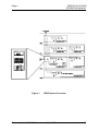
1
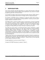
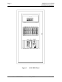
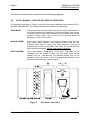
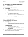
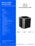
SIMPEX 4100 EWIS
OPERATOR MANUAL
Type 4100
EMERGENCY WARNING
and INTERCOMMUNICATION
SYSTEM (EWIS)
OPERATOR MANUAL
VOLUME 1 of 3
Document No.: 4100-M010A
May 1999
Issue 3.1
Page ii
SIMPLEX 4100 EWIS
OPERATOR MANUAL
GLOSSARY OF STANDARD TERMS
The following abbreviations are used throughout this manual:
ACF:
Ancillary control facility.
"Ackd":
Display abbreviation for acknowledged condition.
BGM
Background Music
ECP
Emergency Control Panel
EIS
Emergency Intercommunication System
EWIS
Emergency Warning and Intercommunication System
EWS
Emergency Warning System
FIP
Fire Indicator Panel
LCD:
Liquid Crystal Display
LED:
Light Emitting Diode
MECP
Master Emergency Control Panel
PA
Public Address
SECP
Secondary Emergency Control Panel
WIP
Warden Intercommunication Phone.
MANUFACTURERS DETAILS
APPROVALS: AUSTRALIAN STANDARD AS2220.1 (1989) amendment 1
SSL LISTING NUMBER afp-1174
The 4100 EWIS is manufactured by:
Simplex International Pty Ltd
140 Old Pittwater Road
Brookvale N.S.W 2100 Australia
ACN: 008 435 443
Phone: (02)-9466-2333
Fax: (02) 9939 2623
Notice: The contents of this document are subject to change without notice.
Document No.: 4100-M010A
May 1999
Issue 3.1
SIMPLEX 4100 EWIS
OPERATOR MANUAL
Page iii
AMENDMENTS TO 4100 OPERATOR MANUAL
ISSUE
SECTION/PAGES
AMENDED
DATE
AMENDED
1.0
New Manual
Aug 1993
2.0
Section 3 added
Convert to Word 97
Section 4, 5, 6, A & B
added, & updated
Glossary and
Manufacturers Details
updated
April 1994
3.0
3.1
COMMENTS
ECN No.
Original - File:
Update
information
March 1998
File
ewisop
May 1999
S.S.L. Listing
number added
RELATED DOCUMENTATION
This manual is part of a three volume set relating to the 4100 EWIS Option. The
following lists the documentation relating to the 4100 EWIS Option.
Volume 1
4100 EWIS - Operator Manual.
This manual describes the operating procedures for a typical 4100
EWIS. 4100 EWIS Operator Manual
Part No/Document No: 4100-M010
Volume 2
4100 EWIS - Installation Manual.
This manual describes the procedures for installing and commissioning
typical 4100 EWIS. 4100 EWIS Installation Manual
Part No/Document No: 4100-M011
Volume 3
4100 EWIS - Technical Manual.
This manual contains technical descriptions of the various components
of typical 4100 EWIS Panel. 4100 EWIS Technical Manual
Part No/Document No: 4100-M012
Document No.: 4100-M010A
May 1999
Issue 3.1
Page iv
SIMPLEX 4100 EWIS
OPERATOR MANUAL
TABLE OF CONTENTS
AMENDMENTS TO 4100 OPERATOR MANUAL .................................................................iii
RELATED DOCUMENTATION.......................................................................................................iii
COMPATIBLE BATTERIES ..................................................................................................vii
COMPATIBLE EQUIPMENT .................................................................................................vii
SPECIFICATION ..................................................................................................................viii
GENERAL ..................................................................................................................................... viii
EXPANSION MODULES ..............................................................................................................viii
Amplifiers. ................................................................................................................................ viii
Public Address (PA) and Background Music (BGM). .............................................................. viii
Warden Intercommunication Points (WIPs). .............................................................................ix
Strobe Control............................................................................................................................ix
Emergency Alarm Initiating Device............................................................................................ix
Power Supplies..........................................................................................................................ix
Audio Features. .........................................................................................................................ix
Audio Control LED/Switch Modules...........................................................................................ix
Fault Messages. ........................................................................................................................ix
1 INTRODUCTION ..................................................................................................................1
1.1 AUDIO FEATURES................................................................................................................... 3
1.1.1 Audio Control LED/Switch Module ................................................................................... 3
1.1.2 Fault Messages ................................................................................................................ 4
2 AUDIO OPERATIONS..........................................................................................................5
2.1 AUDIO CONTROL LED/SWITCH MODULE ............................................................................ 5
2.2 AUTO / MANUAL / ISOLATE KEY SWITCH OPERATION ...................................................... 6
2.3 ALL CIRCUIT ALERT SWITCH ................................................................................................ 7
2.4 SELECTIVE ZONE ALERT / EVACUATION SWITCHES ........................................................ 7
2.5 ALL CIRCUITS EVACUTAION SWITCH .................................................................................. 7
2.6 SELECTIVE ZONE EVACATION SWITCHES ......................................................................... 7
2.7 ALL CIRCUITS PA (TALK) SWITCH ........................................................................................ 8
2.8 SELECTIVE CIRCUITS PA (TALK) SWITCHES ...................................................................... 8
2.9 HOW TO OPERATE THE MICROPHONE ............................................................................... 9
2.10 HOW TO MANUALLY INITIATE AN ALERT / EVACUATION SIGNAL................................ 10
2.10.1 Alert Signal Operation .................................................................................................. 10
2.10.2 Evacuation Signal Operation ....................................................................................... 10
2.10.3 HOW TO OPERATE THE MICROPHONE DURING NON-ALARM CONDITIONS ................................ 11
2.11 DURATION OF THE ALERT SIGNAL .................................................................................. 11
3 EMERGENCY INTERCOMMUNICATION (WIP) OPERATION ........................................12
3.1 WIP CONTROL LED / SWITCH MODULE ............................................................................. 12
3.2 SELECTIVE ZONE WIP SWITCHES...................................................................................... 13
3.3 SELECTIVE ZONE MANNED / CLEARED............................................................................. 13
3.4 WIP OPERATION ................................................................................................................... 14
4 FAULT CONDITIONS.........................................................................................................15
4.1 HOW TO OPERATE THE PANEL DURING FAULT CONDITIONS ...................................... 15
4.3 ESSENTIAL FAULT CONDITION KEYS ................................................................................ 16
4.4 FAULT ACKNOWLEDGE KEY ............................................................................................... 17
Document No.: 4100-M010A
May 1999
Issue 3.1
SIMPLEX 4100 EWIS
OPERATOR MANUAL
Page v
5 SYSTEM TEST PROCEDURES.........................................................................................18
5.1 LAMP TEST ............................................................................................................................ 18
5.2 ALL CIRCUITS ALERT TEST ................................................................................................. 18
5.3 SELECTIVE ZONE ALERT / EVACUATION TEST ................................................................ 19
5.4 ALL CIRCUITS EVACUATION TEST ..................................................................................... 19
5.6 SELECTIVE ZONE EVACUATION TEST............................................................................... 19
5.7 ALL CIRCUITS PA (TALK) TEST ........................................................................................... 20
5.8 SELECTIVE CIRCUITS PA (TALK) TEST .............................................................................. 20
6 MAINTENANCE PROCEDURES .......................................................................................21
6.1 LEVEL 1 - MONTHLY TESTS................................................................................................. 21
6.2 LEVEL 2 – SIX MONTHLY TESTS ......................................................................................... 22
APPENDIX A - COMMISSION CHECKLIST.........................................................................23
APPENDIX B – FAULT CONDITIONS TABLES ..................................................................25
4100 LCD DISPLAY FAULT MESSAGES .................................................................................... 25
APPENDIX C - LIST OF INSTALLED EQUIPMENT.............................................................28
TABLE OF FIGURES
Figure 1
Figure 2
Figure 3
Figure 4
Figure 5
Figure 6
Figure 7
EWIS System Overview .............................................................................. x
4100 EWIS Panel ........................................................................................ 2
Operator Interface Panel ............................................................................. 4
Audio Control LED / Switch Panel ............................................................... 5
Key Switch Operation .................................................................................. 6
WIP Control LED / Switch Panel ............................................................... 12
Operator Interface Showing Fault Conditions............................................ 15
Document No.: 4100-M010A
May 1999
Issue 3.1
Page vi
SIMPLEX 4100 EWIS
OPERATOR MANUAL
PANEL DETAILS
panel sticker
4100 EWIS Panel
supplied by
Installation location
Contract/Job Number
As installed System
drawing number
Panel Installation date
Panel Commissioned date
Maintenance Company
Telephone
Service Contact
Document No.: 4100-M010A
May 1999
Issue 3.1
SIMPLEX 4100 EWIS
OPERATOR MANUAL
Page vii
COMPATIBLE BATTERIES
The following series of batteries are compatible with the 4100 System:
(1)
Power-Sonic PS12 series
(2)
Sonnenschien A200 series
(3)
Sonnenschien A300 series
(4)
Yuasa NP series
COMPATIBLE EQUIPMENT
(1)
Speakers - 100V Line
Simplex P/No. 2902-9794
Simplex P/No. 2902-9796
Simplex P/No. 2902-9830
Simplex P/No. 2902-9821
(2)
-
100mm 5 Watt multi-tapped
200mm 5 Watt multi-tapped
10W multi-tapped Horn Speaker
15W multi-tapped Horn Speaker
EIS - WIP Handset
Simplex P/No. 2084-9106 - WIP 4100 Evac
(3)
Emergency Alarm Initiating Devices
Simplex P/No. 2099-2020 - White MCP EWIS
Document No.: 4100-M010A
May 1999
Issue 3.1
Page viii
SIMPLEX 4100 EWIS
OPERATOR MANUAL
SPECIFICATION
GENERAL
System Capacity
Cabinet Size(mm)
Cabinet Material
Cabinet Finish
Cabinet Colour
Mounting
Configurable to suit building requirements
Dependent on system configuration
1.5mm Mild grade steel
Powder coated
Magnolia Ripple
Wall mount
Mains Input
Internal Power Supply
Standby Battery
Battery Charger
PSU Supervision
Temperature
Humidity
240V AC, +6%,-10%, 50Hz
24V DC @ 6.5A
24V sealed lead acid up 110Ah
27.6V DC (nominal) @ 3.5A,
Charger high/low, Battery low/fail
-5 C to 45 C
10% to 90% RH non-condensing.
EXPANSION MODULES
Amplifiers.
The 4100 EWIS option provides either 25 Watt or 50 Watt amplifiers as standard,
optional external higher power amplifiers can also be interfaced into the system. The
amplifiers have a bandwidth of 60Hz to 14.5KHz and a signal-to-noise ratio of better
than 66dB.
Each amplifier has its own on-board tone generator to provide Alert/Evacuation
tones as per AS2220. Stored verbal messages can also be utilised in conjunction
with the Evacuation tone sequence.
Amplifiers and speaker lines are supervised and monitored for fault conditions. In
the event of a short circuit line condition or an amplifier fault, the amplifiers will
automatically shutdown as a battery power saving measure. Once the fault is
cleared, the amplifiers will automatically restore to broadcast. Separate fault
reporting is provided to indicate amplifier fault, speaker line open circuit and speaker
line short circuit.
Public Address (PA) and Background Music (BGM).
A separate PA input line allows for the selection of either PA voice announcements
via the panel PA microphone or remote PA/background music. In the event of an
alarm condition, the remote PA/BGM input will be overridden by the Alert/Evacuation
sequence.
Document No.: 4100-M010A
May 1999
Issue 3.1
SIMPLEX 4100 EWIS
OPERATOR MANUAL
Page ix
Warden Intercommunication Points (WIPs).
Remote warden phones are connected to the system via WIP modules. Each WIP
module provides six (6) individual WIP circuits. Each WIP circuit is supervised for
open/short circuit condition.
Strobe Control.
A strobe driver module provides outputs for driving up to three (3) sets of two strobe
circuits. A separate circuit is provided for the ALERT strobe and the EVAC strobe.
Each strobe circuit is rated at 2 amps/24VDC and can drive up to ten (10) strobes.
Emergency Alarm Initiating Device.
Break Glass Alarm modules (BGA) provide eight (8) separate inputs per module for
interfacing to remote Emergency Alarm Initiating manual call points. Each input is
supervised for open and short circuit conditions.
Power Supplies.
Modular 10 amp power supplies are utilised, each with their own in-built battery
monitoring /charger circuit. The power supply/charger can charge batteries up to
110AHr capacity. Multiple power supplies/chargers are used where systems require
larger power supplies/battery configuration.
Audio Features.
The 4100 Voice Communications option provides automatic alert and evacuation
messages over pre-programmed speaker circuits during an alarm condition. Alert or
Evacuation messages may also be manually initiated either to all areas of a building or
to specific areas within the building. The dedicated system microphone provides live
voice message delivery to any area within the building. Two-way communications is
available with the Warden Intercommunication Phone system.
Audio Control LED/Switch Modules.
Control of audio functions is performed by operating switches on LED/Switch modules,
which are mounted on the 4100 Front Panel. The functions and quantity of the
LED/Switch modules depend on the desired options and the number of zones in the
audio system. Labels are inserted into the slots on the LED/Switch modules to identify
the function of each switch and LED.
Standard switches on the Audio Control LED/Switch Module are momentary switches.
LED indicator modules are provided to annunciate alarm inputs from the Fire Indicating
Panel or Manual Call Point.
Fault Messages.
Fault messages from the audio system are shown on the alphanumeric display and
entered into the Fault Log. The operator uses the operator interface panel keys to
acknowledge the fault, silence the alarm, and reset the fault condition. The operator
can also use the panel keys to scroll through the fault history log or download the log to
a printer if installed on the system.
Document No.: 4100-M010A
May 1999
Issue 3.1
Page x
SIMPLEX 4100 EWIS
OPERATOR MANUAL
Figure 1
Document No.: 4100-M010A
EWIS System Overview
May 1999
Issue 3.1
SIMPLEX 4100 EWIS
OPERATOR MANUAL
1
Page 1
INTRODUCTION
This manual describes operating procedures for a typical 4100 Emergency Warning
and Intercommunication System (EWIS) Panel. Applications may vary due to custom
programming and local code requirements.
The Simplex Emergency Warning and Intercommunication System (EWIS) option is
based on the time tested “state-of-the-art” Simplex 4100 Fire Panel architecture.
The Simplex 4100 EWIS system comprises an equipment cubicle which houses a
number of electronic sub-assemblies including amplifiers, monitoring circuits, power
supplies batteries and operator controls.
The EWIS system is normally located in the Fire Control Room or Foyer of a building
and connects to groups or zones of speakers located throughout the building (in
accordance with the building code of Australia). Its function is to broadcast a series
of warning tones throughout the building in the event of a fire alarm or other
emergency, thereby enabling the orderly evacuation of building occupants.
The EWIS may also contain an intercommunication system comprising a master
telephone-type handset located at the main panel connected to remote telephone
handsets (WIPs) located throughout the speaker zone. The purpose of the
Intercommunication system is to assist in the evacuation of a building by enabling
communication to take place between the Chief Warden or Fire Control Officer
directing the evacuation process from the main panel and the Floor Wardens located
on each building floor.
Today’s project sizes and extremely high public population demand comprehensive
early-warning fire detection and EWIS systems which provide accurate and timely
information for response to emergency situations. Simplex offers its most advanced
product range to maximise life safety.
A typical application overview is shown in Figure 1.
A typical 4100 EWIS Panel layout is shown in Figure 2
Document No.: 4100-M010A
May 1999
Issue 3.1
Page 2
SIMPLEX 4100 EWIS
OPERATOR MANUAL
Figure 2
Document No.: 4100-M010A
4100 EWIS Panel
May 1999
Issue 3.1
SIMPLEX 4100 EWIS
OPERATOR MANUAL
Page 3
This section covers the following topics:
General Audio System information
All Circuits Alert/Action/PA operation
Selective Alert/Action/PA operation
1.1
AUDIO FEATURES
The 4100 EWIS option provides automatic alert and evacuation messages over preprogrammed speaker circuits during an alarm condition. Alert or Evacuation messages
may also be manually initiated either to all areas of a building or to specific areas within
the building. The dedicated system microphone provides live voice message delivery to
any area within the building. Two-way communications are available with the Warden
Intercommunication Phone system (WIPs).
1.1.1 Audio Control LED/Switch Module
Control of audio functions is performed by operating switches on LED/Switch modules
which are mounted on the 4100 Front Panel refer Figure 2. The functions and quantity
of the LED/Switch modules depend on the desired options and the number of zones in
the audio system. Coloured Labels are inserted into the slots on the LED/Switch
modules to identify the function of each switch and LED.
Standard switches on the Audio Control LED/Switch Module are momentary switches.
LED indicator modules are provided to annunciate alarm inputs from the Fire Indicating
Panel or Manual Call Point.
Document No.: 4100-M010A
May 1999
Issue 3.1
Page 4
SIMPLEX 4100 EWIS
OPERATOR MANUAL
1.1.2 Fault Messages
Fault messages from the audio system are shown on the alphanumeric display and
entered into the Fault Log. The operator uses the operator interface panel keys to
acknowledge the fault, silence the alarm, and reset the fault condition (refer Figure 3).
See Section 4, Fault Conditions for required operations.
Figure 3
Document No.: 4100-M010A
Operator Interface Panel
May 1999
Issue 3.1
SIMPLEX 4100 EWIS
OPERATOR MANUAL
2
Page 5
AUDIO OPERATIONS
This section describes the Audio features and operation of the 4100 EWIS System.
2.1
AUDIO CONTROL LED/SWITCH MODULE
Figure 4 shows the Emergency Warning System Audio Control LED/Switch Modules
controlling the following functions:
AUTO/MANUAL/ISOLATE KEYSWITCH OPERATION
ALL CIRCUITS ALERT, EVACUATION
SELECTIVE CIRCUITS ALERT, EVACUATION
ALL CIRCUITS PUBLIC ANNOUNCEMENTS (P.A.)
SELECTIVE CIRCUITS PUBLIC ANNOUNCEMENTS (P.A.)
CANCEL SELECTED TONE / PA OPERATION
Figure 4
Document No.: 4100-M010A
Audio Control LED / Switch Panel
May 1999
Issue 3.1
Page 6
SIMPLEX 4100 EWIS
OPERATOR MANUAL
The function of each switch is explained in the following paragraphs.
2.2
AUTO / MANUAL / ISOLATE KEY SWITCH OPERATION
The keyswitch as shown in Figure 5 provides three panel operating modes namely AUTO,
MANUAL AND ISOLATE. The following describes the operation of each mode:
AUTO MODE:
This is the normal operating mode of the panel. In this mode initiation of
the Alert/Evacuation tone sequence is done automatically upon receipt
of an alarm input from the Fire Indicating Panel or Manual Call Points
located at remote WIPs. The key can only be removed when the
keyswitch is in the AUTO position.
MANUAL MODE:
In this mode, panel operation is controlled manually using the front
panel audio control switches. Alarm signals received from the Fire
Indicating panel have no control over panel operation. Turning the
keyswitch from AUTO to MANUAL mode while the Alert/Evacuation
tones are being broadcast, will turn off all tones on all zones.
ISOLATE MODE:
This mode disables broadcasting of the Alert, Evacuation or PA
messages over the speaker circuits. The front panel audio control
switches can be operated but the selected function will not be
activated. This mode can be used to demonstrate the operation of the
panel without activating the relevant outputs.
Figure 5
Document No.: 4100-M010A
Key Switch Operation
May 1999
Issue 3.1
SIMPLEX 4100 EWIS
OPERATOR MANUAL
2.3
Page 7
ALL CIRCUIT ALERT SWITCH
This switch is used to output the ALERT (ALT) tone to all of the speaker circuits.
Each switch is a momentary switch that has an LED to indicate switch operation. Pushing the
switch to the momentary UP or DOWN position, outputs the ALERT tone to all speaker circuits.
The yellow LED tracks the ALERT tone in progress.
To cancel the ALL ZONE ALERT tone, push the associated momentary switch in the
UP or DOWN position.
2.4
SELECTIVE ZONE ALERT / EVACUATION SWITCHES
These switches are used to output the ALERT tone to a selected evacuation zone.
Each switch is a momentary switch that has an associated LED to indicate switch operation.
Pushing the switch to the momentary UP or DOWN position outputs the ALERT tone to the
selected Evacuation zone. The yellow LED tracks the ALERT tone in progress.
To cancel the selected ALERT Tone, push the associated momentary switch in the UP
or DOWN position.
2.5
ALL CIRCUITS EVACUTAION SWITCH
This switch is used to output the EVACUATION (EVAC) tone to all of the speaker circuits.
Each switch is a momentary switch that has an associated LED to indicate switch operation.
Pushing the switch to the momentary UP or DOWN position, outputs the EVACUATION tone
to all speaker circuits. The red LED tracks the EVACUATION tone in progress.
To cancel the ALL ZONE EVACUATION tone, push the associated momentary switch
in the UP or DOWN position.
2.6
SELECTIVE ZONE EVACATION SWITCHES
These switches are used to output the EVACUATION tone to a selected evacuation zone.
Each switch is a momentary switch that has an associated LED to indicate switch operation.
Pushing the switch to the momentary UP or DOWN position outputs the EVACUATION tone to
the selected Evacuation zone. The red LED tracks the EVACUATION tone in progress.
To cancel the selected EVACUATION Tone, push the associated momentary switch
in the UP or DOWN position.
Document No.: 4100-M010A
May 1999
Issue 3.1
Page 8
2.7
SIMPLEX 4100 EWIS
OPERATOR MANUAL
ALL CIRCUITS PA (TALK) SWITCH
This switch is used to turn ON all speaker circuits to broadcast public address announcements.
Each switch is a momentary switch that has an associated led with it to indicate switch
operation.
The momentary UP or DOWN position of the switch turns all speaker circuits ON. The
associated LED (red) is ON when all the speaker circuits are activated for Public address (PA).
Announcements can now be made using the panel microphone while the Mike Talk Switch is
held in.
To cancel the ALL ZONE PA, push the associated momentary switch in the UP or
DOWN position.
2.8
SELECTIVE CIRCUITS PA (TALK) SWITCHES
The zone PA Select Switches are normally used to turn ON individual zone speaker circuits.
Each switch is a momentary switch that has an associated LED to indicate switch operation.
The momentary UP or DOWN position of the switch turns the selected speaker circuit ON.
The associated LED (green) is ON when the speaker is activated for Public address (PA).
Announcements can now be made using the panel microphone while the Mike Talk Switch is
held in.
To cancel the selected zone PA mode, push the associated momentary switch in the
UP or DOWN position.
Document No.: 4100-M010A
May 1999
Issue 3.1
SIMPLEX 4100 EWIS
OPERATOR MANUAL
2.9
Page 9
HOW TO OPERATE THE MICROPHONE
During AUTO mode, operate the microphone in the following manner.
1.
Press the [ALARM ACK] key, if a Fire Alarm signal has been detected by the
Evacuation panel. This will silence the panel beeper and acknowledge the alarm
condition.
2.
To talk to ALL areas:
Turn Evac keyswitch to MANUAL position. Operate the momentary ALL ZONE PA
switch wait for the RED LED to light up and go to Step 3.
To talk to SPECIFIC areas:
Turn Evac keyswitch to MANUAL position. Operate the momentary PA switch for the
selected PA zone wait for the GREEN LED to light up and go to Step 3.
3.
Remove the Microphone from the Microphone clip; press and hold-in the Talk switch on
the microphone.
4.
Make the appropriate announcement. (See note below)
5.
When finished, unkey the Microphone and place it back onto the Microphone holding
clip.
6.
Turn off ALL ZONES PA or Selected zone PA by pushing the associated
momentary switch in the UP or DOWN position.
7.
If alarm signals are present, press the SYSTEM RESET key to reset the alarm
condition and return the keyswitch to the AUTO position.
NOTE:
The microphone used on the panel is a special noise cancelling
microphone. When making PA announcements, the operator must
hold the microphone very close too and directly in front of your
mouth and speak in a loud clear voice. Failure to do so will result in
loss of volume of the PA announcements.
Document No.: 4100-M010A
May 1999
Issue 3.1
Page 10
2.10
SIMPLEX 4100 EWIS
OPERATOR MANUAL
HOW TO MANUALLY INITIATE AN ALERT / EVACUATION SIGNAL
2.10.1
Alert Signal Operation
To manually initiate an ALERT signal, do the following:
1.
To alert ALL areas:
a.
b.
Turn Evac keyswitch to MANUAL position.
Operate the momentary UP or DOWN position of the ALL ZONES
ALERT Switch. This will broadcast the alert tone to all areas.
To alert specific areas:
a.
b.
2.
Turn Evac keyswitch to MANUAL position.
Operate the momentary UP or DOWN position of the required
area ZONE ALERT Switch. This will broadcast the alert tone to
the selected area.
To turn OFF the ALERT tone to ALL ZONES or SELECTED ZONES, push the
associated momentary switch in the UP or DOWN position.
2.10.2
Evacuation Signal Operation
To manually initiate an evacuation signal, do the following:
1.
To evacuate ALL areas:
a.
b.
Turn Evac keyswitch to MANUAL position.
Operate the momentary UP or DOWN position of the ALL ZONES
EVAC Switch. This will broadcast the evacuation tone to all areas.
To evacuate specific areas:
a.
b.
2.
Turn Evac keyswitch to MANUAL position.
Operate the momentary UP or DOWN position of the required
area ZONE EVAC Switch. This will broadcast the evacuation tone
to the selected area.
To turn OFF the EVAC tone to ALL ZONES or SELECTED ZONES, push the
associated momentary switch in the UP or DOWN position.
Document No.: 4100-M010A
May 1999
Issue 3.1
SIMPLEX 4100 EWIS
OPERATOR MANUAL
2.10.3
Page 11
How to Operate the Microphone during Non-Alarm Conditions
During non-alarm conditions, operate the microphone in the following manner.
1.
To talk to ALL areas:
Turn Evac keyswitch to the MANUAL position. Push the momentary ALL
ZONES PA Switch UP or DOWN. This will select All Zones for PA
announcement. Now go to Step 2.
To talk to SPECIFIC areas:
Turn Evac keyswitch to the MANUAL position. Push the desired ZONE PA
SWITCHES (momentary UP or DOWN position) to select the desired PA
ZONE.
2.
Remove the Microphone from the microphone holding clip and hold close to
your mouth; press and hold-in the push-to-Talk switch located on the
microphone.
3.
Make the appropriate announcement. (refer note below)
4.
When finished, unkey the Microphone and replace it in on the microphone
holding clip.
5.
Turn off ALL ZONES PA or Selected zone PA by pushing the associated
momentary switch in the UP or DOWN position.
6.
Return the EVAC keyswitch to the AUTO position
NOTE:
2.11
The microphone used on the panel is a special noise cancelling
microphone. When making PA announcements, the operator must hold
the microphone very close too and directly in front of your mouth and
speak in a loud clear voice. Failure to do so will result in loss of volume of
the PA announcements.
DURATION OF THE ALERT SIGNAL
If the panel has not been programmed without the automatic cascade evacuation
sequence then the duration of the alert signal defaults to 600 seconds (10 minutes).
This means that in the event of an alarm signal and the panel is in AUTO mode, then
the ALERT tone will sound for a period of 600 seconds and then automatically go to a
continuous EVACuation tone unless the panel is placed in manual control by turning the
keyswitch to the MANUAL position. Turning the keyswitch to the MANUAL position will
cancel any tones being broadcast.
Document No.: 4100-M010A
May 1999
Issue 3.1
Page 12
3
SIMPLEX 4100 EWIS
OPERATOR MANUAL
EMERGENCY INTERCOMMUNICATION (WIP)
OPERATION
The Emergency Intercommunication System provides telephone style communication
from the master warden intercommunication phone (WIP) on the master panel to
remote telephone type WIP handsets located remotely in the evacuation zones.
The operation of the WIP system is entirely independent of the Emergency Warning
System and is not affected by the operation of the AUTO/MANUAL/ISOLATE
keyswitch.
3.1
WIP CONTROL LED / SWITCH MODULE
Figure 6 shows the LED/SWITCH WIP modules controlling the following functions:
SELECTIVE ZONE WIP OPERATION
SELECTIVE ZONE MANNED/CLEARED OPERATION
Figure 6
Document No.: 4100-M010A
WIP Control LED / Switch Panel
May 1999
Issue 3.1
SIMPLEX 4100 EWIS
OPERATOR MANUAL
3.2
Page 13
SELECTIVE ZONE WIP SWITCHES
These switches are used to call or answer a remote WIP located in an evacuation zone.
Each switch is a momentary switch that has an associated LED to indicate WIP
operation.
Pushing the switch to the momentary UP position establishes connection to a remote
WIP. Pushing the switch again in the momentary DOWN position cancels conversation
with the remote WIP.
The RED LED tracks the WIP operation as follows:
-
Red LED flashing means call waiting from remote WIP.
-
Red LED steady means connection established to remote WIP.
To cancel conversation with a remote WIP, push the momentary WIP switch to the
DOWN position. The red WIP LED will turn off to indicate connection is cancelled. Then
replace master WIP handset onto its cradle.
3.3
SELECTIVE ZONE MANNED / CLEARED
These switches function as memory buttons and are used as a log indicator by the
operator to log whether an evacuation zone is manned.
Each switch is a three position switch, which functions as follows:
UP or Down
Position:
Pushing the switch to the UP or DOWN position will turn the
GREEN LED on to log the fact that an evacuation WIP point is
manned. Pushing switch UP or DOWN again will turn LED off.
CENTRE Position: No Operation.
Document No.: 4100-M010A
May 1999
Issue 3.1
Page 14
3.4
SIMPLEX 4100 EWIS
OPERATOR MANUAL
WIP OPERATION
To operate the WIPs do the following:
1.
2.
To Call a WIP from the Main panel:
a.
Lift the master WIP Handset from its cradle.
b.
Push the required zone WIP switch to the momentary UP
position. The remote WIP will ring and the RED LED will
go steady when the REMOTE WIP is answered.
c.
To cancel call, push the selected zone WIP switch to the
momentary DOWN position. The RED led will turn off.
Now replace the master WIP handset to its cradle.
To answer a WIP CALL:
a.
The RED WIP zone LED on the main panel will flash when
a remote is lifted of its cradle.
b.
To answer the call at the main panel, Lift the master WIP
handset of its cradle and push the Zone WIP switch
associated with the flashing LED to the momentary UP
position to establish the connection.
c.
To cancel call, push the selected zone WIP switch to the
momentary DOWN position. The RED led will turn off.
Now replace the master WIP handset to its cradle.
Document No.: 4100-M010A
May 1999
Issue 3.1
SIMPLEX 4100 EWIS
OPERATOR MANUAL
4
Page 15
FAULT CONDITIONS
When a fault condition is detected by the EWIS System, the condition is indicated on
the main 4100 EWIS PANEL as follows:
- Yellow "SYSTEM FAULT" LED is flashing.
- Tone-alert is on steady.
- Alphanumeric display shows the following:
**FAULT**
ALARMS = 0
Press ACK to review.
ISOLATED = 0
FAULT = 1
The panel has a yellow fault LED which will light whenever a fault is present in the
system. When a fault occurs, the LED will flash, the tone-alert sounds steady, and a
fault message will be displayed on the alphanumeric display. The fault LED will glow
steady and the tone-alert silences when the <FAULT ACK> key is pressed.
When Global Acknowledge is used, and the fault clears, the system automatically
clears without user intervention. After approximately 30 seconds, the system should
display "SYSTEM IS NORMAL followed by time and date".
SIMPLEX AUSTRALIA
SYSTEM IS
NORMAL
08:23:43
FRI 13 FEB 98
4.1
HOW TO OPERATE THE PANEL DURING FAULT CONDITIONS
(Yellow LED Is Flashing And Tone-Alert Is On Steady)
Figure 7
Operator Interface Showing Fault Conditions
Document No.: 4100-M010A
May 1999
Issue 3.1
Page 16
A.
SIMPLEX 4100 EWIS
OPERATOR MANUAL
Unlock and open the panel door. The alphanumeric display will show the fault
condition.
**FAULT**
ALARMS = 0
B.
Press <ACK> to review points
ISOLATED = 0
FAULT = 1
Press the <FAULT ACK> key under the flashing yellow LED.
The
alphanumeric display will show area and type of fault. The tone alert will
silence and the yellow LED will glow steady.
FIRST FLOOR EAST WING
AZF1
ZONE1
OPEN CIRCUIT FAULT SPEAKER LINE
C.
Read the alphanumeric display, then investigate the problem to determine its
cause.
-
Restore or replace the defective device in accordance with device
instructions.
-
The fault will automatically clear when the problem has been corrected.
-
After a delay, the alphanumeric display should show:
SIMPLEX AUSTRALIA
NORMAL
8:23:43
SAT 14 JAN 98
SYSTEM IS
NOTE: There are 5 types of fault conditions associated with the EWIS system.
•
•
•
•
•
4.3
Open Circuit Speaker Line
Short Circuit Speaker Line with Amplifier Off
Amplifier Failure
Open Circuit WIP Line
Short Circuit WIP Line
ESSENTIAL FAULT CONDITION KEYS
The essential keys for
<SYSTEM RESET> keys.
Document No.: 4100-M010A
fault
conditions
are
May 1999
<FAULT
ACK>,
and
the
Issue 3.1
SIMPLEX 4100 EWIS
OPERATOR MANUAL
4.4
Page 17
FAULT ACKNOWLEDGE KEY
The <FAULT ACK> key is used to scroll through the various displays on the
alphanumeric display. It also controls the Fault LEDs and the tone-alert. The
<FAULT ACK> key is located directly under the fault LED. Pressing the <FAULT
ACK> key will cause the LED to change from flashing to on steady and silence the
tone-alert. When the <FAULT ACK> key is pressed, it will:
A. Acknowledge the displayed point or acknowledge all points on the list (Global
Acknowledge).
B. Scroll the points chronologically after all points have been acknowledged.
When Global Acknowledge is used on the 4100 system, a single key press will
acknowledge all fault changes in the system. If status change information is
required, the user may review this data (after a delay) by pressing the <ACK>
key and reading the total number of fault changes on the alphanumeric display.
If a fault condition has been acknowledged with the <ACK> key and further
unacknowledged fault conditions remain in the system, the tone-alert continues
to sound and the next status change is shown on the alphanumeric display.
NOTE: Normally, points may not require acknowledgment and do not latch. If the
system does not clear, read the display, then check for devices still in fault
(manual call points, strobe etc.).
Document No.: 4100-M010A
May 1999
Issue 3.1
Page 18
5
SIMPLEX 4100 EWIS
OPERATOR MANUAL
SYSTEM TEST PROCEDURES
NOTE: These procedures should be followed when the system is installed and
during periodic testing as required by code. Check local codes to determine
how frequent your system should be tested. Always inform appropriate
personnel that you will be testing the system (Building personnel, Fire
Brigade, etc.).
Before proceeding with the following tests, switch the EWIS system into MANUAL
MODE, by turning the KEY SWITCH to MANUAL on the EWIS panel.
Once the test have been completed, switch the EWIS system back to AUTO MODE,
by turning the KEY SWITCH to AUTO on the EWIS panel.
5.1
LAMP TEST
The “LAMP TEST” push-button on the operator interface panel is used to determine
local lamp failures within the system. Lamps on the 4100 operator interface panel
illuminate along with the five function and acknowledge LEDs. All segments on the
LCD also change to squares. Perform the following procedures to determine lamp
failures.
1. Press the “LAMP TEST” push-button. All LEDs should illuminate (lamps
should stay illuminated as long as the push-button is depressed). Holding
the push-button in for more than 3 seconds will test the tone-alert.
2. Perform an individual lamp test on all remote LCD annunciators using the
key switch on the operator interface panel.
3. If you find defective lamps/LEDs, contact your local Simplex branch office.
5.2
ALL CIRCUITS ALERT TEST
Push the ALL CIRCUIT ALERT switch momentary UP or DOWN.
ALERT TONE should be an output on all speaker circuits.
To cancel, push the associated momentary switch in the UP or DOWN position.
Document No.: 4100-M010A
May 1999
Issue 3.1
SIMPLEX 4100 EWIS
OPERATOR MANUAL
5.3
Page 19
SELECTIVE ZONE ALERT / EVACUATION TEST
Push the switch momentary UP or DOWN for the selected zone.
ALERT TONE should be an output on all speaker circuits for the selected
zone.
To cancel, push the associated momentary switch in the UP or DOWN position.
5.4
ALL CIRCUITS EVACUATION TEST
Push the ALL CIRCUIT EVACUATION switch momentary UP or DOWN.
EVACUATION TONE should be an output on all speaker circuits.
To cancel, push the associated momentary switch in the UP or DOWN position.
5.6
SELECTIVE ZONE EVACUATION TEST
Push the switch momentary UP or DOWN for the selected zone.
EVACUATION TONE should be an output on all speaker circuits for the
selected zone.
To cancel, push the associated momentary switch in the UP or DOWN position.
Document No.: 4100-M010A
May 1999
Issue 3.1
Page 20
5.7
SIMPLEX 4100 EWIS
OPERATOR MANUAL
ALL CIRCUITS PA (TALK) TEST
Push the ALL CIRCUIT PA switch momentary UP or DOWN.
The associated Green LED is should be switched ON.
All the PA speaker circuits are activated.
Perform a test announcement. The announcement should be an output on all
speaker circuits.
To cancel, push the associated momentary switch in the UP or DOWN position.
5.8
SELECTIVE CIRCUITS PA (TALK) TEST
Push the switch momentary UP or DOWN for the selected zone.
The associated Green LED is should be switched ON.
The PA speaker circuits are activated, for the selected zone.
Perform a test announcement. The announcement should be an output on all
speaker circuits, for the selected zone.
To cancel, push the associated momentary switch in the UP or DOWN position.
Document No.: 4100-M010A
May 1999
Issue 3.1
SIMPLEX 4100 EWIS
OPERATOR MANUAL
6
Page 21
MAINTENANCE PROCEDURES
It is a requirement of AS1851 - Part 10, The Standards Association of Australia Code
for Maintenance of Fire Protection Equipment – Emergency Warning and
Intercommunications in buildings, that tests be carried out to ensure the system is
fully functional.
6.1
LEVEL 1 - MONTHLY TESTS
The following inspection and testing procedures should be carried out each month:
(a)
Inform all building occupants that testing is to take place.
(b)
Visually check that the installation and its components are not damaged.
(c)
Where the system is associated with an alarm system. Perform a simulated
alarm call, operating any one of the alarm switches. Check that an ‘alert’
alarm appears at every ECP and at the appropriate zones. Check that EWIS
operation is automatically initiated.
(d)
Simulate an emergency condition at each control panel by setting the key
switch to ‘MANUAL’, then operating function switches to each zone
separately. At the same time, test operation of the emergency
intercommunication system.
(e)
Check the operation of all audible and visual indicators at each ECP.
(f)
Check that all control switches are returned to normal operating positions at
the control panels.
(g)
Check battery electrolyte level where applicable, and battery terminals for
corrosion.
(h)
Return all panel switches and controls to their normal operating position.
(i)
Inform the building occupants that the testing has concluded.
(j)
Record the completion of tests in the logbook, noting any defects and
remedial action required. Ensure the owner signs the report.
Document No.: 4100-M010A
May 1999
Issue 3.1
Page 22
6.2
SIMPLEX 4100 EWIS
OPERATOR MANUAL
LEVEL 2 – SIX MONTHLY TESTS
The Level 2 tests shall consist of all the inspection and testing procedures specified
in the previous clause and the following. These shall be carried out every 6 months.
(a)
Visually check the installation, location and siting of all equipment against the
system installation records. Record and report any discrepancy found
between the site records and the actual installation.
(b)
Check battery float charge voltage and current. These should be within
specified tolerances.
(c)
Carry out level 1 maintenance procedure as described in section 6.1
(d)
Disconnect the a.c. mains and measure the standby battery voltage under full
load conditions. The battery voltage shall be not less the 95% of the nominal
voltage. If less than 95% of the nominal voltage, the battery shall be tested
and / or replaced.
(e)
Reconnect the a.c mains and measure the current from the battery charger.
This current shall be within specified tolerances.
(f)
Measure and record the audible sound level in each zone. Check that it is in
accordance with previous measurements.
(g)
If visual warning lights are installed, check that they operate, and that the
flash rate is between 60 and 120 flashes per minute.
(h)
Record the completion of tests in the logbook, noting any defects and
remedial action required. Ensure the owner signs the report.
Document No.: 4100-M010A
May 1999
Issue 3.1
SIMPLEX 4100 EWIS
OPERATOR MANUAL
Page 23
APPENDIX A - COMMISSION CHECKLIST
JOB NAME:
............................................................................................................
JOB NUMBER: ............................................................................................................
PANEL SERIAL NUMBER: ...........................................................................................
Please place a tick in the space provided if check is correct. If not please give
details.
Panel Check List
Y
N
Cabinet undamaged (no paint chips, door aligned) .................................
U
U
U
U
U
U
Power Point fitted and wired correctly. ....................................................
All cabinet earths wired correctly and securely fitted...............................
Battery Capacity ......................................................................................
________
U
U
U
U
Power Up
Y
N
Charger output voltage at BATT +27.6VDC (@ 20 deg) .........................
U
U
All Print Circuit Boards securely fitted .....................................................
Identification Label Completed ................................................................
Quiescent panel current from battery (Mains Isolated)............................
Lamp Test OK .........................................................................................
Display LEDs aligned and all intensities similar.......................................
Function keys aligned and operate easily ...............................................
Document No.: 4100-M010A
May 1999
________
U
U
U
U
U
U
Issue 3.1
Page 24
SIMPLEX 4100 EWIS
OPERATOR MANUAL
Manual Mode Test – Each Zone
Y
N
Alert Tone OK .........................................................................................
U
U
U
U
U
U
U
U
U
U
U
U
U
U
U
U
U
U
U
U
Auto Mode Test
Y
N
Time delays operate as programmed......................................................
U
U
U
U
U
U
Evac Tone OK.........................................................................................
PA Speech OK ........................................................................................
Visual Output OK ....................................................................................
Fault Modes Operating Correctly ............................................................
- WIP Lines - O/C & S/C ...................................................................
- Speaker lines - O/C & S/C ..............................................................
- Strobe lines - O/C & S/C.................................................................
- FIB lines - O/C ................................................................................
- BGA lines - O/C ..............................................................................
Passed 24 hour burn-in period ................................................................
TEST COMPLETED, passed Q/A check.................................................
Name of Tester .......................................................................................
Signature.................................................................................................
Date of Test.............................................................................................
Document No.: 4100-M010A
May 1999
Issue 3.1
SIMPLEX 4100 EWIS
OPERATOR MANUAL
Page 25
APPENDIX B – FAULT CONDITIONS TABLES
4100 LCD DISPLAY FAULT MESSAGES
IF THE LCD DISPLAYS
POSSIBLE CAUSE
SOLUTION
•
•
Speaker cabling fault.
Open circuit cable.
•
Check as instructed in
installation manual.
•
No EOL resistor.
•
Fit 10k EOL resistor.
•
No DC isolation
capacitor fitted
(incorrect speaker
type).
•
Fitted capacitors or
change speaker.
•
•
Speaker cabling fault.
Short circuit cable.
•
Check as instructed in
installation manual.
•
No EOL resistor.
•
Fit 10k EOL resistor.
•
No DC isolation
capacitor fitted,
(incorrect speaker
type).
•
Fitted capacitors or
change speaker.
•
Faulty amplifier
•
Replace amplifier.
•
Blown fuse.
•
Replace fuse. 5 amp
3AG.
•
Faulty Ribbon Cable.
•
Replace Ribbon Cable.
OPEN CIRCUIT WIP LINE •
•
Speaker cabling fault.
Open circuit cable.
•
Check as instructed in
installation manual.
•
No EOL resistor.
•
Fit 10k EOL resistor.
•
•
Speaker cabling fault.
Open circuit cable.
•
Check as instructed in
installation manual.
•
No EOL resistor.
•
Fit 10k EOL resistor.
OPEN CIRCUIT FAULT
SPEAKER LINE
SHORT CIRCUIT FAULT
SPEAKER LINE WITH
AMPLIFIER OFF
AMPLIFIER FAILURE
SHORT CIRCUIT
WIP LINE
Document No.: 4100-M010A
May 1999
Issue 3.1
Page 26
SIMPLEX 4100 EWIS
OPERATOR MANUAL
IF THE LCD DISPLAYS
POSSIBLE CAUSE
SOLUTION
•
•
Cabling fault.
Open circuit cable.
•
Check as instructed in
installation manual.
•
No EOL resistor.
•
Fit 3k3 EOL resistor.
CARD XX
POWER
SUPPLY / CHARGER
•
Mains at Distribution •
board is OFF.
AC VOLTAGE
ABNORMAL
•
Mains Switch is OFF.
•
Turn Mains Switch ON.
•
Mains Fuse Blown.
•
Replace Fuse 8 Amp.
OPEN CIRCUIT
BGA INPUTS
CARD XX SWITCHED TO •
BATTERIES
•
BATTERY LOW
Mains at Distribution •
board is OFF.
Mains Power Failure.
Turn Power ON, check
for mains on indicator
when power is
returned.
•
Mains Switch off.
•
Turn Mains Switch ON.
•
Mains Fuse Blown.
•
Replace Fuse 8 Amp.
•
Mains Fail.
•
Reference mains on
indicator, and System
on batteries. Fault
status.
•
High volts:
Charger output volts
above 28.5 volts.
•
Replace Power Supply.
•
Low volts:
Charger output volts
below 24.5 volts.
•
Replace Power Supply.
•
Batteries fault:
Voltage below 24.5
volts
•
Replace Batteries
•
Batteries Disconnected
•
Connected Batteries
BATTERY DISCHARGED
BATTERY CHARGER
CAPACITY XX
Document No.: 4100-M010A
Turn Power ON.
May 1999
Issue 3.1
SIMPLEX 4100 EWIS
OPERATOR MANUAL
Page 27
FAULT / STATUS
NETWORK HAS FAILED
NETWORK GROUND
FAILED
POSSIBLE CAUSE
•
Section of the RS 485
loop faulty or
disconnected from
module.
NETWORK IS
OPERATING IN
DEGRADED STATE *7
Document No.: 4100-M010A
May 1999
SOLUTION
•
Check section and
termination, or field
wiring.
•
Check internal comms
connections.
•
Ensure all modules are
plugged in.
Ensure modules are
installed in correct
order.
Issue 3.1
Page 28
SIMPLEX 4100 EWIS
OPERATOR MANUAL
APPENDIX C - LIST OF INSTALLED EQUIPMENT
Evacuation
Zone
1
2
3
4
5
6
7
8
9
10
11
12
13
14
15
16
17
18
19
20
21
22
23
24
25
26
27
28
29
30
31
32
33
34
35
36
37
38
39
40
Fire
Zone
Loud Speaker
Power
Total
Qty
Tap
Load
Document No.: 4100-M010A
Amplifier
Total
Qty
Rating
May 1999
Visible Signals
A
E
WIPs
Qty
Issue 3.1
SIMPLEX 4100 EWIS
OPERATOR MANUAL
Evacuation
Zone
41
42
43
44
45
46
47
48
49
50
51
52
53
54
55
56
57
58
59
60
Fire
Zone
Page 29
Loud Speaker
Power
Total
Qty
Tap
Load
Document No.: 4100-M010A
Amplifier
Total
Qty
Rating
May 1999
Visible Signals
A
E
WIPs
Qty
Issue 3.1
Page 30
SIMPLEX 4100 EWIS
OPERATOR MANUAL
This page intentionally left blank
Document No.: 4100-M010A
May 1999
Issue 3.1