1
38/9 Hoyle Ave
Castle Hill NSW 2154
T: 61 2 9680 7944
F: 61 2 9680 7955
[email protected]
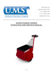
POWER PUSHER
OPERATION AND SERVICE MANUAL
~ 1 ~ Contents
SAFE OPERATION ........................................................................................................................................ 3 COMMISSIONING .......................................................................................................................................... 3 HAZARDS....................................................................................................................................................... 3 MAINTENANCE.............................................................................................................................................. 3 MAINTENANCE & ROUTINE CHECKS ......................................................................................................... 4 INSPECTION OF MECHANICAL PARTS ...................................................................................................... 4 BATTERIES: removal, replacement and re-charging ..................................................................................... 4 FUSES ............................................................................................................................................................ 5 CHAIN ADJUSTMENT ................................................................................................................................... 5 LUBRICATION................................................................................................................................................ 5 CLEANING ..................................................................................................................................................... 5 CONTROLS AND OPERATION ..................................................................................................................... 5 MAIN DC POWER SWITCH ........................................................................................................................... 5 ROTARY CONTROLS – SPEED & DIRECTION OF MOVEMENT ................................................................ 6 POWER INDICATOR and Low Battery “lock-out” function ............................................................................. 6 ANTI-CRUSHING SAFETY FEATURE: (“BELLY SWITCH”) ......................................................................... 6 ANTI - RUNAWAY FEATURE ........................................................................................................................ 6 FREE WHEEL HUBS ..................................................................................................................................... 7 FAULTS .......................................................................................................................................................... 7 BATTERY CHARGING ................................................................................................................................... 8 CHARGER ...................................................................................................................................................... 8 CHARGER TROUBLESHOOTING ................................................................................................................. 9 INSTRUCTIONS FOR ACCESS TO MOTOR AND DRIVE ......................................................................... 10 PARTS LIST REFERRING TO EXPLODED ................................................................................................ 11 ~ 2 ~ SAFE OPERATION
This machine should only be operated by staff, who have been trained in its use and are familiar with the controls,
attachments and features.
Power Pusher is intended for pedestrian control. Riding on the Power Pusher is not permitted.
Suitable for use in well illuminated areas only.
COMMISSIONING
Prior to use for the first time the machine should be visually inspected. Should any faults be noticed the machine
must be returned to the Distributor. When connecting batteries. Please take care to ensure fuses of the correct
rating and type must be installed in the battery +ve lead. It is recommended that the batteries are given an initial
overnight charge.
HAZARDS
Although the batteries supplied with the machine are of a “sealed for life” type there is a small possibility that acid
leakage may occur if the casings have been damaged. Use of protective clothing and eye protection is
recommended when handling batteries.
The energy levels that can be delivered by these batteries can cause fire.
Please take care to ensure metal objects must not be allowed to bridge the battery terminals.
Explosive hydrogen gas may be liberated. Do not allow naked lights near to batteries.
MAINTENANCE
The power pusher contains few user serviceable parts.
User servicing is limited to tyre inspection and pressure checks, drive chain tensioning / lubrication, and
battery exchange.
The machine should be returned to the distributor for any major repairs.
Safety:
• Do not use this machine in explosive atmospheres.
• Ensure visibility. Use only in well-illuminated areas.
• Keep metal objects away from battery terminals
• Remove batteries if machine is placed in storage
• Use protective clothing when handling batteries
• Ensure safe practices are employed if changing attachments.
~ 3 ~ MAINTENANCE & ROUTINE CHECKS
INSPECTION OF MECHANICAL PARTS
1) DAILY :
The machine should be given a brief visual inspection. Any defects noted should be rectified prior to use.
The handlebar control assembly includes a throttle return spring. Freedom of movement and return to centre (off)
position should be established prior to switching the machine on.
2) EVERY WEEK:
The “Belly switch” anti-trap function must be tested by moving the machine towards the operator and depressing
the switch. The machine must move away from the operator and stop. No movement may then be possible until
the machine has been re-set.
Note: this test must be performed with good clearance behind the operator.
3) PERIODIC :
Certain parts of the “drive train” are liable to wear in normal use. These are :
a. Chain sprocket keyways
b. Axle freewheel hub bolts
c.Free-wheel hub lock drive pins
These items should be examined for wear and replaced if this becomes excessive. Examination should take
place at a minimum of 6 months for the sprocket keyways**, and monthly for the axle bolts and free-wheel hub
sliding drive pins.
** this should take place during chain tension and lubrication work specified above. Attempt to rotate the drive
sprockets observing any movement relative to the spindle.
Note: wear in the hub pin should be obvious during actuation – take curative action if wear is detected.
BATTERIES: removal, replacement and re-charging
BATTERIES SHOULD ONLY BE REPLACED BY A SIMILAR TYPE.
Standard fitment is: (2x) Sonnenschien A512 “DRYFIT” 60Ah 12V Sealed, Valve regulated GelLead Acid.
CAUTION! Each battery weighs approximately 22Kg. Use safe lifting practice.
Removal of batteries will alter the weight distribution of the Power Pusher and will affect its balance. Ensure the
machine is safely chocked/packed to avoid tipping if the batteries are to be removed.
Lead Acid Batteries must be handled with care. Use protective clothing and eye protection when handling
batteries.
Batteries under charge may liberate EXPLOSIVE HYDROGEN GAS.
Note: If batteries are to be charged in a dedicated charging area, or room, a “NO SMOKING” sign should be
displayed.
Life expired batteries must be disposed of in an environmentally safe manner. If in doubt, consult your
local authorities regarding safe disposal.
The Power Pusher is fitted with a GUEST dual output battery charger.
Model 2620-230 is intended for connection to a 230V AC supply.
Model 2620-B is intended for connection to a 110V AC supply.
~ 4 ~ FUSES
Fuses must only be replaced by the same type and rating.
1. (UK 220V) mains plug is fitted with a 13A fuse.
2. Battery charger output fuses are 15A.
3. DC control fuse 1.25” 3A
Note: Battery charger output fuses: In-line fuses are only fitted in the connections to battery +24V and +12V
(centre link) terminals.
CHAIN ADJUSTMENT
Disconnect the batteries before commencing.
Chain adjustment is provided at the motor/gearbox; slacken the 7/16 inch (vertical) bolts retaining the
motor/gearbox and move the assembly until the maximum chain displacement is ½ inch (12.7mm) at the centre of
the chain run.
Re-tighten the bolts to 8.3 Kg-M (60 Ft -Lb)
(Chain tension adjustment should be checked every six months.)
LUBRICATION
The chain should be lubricated once a year (more if usage is heavy) with SAE30 oil. Do not over lubricate.
CLEANING
Avoid excessive penetration of water into the handlebar control assembly and electronics.
Remove heavy soil with a soap/water solution
Do not use pressure washers.
CONTROLS AND OPERATION
MAIN DC POWER SWITCH
Controller Power Keyswitch
The key switch immediately in front of the handlebar assembly controls supply of power to the control electronics.
This controller supply keyswitch must also be turned to the on position ( I ) before the machine will function.
REMOVE THIS KEY IF THE MACHINE IS TO BE LEFT “OUT OF SERVICE”.
Turn “off” while the machine is not being used.
~ 5 ~ ROTARY CONTROLS – SPEED & DIRECTION OF MOVEMENT
Forward and reverse movement of Power Pusher is controlled by the rotary thumbwheels positioned inboard of
the handles. These are spring loaded to automatically return to the stop position.
The thumbwheels are connected internally – movement of either wheel will initiate movement.
Machine Speed is dependant on the amount of rotation.
Rotate the thumbwheel in a forward motion (away from the operator) to make Power Pusher move forwards.
(away from the operator)
Reverse rotation (towards to operator) will make Power Pusher move backwards. (towards the operator)
POWER INDICATOR and Low Battery “lock-out” function
A 10 LCD “CURTIS” battery state indicator (clock) is fitted in the handlebar beam
10 Black LCD's indicate full charge. A reduced number of LCD's lit indicate progressive discharge.
Note: An optionally fitted “lock out” signal from this indicator to the control processor will
prevent machine operation if the batteries are in an excessively discharged state.
This indicator should illuminate once the two switches are turned on. Power Pusher can be used while black
LCD’s are shown.
Note: The electronic control unit fitted to Power Pusher contains a power saving timer. If the power switch has
been turned on, but the machine has not been used for 25 minutes or more the circuit will shut down. To use the
machine again the key-switch must be turned OFF then ON again.
The key-switch should be turned to the “off” position if machine is “in use” but with no demand.
ANTI-CRUSHING SAFETY FEATURE: (“BELLY SWITCH”)
A switch pad is fitted in the handlebar assembly facing the operator.
Should the machine be reversing towards the operator, gentle depression of this switch will immediately cause
Power Pusher to switch to a forward motion, and stop when the (switch) pressure is removed.
This is to prevent the operator being accidentally crushed by Power Pusher and the load while reversing.
Note: The machine will stop permanently.
It will be necessary to turn the power switch OFF and ON again before the machine will function normally, if this
feature has been activated.
ANTI - RUNAWAY FEATURE
The controller fitted to Power Pusher is able to detect movement due to the “Back EMF” created by the dc motor.
Should the voltage increase to a certain level the controller will apply an opposite voltage to stop the movement.
This occurs even when the power switch is OFF (or no batteries are fitted)
~ 6 ~ FREE WHEEL HUBS
Power Pusher can be supplied with optional free-wheel hubs to ease manual movement.
In order to move power pusher manually i.e. without power, (for other than
short distances) the drive couplings (free-wheel hub locks) on the wheels can
be isolated.
This is achieved by pulling the spring-loaded pins outwards and allowing them
to rest in the disconnected position.
Power Pusher weighs 160Kg -without attachments. A starting effort of 2.6Kg
force is required to move this machine in its basic form.
Machines fitted with large attachments WILL require more force. It must be
remembered that more effort is required when pushing up gradients. Ensure
that assistance is used where necessary.
Free wheel Hub Lock – engaged position
(shown without optional wheel guards for clarity)
SAFETY ! Hub lock must be re-instated after manual movement – otherwise “anti-runaway” will be
permanently disabled
Under no circumstances should the machine be allowed to move down falling gradients, or be off-loaded
using ramps, with the drives disconnected, as an uncontrollable "run away" may occur.
DO NOT LEAVE THE MACHINE PARKED WITH DRIVES DISCONNECTED
FAULTS
In the event of the power indicator not illuminating when the batteries are known to be in a “good” condition,
check the battery and controller supply fuses.
For any other fault condition consult the supplier.
~ 7 ~ BATTERY CHARGING
Power Pusher is fitted with an EU Compliant GUEST model 2630-230 dual output battery charger intended
for 230V AC or GUEST model 2630-B dual output battery charger intended for 110V AC; 50/60Hz operation.
Charging this unit in any manner other than by the charger provided may result in serious damage.
For the UK market, the GUEST model 2620-230 charger is supplied fitted with either a UK 3 pin (BS1368A) plug
which has a 13 Amp fuse installed or, the GUEST 2620-B charger is supplied fitted with a yellow industrial 16Amp
2P + E PE plug (IP44). Replace fuse or damaged plug only with the same type and rating.
(In other countries local electrical regulations apply.)
Batteries supplied with Power Pusher are of a heavy-duty sealed valve regulated type. Life and performance
depends upon keeping them charged at all times. They should not be stored in a discharged condition.
CHARGER
The above photograph shows the Guest 2620-230 as installed in the Power Pusher
It is located under the hinged lid of the battery compartment. In-line 15A fuses are fitted.
Only use replacements of the same type and rating.
DO NOT ATTEMPT TO MOVE POWER PUSHER WHILST “ON-CHARGE”
USE OF AN EARTH FAULT PROTECTED MAINS SUPPLY IS REQUIRED.
REPLACE FUSES ONLY WITH THE SAME TYPE AND RATING
LED indicators are provided for both 12V batteries, which are connected in series to supply the Power Pusher.
These batteries are individually connected to the two charger outputs.
When the RED LED is illuminated the battery is discharged. The charger is recharging at the “Bulk” charging rate
of 10A Voltage is between 11.8 and 14 volts
When both LED's are illuminated the charger is recharging at an absorption rate between 3 and 6 amperes.
Voltage will be approximately 14V.
In either case if the LED's remains ON for more than 48Hrs refer to the troubleshooting section.
With only the green LED illuminated the battery has reached almost full charge and the charger is delivering “topup” at less than 3 Amperes.
The charger circuitry is designed to prevent overcharging.
~ 8 ~ CHARGER TROUBLESHOOTING
Symptom / possible cause
Solution
1) LEDs do not illuminate
No mains supply
Check supply and mains fuse
Charger fault
Return charger to Supplier.
2) LEDs illuminate but batteries do not
charge.
Batteries may be defective
Replace if necessary
Loose connections
Check and tighten
Charger output shut down due to overload or
short circuit
Eradicate cause & replace blown fuses, with
same type and rating
3) Charging time excessive in hot weather
Move machine to a cooler environment with
better ventilation
Charger has shut down due to overheating
4) Red LED permanently ON (48Hrs+)
Dead short or overload
Remove mains and then isolate the batteries
from the charger. Green LED should
illuminate when Mains is restored. If not the
charger may be defective.
Return Charger to supplier. Change battery.
Do not attempt to charge additional or larger
batteries.
5) Green LED permanently ON (48Hrs+)
Fuse(s) blown
If fuses and connections are sound, return
charger to supplier.
Faulty connection
If fuses and connections are sound, return
charger to supplier.
6) Red & Green LEDs permanently ON
(48Hrs+)
Battery damaged or unable to reach full
charge. Poor electrolyte or cell damage.
Check and replace battery
~ 9 ~ INSTRUCTIONS FOR ACCESS TO MOTOR AND DRIVE
1. Open the main body lid and secure safely in the open position (or remove it)
2. Disconnect and remove all cables from the batteries, first noting their positions and fuses to ensure
correct re-assembly.
CAUTION!
Each battery weighs approximately 22Kg. Use safe lifting practices.
Removal of batteries will alter the weight distribution of the Power Pusher and will affect its balance.
Ensure the machine is safely chocked / packed to avoid tipping if the batteries are to be removed.
4. Remove the battery restraint (7) and remove both batteries. Note: safe handling of batteries
5. Un-fasten and remove the charger mounting plate (8) along with the charger.
6. Un-bolt and remove the battery divider plate (6)
7. Un-bolt and remove the battery support plate (5)
The Motor gearbox and its mounting frame will now be visible.
Chain adjustment is provided at the motor/gearbox;
8. Slacken the 7/16 inch (vertical) bolts retaining the motor/gearbox mounting (24) and move the assembly
until the maximum chain displacement is 12.7mm (½ inch) at the centre of the chain runs. Avoid un-equal
chain tension.
9. Re-tighten the mounting retaining bolts to 8.3 Kg/Metres (60 Ft/Pounds)
10. Re-assemble parts in the reverse order to above ensuring all bolts /screws are tightened correctly with all
washers re-fitted.
11. Re-fit the batteries ensuring the correct terminal/wire relationship. Do not allow tools to bridge the battery
terminals.
NOTE: If the drive chains are badly worn contact the supplier for replacements. Drive chains must be replaced as
matched pairs.
3.
~ 10 ~ PARTS LIST REFERRING TO EXPLODED
1
401-247
Body, Main – Power Pusher
2
401-256
Handle, Welded Power Pusher
3
403-509
Handle Plate, Bottom
4
403-510
Handle Plate, Top
5
401-249
Plate, Battery Support
6
401-248
Plate, Battery Divider
7
403-483
Brace, Battery
8
500-106
Plate, Charger Mount Plate
9
401-347
Cover, Main Power Pusher
10
600-001
Handset Assembly
11
403-870
Controller, Transaxle
12
600-002
Battery Indicator
14
403-474
Housing, Main Axle
15
403-472
Axle, Main
16
304-054
Drive Chain, #40 w/Link
17
403-476
Sprocket, Main Axle
18
315-039
Bearing, Axle
19
403-514
Spacer, Collar for Axle
20
403-475
Washer, Axle Spacer
21
316-010
Wheel, Rim with Tyre
22
316-027
Free Wheel Hub Lock
23
310-081
Key, Main Axle ¼” x 2 ½”
24
500-302
Bracket, Transaxle Mounting
25
500-202
Transaxle Assembly
26
500-218
Bearing, Mounting Transaxle
27
310-075
Circlip, Transaxle
28
303-060
Sprocket, Transaxle
29
310-076
Key Transaxle, Woodruff
30
403-492
Spacer, Sprocket
31
315-040
Bearing, Differential
32
403-508
Bracket, Bearing Differential
34
600-004
Wheel Guard
35
Ratings Plate
B
Bolt, SAE, 7/16” x ¾”
W
Washer, 7/16”
N
Nut, 7/16”
~ 11 ~ ~ 12 ~