1
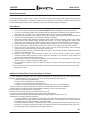
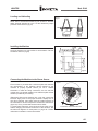
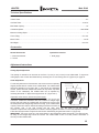
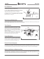
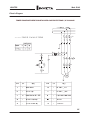
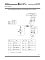
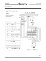
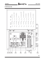
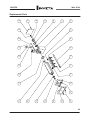
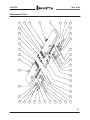
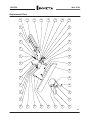
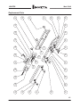
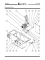
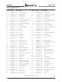
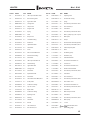
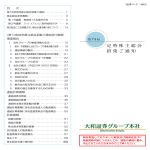
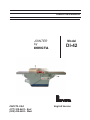
OPERATORS MANUAL
JOINTER
by
INVICTA
INVICTA USA
(877) 308-6423 - East
(800) 499-4682 - West
Model
DI-42
English Version
JOINTER
Model DI-42
General Instructions
As with all equipment, safety is to be a priority. The operator should understand the safety features and apply good
safety habits in transportation, adjustment, maintenance and operation of the machine. Practice and teach others
the safe operating procedures of this machine and help to prevent the possibility of accidents.
Safety Rules
1. For your own safety, read carefully the Instruction Manual before attempting to operate the machine.
2. If you are not thoroughly familiar and comfortable with the adjustment and operation of the machine, ask for
instruction from your supervisor or a fully qualified person. You may also contact Invicta USA.
3. Before the initial operation of the machine, remove all packaging, shipping grease and fully assemble the
machine. Pay special attention to the assembly of safety components.
4. Wear proper apparel while operating the machine. Never wear loose fitting clothing, gloves or ties. Always
remove rings or other jewelry before operating the machine. It is strongly suggested the operator wear
shoes with non-slip soles and also wear a protective hair net to prevent hair entanglement in moving parts.
5. Always wear personal safety equipment. Follow the safety regulations of your country and your company.
6. Have a certified person make all wiring connections to power source and properly ground the machine.
7. Always disconnect the machine from the power source and use lockout procedures before servicing,
changing cutting tools and during any cleaning of the machine.
8. Before starting the machine, be aware that the work area is clean and free of debris. Cluttered areas are
invitations for accidents to occur. .
9. Keep the safety guard(s) of the machine in place and in proper working condition. Never operate
machinery without safety equipment in place. Report any damage to your supervisor. Keep children and
visitors a safe distance from the working area.
10. Never leave the machine running while unattended. Turn off the power source during breaks. The machine
should come to a complete stop before walking away.
11. Do not operate the machine under the influence of drugs or alcohol. Consult your physician when taking
medications.
12. Do not force the machine beyond its limitations. It will produce a nicer and safer job and at the rate it was
designed to operate.
Additional Safety Rules for the Operation of Jointers
1) Avoid Kickbacks. “Kickback” can occur when the workpiece is forced back by the cutter during improper
operation. When “Kickback” occurs an injury can result. Some of the causes of Kickback are:
A- Dull and Improperly Adjusted Knives.
B- Knots, Nails or Imperfections in the workpiece.
C- Heavier Cuts than the machine was designed for.
D- Failure to use a pusher block when jointing or planing short, thin or narrow workpieces.
2) Always maintain the proper relationship of in-feed and out-feed table surfaces to the cutterhead.
3) Never start the work-piece into the cutterhead before allowing it to reach operation speed.
4) Keep the Knives sharp and free of rust and pitch
5) Never perform jointing or planing cuts deeper than l/8” (3 mm).
6) Support and control the workpiece properly all times during the operation.
7) Never reverse the direction of the workpiece after beginning operation. Kickback can occur.
8) Definitions of jointing and planing operations:
A- Jointing operations: The workpiece is positioned on the jointer with the narrow edge of work piece on the
in-feed table and the larger surface positioned against the fence. The workpiece is moved right to left from
the in-feed table across the cutterhead to the out-feed table.
B- Planing operations: Planing is a similar operation to the jointing operation except for the position of the
work piece. For planing, the larger flat surface of workpiece is placed on the infeed table of the jointer and
the narrow edge of the workpiece positioned against the fence.
01
JOINTER
Loading and Unloading
Mod. DI-42
Fig.01
Never load or unload the machine by the In-feed or Out-feed
tables because damage can occur. Lift the machine by straps
placed in areas shown in (Fig.01)
Installing the Machine
Level the machine on a solid surface to avoid vibration. See the
foundation sketch in (Fig.02)
Fig.02
Connecting the Machine to the Power Source
Fig.03
Each machine is provided with a reference plate that indicates
the requirements of the electrical service needed for the
machine to properly operate. Before you call a certified
electrician to make the wiring connections, be sure that the
voltage and cycle (phase) stated on this reference plate are the
same as provided in your building.
(Electrician) Remove the electrical box cover and connect the
electrical supply wires to the proper terminals. Rapidly turn on
and off the machine, then visibly check the rotation direction of
the cutterhead. It should correspond to the direction indicated on
(figure 03.) If not, proceed with the instructions below:
For three-phase machines: invert two wires of the power source
without changing the internal connections of the machine. See
the electrical diagrams for three-phase on page 06 if further
information is needed or contact Invicta USA.
CUTTERHEAD ROTATION DIRECTION
02
JOINTER
Mod. DI-42
Technical Specifications
In-feed Table……………………………………………………………………..………………..……………………….….57”
Out-feed Table……………………………………………………………………………………..……….…………...43 5/16”
Max Width Capacity...………………………………………………………………………………………..…………....….16”
Cutterhead Speed………………………………………………………………………………………………..…..5000 RPM
Maximum Cutting Depth………………………………………………………………………………………..…………...…1”
Fence Tilting.....................................................................................................................................................0º to 45º
Motor Power………………………………………………………………………………………………………….……7.5 HP
Net Weight………………………………………………………………………………………………………………1334 Lbs
Accessories
Normal Accessories
Optional Accessories
1. Instructions Manual
2. Tool Kit
1. Knife gauge
Adjustment Instructions
Cutting Depth Adjustment
The quantity of material to be removed can be from 0” (0 mm) to 3/4” (19 mm) on the infeed table. To adjust the
cutting depth, raise or lower the infeed table by loosening lock “G” and moving lever “E” (figure 06) on page 04.
Cutter Adjustment
For the best perfomance of the machine, the knives must be completely
aligned parallel with the surface of the outfeed table. The outfeed table
should be adjusted no more than 3/64” (1 mm) above the cutterhead
surface. (Never allow the outfeed table surface to drop below Top Dead
Center of the cutterhead) The outfeed table can be adjusted by
loosening the handle “F” (M) and moving the lever “D”. (Figure 6 & 7)
STRAIGHT EDGE
A
Adjustment of the Knives: (disconnect power supply)
Hold a straight edge firm against the outfeed table and across the
cutterhead. Rotate the cutterhead with knife installed. If straight edge
touches the knife raise the outfeed table and repeat the process until
Fig.04
the knife passes the straight edge without touching. (Lock outfeed table
in place) Check each side of cutterhead starting at the fence and then at
the operator side. If one side touches and the other does not, the knife is not yet parallel.
Continue to adjust knife until perfection is achieved. Securely tighten all screws “A” once final adjustment is made.
Follow the same procedure to adjust the other knives remembering to tighten the screws “A” (Figure 04)
IMPORTANT: The knives must be in the same relation to the straight edge when each knife is Top Dead Center.
No lifting of the straight edge should be noticed. The outfeed table is also in its best position. Remember to
securely lock the outfeed table.
03
JOINTER
Mod. DI-42
Fence Adjustment
The fence can be adjusted in two different ways:
l- For the angular adjustment loosen lock handle “B” and “C”.
Move the adjustment handle while referencing scale “D” for the
degree of tilt required. Re-lock “B” and “C”. See Fig.05
2) Adjust the cross movement of the fence in relation to the tables
by loosening lock “E” and sliding the fence to the desired
position. Re-lock “E”. See Fig. 05
Fig.05
Belts Tension and Replacement
Remove the belt guard to access the belt. Loosen locking nuts “F” & “G” and lift motor to remove belt or press down on the
motor to obtain an adequate tension. Re-Lock nuts “F” & “G". See Fig. 06
Table Alignment
This procedure is performed in the factory. If further
alignment is required due to damage, proceed as follows:
Loosen screw “H” and turn the adjustment bushing “I”
with a screwdriver until obtaining the desired alignment
between the table and the cutterhead body. Re-Lock
screw “H”. See Fig. “H”
Caution: For proper performance, the in-feed and outfeed tables must be parallel with the Cutterhead body.
Never align tables by referencing from the blades.
Cutters Maintenance
Keep the cutter knives as sets with the same weight and
dimensions. Knives used together with different weights
will cause imbalance. Sharpen periodically with a fine
grain stone and oil, maintaining a cutting angle of 40º.
Fig.06
Electrical Protection Equipment
The machine can be optionally supplied with electrical overload protection. This equipment breaks the supply current to the
motor automatically when there is an electrical overload that could cause damage. When overload has occurred, it is necessary
to reset the thermal relay by pressing the reset button prior activating the start button. See page 07 for electrical diagrams.
Machine Identification and Replacement Parts
Every machine has a manufacturing code (tag) which provides the manufacturer serial number and production date. This
manual gives listings of parts that form your machine. They provide description and order numbers. When needed, use original
parts; always mention the manufacturing code, part number and quantity desired.
04
JOINTER
Mod. DI-42
Electric Diagram
THWEE-PHASE MOTORIZATION WITH OVERLOAD PROTECTIONS-7,5CV 230/460V
05
JOINTER
Mod. DI-42
Electric Diagram
MONO-PHASE MOTORIZATION WITH OVERLOAD PROTECTIONS - 5CV 230/460V
06
JOINTER
Mod. DI-42
Electric Diagram
IMPORTANT
SELECT THE VOLTAGE (230/460V) OF YOUR
INTERNAL ELECTRIC NETWORK.
THE VOLTAGE SELECTION KEY IS LOCATED ON
THE ELECTRICAL BOX.
FOR YOU SAFETY THE VOLTAGE SELECTION
KEY IS ON NEUTRAL POSITION.
07
A1
96 NC
2 T1
A2
2-
98 NO
4 T2
3 L2
6 T3
5 L3
97 NO
3-
4NO
3NO
A2
95 NC
A2
4-
5
6
26
21
22
17
18
13
14
9
10
5
6
1
2
08
1-
1 L1
A1
25
07
06
05
04
03
02
01
7
8
9
1
2
3
4
09
11-02-0049-0
10
10
11-03-0009-0
11-03-0015-0
8
9
11-04-0075-0
11-31-0007-0
7
6
Press cable PG13.5
Borne terminal
1
Press cable PG21
Switch electrical
Single phase transformer
1
2
1
1
Overload relay RW27D
2
11-20-0008-0
5
Track
8NAE-K205-0
4
1
11-07-0069-0
3
Contactor CWM25
Disjuntor C6A 5SX1-1
1
11-34-0012-0
2
1
Electrical box
NAME
1
QTY.
11-28-0023-0
PART. N°
1
ITEM
JOINTER
Mod. DI-42
ELECTRICAL BOX
08
07
08
09
10
11
12
13
14
15
16
17
06
22
18
23
05
24
19
25
04
26
20
27
03
28
21
18
02
01
JOINTER
Mod. DI-42
Replacement Parts
09
34
36
88
32
29
34
32
44
31
43
29
42
41
38
39
32
32
30
31
42
31
34
41
37
35
39
34
29
33
32
31
29
88
45
40
39
32
38
39
31
30
29
JOINTER
Mod. DI-42
Replacement Parts
10
72
53
54
55
56
57
58
59
60
61
62
63
64
65
66
73
52
74
67
75
51
76
68
77
50
78
69
79
49
80
70
81
48
82
71
83
47
46
JOINTER
Mod. DI-42
Replacement Parts
11
107
87
103
102
101
100
99
87
87
89
87
86
85
90
91
108
109
92
110
93
111
94
87
86
85
95
96
97
87
104
86
105
98
106
85
84
JOINTER
Mod. DI-42
Replacement Parts
12
JOINTER
Mod. DI-42
Replacement Parts
112
138
139
137
136
135
134
133
132
113
131
130
114
115
129
116
128
117
127
118
126
119
120
121
122
123
124
125
124
13
JOINTER
Mod. DI-42
REPLACEMENT PARTS
FIG. Nº
CODE
QTY.
NAME
FIG. Nº
CODE
QTY. NAME
01..........
8NCV-K310-0
01......
Cutterhead shaft key
35……...
81DE-KK66-0
01…..
Table extension
02..........
81DE-KK30-0
01…...
Cutterhead shaft
36……...
06-03-0067-0
02…..
Allen cap screw M8x1.25x90
03..........
03-00-0033-0
01…...
Bearing 6206 2RS
37……...
81DE-KK40-0
01…..
Upper table shaft
04..........
06-18-0012-0
01…...
Snap ring E.30
38……...
81DE-K145-0
02…..
Table support
05……...
06-03-0097-0
04…...
Hex head cap screw 10x1,5x30
39……...
06-03-0067-0
16…..
Allen cap screw M8x1.25x90
06……...
81DE-KK11-0
01…...
Front bearing cover
40……...
81DE-KKK3-0
01…..
In-feed table
07……...
06-06-0035-0
02…...
Flat head screw M8x1.25x50
41……...
81DE-K111-0
02…..
Table end caps
08……...
06-13-0023-0
04…...
Flat washer
42……...
06-03-0071-0
10…..
Allen cap screw M6x1x20
09……...
81DE-KK10-0
01…...
Front bearing casting
43……...
06-04-0115-0
03…..
Hex head cap screw M8x1,25x16
10……...
8NFC-KK27-0
03…...
Knives
44……...
81DE-KK52-0
01…..
Upper chip duct
11……...
8NPF-KK20-0
12…...
Gibb screw
45……...
81DE-KKK2-0
01…..
Out-feed table
12……...
06-01-0008-0
04…...
Screw
46……...
06-04-0096-0
01…..
Hex head cap screw M6x1x25
13……...
81DE-KK54-0
01…...
Chip deflector
47……...
06-09-0019-0
03…..
Hex nut M6x1
14……...
8NCV-KK20-0
03…...
Knife gibb
48……...
81DE-K113-0
01…..
Fence support casting
15……...
8NMO-KK550
06…...
Knife spring
49………
27-00-0007-0
01…..
Knob
16……...
81DE-KK12-0
01…...
Rear bearing casting
50……...
8NPW-K545-0 01…..
Fence adjusting lever
17……...
03-00-0077-0
01…...
Bearing 6208 2RS
*51…...
06-03-0085-0
01…..
Allen cap screw M10x1, 5x90
*52…….
81DE-KK37-0
01…..
Guard support
19……… 8NPM-KK93-0 01…… Driven pulley
*53……
81DE-KK67-0
01…..
Cutter safety guard
20……… 84DS-K100-0
01…… Cutterhead shaft washer
*54……
81DE-KK36-0
01…..
Spring
21……… 06-05-0039-0
02…… Round head screw M6x1x10
*55……
81DE-KK38-0
01…..
Support bushing for guard
22……… 81DE-KK50-0
01…… Rear bearing cover
*56……
06-02-0060-0
01…..
Allen setscrew M8x1.25x16
23……… 06-04-0099-0
01…… Hex head cap screw 12x1.75x30
*57……
06-02-0043-0
01…..
Allen setscrew M6x1x16
24……… 81DE-K115-0
01…… Lower fence slide
58………
81DE-K114-0
01…..
Fence
25……… 26-05-0002-0
01…… Roll pin
59………
81DE-K117-0
01…..
Mounting shaft
26……… 81DE-K124-0
01…… Fixation guide
60………
06-03-0061-0
02…..
Allen cap screw M8x1.25x30
27……… 81DE-K125-0
01…… Mounting pin for fixation guide
61………
81DE-K129-0
01…..
Locking block
28……… 06-03-0061-0
02…… Allen cap screw M8x1.25x30
62………
81DE-K119-0
01…..
Locking collar
29……… 06-03-0068-0
08…… Allen cap screw M10x1.5x50
63………
81DE-K136-0
01…..
Fence adjustment scale
30……… 81DE-KK46-0
02…… Table adjusting lever
64………
06-13-0019-0
02…..
Flat washer
31……… 81DE-KK43-0
08…… Fixation plate
65………
06-05-0053-0
02…..
Round head screw M4x0,7x10
32……… 81DE-KKK9-0
04…… Knob
66………
06-05-0062-0
02…..
Round head screw M4x0,7x16
33……… 8NVL-K362-0
01…… Upper table shaft
67……..
81DE-K122-0
01…..
Scale pointer
34……...
04…… Lower table shaft
68……..
81DE-K123-0
01…..
Support
18……… 06-18-0026-0
81DE-KK41-0
02…… Bearing retainer clip I.80
* 81DE-K011-0 Cutter Head Guard Assembly
14
JOINTER
Mod. DI-42
FIG. Nº CODE
QTY. NAME
FIG. Nº
CODE
QTY. NAME
69……..
06-03-0061-0
02…..
Allen cap screw M8x1.25x30
105……
81DE-KK48-0
01…..
Adjusting screw
70……..
81DE-K118-0
01…..
Rear mounting shaft
106……
81DE-KKK7-0
01…..
Out-feed rear casting
71……..
81DE-K112-0
01…..
Upper fence slide
107……
07-01-0007-0
02…..
Spring
72……..
8NMN-KK79-0
01…..
Locking Knob
108……
06-04-0121-0
02…..
Hex head cap screw M10x1.5x30
73……..
26-00-0002-0
01…..
Roll pin 3x24
109……
06-09-0021-0
02…..
Hex nut M10x1,5
74……..
81DE-K121-0
01…..
Plunger shaft
110……
06-13-0026-0
08…..
Flat washer
75……..
07-00-0026-0
01…..
Spring
111……
06-04-0121-0
08…..
Hex head cap screw M10x1.5x30
76……..
8NMN-KK58-0
01…..
Knob
112……
29-34-0030-0
01…..
Motor (specify cap.)7,5cv –2polos
77……..
26-00-0006-0
01…..
Roll pin 3x16
113……
81DE-KK19-0
01…..
Motor plate
78……..
81DE-K120-0
01…..
Threaded bushing
114……
81DE-KK71-0
08…..
Roll pin
79……..
26-00-0002-0
01…..
Shaft 3x24
115……
81DE-K131-0
01…..
Dust extraction manifold (optional)
80……..
27-00-0013-0
01…..
Adjustable Handle
116……
06-04-0115-0
02…..
Hex head cap screw M8x1,25x16
81……..
06-13-0015-0
01…..
Flat washer
117……
81DE-KK64-0
01…..
Internal chip duct plate
82……..
81DE-K127-0
01…..
Collar
118……
81DE-KKK1-0
01…..
Base
83……..
06-02-0070-0
02…..
Allen set screw M6x1x25
119……
11-27-0001-0
01…..
ON Button (green)
84……..
81DE-KKK6-0
01…..
Out-feed front casting
120……
11-27-0012-0
01…..
Off Button (red)
85……..
06-13-0013-0
08…..
Flat washer
121……
10-03-0128-0
01…..
Switch/Name Plate
86……..
06-03-0069-0
08…..
Allen cap screw M6x1x16
122……
06-05-0039-0
06…..
Round head screw M6x1x10
87……..
81DE-KK15-0
08…..
Lateral bushing
123……
11-33-0003-0
01…..
Junction box
88……..
8NVL-K361-0
02…..
Upper table shaft
124……
06-05-0039-0
06…..
Round head screw M6x1x10
89……..
8NMN-KK56-0
01…..
Locking knob
125……
11-02-0048-0
01…..
Electrical Terminal Block
90……..
06-13-0026-0
02…..
Flat washer
126……
06-04-0122-0
02…..
Hex head cap screw M10x1,5x60
91……..
8NCA-KK34-0
01…..
Adjustable handle
127……
06-13-0026-0
02…..
Flat washer
92……..
06-13-0019-0
02…..
Flat washer
128……
06-09-0021-0
01…..
Hex nut M10x1,5
93……..
06-05-0043-0
02…..
Round head screw M5x0,8x10
129……
06-04-0069-0
01…..
Hex head cap screw M10x1,5x80
94……..
10-04-0011-0
01…..
Scale pointer
130……
8NVZ-KKK8-0
01…..
Rear vented cover
95……..
81DE-KKK4-0
01…..
In-feed front casting
131……
06-05-0039-0
06…..
Round head screw M6x1x10
96……..
06-17-0003-0
02…..
Pop AD. 3,2x15
132……
06-04-0121-0
01…..
Hex head cap screw M10x1,5x30
97……..
10-00-0016-0
01…..
Depth Scale
133……
8NAR-K113-0
01…..
Flat washer
98……..
81DE-KKK5-0
01…..
In-feed rear casting
134……
81DE-KK49-0
01…..
Motor base pívot shaft
99……..
81DE-KK47-0
01…..
Adjusting screw
135……
06-13-0026-0
04…..
Flat washer
100……
8NAN-K315-0
01…..
Bushing
136……
06-04-0098-0
04…..
Hex head cap screw M10x1,5x35
101……
06-13-0026-0
01…..
Flat washer
137……
8NPM-KK40-0
01…..
Motor pulley
102……
27-00-0018-0
01…..
Handle
138…….
15-00-0030-0
02…..
“V” belt
103……
06-09-0021-0
01…..
Hex nut M10x1,5
139…….
06-02-0054-0
104……
06-09-0022-0
01…..
Hex nut M12x1,75
01….. Allen setscrew M8x1,25x10
OTHER ITEMS
01…. Knife setting gauge
81DE-2011-0
15
Parts and Service
[email protected]
[email protected]
www.invicta-usa.com