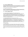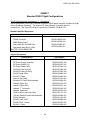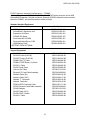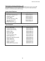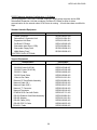
1
NSTS 21000-IDD-760XD Shuttle/Payload Interface Definition Document for the Payload and General Support Computer (PGSC) Space Shuttle Vehicle Engineering Office Baseline July 1999 NASA National Aeronautics and Space Administration Lyndon B. Johnson Space Center Houston, Texas 77058 NSTS 21000-IDD-760XD Shuttle/Payload Interface Definition Document for the Payload and General Support Computer July 1999 Baseline Approved by Original Signed By: B. J. Watkins Co-Chairman, Portable Onboard Computer Control Board Original Signed By: N. A. Woodbury Co-Chairman, Portable Onboard Computer Control Board NATIONAL AERONAUTICS AND SPACE ADMINISTRATION LYNDON B. JOHNSON SPACE CENTER HOUSTON, TEXAS 77058 NSTS 21000-IDD-760XD NOTICE--WHEN ANY GOVERNMENT DRAWINGS, SPECIFICATIONS, OR OTHER DATA ARE USED FOR ANY PURPOSE OTHER THAN IN CONNECTION WITH A DEFINITELY RELATED GOVERNMENT PROCUREMENT OPERATION, THE UNITED STATES GOVERNMENT THEREBY INCURS NO RESPONSIBILITY NOR ANY OBLIGATION WHATSOEVER: AND THE FACT THAT THE GOVERNMENT MAY HAVE FORMULATED, FURNISHED, OR IN ANY WAY SUPPLIED THE SAID DRAWINGS, SPECIFICATION, OR OTHER DATA IS NOT TO BE REGARDED BY IMPLICATION OR OTHERWISE AS IN ANY MANNER LICENSING THE HOLDER OR ANY OTHER PERSON OR CORPORATION, OR CONVEYING ANY RIGHTS OR PERMISSION TO MANUFACTURE, USE, OR SELL ANY PATENTED INVENTION THAT MAY IN ANY WAY BE RELATED THERETO. 1 NSTS 21000-IDD-760XD INTRODUCTION The Payload and General Support Computer (PGSC) is a service used to support Shuttle and Payload on-orbit operations. The primary functions are command and display of non-critical payloads and additional crew information services. The number of PGSC’s manifested is determined on a flight-by-flight basis. The Space Shuttle Portable Onboard Computer Control Board determines flight-by-flight configurations. Sufficient PGSC’s are always flown to satisfy the requirements of all users and to provide adequate backup capability. In addition, the PGSC hardware is a Space Shuttle controlled resource. The “flight-like” PGSC system with power supply and communications cabling may be obtained on loan for two weeks. It has the same configuration as the regular flight PGSC and may be used by the user/experimenter for final verification of software/hardware operation and interfacing. The Portable Onboard Computer Control Board will control changes to this document. 2 NSTS 21000-IDD-760XD TABLE OF CONTENTS 1.0 1.1 1.2 1.3 1.4 1.5 SCOPE..................................................................................................................................................... 6 PURPOSE ................................................................................................................................................. 6 GENERAL................................................................................................................................................ 6 CONFIGURATION CONTROL................................................................................................................ 6 LOGISTICS .............................................................................................................................................. 6 CONTACTS ............................................................................................................................................. 6 2.0 APPLICABLE DOCUMENTS ............................................................................................................... 8 3.0 OVERVIEW .......................................................................................................................................... 10 3.1 PGSC/THINKPAD 760XD UNMODIFIED INTERFACES ........................................................................ 18 3.1.1 RS-232 Serial I/O Port .................................................................................................................... 18 3.1.2 Parallel Port ................................................................................................................................... 18 3.1.3 Keyboard/Mouse Connector............................................................................................................ 18 3.1.4 External Display Connector............................................................................................................ 18 3.1.5 Personal Computer Memory Card Internal Association (PCMCIA) slots......................................... 18 3.1.6 Headphone Jack.............................................................................................................................. 18 3.1.7 Microphone/Line-in Jack ................................................................................................................ 19 3.1.8 External Bus Connector .................................................................................................................. 19 3.1.9 Video In .......................................................................................................................................... 19 3.1.10 Video Out ................................................................................................................................... 19 3.1.11 External Diskette Drive Connector ............................................................................................. 19 3.1.12 Joystick/MIDI ............................................................................................................................. 19 3.2 EXPANSION UNIT CONFIGURATION ................................................................................................ 19 3.3 EXPANDED/EXTENDED MEMORY.................................................................................................... 20 3.4 ROM BIOS (READ ONLY MEMORY BASIC INPUT/OUTPUT SERVICES) ....................................... 20 3.4.1 BIOS Settings.................................................................................................................................. 20 3.4.2 BIOS Settings Confirmation ............................................................................................................ 22 4.0 4.1 4.2 4.3 4.4 4.5 4.6 4.7 4.8 5.0 MECHANICAL..................................................................................................................................... 25 PHYSICAL OUTLINE............................................................................................................................ 25 THERMAL ............................................................................................................................................. 25 VELCRO LOCATIONS AND OUTSIDE DIMENSIONS....................................................................... 25 MOUNTING CONSIDERATIONS ......................................................................................................... 27 OPERATING PRESSURE RANGE......................................................................................................... 27 HUMIDITY............................................................................................................................................. 27 WEIGHT................................................................................................................................................. 27 ELECTROMAGNETIC COMPATIBILITY (EMC) CONSIDERATIONS .............................................. 27 POWER REQUIREMENTS................................................................................................................. 29 5.1 ELECTRICAL POWER CHARACTERISTICS....................................................................................... 29 5.1.1 DC Power ....................................................................................................................................... 29 5.1.2 AC Power........................................................................................................................................ 29 5.2 CURRENT CHARACTERISTICS FOR POWER ON.......................................................................... 29 5.2.1 Current for PGSC laptop computer with expansion unit .................................................................. 29 5.2.2 Current for PGSC laptop computer only ......................................................................................... 30 5.3 EXTERNAL POWER SUPPLY .............................................................................................................. 31 5.4 PAYLOAD-SUPPLIED POWER............................................................................................................. 31 6.0 PGSC-FLIGHT LAPTOP CONFIGURATION OVERVIEW ............................................................ 32 6.1 PGSC FLIGHT LAPTOP IRQ TABLE ........................................................................................................... 32 6.2 PGSC FLIGHT LAPTOP I/O ADDRESS TABLE.............................................................................................. 33 6.3 PGSC FLIGHT LAPTOP DMA CHANNEL TABLE ......................................................................................... 33 3 NSTS 21000-IDD-760XD 6.4 PGSC FLIGHT LAPTOP MEMORY ADDRESS ALLOCATIONS ......................................................................... 33 6.5 CONFIGURATION #1.................................................................................................................................. 34 6.5.1 Configuration #1 - Standalone with Dual Port RS-422 PC-Card (PCMCIA Card)........................... 34 6.5.2 Configuration #1 - Standalone with RS-422 Usage Table ................................................................ 34 6.6 CONFIGURATION #2.................................................................................................................................. 35 6.6.1 Configuration #2 - SelectaDock I with PC-Decom (AT-Bus) Card and Dual Port RS-422 PC-Card (PCMCIA Card) .......................................................................................................................................... 35 6.6.2 Configuration #2 - PC-Decom and RS-422 Usage Table ................................................................. 35 6.7 CONFIGURATION #3.................................................................................................................................. 35 6.7.1 Configuration #3 - SelectaDock I with OCA (AT-Bus) Card ............................................................ 35 6.7.2 Configuration #3 - OCA Usage Table ............................................................................................. 36 6.8 CONFIGURATION #4.................................................................................................................................. 36 6.8.1 Configuration #4 - SelectaDock I with Proshare (AT-Bus) Card and Dual Port RS-422 PC-Card (PCMCIA Card) .......................................................................................................................................... 36 6.8.2 Configuration #4 - Proshare and RS-422 Usage Table.................................................................... 37 6.9 CONFIGURATION #5.................................................................................................................................. 37 6.9.1 Configuration #5 - SelectaDock I with Dual Port RS-422 Sealevel AT-Bus Card............................. 37 6.9.2 Configuration #5 - SelectaDock I with Dual Port RS-422 Sealevel Usage Table ............................. 38 6.10 RS-232C COMMUNICATIONS ......................................................................................................... 39 6.10.1 RS-232C Line Drivers/Receivers................................................................................................. 39 6.11 RS-422A COMMUNICATIONS ......................................................................................................... 39 6.11.1 Quatech PCMCIA RS-422/485 Dual Channel Serial Adapter Card............................................. 39 6.11.2 Sealevel ISA RS-422A Serial I/O ISO Communication Card........................................................ 39 6.11.3 RS-422 Adapter .......................................................................................................................... 39 6.12 ETHERNET COMMUNICATIONS .............................................................................................................. 40 6.12.1 3Com Etherlink III LAN PC Card ............................................................................................... 40 6.13 VIDEO COMMUNICATIONS..................................................................................................................... 40 7.0 INTERFACE CABLES ......................................................................................................................... 41 7.1 POWER CABLES................................................................................................................................... 41 7.1.1 PGSC 28V DC Power Cable (25 feet).............................................................................................. 41 7.1.2 PGSC 28V DC Power Cable (6 feet)................................................................................................ 42 7.1.3 16-20V DC Power Supply Cable (25 feet)........................................................................................ 42 7.1.4 AC Power W-Cables........................................................................................................................ 43 7.2 COMMUNICATION CABLES ............................................................................................................... 45 7.2.1 RS-232C Cables.............................................................................................................................. 45 7.2.2 RS-422A Cables .............................................................................................................................. 48 8.0 MISCELLANEOUS .............................................................................................................................. 52 8.1 APPROVED FLOPPY DISKS................................................................................................................. 52 8.2 APPROVED WRITABLE CDS ............................................................................................................... 52 8.3 CD GENERATION PROCEDURES ....................................................................................................... 52 APPENDIX A - ACRONYMS AND ABBREVIATIONS ................................................................................ 53 ANNEX 1............................................................................................................................................................ 56 PGSC Flight Computer Configuration 1 - Standalone ................................................................................ 56 PGSC Expansion Assembly Configuration 2 - PCMMU.............................................................................. 57 PGSC Expansion Assembly Configuration 3 - OCA ..................................................................................... 58 PGSC Expansion Assembly Configuration 4 - ProShare .............................................................................. 59 PGSC Expansion Assembly Configuration 5 - RS-422 ................................................................................. 60 4 NSTS 21000-IDD-760XD INDEX OF TABLES TABLE 3-I. - THINKPAD 760XD/PGSC COMPARISON ....................................................................... 17 TABLE 4-I. PGSC COMPONENT WEIGHTS ....................................................................... 28 TABLE 5-I. DC POWER TEST RESULTS ....................................................................... 29 TABLE 5-2 AC POWER TEST RESULTS* ....................................................................... 29 TABLE 7-I. RECOMMENDED CONNECTOR MATES FOR THE RS-232C CABLES............................. 45 INDEX OF FIGURES FIGURE 3-1 PGSC FLIGHT LAPTOP (ISO VIEW) ....................................................................... 11 FIGURE 3-2 PGSC FLIGHT LAPTOP (LEFT SIDE) ....................................................................... 12 FIGURE 3-3 PGSC FLIGHT LAPTOP (RIGHT SIDE) ....................................................................... 12 FIGURE 3-4 PGSC FLIGHT LAPTOP (REAR VIEW) ....................................................................... 13 FIGURE 3-5 PGSC FLIGHT LAPTOP WITH EXPANSION UNIT (ISO VIEW) ....................................... 13 FIGURE 3-6 PGSC FLIGHT LAPTOP WITH EXPANSION UNIT (REAR VIEW) (NO CARD TRAY)...... 14 FIGURE 3-7 PGSC AND EXPANSION UNIT WITH CARD TRAY (LEFT SIDE) .................................... 14 FIGURE 3-8 PGSC AND EXPANSION UNIT WITH CARD TRAY AND ................................................. 15 TYPICAL PCMCIA CARD INSTALLED (RIGHT SIDE) FIGURE 3-9 PGSC FLIGHT LAPTOP DC POWER INTERFACE DIAGRAM......................................... 15 FIGURE 3-10 PGSC FLIGHT LAPTOP WITH EXPANSION UNIT AC POWER INTERFACE DIAGRAM16 FIGURE 4-1 PGSC FLIGHT LAPTOP BOTTOM VELCRO PLACEMENT (INFORMATION ONLY) .... 26 FIGURE 4-2 PGSC EXPANSION UNIT BOTTOM VELCRO PLACEMENT (INFORMATION ONLY).. 26 FIGURE 5-1 POWER ON AC CURRENT REQUIREMENT .................................................................. 30 FIGURE 5-2 POWER ON DC CURRENT REQUIREMENT .................................................................. 30 FIGURE 5.3 EXTERNAL 2.6 AMP DC POWER SUPPLY.......................................................................... FIGURE 6-1 WIRING DIAGRAM, RS-422 ADAPTER ....................................................................... 40 FIGURE 7-1. 28V DC POWER CABLE (25 FEET) ....................................................................... 41 FIGURE 7-2. 28V DC POWER CABLE (6 FEET) ....................................................................... 42 FIGURE 7-3 16-20V DC POWER CABLE (25 FEET) ....................................................................... 42 FIGURE 7-4 AC POWER W-CABLE - SED46117063 ....................................................................... 43 FIGURE 7-5 AC POWER W-CABLE - SED46117140-301.................................................................... 44 FIGURE 7-6 AC POWER W-CABLE EXTENSIONS- SED4611714-302 THROUGH -305 .................... 45 FIGURE 7-7 DB9F TO DB25M RS-232C CABLE SCHEMATIC............................................................ 46 FIGURE 7-8 DB9F TO DB9M RS-232C CABLE SCHEMATIC.............................................................. 47 FIGURE 7-9 COMPUTER INTERFACE PANEL ....................................................................... 48 FIGURE 7-10 PAYLOAD DATA INTERFACE PANEL ....................................................................... 48 FIGURE 7-11 RS-422/CHANNEL 1 CABLE SCHEMATIC .................................................................... 49 FIGURE 7-12 RS422Y/CABLE SCHEMATIC ....................................................................... 50 FIGURE 7-13 SED39126962 - PDIP RS-422 Y CABLE ....................................................................... 51 5 31 NSTS 21000-IDD-760XD 1.0 SCOPE 1.1 PURPOSE The purpose of this document is to: a. Define and control the interfaces provided by the PGSC and associated components for use by payloads and crew software, and b. Define and control constraints observed by payload and crew support users. 1.2 GENERAL This document defines all interfaces available to the PGSC assembly and identifies configurations for the government furnished equipment (GFE) communications and power cables supplied with the PGSC assembly. In this document, the term “PGSC Flight Laptop” refers to the flight ThinkPad 760XD computer as modified: whereas, the term “ThinkPad 760XD” refers to the commercial IBM ThinkPad 760XD sold by the manufacturer. In the text, the terms “shall,” “will,” and “must” are used when compliance is mandatory. “May” or “should” indicate a choice exists. 1.3 CONFIGURATION CONTROL The Space Shuttle Program Portable Onboard Computer Control Board will maintain configuration control of this document in accordance with the Shuttle/Payload Configuration Management Plan for the Payload and General Support Computer (PGSC), JSC 27891. 1.4 LOGISTICS The payload integration plan (PIP) will clearly define the role of the PGSC for each specific payload. The SSP is responsible for maintaining flight-ready PGSC systems for operation as authorized by the PIP. Section 3 provides an overview of the various PGSC hardware items. Standard Flight PGSC configurations are provided in Annex 1. If you have questions about PGSC logistics, please contact one of the Portable Onboard Computer Control Board CoChairmen, B. Watkins at (281) 244-1335 or N. Woodbury at (281) 244-5790. 1.5 CONTACTS NASA/Johnson Space Center, mail code MV2 Avionics and Software Office Bobby Watkins, (281) 244-1335, Portable Onboard Computer Co-Chairman NASA/Johnson Space Center, mail code EA5 Biomedical Hardware Development Office David Stephenson, (281) 483-5859 6 NSTS 21000-IDD-760XD NASA/Johnson Space Center, mail code DL4 Portable Onboard Computing and Tools Neil Woodbury, (281) 244-5790, Portable Onboard Computer Co-Chairman NASA/Johnson Space Center, mail code DO5 Payload Operations Branch Project Engineer for applicable payload NASA/Johnson Space Center, mail code DL42 Mission Operations Procedures Branch POC Coordinator for applicable flight 7 NSTS 21000-IDD-760XD 2.0 APPLICABLE DOCUMENTS The following documents form a part of this document to the extent specified herein. In the event of conflict between the documents referenced and the contents of this document, the contents of this document shall be considered a superseding requirement. U.S. Government Documents FED STD 1020A Telecommunications Electrical Characteristics of Balanced Voltage Digital Interface Circuits NSTS 1700.7B Safety Policy and Requirements for Payloads Using the Space Transportation System, January 1989 NASA documents NSTS 07700, Volume XIV NSTS 21000-IDD-MDK JSC 27891 JSC 28015 JSC 28060 JSC 17038 JSC 27394 Space Shuttle System Payload Accommodations (and 10 appendixes) Shuttle/Payload Interface Definition Document for Middeck Accommodations Shuttle/Payload Configuration Management Plan for the Payload and General Support Computer (PGSC) Payload and General Support Computer (PGSC) Discrepancy Reporting Procedures Portable Onboard Computer Software Management Plan SSP Flight Equipment Non-Critical Hardware Program Requirements Document Orbiter Communications Adapter (OCA) End Item Specification Document Industry documents ThinkPad ThinkPad 760XD/760XL/765D/765L User’s Guide, July 1997 International Business Machines Corporation Armonk, NY. EIA STD RS232C Electronic Industries Association (EIA) Recommended Standards (RS) 232C: Interface between data terminal equipment and data circuit-terminating equipment employing serial binary data interchange. EIA STD RS422A Electronic Industries Association (EIA) Recommended Standards (RS) 422A: Electrical characteristics of balanced voltage digital 8 NSTS 21000-IDD-760XD interface circuits. Industry documents (continued) IBM Select-a-Dock User’s Guide, July 1997 International Business Machines Corporation Armonk, NY. INTEL ProShare™ Personal Conferencing Video System User’s Guide ProShare Video System 150 Intel Corporation, 1995 QUATECH DSP-200/300 User’s manual Dual Channel RS-422/485 PCMCIA Asynchronous Adapter Quatech Incorporated, 1996 SEALEVEL ACB-530 Part #4111 users manual Sealevel Systems Incorporated, 1994 IS0-COMM part no. 3417 users manual Sealevel Systems Incorporated, 1992 WIGSD Windows Interface Guidelines for Software Design Microsoft Corporation, 1995 3Com 3Com Etherlink III User’s Manual 3C589D-COMBO 3Com Incorporated, 1996 9 NSTS 21000-IDD-760XD 3.0 OVERVIEW The PGSC computer assembly is a ThinkPad 760XD model laptop computer that is IBM ATBus/PCI compatible, and has been modified for use in the Orbiter environment. The PGSC computer assembly and the following hardware items are GFE and are available for use on Space Shuttle missions. This list only represents commonly used GFE items. (Note: Contact B. Watkins at (281) 244-1335 or N. Woodbury at (281) 244-5790 for current GFE hardware items and for current versions of software). a) PGSC Flight Laptop (IBM ThinkPad 760XD) b) removable floppy drive c) external floppy drive case d) removable hard drive (3.0 GB) e) removable CD-ROM drive (8X) f) NiMH battery pack g) expansion unit (SelectaDock I) h) power supply power cable i) 28V DC power supply assembly j) PCMMU cable (24 ft.) k) RS-422 Y cable (15 ft.) l) RS-422 cable (25 ft.) m) RS-422 Quatech Card/Cable Assembly n) RS-422 Adapter o) Video in/out cable assembly p) DC power cable (25 ft.) q) DC power cable (6 ft.) r) AC W power cable s) RS-232 quad cable t) RS-232C cable (25-9 pin) u) RS-232A cable (9-9 pin) v) RS-232 Y cable w) PDIP RS-422 Y cable x) OCA Ku-Band/Audio Cable y) PCMCIA Ethernet card with cable z) PGSC Flight Laptop expansion assembly (PCMMU board) aa) PGSC Flight Laptop expansion assembly (OCA board) bb) PGSC Flight Laptop expansion assembly (Proshare board) cc) PGSC Flight Laptop expansion assembly (RS-422 ISO Com PC board) 10 NSTS 21000-IDD-760XD The figures in this section represent various views of the PGSC Flight Laptop and the Expansion Unit assemblies. Figures 3-1 through 3-8 depict the standard connectors found on the ThinkPad 760XD and Expansion Unit assemblies as described in paragraph 3.1 and 3.2, respectively. Figures 3-9 and 3-10 depict the DC and AC power interface diagrams. Table 3-I is a summary comparison of the ThinkPad 760XD and the PGSC Flight Laptop assembly. Most information required by PGSC users can be found in the IBM ThinkPad 760XD/760XL/765D/765L User’s Guide, dated July 1997 listed in Section 2.0 Applicable Documents. FIGURE 3-1 PGSC FLIGHT LAPTOP (ISO VIEW) 11 NSTS 21000-IDD-760XD FIGURE 3-2 PGSC FLIGHT LAPTOP (LEFT SIDE) FIGURE 3-3 PGSC FLIGHT LAPTOP (RIGHT SIDE) 12 NSTS 21000-IDD-760XD FIGURE 3-4 PGSC FLIGHT LAPTOP (REAR VIEW) 120V AC/DC Power Input Connector FIGURE 3-5 PGSC FLIGHT LAPTOP WITH EXPANSION UNIT 13 NSTS 21000-IDD-760XD FIGURE 3-6 PGSC FLIGHT LAPTOP WITH EXPANSION UNIT (REAR VIEW) (NO CARD TRAY) FIGURE 3-7 PGSC AND EXPANSION UNIT WITH CARD TRAY (LEFT SIDE) 14 NSTS 21000-IDD-760XD PCMCIA Slots Strain Relief FIGURE 3-8 PGSC AND EXPANSION UNIT WITH CARD TRAY AND TYPICAL PCMCIA CARD INSTALLED (RIGHT SIDE) J1 DC POWER CABLE PGSC-760XD COMPUTER WITHOUT EXPANSION CHASSIS J2 POWER ADAPTER CABLE DC POWER CONVERTER FIGURE 3-9 PGSC FLIGHT LAPTOP DC POWER INTERFACE DIAGRAM 15 NSTS 21000-IDD-760XD PGSC-760XD COMPUTER WITH EXPANSION CHASSIS AC W POWER CABLE FIGURE 3-10 PGSC FLIGHT LAPTOP WITH EXPANSION UNIT AC POWER INTERFACE DIAGRAM 16 NSTS 21000-IDD-760XD TABLE 3-I. - ThinkPad 760XD/PGSC Comparison 32-bit 166 MHz Pentium MMX CPU Floating Point Unit (FPU) System memory (DRAM standard/optional) 2 Mb VRAM for display subsystem 512 kb BIOS Flash ROM XGA Color screen 1024 x 768 x 65536 pixel resolution Bit-mapped graphic display capability External XGA compatible monitor connector 84 keys of standard IBM AT External keyboard/mouse/keypad connector One 3.5 in., 1.44 Mb internal floppy disk drive (removable) External floppy drive connector One removable hard disk drive One parallel printer port One 28.8 baud modem (COM2) One RS-232C port (COM1) Two isolated RS-422A ports (COM2, COM4) 240-pin PCI/ISA Expansion Bus 28-Vdc isolated external power supply Isolated internal dc power supply Internal cooling fan Internal dc power supply voltage PCMCIA Connector L1 Cache L2 Cache CMOS EEPROM Audio Infrared ThinkPad 760XD yes yes 32/104 Meg yes yes yes yes yes yes yes yes yes PGSC Flight Laptop Yes Yes 64 Meg Yes Yes Yes Yes Yes Yes Yes Yes Yes yes up to 5.7 GB yes yes yes no yes no yes yes 20V yes 32 KB 256 KB 128 Bytes 1 KB Mwave 2780 500 KHz Yes 3.0 GB Yes No* Yes PCMCIA card Yes Yes* Yes Yes 20V Yes 32 KB 256 KB 128 Bytes 1 KB Mwave 2780 Disabled * Modifications to the ThinkPad 760XD for the PGSC 17 NSTS 21000-IDD-760XD 3.1 PGSC/ThinkPad 760XD UNMODIFIED INTERFACES The PGSC Flight Laptop assembly is equipped with twelve IBM standard interfaces as supplied by the original manufacturer, IBM Corporation. The ThinkPad 760XD 28.8-baud modem was removed for the flight configuration to accommodate power modifications. The interfaces are: • • • • • • • • • • • • RS-232 serial input/output (I/O) port Parallel connector (Centronics) Keyboard/Mouse connector External display connector PCMCIA slots (accepts two Type I or Type II PC cards, or one Type III PC card) Headphone jack Microphone/Line-in jack (supports a dynamic microphone or a self-battery-powered condenser microphone) External Bus Connector Video In Video Out External Diskette Drive Connector Joystick/MIDI For more detailed information regarding these connectors, see the IBM ThinkPad 760XD/XL, 760E/ED/EL User’s Guide. 3.1.1 RS-232 Serial I/O Port The IBM ThinkPad 760XD provides an IBM AT compatible RS-232 serial I/O port. For more information about this port, see section 7. 3.1.2 Parallel Port The parallel port is functionally equivalent to the IBM AT printer adapter. The port supports Centronics-type (parallel) printers general-purpose parallel I/O port. The interface is provided through a 25-pin, D-shell, female connector located on the rear panel. 3.1.3 Keyboard/Mouse Connector This is the port where you connect an external mouse, external keyboard, or external numeric keypad. 3.1.4 External Display Connector This is the port where you connect the external display. 3.1.5 Personal Computer Memory Card Internal Association (PCMCIA) slots Accepts two Type I or two Type II PCMCIA cards, or one Type III PCMCIA Card. The PCMCIA slots provide an interface to the computer for data storage, memory, network interface, etc. 3.1.6 Headphone Jack A 1/8-inch (3.5-mm) diameter jack where a stereo headphone or external speakers connect. 18 NSTS 21000-IDD-760XD 3.1.7 Microphone/Line-in Jack A 1/8-inch (3.5-mm) diameter jack where a stereo microphone or external audio device is connected. 3.1.8 External Bus Connector This is the port used to connect the expansion assembly. 3.1.9 Video In From the video in port you can capture still images or motion video and overlay motion video. 3.1.10 Video Out From the video out port you can export motion video. 3.1.11 External Diskette Drive Connector Attach an external diskette drive here to allow both the CD-ROM drive and the diskette drive to be used simultaneously. 3.1.12 Joystick/MIDI A joystick can be attached here as well as musical instruments with MIDI ports. 3.2 EXPANSION UNIT CONFIGURATION Details of the standard PGSC Flight Laptop Configurations are provided in Annex 1. Configuration 1 (PGSC Flight Laptop without Expansion Unit) is listed in this section only to provide completeness for standard configurations. The PGSC with Expansion Assembly (Configuration 2, 3, 4, & 5) contains the interfaces listed in section 3.1 plus the combinations of the following: Configuration 1 • Stand alone PGSC Flight Laptop without expansion assembly. Configuration 2 • PCMMU port - The Pulse Code Modulation Master Unit (PCMMU) is the Orbiter central processing unit that includes all of the Orbiter downlink (OD) telemetry. Select PCMMU data may be de-commutated by the PGSC PC-DECOM software and routed via packetized data to other PGSC’s. Configuration 3 • OCA port - The OCA includes two functionally independent sections: the Ku-band • interface and the modem interface. The OCA system, consisting of a single printed circuit board, associated software, and interface cable, provides a means for two-way transfer of computer files between a ground-based computer and a Payload and General Support Computer (PGSC) on-board the Orbiter. Configuration 4 • Proshare (AT-Bus) Card - The Proshare (AT-Bus) Card provides a means for two-way transfer of video teleconferencing sessions between a ground-based computer and a Payload and General Support Computer (PGSC) on-board the Orbiter. 19 NSTS 21000-IDD-760XD Configuration 5 • 2, 9-pin Serial RS-422 port- Refer to Sealevel users manual for details. For more detailed information regarding these connectors, see IBM ThinkPad 760XD/XL, 760E/ED/EL User’s Guide, IBM Expansion Unit documentation, Sealevel documentation, Quatech documentation, and OCA documentation. The current expansion assembly configurations 2, 3, 4, and 5 consist of a one-slot expansion unit that supports standard computer cards. When a standard ISA/PCI card is installed, an optional card cage cover is mounted on the rear of the expansion assembly for protection. The typical power usage of the expansion assembly with card(s) is approximately 35 watts. 3.3 EXPANDED/EXTENDED MEMORY The standard configuration of the PGSC assembly contains 64MB of random access memory (RAM). The PGSC Flight Laptop uses Microsoft Windows 95 system software. This operating systems software was designed to alleviate base memory restrictions and does not require special memory management software used on previous versions of the PGSC. Previously used MS-DOS programs can still be run on the PGSC Flight Laptop using the DOS 7 software provided by Windows 95. For more information regarding extended or expanded memory management on the PGSC, see ThinkPad 760XD/XL, 760 E/ED/EL User’s Guide. 3.4 ROM BIOS (READ ONLY MEMORY BASIC INPUT/OUTPUT SERVICES) The current ROM BIOS in the PGSC is version 2.02, dated 3-12-98. Upgrades to the BIOS may occur in the future. If application software is dependent upon a certain BIOS version, the BIOS version number is stored in address F000:FFF5 in the PGSC memory in American Standard Code for Information Interchange (ASCII) format. 3.4.1 BIOS Settings The BIOS settings for the ThinkPad 760XD are as follows: Power Management Hibernation File - Enabled AC Hibernation Timer = 0 (Disabled) AC Standby Timer = 0 (Disabled) AC Suspend Power Timer = 0 (Disable) AC LCD Off Timer = 0 (Disable) AC Hard Disk Off Timer = 0 (Disable) AC Processor Speed = Maximum AC Power Mode = Custom DC Hibernation Timer = 0 (Disabled) DC Standby Timer = 0 (Disabled) DC Suspend Power Timer = 0 (Disable) DC LCD Off Timer = 59 Minutes DC Hard Disk Off Timer = 20 Minutes 20 NSTS 21000-IDD-760XD DC Processor Speed = Maximum DC Power Mode = Custom Enter Suspend When Lid is Closed = Disabled Timer set for Suspend Function = Enabled On Low Battery Suspend the Computer = Enabled RediSafe Suspend Mode = Disabled Use Switch for On/Off (Not Hibernation) = Enabled Hibernation from Suspend Timer = Disabled Expansion Unit Suspend = Disabled LCD Battery Brightness = Normal Video Presentation Mode = Enabled Screen = LCD and External Horizontal and Vertical Expansion = Enabled Use <Fn><F8> Key Combination to Toggle Expansion = Enabled Enhanced Video = Shares Interrupt of PCI Bus - See Miscellaneous Section Audio Digital Signal Processor (DSP) = Enabled DSP IRQ = 5 DSP Address = 4E30 DSP DMA = 7 DSP MIDI Function = Disabled DSP Soundblaster Emulation = Disabled DSP Internal Modem = Disabled Warning Beeps = Enabled Wakeup on Ring Indicator = Disabled LCD Panel Speaker Indicator = Enabled Infrared Port Infrared (IR) Data Transmissions = Disabled IR Ports = Front and Back IR Mode = ThinkPad Format IR COM Address = 03E8 IR IRQ = 4 IR Infrared Address = 01A0 IR DMA 3 = Enabled Infrared Power = Off Internal RS-232D Port Serial Port Power = On Serial Port Use = Enabled Serial Port Address = COM1 Parallel Port 21 NSTS 21000-IDD-760XD Parallel Port = Enabled Parallel Port Address = LPT1 Parallel Port Type = Bidirectional Disk Drives Floppy Disk Drive = Enabled as External Secondary Hard Disk Drive = Enabled (IRQ 15) Keyboard <Fn> Key Locked-Down = Disabled Keyboard Type Rate = Normal TrackPoint III = Enabled Miscellaneous PCI IRQ = 11 Joystick Port = Enabled PC CardBus 1 = Disabled PC CardBus 2 = Disabled Display Startup Screen = Enabled 3.4.2 BIOS Settings Confirmation The AutoXD utility is a series of batch and executable files that automatically configure an IBM ThinkPad 760ED and 760XD computer. The program is designed to be autonomous and requires very little user inputs. When completed with the AUTOXD function, the following checklist can be used to verify that the BIOS settings have been properly configured. The following checklist assumes use of Windows 95 Utility diskette (UTTPFW95) version 4.10 or later for the ThinkPad 760ED/760XD. All items should already be set to their shown value with AUTOXD except as noted. The following should be checked within “ThinkPad Configuration”. 1 - System Information A - BIOS Part Number = B - Machine Type = SKZ39131208 for 760ED SKZ39131209 for 760XD 9546U3A for 760ED 9546U9E for 760XD 2 - TrackPoint A - TrackPoint - Enabled B - Mouse Properties Button - Right-Handed C - Mouse Properties Pointer Trail = Disabled D - Mouse Properties General = Standard PS/2 Port Mouse 22 NSTS 21000-IDD-760XD 3 - Audio A - Audio - Enabled B - Sound Properties - Check Sound Assignments C - Audio - Playback/Recording = Mwave Wave Audio Driver D - CD Music - CD-ROM drive = D: E - CD Music - Headphones = High 4 - Infrared A - Infrared - Disabled 5 - Accessibility Options A - Fn key lock - Disabled B - Speaker Indicator - Enabled 6 - MIDI/Joystick A - MIDI port - Disabled B - Joystick - Enabled 7 - Docking Station (Not Used for PCS/SSC) 8 - External Display (Settings depend upon software load) A - Display Properties Settings 800x600 (760ED) 1024x768 (760XD) B - Display Properties Pallet 24-bit (760ED) 64K (760XD) 9 - Parallel Port A - Parallel Port - Enabled B - Operating Mode - Bidirectional 10 - LCD A - Screen Blanking - Disabled B - Screen Expansion - Enabled C - Screen Brightness - Normal 11 - Enhanced Video / MPEG (Default values) A - Video-Out : Disabled (Indicates that Video-In is Enabled) C - Color Standard - NTSC D - Underscan - Enabled E - Flicker Free - On 12 - Internal Modem A - Internal Modem - Disabled 13 - Serial Port A - Serial Port - Enabled 14 - PC-Card A - Red Bar Next to Icon B - Enabled CardBus - Disabled 15 - Ultrabay 23 NSTS 21000-IDD-760XD A - Secondary IDE Device - Enabled 16 - Power Management A - Power Properties Power - Advanced B - Power Properties Power Mode AC - Customized C - Power Properties Power Mode AC Timers - All 0’s D - Power Properties Processor AC - Maximum E - Power Properties Power Mode DC - Customized F - Power Properties Power Mode DC Timers - Suspend 0, Screen 59, HDD 20 G - Power Properties Processor DC - Maximum 17 - Status Bar A - Customized B - LCD+External Display 24 NSTS 21000-IDD-760XD 4.0 MECHANICAL 4.1 PHYSICAL OUTLINE The PGSC Flight Laptop has almost the same footprints as the commercial IBM ThinkPad 760XD. Its dimensions are 2.0 inches high, 11.7 inches wide, and 8.3 inches in depth with display folded down in the stowed position. For the PGSC with expansion assembly the dimensions are 3.5 inches high, 15.5 inches wide, and 16.5 inches in depth. 4.2 THERMAL One fan is located in the rear of the Expansion Unit Assembly for cooling. There is also a fan mounted internally on the Video card within the IBM ThinkPad 760XD computer with a small outlet vent on the rear of the computer. The fan within the computer is not visible or accessible to the user. The fans in the expansion chassis and computer allow for cooler operation in the microgravity environment. However, testing performed on the computer indicated a 7 degree Fahrenheit exceedance of the 113-degree F allowable touch temperature limit. A waiver for this requirement was applied for and granted (ref. G05149). Do not block the vent or fan during operation of the units. 4.3 Velcro LOCATIONS AND OUTSIDE DIMENSIONS The structural interface with habitable modules (Space Shuttle Orbiter, SpaceHab, etc.) is with Velcro. Refer to drawing SDZ39129262, Computer Assembly, Payload and General Support Computer (PGSC) and SEZ39131224, Expansion Unit Assembly, for details of Velcro placement, connectors, and markings. See Figure 4-1 and Figure 4-2 for illustration of Velcro placement. 25 10.5 .75 NSTS 21000-IDD-760XD FRONT EDGE 5.5 .8 1.1 0 5.0 8.65 0 0 7.3 .7 FIGURE 4-1 PGSC FLIGHT LAPTOP BOTTOM VELCRO PLACEMENT (INFORMATION ONLY) .4 FRONT EDGE 0 10.5 FIGURE 4-2 PGSC EXPANSION UNIT BOTTOM VELCRO PLACEMENT (INFORMATION ONLY) 26 NSTS 21000-IDD-760XD 4.4 MOUNTING CONSIDERATIONS Velcro strips are attached to the PGSC to aid in mounting the unit securely in a microgravity environment. When securing the unit, the following should be observed: a) b) c) d) e) f) 4.5 Do not block the air vent located on the units Do not block access to the CD-ROM Do not block access to side or rear connectors Do not block access to the PCMCIA slots Do not block access to the PGSC power switch Place the unit in an area that allows the screen to be appropriately opened. OPERATING PRESSURE RANGE The PGSC operates at orbiter cabin pressures ranging from 14.7 to 10.2 psi. 4.6 HUMIDITY The PGSC can operate in normal orbiter cabin humidity. 4.7 WEIGHT A partial list of PGSC assembly component weights is shown in Table 4-I. 4.8 ELECTROMAGNETIC COMPATIBILITY (EMC) CONSIDERATIONS The PGSC is certified via the Space Shuttle Program Flight Equipment Non-Critical Hardware Program Requirements Document, JSC-17038, for on Orbit operations. EMC results for standard PGSC configurations can be made available by contacting the Portable Onboard Computer Control Board Co-Chairman, B. Watkins at (281) 244-1335 or N. Woodbury at (281) 244-5790. All non-standard PGSC configurations will have to undergo proper EMC testing. 27 NSTS 21000-IDD-760XD TABLE 4-I. - PGSC COMPONENT WEIGHTS PGSC 760XD Computer Removable hard drive 3GB Removable 8X CD-ROM Removable floppy drive External floppy drive case Floppy drive bezel SelectaDock I Expansion Unit with base and card cover Expansion Unit Base PCMCIA 260MB Hard Drive PCMMU PC board RS-422 Iso Com PC board RS-422 PC (Quatech) card/cable assembly 422 Adapter AC “W” Cable (15 ft) (SED46117063) AC “W” Cable (1.5 ft) (SED46117140) AC “W” Cable (5 ft extension) (to be used with SED46117140) AC “W” Cable (10 ft extension) (to be used with SED46117140) AC “W” Cable (15 ft extension) (to be used with SED46117140) AC “W” Cable (20 ft extension ) (to be used with SED46117140) DC power cable (25 ft) DC power cable (6 ft) DC power supply cable DC power supply PCMMU cable (24 ft) PCMMU port mode cable (1 ft) RS-422A Y cable (15 ft) RS-422 cable (24 ft) RS-232A cable (9-pin version) RS-232C cable (25-pin version) RS-232 Y cable Video in/out cable assembly ProShare PC Board Battery Pack NiMH RS 422 PDIP Y Cable RS 232 Quad Cable PCMCIA Ethernet card/Ethernet cable OCA Board OCA Cable (25 ft) 28 Weight (lb.) 5.01 0.49 0.8 0.51 0.51 0.01 6.85 3.15 0.2 0.35 0.5 0.23 0.25 1.4 .63 .36 .50 .64 .78 1.25 0.5 0.75 1.5 0.75 0.25 1.5 1.75 1.25 1.25 1.5 .09 0.6 1.15 2.1 2.4 0.25 0.88 2.0 NSTS 21000-IDD-760XD 5.0 POWER REQUIREMENTS 5.1 ELECTRICAL POWER CHARACTERISTICS 5.1.1 DC Power Electrical power characteristics were determined by high fidelity testing at the Electrical Power Systems Laboratory using a STS power bus to power a PGSC SED39126010-305 power supply that provided the necessary operating power to the PGSC. Current was measured for different input voltages, and readings were taken at the power source while the PGSC was running a program that caused approximately 75-80% of the screen pixels to be turned on and while the removable Ni-MH battery was charging. Results of the test are shown in Table 5-I. TABLE 5-I. - DC POWER TEST RESULTS Input voltage (Vdc) Current (amps) Power (watts) For PGSC only - dc power 24.0 28.0 32.0 1.63 1.40 1.24 39.2 39.2 39.7 5.1.2 AC Power AC Electrical power characteristics were determined by connecting an AC power supply to the PGSC Expansion Chassis Assembly. Current was measured for different input voltages, and readings were taken while the PGSC was running a program that caused approximately 7580% of the screen pixels to be turned on. Results of the test are shown in Table 5-2. TABLE 5-2 AC POWER TEST RESULTS* Input voltage (Vac) Current (mAac) Power (watts) For PGSC with Expansion Assembly* using 117 Vac @ 400Hz 117.0 782.2 58 *Typical Expansion Assembly, Configurations 2, 3, 4, and 5. Results may vary with configuration. 5.2 CURRENT CHARACTERISTICS FOR POWER ON 5.2.1 Current for PGSC laptop computer with expansion unit 29 NSTS 21000-IDD-760XD FIGURE 5-1 POWER ON AC CURRENT REQUIREMENT 5.2.2 Current for PGSC laptop computer only FIGURE 5-2 POWER ON DC CURRENT REQUIREMENT 30 NSTS 21000-IDD-760XD 5.3 EXTERNAL POWER SUPPLY An external DC to DC power supply is required for the PGSC computer without Expansion Assembly configuration. Figure 5-3 below shows a sketch of an external power supply. FIGURE 5.3 EXTERNAL 2.6 AMP DC POWER SUPPLY 5.4 PAYLOAD-SUPPLIED POWER Power may be provided to the PGSC through a middeck payload. The unique payload to the PGSC DC interface cable must be equivalent to the PGSC DC power cable (SED331033334). When using the PGSC with an Expansion Tray, a PGSC AC power cable (SED46117140 or SED46117063), or equivalent, should be used. 31 NSTS 21000-IDD-760XD 6.0 PGSC-Flight Laptop Configuration Overview Five configurations have been defined for the PGSC Flight Laptop (all configurations can use the 3Com Ethernet PCMCIA card): • Standalone with RS-422 PCMCIA Card • Docked with PC-Decom AT-Bus and RS-422 PCMCIA Cards • Docked with OCA AT-Bus Card (Ku and PADM) • Docked with Proshare AT-Bus and RS-422 PCMCIA Cards • Docked with RS-422 Sealevel AT-Bus Card All Serial Devices use either IRQ4 or IRQ3. Standard I/O Address Are Used for COM1 through COM4. Note: Sealevel Dual Port RS-422 card also uses IRQ10 for second port (set to COM4). The Mwave Audio Device Uses IRQ5 in all configurations. The PCMCIA Network Adapter Uses IRQ9 for all configurations. All AT-Bus Cards Use IRQ10. The SelectaDock I can only house a single AT-Bus card in each configuration. Note: Sealevel Dual Port RS-422 card also uses IRQ3 for the first port. All PCI-Related items, including SCSI, use IRQ11. Primary IDE uses IRQ14 and Secondary IDE uses IRQ15 in all configurations. IRQ3 and IRQ9 can be used by removing either the RS-422 PCMCIA card or the Ethernet PCMCIA card, respectively. The RS-422 PCMCIA card and OCA/PADM cannot be installed on the same PGSC system due to interrupt and I/O address conflicts. 6.1 PGSC Flight Laptop IRQ Table The following table lists the interrupt allocations for all configurations. The IRQs are arranged numerically: IRQ 0 System timer IRQ 1 Keyboard IRQ 2 Cascade to IRQ9 IRQ 3 OCA (PADM) or Quatech Dual Port RS-422 (COM2 and COM4) or Sealevel RS422 Port #1 (COM2) IRQ 4 Built-In RS-232 (COM1) IRQ 5 MWave Audio IRQ 6 Floppy Diskette Controller IRQ 7 Parallel Port IRQ 8 Real Time Clock IRQ 9 3Com Ethernet IRQ 10PC-Decom, OCA (Ku), or Proshare or Sealevel RS-422 Port #2 (COM4) IRQ 11PCI (Including SelectaDock I SCSI) IRQ 12Trackpoint III IRQ 13Math Coprocessor IRQ 14HDD / CD-ROM (Primary IDE) IRQ 15Secondary IDE 32 NSTS 21000-IDD-760XD 6.2 PGSC Flight Laptop I/O Address Table The following table lists the I/O Address allocations for all configurations. The addresses are arranged numerically (devices which use non-contiguous address will appear multiple times): Timer Keyboard Mouse RTC Secondary IDE HDD/CD OCA/PADM Proshare PC-Decom Proshare OCA/Ku COM4(422) COM2(422) 3Com Ethernet Secondary IDE Video LPT1(Prt) Video PCMCIA PCMCIA Dock COM3 FDD CD COM1(232) Video Video Video Mwave Video SD-I SCSI II 6.3 0040-0043 0060, 0064 0060, 0064 0070-0071 0170-0177 01F0-01F7 0200-0221 0224-0227 0238-023F 0240-024F 02E0-02E7 02E8-02EF 02F8-02FF 0300-030F 0376-0377 03B4-03B5, 03BA 03BC-03BE 03C0-03CF, 03D4-03D5, 03D8-03DA 03E0-03E1 03E2-03E3 03E8-03EF 03F0-03F7 03F6-03F7 03F8-03FF 2100-21FF 43C6-43C9 46E8 4E30-4E3F 83C6-83C9 Set By System Only PGSC Flight Laptop DMA Channel Table The following table lists the DMA Channel allocations for all configurations. The addresses are arranged numerically: DMA Channels: 0 Unused 1 PC-Decom 2 FDD 3 PC-Decom 4 Unused 5 Unused 6 Unused 7 Mwave 6.4 PGSC Flight Laptop Memory Address Allocations 33 NSTS 21000-IDD-760XD The following table lists the memory addresses that should be excluded for DOS applications when using an upper memory manager (such as EMM386). In addition to the address shows, memory used by a PCMCIA adapter card should also be excluded. This restriction does not apply to Windows 95 users. Memory Addresses: A0000-BFFFF Video C0000-C7FFF Video 6.5 Configuration #1 6.5.1 Configuration #1 - Standalone with Dual Port RS-422 PC-Card (PCMCIA Card) Com Port Description Internal RS-232D PC-Card #1 RS-422 #1 PC-Card #1 RS-422 #2 PC-Card #2 3Com Ethernet Available 6.5.2 COM Number COM1 IRQ Number IRQ4 I/O Address Locations 03F8-03FF DMA Channel N/A COM2 IRQ3 02F8-02FF N/A COM4 IRQ3 02E8-02EF N/A N/A IRQ9 0300-030F N/A 16550 UART Equivalent 16550 UART Equivalent 16550 UART Equivalent PC-Card N/A IRQ10 N/A N/A N/A Configuration #1 - Standalone with RS-422 Usage Table Interrupt Number IRQ0 IRQ1 IRQ2 IRQ3 Device I/O Address Timer Keyboard Cascade Int RS-422 Ports 1 and 2 IRQ4 IRQ5 IRQ6 IRQ7 IRQ8 IRQ9 IRQ10 IRQ11 IRQ12 RS-232 on ThinkPad Mwave Audio Floppy Drive Controller Parallel Port Real Time Clock Ethernet PC-Card Unused PCI Bus TrackPoint III Pointing Device Math Coprocessor Primary IDE Secondary IDE 0040-0043 0060, 0064 N/A 02F8-02FF 02E8-02EF 03F8-03FF 4E30-4E3F 03F0-03F7 0140-015F 0070-0071 0300-030F N/A N/A 0060, 0064 IRQ13 IRQ14 IRQ15 N/A 01F0-01F7 0170-0177 34 DMA Channel N/A N/A N/A N/A N/A 7 2 N/A N/A N/A N/A N/A N/A N/A N/A N/A Controller NSTS 21000-IDD-760XD 6.6 Configuration #2 6.6.1 Configuration #2 - SelectaDock I with PC-Decom (AT-Bus) Card and Dual Port RS-422 PC-Card (PCMCIA Card) Com Port Description Internal RS-232D PC-Card #1 RS-422 #1 PC-Card #1 RS-422 #2 PC-Decom AT-Bus SCSI-II Adapter PC-Card #2 3Com Ethernet 6.6.2 COM Number COM1 IRQ Number IRQ4 I/O Address Locations 03F8-03FF DMA Channel N/A COM2 IRQ3 02F8-02FF N/A COM4 IRQ3 02E8-02EF N/A SCC1A and SCC1B N/A IRQ10 0238-023F 1 and 3 IRQ11 (PCI) N/A N/A IRQ9 Set By System 0300-030F Configuration #2 - PC-Decom and RS-422 Usage Table Interrupt Number IRQ0 IRQ1 IRQ2 IRQ3 Device I/O Address Timer Keyboard Cascade Int RS-422 Ports 1 and 2 IRQ4 IRQ5 IRQ6 IRQ7 IRQ8 IRQ9 IRQ10 IRQ11 RS-232 on ThinkPad Mwave Audio Floppy Drive Controller Parallel Port Real Time Clock Ethernet PC-Card PC-Decom PCI Bus / SCSI-II IRQ12 TrackPoint III Pointing Device Math Coprocessor Primary IDE Secondary IDE 0040-0043 0060, 0064 N/A 02F8-02FF 02E8-02EF 03F8-03FF 4E30-4E3F 03F0-03F7 0140-015F 0070-0071 0300-030F 0238-023F Set by System 0060, 0064 IRQ13 IRQ14 IRQ15 N/A N/A 01F0-01F7 0170-0177 DMA Channel N/A N/A N/A N/A N/A 7 2 N/A N/A N/A 1 and 3 N/A N/A N/A N/A N/A 6.7 Configuration #3 6.7.1 Configuration #3 - SelectaDock I with OCA (AT-Bus) Card 35 Controller 16550 UART Equivalent 16550 UART Equivalent 16550 UART Equivalent Zilog 8530 Internal to SelectaDock I PC-Card NSTS 21000-IDD-760XD Com Port Description Internal RS-232D OCA/PADM AT-Bus OCA/KuBand AT-Bus SCSI-II Adapter PC-Card #1 3Com Ethernet 6.7.2 COM Number COM1 IRQ Number IRQ4 I/O Address Locations 03F8-03FF DMA Channel N/A COM2 IRQ3 N/A N/A IRQ10 02F8-02FF 0200-0221 02E0-02E7 16550 UART Equivalent Unique N/A Unique N/A IRQ11 (PCI) IRQ9 Selected by System 0300-030F N/A Internal to SelectaDock I PC-Card N/A Configuration #3 - OCA Usage Table Interrupt Number IRQ0 IRQ1 IRQ2 IRQ3 Device I/O Address Timer Keyboard Cascade Int OCA/PADM IRQ4 IRQ5 IRQ6 IRQ7 IRQ8 IRQ9 IRQ10 IRQ11 RS-232 on ThinkPad Mwave Audio Floppy Drive Controller Parallel Port Real Time Clock Ethernet PC-Card OCA/Ku Band PCI Bus / SCSI-II IRQ12 TrackPoint III Pointing Device Math Coprocessor Primary IDE Secondary IDE 0040-0043 0060, 0064 N/A 0200-0221 02F8-02FF 03F8-03FF 4E30-4E3F 03F0-03F7 0140-015F 0070-0071 0300-030F 02E0-02E7 Set By System 0060, 0064 IRQ13 IRQ14 IRQ15 6.8 N/A Controller N/A 01F0-01F7 0170-0177 DMA Channel N/A N/A N/A N/A N/A 7 2 N/A N/A N/A N/A N/A N/A N/A N/A N/A Configuration #4 6.8.1 Configuration #4 - SelectaDock I with Proshare (AT-Bus) Card and Dual Port RS-422 PC-Card (PCMCIA Card) Com Port Description COM Number IRQ Number I/O Address Locations 36 DMA Channel Controller NSTS 21000-IDD-760XD Internal RS-232D PC-Card #1 RS-422 #1 PC-Card #1 RS-422 #2 Proshare AT-Bus SCSI-II Adapter PC-Card #2 3Com Ethernet 6.8.2 COM1 IRQ4 03F8-03FF N/A COM2 IRQ3 02F8-02FF N/A COM4 IRQ3 02E8-02EF N/A N/A IRQ10 N/A N/A IRQ11 (PCI) N/A IRQ9 0224-0227 0240-024F Selected by System 0300-030F N/A N/A 16550 UART Equivalent 16550 UART Equivalent 16550 UART Equivalent Unique Internal to SelectaDock I PC-Card Configuration #4 - Proshare and RS-422 Usage Table Interrupt Number IRQ0 IRQ1 IRQ2 IRQ3 Device I/O Address Timer Keyboard Cascade Int RS-422 Ports 1 and 2 IRQ4 IRQ5 IRQ6 IRQ7 IRQ8 IRQ9 IRQ10 RS-232 on ThinkPad Mwave Audio Floppy Drive Controller Parallel Port Real Time Clock Ethernet PC-Card Proshare IRQ11 PCI Bus / SCSI-II IRQ12 TrackPoint III Pointing Device Math Coprocessor Primary IDE Secondary IDE 0040-0043 0060, 0064 N/A 02F8-02FF 02E8-02EF 03F8-03FF 4E30-4E3F 03F0-03F7 0140-015F 0070-0071 0300-030F 0224-0227 0240-024F Set By System 0060, 0064 IRQ13 IRQ14 IRQ15 N/A 01F0-01F7 0170-0177 DMA Channel N/A N/A N/A N/A N/A 7 2 N/A N/A N/A N/A N/A N/A N/A N/A N/A 6.9 Configuration #5 6.9.1 Configuration #5 - SelectaDock I with Dual Port RS-422 Sealevel AT-Bus Card Com Port Description Internal RS-232D COM Number COM1 IRQ Number IRQ4 I/O Address Locations 03F8-03FF 37 DMA Channel N/A Controller 16550 UART Equivalent NSTS 21000-IDD-760XD Sealevel ATBus RS-422 #1 Sealevel ATBus RS-422 #2 PC-Card #2 3Com Ethernet SCSI II Adapter 6.9.2 COM2 IRQ3 02F8-02FF N/A 16550 UART Equivalent COM4 IRQ10 02E8-02EF N/A 16550 UART Equivalent N/A IRQ9 0300-030F N/A PC-Card N/A IRQ11 (PCI) N/A N/A Internal to SelectaDock I Configuration #5 - SelectaDock I with Dual Port RS-422 Sealevel Usage Table Interrupt Number IRQ0 IRQ1 IRQ2 IRQ3 IRQ4 IRQ5 IRQ6 IRQ7 IRQ8 IRQ9 IRQ10 IRQ11 Device I/O Address Timer Keyboard Cascade Int RS-422 Port #1 (COM2) RS-232 on ThinkPad Mwave Audio Floppy Drive Controller Parallel Port Real Time Clock Ethernet PC-Card RS-422 Port #2 (COM4) PCI Bus / SCSI-II IRQ12 TrackPoint III Pointing Device Math Coprocessor Primary IDE Secondary IDE 0040-0043 0060, 0064 N/A 02F8-02FF 03F8-03FF 4E30-4E3F 03F0-03F7 0140-015F 0070-0071 0300-030F 02E8-02EF Set by System 0060, 0064 IRQ13 IRQ14 IRQ15 N/A 01F0-01F7 0170-0177 38 DMA Channel N/A N/A N/A N/A N/A 7 2 N/A N/A N/A N/A N/A N/A N/A N/A N/A NSTS 21000-IDD-760XD 6.10 RS-232C COMMUNICATIONS The PGSC contains one RS-232C asynchronous serial I/O port that provides a communication link between the PGSC and an external device. This is a standard serial port as defined in EIA STD RS232C. This port is a 9-pin version compatible with an IBM PC-AT 9-pin serial port. For RS-232C cable pin outs and description, see paragraph 7.2.1. 6.10.1 RS-232C Line Drivers/Receivers The PGSC uses standard bipolar line drivers/receivers, the 1489 transmitter and the 1488 receiver. The 1488 line driver is capable of producing 14.8 mA current. Information regarding the line drivers/receivers is readily available in published data manuals. 6.11 RS-422A COMMUNICATIONS 6.11.1 Quatech PCMCIA RS-422/485 Dual Channel Serial Adapter Card The Quatech PCMCIA RS-422/485 interface is a standard Commercial off the Shelf (COTS) PC Card 2.1 compliant Type II PCMCIA component which adds two fully independent asynchronous RS-422 interfaces to the PGSC Flight Computer. The card uses a 16550 UART with programmable baud rate and data formats. A maximum serial link of up to 4000 feet may be realized. The RS-422 maximum baud rate is 115.2K. Consult the Quatech DSP-200/300 User’s Manual for additional information. 6.11.2 Sealevel ISA RS-422A Serial I/O ISO Communication Card The Sealevel RS-422A Serial ISO Communication Card is a COTS “SEALEVEL” AT compatible PC board (part number 3417). The ISO-com board uses a 16550 UART with programmable baud rate and data formats. The board allows very long distance (5,000 ft. at 9,600 baud) communication with virtually error free differential drive characteristics. The ISOcom board provides the PGSC with two ground isolated serial ports. NOTE: Certain Expansion Unit configurations have one of the ports disabled. Consult the User’s Manual for additional information. 6.11.3 RS-422 Adapter The RS-422 Adapter is an in-house designed adapter allowing compatible communications between a Quatech PCMCIA RS-422/485 Dual Channel Serial Adapter Card (SDG39129284301) and other compatible RS-422 communication devices. The adapter applies a termination resistance of 100 Ohms across the Data input and Auxiliary input pins to help eliminate noise from the channel line and allows interface with existing RS-422 flight cables. See figure 6-1 for details 39 NSTS 21000-IDD-760XD FIGURE 6-1 WIRING DIAGRAM, RS-422 ADAPTER 6.12 Ethernet Communications 6.12.1 3Com Etherlink III LAN PC Card The 3Com Etherlink III LAN PC Card is a COTS standard Type II PCMCIA Ethernet communications card that is PC Card 2.1 compliant. The 3Com 3C589D-COMBO card is 10BASE-2 and 10BASE-T compatible. A combo cable is attached to the card which allows the use of either a coaxial cable connection via a BNC Connector or a Level 3 twisted pair connection via a RJ-45 Connector. Network segments up to 1000 ft can be attained with a coaxial cable (RG58 C/U) and segments up to 328 ft can be attained with Level 3 unshielded twisted pair. The maximum throughput is 10 Mbps. Consult the 3Com 3C589D-COMBO User’s Manual for additional information. 6.13 Video Communications The PGSC contains one video-in jack and one video-out jack. Either jack requires the use of an IBM COTS modified video interface cable assembly P/N SEZ39131213-301. The color standard is National Television Standards Committee (NTSC) or Phase-Alternation-by-Line (PAL) format. The standard is controlled through software settings. The video cable assembly provides two type of connection: S-Video Jack and Composite Video Jack. The information below describes the video specifications for each of the input/output jacks. S-Video Jack - 4-pin mini DIN jack - Y signal: 1Vpp 75 ohm with negative composite sync - C signal: 0.286Vpp 75 ohm Composite Video Jack - Pin jack - 1Vpp 75 ohm with negative composite sync 40 NSTS 21000-IDD-760XD 7.0 INTERFACE CABLES 7.1 POWER CABLES The PGSC Flight Laptop configurations use Space Shuttle 28-Vdc power supplied only through a PGSC DC power cable. If the PGSC is powered through the payload, then the proper connector mates are the following: dc Cable connector = MS3475L-8-33S dc Mating connector = MS3470L-8-33P 7.1.1 PGSC 28V DC Power Cable (25 feet) The dc power cable, part number SED33103334, connects the 28V DC Power Supply with the 28-Vdc Space Shuttle power or experiment dc power. For details see Figure 7-1. GRN/WHT DC FAULT GND A BLU/WHT DC POWER B WHT DC RETURN C (NC) ORN/WHT FIGURE 7-1. - 28V DC POWER CABLE (25 FEET) 41 L J K ORBITER 28 VDC POWER NSTS 21000-IDD-760XD 7.1.2 PGSC 28V DC Power Cable (6 feet) The dc power cable, part number SED39122875, connects the 28V DC Power Supply with the 28-Vdc Space Shuttle power or experiment dc power. For details, see Figure 7-2. FIGURE 7-2. - 28V DC POWER CABLE (6 FEET) 7.1.3 16-20V DC Power Supply Cable (25 feet) The dc power supply cable SED39126013 is required with the 28V DC power cable and 28V DC power supply to supply 16-20V DC Power to the PGSC computer configuration only. For details see Figure 7-3. B L U /W H T DC POWER B WHT DC POWER RTN C O R G /W H T CHASSIS GND A D E Part No. SED39126013 FIGURE 7-3 16-20V DC POWER ADAPTER CABLE (25 FEET) 42 A B C NSTS 21000-IDD-760XD 7.1.4 AC Power W-Cables AC W cable part numbers SED46117063-301 and SEG46117140-301 connect the PGSC Expansion Unit with the 115V AC 400Hz Space Shuttle power. Use of the SEG46117140-302 through -305 cables allows for customized cable lengths when used with the SEG46117140301 W cable. Either cable permits the connection of multiple expansion units (up to a maximum of 3) from a single AC power source. For details, see Figure 7-4, Figure 7-5, and Figure 7-6. -301 Wiring Diagram FIGURE 7-4 AC POWER W-CABLE - SED46117063 43 NSTS 21000-IDD-760XD FIGURE 7-5 AC POWER W-CABLE - SED46117140-301 44 NSTS 21000-IDD-760XD FIGURE 7-6 AC POWER W-CABLE EXTENSIONS- SED46117140-302 THROUGH -305 7.2 COMMUNICATION CABLES Communication with payloads is accomplished via cables provided for the RS-232C port (for cabin payloads), and the two RS-422A ports (for payload bay payloads). 7.2.1 RS-232C Cables Two 14-foot RS-232C cables are provided for experiments located in the orbiter cabin. The first cable, a DB9 (female) to DB25 (male) part number SED33103335, is fully compatible with an IBM AT serial cable. The second cable is a DB9 (female) to DB9 (male), part number SED33103348. Refer to Table 7-I for the proper connector mates. For details of each cable schematic, see Figures 7-7 and 7-8. RS-232 Y and Quad cables are also provided for PCMMU PGSC output to experiment PGSC connections. Table 7-I. - RECOMMENDED CONNECTOR MATES FOR THE RS-232C CABLES 25-pin (Figure 7-4) 9-pin (Figure 7-5) Cable end Experimenter/panel mate AMP206800-2 AMP206801-2 * AMP207252-2 AMP207253-2 * * or equivalent 45 Jack/Port ITT D110551 ITT D110551 NSTS 21000-IDD-760XD FIGURE 7-7 DB9F TO DB25M RS-232C CABLE SCHEMATIC. 46 NSTS 21000-IDD-760XD FIGURE 7-8 DB9F TO DB9M RS-232C CABLE SCHEMATIC. 47 NSTS 21000-IDD-760XD 7.2.2 RS-422A Cables One RS-422A cable provides a communication link between the PGSC and payload in the payload bay. This cable connects the PDIP or CIP to the PGSC. The PDIP/CIP connector has a part number of NLS6GT12-35P and is a male connector. The CIP and PDIP are shown in Figures 7-9 and 7-10. A DB9-S female connector mates with an RS-422 adapter to the PCMCIA RS-422 card/cable assembly. In addition, a DB9-S female connector mates with RS422A connector located on the Expansion Assembly of the PGSC (Configuration 5). A schematic of this cable is provided in Figure 7-11. The RS-422A Y cable is used to transfer information between two or three PGSC’s. A schematic is provided in Figure 7-12. The PDIP RS-422A Y cable provides a communication link between the payload and two PGSC configurations. A schematic is provided in Figure 7-13. FIGURE 7-9 COMPUTER INTERFACE PANEL (CIP) FIGURE 7-10 PAYLOAD DATA INTERFACE PANEL (PDIP) 48 NSTS 21000-IDD-760XD FIGURE 7-11 RS-422A/CHANNEL 1 CABLE SCHEMATIC 49 NSTS 21000-IDD-760XD FIGURE 7-12 RS-422A Y/CABLE SCHEMATIC 50 NSTS 21000-IDD-760XD FIGURE 7-13 SED39126972 51 - PDIP RS-422 Y CABLE NSTS 21000-IDD-760XD 8.0 MISCELLANEOUS 8.1 APPROVED FLOPPY DISKS The Customer is responsible for providing floppy disks needed to support their payload. The following floppy disks have been tested and approved for flight: • • 3M Micro Diskettes, 3.5” double-sided, high density, 2.0 MB, manual part number 05111112513 Dysan Micro Floppy Disks, 3.5” double-sided, high density, 2.0 MB manual part number 814937-01 Approved labels are as follows: • Avery Diskette Laser Labels, 3.5” diskette laser labels, blue, manual part number 5896 • Fasson double-sided adhesive film, manual part number 489 • Xerox paper, 8.5” x 11” and 8.5” x 14”, white, type 4200, manual part number 3R721 8.2 APPROVED WRITABLE CDs The Customer is responsible for providing CDs needed to support their payload. The following CD-ROMs have been tested and materially approved for flight: • Verbatim P/N 91226 • Memorex P/N 3202-3404 • Sony P/N CDQ-74BN • Eastman Kodak P/N 8670028 8.3 CD GENERATION PROCEDURES Significant difficulty has been encountered using the ThinkPad 760XD with the 8X CD-ROM drive when reading CDs that had been burned in-house. Many CDs could not be read at all, while others would work on one machine, but not on another. To understand the cause, testing was performed with variation made to the blank CD-ROM brand, burning software, burning speed, and computer/burner platform. The results indicate that the software used and the speed of the burning process are the most significant factors. The only CDs that were successfully read by all tested machines were written at single (1X) speed. Therefore, the POCCB strongly recommends that all CDs to be used on orbit be burned at single (1X) speed. Also, either HyCD version 1.2, or Adaptec Direct CD version 2.5a CD-ROM writing software should be used. 52 NSTS 21000-IDD-760XD APPENDIX A - ACRONYMS AND ABBREVIATIONS A/G ac ASCII ATU air-to-ground alternating current American Standard Code for Information Interchange audio terminal unit BIOS bps basic input/output services bits per second CGA CIP CMOS COM COTS CPU CTS color graphics adapter Computer Interface Panel Complementary Metal Oxide Silicon communication commercial off the shelf central processing unit clear to send dB dBM dc DPSK DRAM decibel(s) decibel(s) referred to 1 milliwatt direct current differential phase shift keying Dynamic random access memory EIA EMC EMS Electronics Industries Association Electromagnetic Compatibility extended memory standard FPU FRR FSP ft Floating Point Unit Flight Readiness Review fault summary page foot, feet GDU GFE GMT GPC ground development unit Government furnished equipment Greenwich mean time General Purpose Computer Hz hertz 53 NSTS 21000-IDD-760XD I/O in. IRQ ISO input/output inches interrupt request International Organization for Standardization JSC Johnson Space Center KB kilobyte lb LCD LIM pound liquid crystal display Lotus-Intel-Microsoft mA MB MCC Meg MET milliampere megabyte Mission Control Center megabyte mission elapsed time MΩ megohm MS-DOS Microsoft-disk operating system NASA NTSC National Aeronautics and Space Administration National Television Standards Committee OCA Orbiter Communications Adapter P/N PADM PAL PC PCMCIA PCMMU PDIP PGSC PIP POC POCCB PS psi PTT part number portable audio data modem phase-alternation-by-line personal computer Personal Computer Memory Card Internal Association Pulse Code Modulation Master Unit payload data interface panel payload and general support computer Payload Integration Plan Portable Onboard Computer Portable Onboard Computer Control Board power supply pounds per square inch push to talk 54 NSTS 21000-IDD-760XD PWR power RAM RGB ROM RS RTS random access memory red/green/blue read only memory recommended standard request to send SCSI SIP SpOC SSP SVGA small computer system interface System Integration Plan Space Operations Computing Space Shuttle Program Super Video Graphics Array TSR Terminate/Stay Resident Vac Vdc VGA volts, alternating current volts, direct current Video Graphics Array W WIGSD watt(s) Windows Interface Guidelines for Software Design XGA XMS extended graphics array extended memory standard 55 NSTS 21000-IDD-760XD ANNEX 1 Standard PGSC Flight Configurations PGSC Flight Computer Configuration 1 - Standalone In this configuration, the PGSC is an IBM ThinkPad 760XD laptop computer, modified for flight, with no Expansion Assembly. The external DC Power Supply is required with this configuration. The ThinkPad computer comes with a Pentium 166 MHz CPU. Standard Installed Equipment: Nomenclature Part Number 760XD Computer SDZ39129262-3XX SEG39129286-301 SDZ39129265-301 SEZ39129266-301 NiMH Battery Pack* Removable 8X CD-ROM Drive Removable Hard Drive (3 GB) *BATTERY PACK REMOVED Support Equipment: Nomenclature Part Number DC Power Adapter Cable DC Power Supply Assembly DC Power Cable (6 ft.) DC Power Cable (25ft.) RS-232A Cable (9-9 pin) RS-232C Cable (25-9 pin) RS-232 Quad Cable RS-232 Y Cable Video In-Out Cable Ethernet PC Card/Cable Assembly Network Cable (3ft.) Network Cable (25ft.) Network “T” Connector Network Terminator PCMCIA SCSI Card with Cable RS-422 Quatech Card/Cable Assembly RS-422 Adapter RS-422 Cable (25ft) RS-422 PDIP Y-Cable RS-422 Y Cable SED39126013-301 SED39126010-305 SED39122875-301 SED33103334-311 SED33103348-307 SED33103335-305 SED39126980-301 SED39124826-301 SEZ39131213-301 SDZ39129269-301 SED39129316-301 SED39129317-301 SED39129318-301 SED39129319-301 SED33107171-301 SDZ39129284-301 SEZ39121212-301 SED39126965-301 SED39126972-301 SED39126969-301 56 NSTS 21000-IDD-760XD PGSC Expansion Assembly Configuration 2 - PCMMU In this configuration, the PGSC is an IBM ThinkPad 760XD laptop computer and an IBM SelectaDock Expansion Unit that contains a Sealevel ACB-530 advanced communication board for PCMMU. All units have been modified for flight. Standard Installed Equipment: Nomenclature 760XD Computer SelectaDock I Expansion Unit Expansion Unit Base PCMMU PC Board Removable 8X CD-ROM Removable Hard Drive (3 GB) NiMH Battery Pack* * BATTERY PACK OPTIONAL Part Number SDZ39129262-3XX SEZ39131224-301 SEZ39131223-301 SED39126967-301 SDZ39129265-301 SEZ39129266-301 SEG39129286-301 Support Equipment: AC “W” Power Cable RS-232A Cable (9-9 PIN) RS-232C Cable (25-9 PIN) PCMMU (24 FT) Cable PCMMU PORT Mode (1 ft) Cable RS-232 Y Cable RS-232 Quad Cable Video In/Out Cable Ethernet PC Card/Cable Assembly Network Cable (3ft.) Network Cable (25ft.) Network “T” Connector Network Terminator PCMCIA SCSI Card with Cable RS-422 Quatech Card/Cable Assembly RS-422 Adapter RS-422 Cable (25 ft) RS-422 PDIP Y-Cable RS-422 Y Cable SED46117063-301 SED33103348-307 SED33103335-305 SED39126005-301 SED39126026-301 SED39124826-301 SED39126980-301 SEZ39131213-301 SDZ39129269-301 SED39129316-301 SED39129317-301 SED39129318-301 SED39129319-301 SED33107171-301 SDZ39129284-301 SEZ39121212-301 SED39126965-301 SED39126972-301 SED39126969-301 57 NSTS 21000-IDD-760XD PGSC Expansion Assembly Configuration 3 - OCA In this configuration, the PGSC is an IBM ThinkPad 760XD laptop computer and an IBM SelectaDock Expansion Unit that contains an OCA PC board for Ku-band and Modem interfaces. All units have been modified for flight. Standard Installed Equipment: Nomenclature 760XD Computer SelectaDock I Expansion Unit Expansion Unit Base OCA PC Board Removable Hard Drive (3 GB) Removable 8X CD-ROM NiMH Battery Pack* * BATTERY PACK OPTIONAL Part Number SDZ39129262-3XX SEZ39131224-301 SEZ39131223-301 SED16102686-301 SEZ39129266-301 SDG39129265 -301 SEG39129286-301 Support Equipment: Nomenclature Part Number AC “W” Power Cable RS-232A Cable (9-9 PIN) RS-232C Cable (25-9 PIN) RS-232 Y Cable RS-232 Quad Cable Video In/Out Cable OCA Ku-band/Audio Cable Modem Cable (25 ft.) Ethernet PC Card/Cable Assembly Network Cable (3ft.) Network Cable (25ft.) Network “T” Connector Network Terminator PCMCIA SCSI Card with Cable SED46117063-301 SED33103348-307 SED33103335-305 SED39124826-301 SED39126980-301 SEZ39131213-301 SED16102693-301 SED33104173-301 SDZ39129269-301 SED39129316-301 SED39129317-301 SED39129318-301 SED39129319-301 SED33107171-301 58 NSTS 21000-IDD-760XD PGSC Expansion Assembly Configuration 4 - ProShare In this configuration, the PGSC is an IBM ThinkPad 760XD laptop computer and an IBM SelectaDock Expansion Unit that contains a ProShare PC Board to allow for video communication on the network when OCA Router is running. All units have been modified for flight. Standard Installed Equipment: Nomenclature 760XD Computer SelectaDock I Expansion Unit Expansion Unit Base ProShare PC Board Removable Hard Drive (3 GB) Removable Floppy Drive NiMH Battery Pack* * BATTERY PACK OPTIONAL Part Number SDZ39129262-3XX SEZ39131224-301 SEZ39131223-301 SED16102920-303 SEZ39129266-301 SEG39129288-301 SEG39129286-301 Support Equipment: Nomenclature Part Number AC “W” Power Cable RS-232A Cable (9-9 PIN) RS-232C Cable (25-9 PIN) RS-232 Y Cable RS-232 Quad Cable Video In/Out Cable Ethernet PC Card/Cable Assembly Network Cable (3ft.) Network Cable (25ft.) Network “T” Connector Network Terminator PCMCIA SCSI Card with Cable RS-422 Quatech Card/Cable Assembly RS-422 Adapter RS-422 Cable (25 ft) RS-422 PDIP Y-Cable RS-422 Y Cable SED46117063-301 SED33103348-307 SED33103335-305 SED39124826-301 SED39126980-301 SEZ39131213-301 SDZ39129269-301 SED39129316-301 SED39129317-301 SED39129318-301 SED39129319-301 SED33107171-301 SDZ39129269-301 SEZ39121212-301 SED39126965-301 SED39126972-301 SED39126969-301 59 NSTS 21000-IDD-760XD PGSC Expansion Assembly Configuration 5 - RS-422 In this configuration, the PGSC is an IBM ThinkPad 760XD laptop computer and an IBM SelectaDock Expansion Unit that contains a Sealevel ISO-COM 3417 dual RS-422 PC Card. All units have been modified for flight. Standard Installed Equipment: Nomenclature 760XD Computer SelectaDock I Expansion Unit Expansion Unit Base RS-422 ISO COM PC Board Removable Hard Drive (3 GB) Removable 8X CD-ROM NiMH Battery Pack* * BATTERY PACK OPTIONAL Part Number SDZ39129262-3XX SEZ39131224-301 SEZ39131223-301 SED39126966-301 SEZ39129266-301 SDZ39129265-301 SEG39129286-301 Support Equipment: Nomenclature Part Number AC “W” Power Cable RS-232A Cable (9-9 PIN) RS-232C Cable (25-9 PIN) RS-232 Y Cable RS-232 Quad Cable Video In/Out Cable Ethernet PC Card/Cable Assembly Network Cable (3ft.) Network Cable (25ft.) Network “T” Connector Network Terminator PCMCIA SCSI Card with Cable RS-422 Cable (25 ft) RS-422 PDIP Y-Cable RS-422 Y Cable SED46117063-301 SED33103348-307 SED33103335-305 SED39124826-301 SED39126980-301 SEZ39131213-301 SDZ39129269-301 SED39129316-301 SED39129317-301 SED39129318-301 SED39129319-301 SED33107171-301 SED39126965-301 SED39126972-301 SED39126969-301 60