1
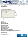
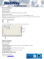
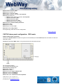
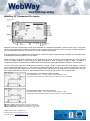
6/16/2011 Alarm panel Interconnections and programming WebWay Mk 4 IP/GPRS + GPRS/PSTN WEBWAYONE LTD, Unit 11 Kingfisher Court Hambridge Road, Newbury, Berkshire. RG14 5SJ 00 44 1635 231 514 [email protected] Introduction This document should be read in conjunction with the WebWay IP/GPRS + GPRS/PSTN Mk 4 hardware guide This alarm panel integration and programming document accompanies the installation and commissioning guide for the WebWay IP/GPRS + GPRS/PSTN. It will allow you to integrate your alarm panel with the WebWayOne series of products for alarm delivery, remote configuration and remote servicing. It is intended that you should be able to complete the programming of the alarm panel and test the alarm signalling without assistance – if you require help, please call our support team – 01635 231514. You will require support from your ARC for checking the successful delivery of Alarms. Once you completed the panel configuration and installation of your WebWay communicator you will have secure remote access to your Alarm Panel over an IP connection from any of your secure locations using WebWay Remote Manager. This will minimise your future site visits and reduce the industry carbon footprint. Please note: If you have a GPRS/PSTN unit the connections and programming for the alarm panels are exactly the same. General troubleshooting notes The WebWay IP/GPRS & GPRS/PSTN Supervised Premises Transceiver (SPT) has the ability to connect to the serial data bus of a wide range of supported Intruder Alarm Panels. Note: Alarms generated by the panel may not be transmitted until Auto Take-On (ATO) has been successfully completed. During the Auto-Take-On process the SPT will be configured with the Panel Type provided during the order process. In order for an SPT to connect to the serial bus of a supported panel the Panel Type must be set correctly. The Panel Type can be changed post commission either remotely by WebWay Support or via the onboard push buttons. Successful serial connectivity using the 485/232/TTL data ports is indicated at the SPT by the “PNL” LED representing a good data link. Red indicates data from the alarm panel to the SPT and green indicates data to the alarm panel from the SPT. The onboard hardwires are not required when a connection to the Serial Bus is used. However they may be utilised in conjunction with the Alarm Panel for environmental alarms or Fire systems. In some cases the Intruder panel may not support a serial interface, but will have a built in Modem (e.g. Aritech CD & ATS systems). A WebWay DCM (Dialler Capture Module) may be used in these circumstances. The DCM emulates the Public Switched Telephone Network (PSTN) providing 40V & Dial-tone at the terminal inputs. Dip switch 7 needs to be set to ON for the DCM to operate. Both the WebWay IP/GPRS and GPRS/PSTN SPTs can be configured (on request) to remove line voltage on the DCM interface if a communications fault to the ARC is detected. Important Note: Under no circumstances should the DCM be removed/ added with Power applied to the WebWay SPT. To test the DCM for functionality a Voltmeter can be connected to the DCM line terminals (La, Lb). The voltmeter should be displaying approximately 40V. A Butt phone can also be connected to listen to the interface and check the following sequence: 1. Panel dials WebWay 2. WebWay responds with a low tone 3. Panel sends sequence of events WEBWAYONE LTD, Unit 11 Kingfisher Court Hambridge Road, Newbury, Berkshire. RG14 5SJ 00 44 1635 231 514 [email protected] DCM Troubleshooting: The panel dials but the DCM doesn’t respond correctly: there may be an issue with the DCM. The panel doesn’t dial the DCM: Connect a Butt phone to the La/Lb interface (DCM) and attempt to dial it (any number will suffice). If the DCM responds with a low tone this confirms the DCM is functioning correctly. Serial BUS Integration If Auto Take-On (refer WebWay IP/GPRS; GPRS/PSTN user manual) has been completed successfully but the alarm panel is not recognising the SPT the Starburst Display and push buttons can be used to view the panel settings that have been loaded into the SPT. The A and B buttons scroll backwards and forwards through the menus whilst the C button is the read/modify button. Scroll through to menu 9; press C once. The Starburst display will read: PANEL = “PANEL TYPE” The “Panel Type” should match the panel you are attempting to connect to the SPT. If this differs or returns “NONE” contact WebWayOne Support (01635 231514). Alternatively you can program the SPT with the relevant “PANEL TYPE” locally using the Push Buttons (A, B, C) and refer to Menu 9. The relevant settings are described within this manual. The panel type is normally specified during the order process, and the relevant information loaded into the Site Information at the ARC. If no panel type is specified at the order process stage the Panel Type will be defaulted to “NONE”. Supported Panels: Galaxy Serial Galaxy Ethernet Galaxy G2 Galaxy External Telecoms Galaxy 16 PLUS Galaxy Digi GE Aritech CD95 GE Aritech CD MPI (RS232) GE Aritech ATS Digi GE Aritech ATS Serial Guardall Guardall Digi Cooper Menvier M series Cooper Menvier TS Series Scantronic 95 EN DSC Risco Castle CareTech Castle Digi Texecom Premier Hardwired Pin Inputs WEBWAYONE LTD, Unit 11 Kingfisher Court Hambridge Road, Newbury, Berkshire. RG14 5SJ 00 44 1635 231 514 [email protected] WebWayOne – Galaxy Integration Brief There are a number of variations in the electrical connectivity to a Honeywell Galaxy Panel from the WebWay SPT. These may depend on the Galaxy Model (e.g. Pre Galaxy G3 models do not have an RS232 Interface). 1. RS232 Emulating an Internal RS232 module (Galaxy G3 and onwards). 2. RS485 connection emulating an Ethernet module (All post Galaxy 16+ models utilising Galaxy S/W V4.0 onwards, G2 panels running Galaxy S/W V1.40 onwards). 3. RS485 connection emulating an External Telecoms module (All models running V1.4 or higher). 4. DCM phone line (Digi) connection emulating a modem as a Telecoms module 5. Hardwired Pin Inputs to the WebWay When connecting to the data bus of a Galaxy using either RS232 or R485 there are several points to consider. Integration RS485 RS232 Full SIA alarms Remote Upload/Download Remote Servicing (automated) Line Fault Monitoring driven by the Galaxy settings Full SIA alarms Remote Upload/Download WebWay Remote Maintenance will not cause disruption when the SPT reboots An SPT re-boot will generate a Missing Com + Key alarm – manager/engineer reset to clear. The bus is monitored 5 times/second. Outputs are required to indicate Line Fault (Relay required). Only G3 and Dimension panels have an internal 232 module by default Automated Remote servicing is not possible RS232 is used as a default setting unless Automated Remote Servicing is required. WEBWAYONE LTD, Unit 11 Kingfisher Court Hambridge Road, Newbury, Berkshire. RG14 5SJ 00 44 1635 231 514 [email protected] Galaxy Serial (RS232) Connections and Configuration Connect the WebWay panel interface 232 R and T to the Galaxy printer interface RX and TX with the reverse of T to RX and R to TX connections. You will also need RTN connected to a GND in the panel. Connect the WebWay PWR + and - to the GND and +12V terminals on the Galaxy Panel. Galaxy G3 panel configuration Galaxy Internal RS232 module Engineer menu 56 Menu 6 - Int RS232 1 Select Mode - Direct Select Format SIA Enter SIA (Option 2), <Level 3(0-4)> Note: it is recommended that the additional Triggers are selected: Select 10 <ON> Select 18 <ON> Enter Account number <_______> Site ID Select Comms Setup Enter Baud rate - 57600 Enter Data bits - 8 Enter Stop bits - 1 Select Parity - No parity Escape to return to Engineer Mode. Exit Engineering fully in order for the panel and the SPT to begin communication. NOTE: The Int RS232 module is not recognised by the Galaxy as a communications module therefore the keypad will not provide a “module added” indication. Back to panel list WEBWAYONE LTD, Unit 11 Kingfisher Court Hambridge Road, Newbury, Berkshire. RG14 5SJ 00 44 1635 231 514 [email protected] Galaxy Ethernet Module Emulation - Connections and Configuration (RS485) Connect the WebWay panel interface RS485 A and B to the Galaxy Dimension connection terminals A and B (Labelled ‘RS485 Line 1’ in the Galaxy Engineer’s Manual PCB Layout). NOTE – Emulation of a Galaxy Ethernet module allows the SPT to be located anywhere on Bus 1. The SPT must be connected to Data Bus 1 and NOT Bus 2. Bus 1 may be marked S1 or S2 on Galaxy 18 Models. You will also need RTN connected to a GND in the panel. Connect the WebWay PWR + and - to the GND and +12V terminals on the Galaxy Panel. Galaxy Ethernet panel configuration The majority of Galaxy Ethernet Module settings may remain at default. In the case of Local and Wide Area Network IP addresses, the WebWay SPT ignores the panel settings. This simplifies installation and provides flexibility with regards to network address changes. It is recommended that a “loop back” address of 127.0.0.1 is configured as the LAN Address, Router Address and Receiver Address. The subnet may default to 255.255.255.0. Go to Menu 56 Select Ethernet Module (Menu 4) Select Alarm reporting (Option 2) Select Format (Option 1) Enter SIA (Option 2), <Level 3(0-4)> Press Enter Under the trigger events settings you define which events the panel will report. Note: it is recommended that the additional Triggers are selected: Select 10 – Settings <ON> (Default OFF) Select 18 – Zone Restorals <ON> (Default OFF) Select Primary IP (Option 2) Set IP Address <127.0.0.1> (blank by default) Enter Port number <10001> (default) Select Account number Enter <_______> (Site ID) Go to Remote Access (Option 3) Select Access Period <Anytime> Select Mode <Direct Access> Use escape to return to Engineer Mode. Exit Engineering fully to allow the Galaxy to recognise the SPT as an Ethernet Comms Module 004. The SPT will also emulate a Keypad, typically Keypad 015 – varies between panels. Back to panel list WEBWAYONE LTD, Unit 11 Kingfisher Court Hambridge Road, Newbury, Berkshire. RG14 5SJ 00 44 1635 231 514 [email protected] Galaxy Ethernet Module Connections and Configuration – G2 – RS485 The WebWay SPT may be used where the Galaxy G2 running software is V1.4 or above. The SPT will emulate a Honeywell Ethernet Module. SPT Emulation of an External Telecoms Module is not supported with the G2. Connect the WebWay panel interface 485 A and B to the Galaxy connection terminals A and B– although the WebWay needs to be on the data bus it is treated as with any other module so it can go anywhere on the bus chain. It must go on Data Bus 1 however, Bus 2 is not supported. You will also need RTN connected to a GND in the panel. Connect the WebWay PWR + and - to the GND and +12V terminals on the Galaxy Panel. Galaxy Ethernet panel configuration A lot of the Default Galaxy settings work fine for us. In the case of IP addresses, the WebWay SPT ignores the panel settings so as not to be overwritten by the panel. This means that any valid IP address will do – our example is 127.0.0.1 Go to Menu 56 Select Ethernet Module (Menu 4) Select Alarm reporting (Option 2) Select Format (Option 1) Enter SIA (Option 2), <Level 3(0-4)> Press Enter Under the trigger events settings you define which events the panel will report. Note: it is recommended that the additional Triggers are selected: Select 10 – Settings <ON> (Default OFF) Select 18 – Zone Restorals <ON> (Default OFF) Select Primary IP (Option 2) Set IP Address <127.0.0.1> (blank by default) Enter Port number <10001> (default) Select Account number (Option 4) Enter <_______> (Site ID) Go to Remote Access (Option 3) Select Access Period <Anytime> Select Mode <Direct Access> Select HW Priority (Option 6) Select Ethernet <1(02)> Select Telecom <0(02)> Select Parameters (Menu 7) Enter System ID < > (Site ID) Use escape to return to Engineer Mode. You need to fully exit Engineering to find the WebWay as a Comms module, we also emulate a Keypad, typically Comms Module 004 and Keypad 015 – varies between panels. Back to panel list WEBWAYONE LTD, Unit 11 Kingfisher Court Hambridge Road, Newbury, Berkshire. RG14 5SJ 00 44 1635 231 514 [email protected] Galaxy External Telecoms Connections and Configuration – RS485 Connect the WebWay panel interface 485 A and B to the Galaxy Dimension connection terminals A and B (Labelled ‘RS485 Line 1’ in the Galaxy Engineer’s Manual PCB Layout). ). NOTE – Emulation of a Galaxy Ethernet module allows the SPT to be located anywhere on Bus 1. The SPT must be connected to Data Bus 1 and NOT Bus 2. Is labelled as S3 on the Galaxy 500 Series Variant. Bus 1 is also available on terminals labelled S1 & S2 on Galaxy 18 series as well as the A & B data line terminations. You will also need RTN connected to a GND in the panel. Connect the WebWay PWR + and - to the GND and +12V terminals on the Galaxy Panel. Galaxy External Telecoms panel configuration Go to Menu 56 Select External Telecoms (Menu 5). Older panels may support an Internal Telecom Module (Menu 1) which may be classed as an External Module. Select Format (Option 1) Enter SIA (Option 2), <Level 3(0-4)> Press Enter Under the trigger events settings you define which events the panel will report. Note: it is recommended that the additional Triggers are selected: Select 10 – Settings <ON> (Default OFF) Select 18 – Zone Restorals <ON> (Default OFF) Select Tel No. 1 (Option 2) Set Phone Number – 01234 567890 (any valid phone number is acceptable) Select Account number (Option 3) Enter <_______> (Site ID) Go to Remote Access (Option 12) Select Access Period <Anytime> Select Mode <Direct Access> Use escape to return to Engineer Mode. You need to fully exit Engineering to find the WebWay as a Comms module, we also emulate a Keypad, typically Comms Module 005 and Keypad 011 – varies between panels. On older panels with no External Telecoms option the Comms Module will be 001. Back to panel list WEBWAYONE LTD, Unit 11 Kingfisher Court Hambridge Road, Newbury, Berkshire. RG14 5SJ 00 44 1635 231 514 [email protected] Galaxy 16 PLUS alarm panel connections and configuration To install the Galaxy 16 Plus for full remote management you will require the Dial Capture Module (DCM). Connect the WebWay Dial Capture Module (DCM) panel interface A and B to the Galaxy 16 Plus connection telephone terminals labelled A and B. Connect the WebWay PWR + and - to the terminals AUX+ and AUX- (Labelled ‘Auxiliary 12V Power Outputs’ in the Galaxy 16 Plus Engineers Manual PCB layout). Galaxy 16 PLUS panel configuration Enter Engineering mode Go to Menu 12 Comms 1 Enter Account number <_______> Site ID (Menu 1) Enter telephone number 1 <01666111> (Menu 2) Select Format (Menu 4) Select SIA Note: it is recommended that the additional Triggers are selected (Menu 7): Select 4 < (black square) Set/Reset> Select Access (Menu 10) Select <Direct> Go to Menu 13 Select < 01 = NO. OF RINGS> Set NO. OF RINGS to 01 Escape to engineer mode – finish. Note that as this is using a dialler no modules will be found by the Galaxy. Back to panel list WEBWAYONE LTD, Unit 11 Kingfisher Court Hambridge Road, Newbury, Berkshire. RG14 5SJ 00 44 1635 231 514 [email protected] Galaxy Digi Telecoms Connections and Configuration To install the Galaxy for full remote management you will require the Dial Capture Module (DCM). Connect the WebWay Dial Capture Module (DCM) panel interface A and B to the Galaxy Line A and B terminals on either the Galaxy Internal or External Dialler module. Connect the WebWay PWR + and - to the GND and +12V terminals on the Galaxy Panel. Galaxy External Telecoms panel configuration Go to Menu 56 Select Internal Telecoms (Option 1) or External Telecoms (Option 5) depending on how you’ve connected the WebWay SPT. Select Format (Option 1) Enter SIA (Option 2), <Level 3(0-4)> Press Enter Under the trigger events settings you define which events the panel will report. Note: it is recommended that the additional Triggers are selected: Select 10 – Settings <ON> (Default OFF) Select 18 – Zone Restorals <ON> (Default OFF) Select Tel No. 1 (Option 2) Set Phone Number – 01234 567890 (any valid phone number is acceptable) Select Account number (Option 3) Enter <_______> (Site ID) Go to Remote Access (Option 12) Select Access Period <Anytime> Select Mode <Direct Access> NOTE – in this integration the SPT is not emulating a Honeywell Communications module, but a Digi device normally used to transmit alarms. This method of integration may be used when the panel firmware is below V1.40. However there are limitations in the SIA events the panel can generate and the use of PIN alarms in conjunction with the serial interface may be required. Back to panel list WEBWAYONE LTD, Unit 11 Kingfisher Court Hambridge Road, Newbury, Berkshire. RG14 5SJ 00 44 1635 231 514 [email protected] GE Aritech CD95 alarm panel connections and configuration To install the Aritech CD95 for full remote management you will the Dial Capture Module (DCM). Connect the WebWay DCM panel interface A and B to the A and B terminals of the RD6203 digital communicator. Connect the WebWay PWR + and - to any relevant Power and Ground terminals. It is recommended that the dialler is defaulted before applying these settings: Aritech CD95 panel configuration Enter engineering mode and enter Digi Code password Go to menu 1 - Tel/account numbers Enter telephone number <01234 567890> (any valid phone number is acceptable) Enter account number <_ _ _ _ _ _> Select Protocol CSI <X SIA> Select U/D Frequency <CCITT> Enter U/D telephone number <123456> Enter U/D account number <_ _ _ _ _ _> Select U/D initiated by PC calls – <Yes)>; User Code – <Yes>; On line – <Yes> Select U/D if armed <Yes> Enter Answer PC rings value <1> Go to menu 2 – Dial Options Select Dialling <DTMF> Select dial tone type <UK> Select Wait dial tone <No> Select Call interval <60> Select Retry period <120> Select Calls for FTC <03> Go to Menu 3 - report options and programme the events required Go to Menu 5 - Protocol Options Select <SIA> Select 1 event per call <Yes> Select 1 account per call <Yes> Select <3 Dig. Event No.> Select SIA Freq. <Bell> WEBWAYONE LTD, Unit 11 Kingfisher Court Hambridge Road, Newbury, Berkshire. RG14 5SJ 00 44 1635 231 514 [email protected] Go to Menu 8 - Line Monitor Select Line monitor <On> Select Off-hook options <Ignore off hook> Select Don’t Answer ringing <Don’t answer ringing> Select Dial Tone test <Yes> Leave dialler and return to engineering mode – finish Back to panel list WEBWAYONE LTD, Unit 11 Kingfisher Court Hambridge Road, Newbury, Berkshire. RG14 5SJ 00 44 1635 231 514 [email protected] GE Aritech CD MPI232 series alarm panel connections and configuration using the WebWay RS232 interface The CD panel will require the MPI232 serial interface module Connections: PWR + PWR 232 T 232 R RTN = = = = = Any relevant +12V or +24V terminal Any relevant ground (OV) Blue Red Green To achieve a connection to the MPI232 serial interface an additional serial cable is required, part number 05 5017. WebWay SPT requirements: The communicator must be running V3.41 firmware or higher Panel type to set = CDMPI Menu 9 Option ? MPI232 panel configuration To access the MPI232 settings connect a PC to the MPI232's DTE serial port. Run up a hyperterminal application set at 9600, None, 8, 1. Set switch 3 on the MPI232 module to OFF. Power up MPI232 module. You will see the following: MPI V2.23 programming main menu =============================== 1. Central station menu 2. Report options 3. Protocol options 0. Exit MPI programming Make your choice: Select 3: Protocol options WEBWAYONE LTD, Unit 11 Kingfisher Court Hambridge Road, Newbury, Berkshire. RG14 5SJ 00 44 1635 231 514 [email protected] Protocol options menu ===================== 1. Modem init string : AT&K0&DE1V1Q0S0=0S7=10 2. Modem dial string : ATD 3. Modem hangup string : ATH 4. Modem connect string : 5. CLID string 1 : 00001 6. CLID string 2 : 00002 7. Baudrate RS-232 port : 9600 8. Baudrate V31bis port : 9600 0. Back to main menu +. Next page -. Previous page Make your choice: Select 5: CLID string 1 and set to '00001' CLID string 1: 00001 Press Enter key Select + Protocol options menu ===================== 1. One account per call : Yes 2. One event per block : Yes 3. Three digit event numbers : No 4. Text in SIA : Yes 5. PA auto-restore : No 6. Dual reporting : No 7. Auto dial : No 8. PC calls : Yes 9. Protocol : V24 0. Back to main menu +. Next page -. Previous page Make your choice: Select 1: One account per call One event per block (Y/N): Select Y Do the same for 2: Select ‘Y’ for One event per block Do the same for 4: Select 'Y' for Text in SIA Do the same for 8: Select 'Y' for PC calls Select + Protocol options menu ===================== 1. Wait for modem reply : 005 2. Wait for modem dial reply : 010 3. Wait for redial : 015 4. Max dial attempts/CS : 240 5. Max modem command attempts: 003 6. Event delay : 020 WEBWAYONE LTD, Unit 11 Kingfisher Court Hambridge Road, Newbury, Berkshire. RG14 5SJ 00 44 1635 231 514 [email protected] 7. DCD timeout : 255 0. Back to main menu +. Next page -. Previous page Make your choice: Do the same for 7: Set value to 255 for DCD timeout. This disables DCD timeout Select 0 to go back to main menu: Select 1: Central Station menu Central station menu ==================== 1. Central station 1 2. Central station 2 3. Central station 3 4. Central station 4 5. Up/download menu 0. Back to main menu Make your choice: Select 1: Central station 1 Central station 1 menu ====================== 1. Account code 1 : 1111101 2. Account code 2 : 1111102 3. Account code 3 : 1111103 4. Account code 4 : 1111104 5. Account code 5 : 1111105 6. Account code 6 : 1111106 7. Account code 7 : 1111107 8. Account code 8 : 1111108 9. Network address: 511100 0. Back to Central Station menu Make your choice: Select 9: Network address and make sure there are 6 or more digits. They can be any combination. Select 0 until you are at the main menu Select 0: Exit MPI programming and follow instructions Turn PC-programming dip-switch 3 on to exit. Goodbye. Last and crucial, make sure switch 5 on the MPI232 moduke is set to OFF. This turns off callback mode. Back to panel list WEBWAYONE LTD, Unit 11 Kingfisher Court Hambridge Road, Newbury, Berkshire. RG14 5SJ 00 44 1635 231 514 [email protected] GE Aritech ATS series alarm panel connections and configuration using the WebWay Dial Capture Module (DCM) GE Aritech ATS 2000/3000/4000 /4500 To install the Aritech ATS for full remote management you will require the Dial Capture Module (DCM). Connect the WebWay PSTN panel interface A and B or the A and B terminals on the WebWay DCM to the PSTN A and B terminals on the ATS panel. Connect the WebWay PWR + and - to any relevant Power and Ground terminals. Aritech ATS series panel configuration Select advanced service menu Got to menu 9 Ensure PBX is blank Ensure MSN is blank Select Dial tone detection <UK> Select DTMF tone dialling <YES> Select Enable PSTN line fault monitor <NO> Select Monitor Service tones <NO> Select Use 3 digit SIA extensions <YES> Select ISDN point to point <NO> Select 200 baud reverse area open/close <NO> Select X25 TEI value <2> Select Audio listen in time <180> Select Audio listen in frame time <30> Select Report mains fault <YES> Select Report line fault <YES> Select Enable GSM line fault monitor <NO> Select the central station to program <Central station 1> Select the reporting format <X-SIA Large> (Option 7) Enter the first phone number <01234 567890> (any valid phone number is acceptable) Enter the system account number <______> (Site ID/Account Number) Select BELL modem tones for SIA <YES> Enter the Area account number <______> (Site ID/Account Number) Select Dual reporting <NO> Select Listen in <NO> Select Disable reporting of inhibits <NO> WEBWAYONE LTD, Unit 11 Kingfisher Court Hambridge Road, Newbury, Berkshire. RG14 5SJ 00 44 1635 231 514 [email protected] Select Reserved <NO> Select X-SIA Max Characters <30> Select X25 account code <not set> Select X25 line type <0> Select Connection type <0 PSTN> Select Suppress FTC for voice reporting <NO> Select Retry count <10> Go to menu 29 Select Enable remote up/download <YES> Select Up/Download if any area armed <YES> Select Enable remote control <YES> Select Remote control if any area armed <YES> Select Use modem init string <NO> Select Report alarms to computer <NO> Select Report access events to computer <NO> Enter Computer address <0001> Enter Security password <0000000000> Select Security attempts <255> Select Number of rings before answering <1> Select Number of calls before answering <0> Select Answer machine defeat <NO> Select Reserved <NO> Select Use Bell 103 protocol <NO> Select Connection type <0 PSTN> Back to panel list WEBWAYONE LTD, Unit 11 Kingfisher Court Hambridge Road, Newbury, Berkshire. RG14 5SJ 00 44 1635 231 514 [email protected] GE Aritech ATS series alarm panel connections and configuration using the WebWay RS232 interface ATS 3000/4000/4500 series The ATS panel will require the ATS1801 serial interface module Connect the WebWay panel interface 232 T, R, PWR - (Ground) and PWR + to the Computer port RXD, TXD, GND and CTS (+12 Volts) on the ATS panel – note T to RXD and R to TXD. As the Webway can draw power from this connection there is no need for additional wiring. Aritech ATS series panel configuration Select advanced service menu Got to menu 9 Ensure PBX is blank Ensure MSN is blank Select Dial tone detection <UK> Select DTMF tone dialling <YES> Select Enable PSTN line fault monitor <NO> Select Monitor Service tones <NO> Select Use 3 digit SIA extensions <YES> Select ISDN point to point <NO> Select 200 baud reverse area open/close <NO> Select X25 TEI value <2> Select Audio listen in time <180> Select Audio listen in frame time <30> Select Report mains fault <YES> Select Report line fault <YES> Select Enable GSM line fault monitor <NO> Select the central station to program <Central station 1> Select the reporting format <X-SIA Large> (Option 7) Enter the first phone number <01234 567890> (any valid phone number is acceptable) Enter the system account number <______> (Site ID/Account Number) Select BELL modem tones for SIA <YES> Enter the Area account number <______> (Site ID/Account Number) Select Dual reporting <NO> Select Listen in <NO> WEBWAYONE LTD, Unit 11 Kingfisher Court Hambridge Road, Newbury, Berkshire. RG14 5SJ 00 44 1635 231 514 [email protected] Select Disable reporting of inhibits <NO> Select Reserved <NO> Select X-SIA Max Characters <30> Select X25 account code <not set> Select X25 line type <0> Select Connection type <4 Universal Interface> Select Suppress FTC for voice reporting <NO> Select Retry count <10> Go to menu 29 Select Enable remote up/download <YES> Select Up/Download if any area armed <YES> Select Enable remote control <YES> Select Remote control if any area armed <YES> Select Use modem init string <NO> Select Report alarms to computer <NO> Select Report access events to computer <NO> Enter Computer address <0001> Enter Security password <0000000000> Select Security attempts <255> Select Number of rings before answering <1> Select Number of calls before answering <0> Select Answer machine defeat <NO> Select Reserved <NO> Select Use Bell 103 protocol <NO> Select Connection type <4 Universal Interface> Back to panel list WEBWAYONE LTD, Unit 11 Kingfisher Court Hambridge Road, Newbury, Berkshire. RG14 5SJ 00 44 1635 231 514 [email protected] Guardall alarm panel connections and configuration WebWay communicators/SPTs are connected to alarm panels in order to enable fast and secure transmission of detailed alarm messages using WebWay’s unique Virtual Private Security Network (VPSN). The communicators provide further benefits to installers including carrying out remote upload/download (when possible with the panel range) whilst simultaneously sending alarms and network availability monitoring of each connection using WebWay’s unique Network Quality of Service analytics (NQoS). All communicators are certified by the British Research Establishment and the Loss Prevention Certification Board and are accepted by all insurance companies. Integration Requirements: Serial DCM Panel Modules Required RX16i, QX 32i, QX 18, QX18i, QX34, QX34i, PX18, PX34, PX48i, PX80, PX80i, PX250HS, PX500 No modules required (all integrated): RX16i, QX32i, QX18, QX18i, QX34, QX34i, PX48i, PX80i RX16i, QX 32i, QX 18, QX18i, QX34, QX34i, PX18, PX34, PX48i, PX80, PX80i, PX250HS, PX500 No modules required (all integrated): RX16i, QX32i, QX18i, QX34i, PX48i, PX80i Panel Software Required SPT Modules Required Guardall RS232 serial module is required on: PX500, PX250HS, PX18, PX34, PX80 V4.20 None Guardall external dialler module is required on: PX500, PX250HS, QX18, QX34, PX18, PX34, PX80 V4.00 Dial Capture Module (DCM) Guardall Serial Cable 05-5032, Power source (12V/24V) V3.36 (minimum), V3.41 (recommended) GSR (any version) Cable pair for dialler, Power source (12V/24V) V3.40 GSR (any version) Panel Ranges Supported SPT Cables Required SPT Firmware Required Panel UDL Software Required WebWay UDL Software Required Remote Manager V2.1.1.1 or higher Remote Manager V2.1.1.1 or higher Additional Requirements Guardall GSR Serial Dongle* Guardall GSR Serial Dongle* * Please be aware this needs configuring the the WebWay SPT and the Guardall panel UDL (Upload/Download) description When connected to a WebWayOne communicator Remote Access will be possible into the alarm panel. The tools required are detailed above and the panel configuration is detailed later in this document. In effect for both alarms and UDL the WebWay SPT is taking the place of a GSR module. There are strict security controls in place with the system where the only access possible is via the secure VPSN that a WebWay provides. Authorisation for access must be approved by the ARC involved and only those using the WebWay Remote Manager software will be able to gain access. On top of this there are the usual security methods in place that a GSR connection would have – you need to have a GSR dongle and a valid copy of the UDL software. *Contact Product Support for more information. Please note-Remote Manager Software is always required for UDL. Connection of the SPT to the Guardall: Connect the 9 way connector cable to the Guardall RS232 port on either the main board assembly or the external RS232 module and the cable wires to the WebWay SPT as detailed in the table below. Important: Please note which Serial module you have connected to (if there are multiple) in order to make sure the panel programming matches. Please Note: For a serial connection the GSR dongle Serial number needs configuring in the WebWay SPT as well as in the alarm panel. This can be done through menu G in the same manner as for “Auto Take-On” which uses menu D. WEBWAYONE LTD, Unit 11 Kingfisher Court Hambridge Road, Newbury, Berkshire. RG14 5SJ 00 44 1635 231 514 [email protected] Mk 3 SPT Serial Number 54- or 55-xxxxxx-1 Note: Jumpers should be set to RS232 WebWay SPT 9 way Connector colours A Yellow Black Green B GND Red – Any +12V Terminal at Alarm Panel Mk 4 SPT Serial Number 56-xxxxxx-1 WebWay SPT 9 way Connector colours 232 T Yellow Black Green 232 R RTN Red – Any +12V Terminal at Alarm Panel Items to Check Menu 13 – Check that a module has been selected, either 0=SMO or 1=SM1, alternatively Dialler has been selected. If not set Menu’s 11 & 12 will not be accessable. SPT – Make sure the parameter GUARDALL_PANEL_TIMEOUT has not been programmed, if it has, remove any values associated. Check the fuse on the Serial Module is operational. If you have configured the panel for a DCM connection and despite the panel set up being correct, the panel is not dialling out; reboot the panel. If the GSR is not present in Menu 12; then it should appear in Menu 20. Guardall alarm panel configuration for all ranges Select menu 11 telephone number 1 Select Tel Number <1> Enter Tel Number <01234 567890> (any valid phone number is acceptable) Select Module <SM 0> This is valid for those panels which include an integrated module. For the external modules on the legacy range you will need SM 1. Select Assist <Off> Select Format <Guardall> Select Auto Test <Off> Select Attempt <3> Select Backup <0> Select Call Repeat <Off> Select GSR <1> Select Alarm <On> Select Set/Unset <On> Select Bypass <On> Select Trouble <On> Select Log On <On> Select Eng On <On> Select Reset <On> Select Restore <On> Press X button twice WEBWAYONE LTD, Unit 11 Kingfisher Court Hambridge Road, Newbury, Berkshire. RG14 5SJ 00 44 1635 231 514 [email protected] Select menu 12 GSR 1 Enter S/N <______> (GSR dongle Serial number) (This needs configuring in the SPT) Enter GSR ID <Communicator Site ID> Select Enable <Auto> Select CallBack <Off> Select Reset <On> Select Unset <On> Select Code <On> Select Time <On> Select Bypass <On> Select Soak <On> Select Log <On> Select Config RD <On> Select Config WR <On> Select PINs RW <Off> Select A. Log Upload <0> Select Exit Time <1> Select KP Message <On> Select Virtual KP <On> Press X button once Press 20 for system Select Area ID Enter <0> Select system <Communicator ID (Last 4 digits of Site ID)> Enter <1> Select Area 1 <Communicator ID (Last 4 digits of Site ID)> Press X button four times Select 05 to log out Back to panel list WEBWAYONE LTD, Unit 11 Kingfisher Court Hambridge Road, Newbury, Berkshire. RG14 5SJ 00 44 1635 231 514 [email protected] Connections to Guardall (DIGI) with the Webway DCM RX16i, QX32i, PX48i and PX80i PX500 and PX250HS QX18i and QX34i QX18 and QX34 PX18, PX34 and PX80 includes an integrated dialler does not include an integrated dialler – an external one is required on the panel includes an integrated dialler does not include an integrated dialler – an external one is required on the panel does not include an integrated dialler – an external one is required on the panel Digital communicator connection Connect the A and B ‘PSTN’ terminals and ground on the WebWay to the A and B telephone connections on the Guardall alarm panel. Connect the WebWay PWR + and - to any relevant Power and Ground terminals. Guardall alarm panel configuration for all ranges Select menu 11 telephone number 1 Select Tel Number <1> Enter Tel Number <01234 567890> (any valid phone number is acceptable) Select Format <SIA> Select Module <Int. Dlr.> - this will be Ext. Dlr if an external dialer module was required on the panel Select Auto Test <Off> Select Attempt <0> Select Backup <0> Select Alarm <On> Select Set/Unset <On> Select Bypass <On> Select Trouble <On> Select Log On <On> Select Eng On <On> Select Reset <On> Select Restore <On> Press X button twice Select menu 12 GSR 1 Select Enable <Auto> Enter S/N <______> (GSR dongle Serial number) Enter GSR ID <Communicator Site ID> WEBWAYONE LTD, Unit 11 Kingfisher Court Hambridge Road, Newbury, Berkshire. RG14 5SJ 00 44 1635 231 514 [email protected] Enter IP Addr <0> Select CallBack <Off> Select Reset <On> Select Unset <On> Select Code <On> Select Clock <On> Select Bypass <On> Select Soak <On> Select Log <On> Select Config RD <On> Select Config WR <On> Select PINs RW <Off> Select A. Log Upload <0> Select Exit Time <1> Select KP Message <On> Select Virtual KP <On> Select Poll time <0> Select X button once Press 20 for system Select Area ID Enter <0> Select system <Communicator ID (Last 4 digits of Site ID)> Enter <1> Select Area 1 <Communicator ID (Last 4 digits of Site ID)> Press X button four times Select 05 to log out Back to panel list WEBWAYONE LTD, Unit 11 Kingfisher Court Hambridge Road, Newbury, Berkshire. RG14 5SJ 00 44 1635 231 514 [email protected] Cooper Menvier alarm panel connections and configuration Cooper Menvier M Series M1000, M2000 The M Series main board assembly has a 9 way D-type connector at the top right. This connects to the R, T and RTN terminals of the WebWayOne panel interface. The connection details are as follows: 9 way D-type WebWayOne 2424 2 T (Blue) 232 3 R (Red) 232 5 RTN (Green) Connect the WebWay PWR + and - to any relevant Power and Ground terminals. Go to menu 2-5-2 Communications 2 Digicom ARC No 1 Select telephone number <01234 567890> (any valid phone number is acceptable) Select account number <______> Select dialling mode <consecutive> Select restore signals <enable> Select FF channels <8FF channels> Select CID/SIA reports <Full> Go to menu 2-5-4 Communications 4 RS232 options Select RS232 baud <38400> Select remote modem <enable> Go to menu 2.5.1 Communications 1 downloader Select Password <______> (same as configured in downloader application) Select site ID <______> (same as configured in downloader application) Select access mode <unattended> Select edit call Nos <not configured> Select rings to answer <immediate> Select baud rate <1200> Select 51:Downloader - Modem options - Ans Phone Defeat <Disabled> Back to panel list WEBWAYONE LTD, Unit 11 Kingfisher Court Hambridge Road, Newbury, Berkshire. RG14 5SJ 00 44 1635 231 514 [email protected] Cooper Menvier TS Series TS690, TS790, TS900, TS2200,TS2500 Select the jumper settings for TTL. Connect the WebWay panel interface R, T and RTN using the supplied molex cable. This goes T- red R-Green RTNBlue and it plugs onto the 8 way Molex type connector labelled ‘Digi-Modem’. This is where the DC58 module would normally be plugged in. Connect the WebWay PWR + and - to any relevant Power and Ground terminals. TS 690 panel Configuration: Engineer menu 2-C – Modem options 1 Callback No 1 123456 2 Callback No 2 No setting 3 Callback No 3 No setting 4 Password This must match the password configured in the Downloader application account setup 5 Modem site No This must match the site ID configured in the Downloader application account setup 6 Telephone No 1 No setting Telephone No 2 No setting Account No 1 No setting Account No 2 No setting Reports 1 No setting Reports 2 No setting Set/Day No setting Restore No setting 7 Digi, Idle No setting If you need to configure the panel type yourself: Menu 9 option 1 – PANEL = TS690 TS 790/900/2500 panel Configuration: Engineer menu 2-C – Modem options WEBWAYONE LTD, Unit 11 Kingfisher Court Hambridge Road, Newbury, Berkshire. RG14 5SJ 00 44 1635 231 514 [email protected] 1 Callback No 1 123456 2 Callback No 2 No setting 3 Callback No 3 No setting 4 Password This must match the password configured in the Downloader application account setup 5 Modem site No This must match the site ID configured in the Downloader application account setup 6 Digi Programming Telephone No 1 <01234 567890> - any number not 123456 Telephone No 2 No setting required Telephone No 3 No setting required Account No 1 <account number> Account No 2 No setting required Account No 3 No setting required Reports to No 1 Set all reports on Reports to No 2 Set all reports on Reports to No 3 Set all reports on Set/Day Set all reports on Restore Set all reports on Invert Set all reports on Dialling mode Consecutive Test call period Disabled Digi output 1 is Line fault Digi output 2 is Line fault Extended format Full report TOS calls are Disabled Ring count is Instant Press ‘0’ to protect numbers – Do not select Back to panel list WEBWAYONE LTD, Unit 11 Kingfisher Court Hambridge Road, Newbury, Berkshire. RG14 5SJ 00 44 1635 231 514 [email protected] Scantronic S95EN Scantronic S95EN installation The S Series main board assembly has a 9 way D-type connector at the top right. This connects to the R, T and RTN terminals of the WebWayOne panel interface. The connection details are as follows: 9 way D-type 2 3 5 WebWayOne 2424 T (Blue) 232 R (Red) 232 RTN (Green) Connect the WebWay PWR + and - to any relevant Power and Ground terminals. Scantronic S95EN configuration Go to Menu 52 Digicom Select comms format <SIA 3> Select ARC no. <01234 567890> (any valid phone number is acceptable) Select account No <______> (ignore account numbers 2-8) Select dialing mode <Consecutive> Select digicom options Select Restore signals <enable> Select FF channels <8 FF channels> Select Line fault <enable> Go to Menu 53 – RS232 options Select RS232 option baud <38400> Select Remote modem <enable> Go to menu 51 Select serial number <______> Select account name <______> Select Access mode <unattended> Select Edit call Nos <not configured> Select Modem options rings to answer <immediate> Select Baud rate <1200> Select Downloader - Modem options - Ans Phone Defeat <Disabled> Back to panel list WEBWAYONE LTD, Unit 11 Kingfisher Court Hambridge Road, Newbury, Berkshire. RG14 5SJ 00 44 1635 231 514 [email protected] DSC Alarm panels Power Series PC1616/PC1832/PC1864 MAXSYS PC4020 Applications supported SIA alarm transmission Remote upload/download via WebWay ATS and WebWay Remote Manager Power series PC1616/PC1832/PC1864 installation using the WebWay Dial Capture Module (DCM) Connect the WebWay PSTN panel interface A and to the A and B terminals of the DSC control panel. Connect the WebWay PWR + and - to the Aux + and Aux - of the DSC control panel. Maxsys PC4020 series installation using the WebWay dial capture Connect the WebWay PSTN panel interface A and B (location 6 in figure 1 (or to the DC option board - terminals A and B) to the A and B terminals of the DSC control panel. Connect the WebWay PWR + and - to the Aux + and Aux - of the DSC control panel. On the Panel PC1616/PC1832/PC1864 Go to section 301: Enter telephone number <01234 567890> (any valid phone number is acceptable) Go to section 310: Enter account number <______> Go to section 350: Enter communicator format to SIA <04> Go to section 380: Ensure option 1 is enabled to <1________> Go to section 381: Ensure options 5 & 6 are enabled - the rest clear <____56__> Go to section 382: All must be clear <_________> Go to section 401: Option 1 must be set - the rest clear<1________> Go to section 403: Enter DLS access code <______> Go to section 404: Enter DLS panel identification code <______> Go to section 406: Set number of rings to <002> Back to panel list WEBWAYONE LTD, Unit 11 Kingfisher Court Hambridge Road, Newbury, Berkshire. RG14 5SJ 00 44 1635 231 514 [email protected] Risco Alarm panels ProSys 40, ProSys 128 Applications supported SIA alarm transmission Remote upload/download via WebWay ATS and WebWay Remote Manager Physical connection details Select Dip switch 10 to ON (bottom left corner of the PCB) for a Terminated RS485 connection Connect the A, B, and gnd terminals of the WebWayOne to connector J1 on the ProSys alarm panel. Use either the WebWay provided cable or make to suit. The connection details are as follows: Bus 2 WebWayOne 2424 YEL A GRN B COM RTN Connect the WebWay PWR + and - to any relevant Power and Ground terminals. WebWayOne configuration Environment variable settings PANEL_TYPE = RISCO Button menu 9, option L Panel configuration The following configuration stages have to be completed to add the WebWayOne to the panel. 1) Adding the ACM Module 2) Set up the ACM Module 3) Set up the Communication Path IP Addresses and Port numbers 4) Set up Account Numbers 5) Set up Alarm Format 6) Ensure Upload/Download Communication is not encrypted 7) Enable Upload/Download 8) Disable Callback on Upload/Download 9) Enable Upload/Download through GSM WEBWAYONE LTD, Unit 11 Kingfisher Court Hambridge Road, Newbury, Berkshire. RG14 5SJ 00 44 1635 231 514 [email protected] 10) Select DigiCom SIA Codes 1) Adding the ACM Module Go into Installer Mode: Press: [*] [7] [#] Enter Installer or Grand Master code (or both as requested - depends on state of panel) (Panel is now in Installation mode) Menu Shows: "Engineer Prog" "1) System" Press: [7] - to go to the Install Menu Menu Shows: "Install" "Add/Del Module" Press: [1] - to enter the Add/Del Module Menu Menu Shows: "Add a Module" "Keypad" Press: [9] - to select second selection of modules Menu Shows: "Add a Module" "GSM" Press: [3] - to select ACM Press: [Part Set - to toggle selection Menu Shows: "ACM Module" "Type=ACM1" Press: [#] - to accept Press: [*] repeatedly - to exit back to top menu 2) Set up the ACM Module – following on from 1) Menu Shows: "Engineer Prog" "Install" Press: [8] - to go to devices setup Menu Shows: "Devices:" "ACM" Press: [#] - to enter ACM setup Menu Shows: "ACM" "ACM Params" Press: [#] - to go into ACM Params Menu Shows: "ACM Params" "ACM IP Addr" Press: [#] - to set the ACM IP address Menu Shows: "ACM IP Addr" "000.000.000.000" Enter the IP address for the Communicator (or 127.000.000.001 to use DHCP) using arrow keys and digits Press: [#] - to accept Press: [Omit] - (down cursor) to go to subnet mask Menu Shows: "ACM Params" "Subnet IP Msk" Press: [#] - to change subnet mask Menu Shows: "Subnet IP Mask" "255.255.255.000" Enter the subnet mask for the Communicator using arrow keys and digits Press: [#] - to accept Press: [Omit] - (down cursor) to go to gateway IP Menu Shows: "ACM Params" "Gateway IP" Press: [#] - to change gateway IP Menu Shows: "Gateway IP Addr" "000.000.000.000" Enter the IP Address for the local network's default gateway/router (or 127.000.000.001 to use DHCP) using arrow keys and digits Press: [#] - to accept Press: [Omit] - (down cursor) to go to gateway IP Press: [*] repeatedly - to exit back to top menu 3) Set up the Communication Path IP Addresses and Port numbers – following on from 2) Menu Shows: "Engineer Prog." "Devices:" Press: [5] - to enter DigiCom setup Menu Shows: "Digicom" "Link up" Press: [#] - to Enter Digicom Link-up Menu Shows: "Link-Up" "ARC Link-Up" Press: [#] - to Enter ARC Link-Up Menu Shows: "ARC Link-Up" "ARC 1 Link-Up" Press: [#] - to Enter ARC 1 Link-Up WEBWAYONE LTD, Unit 11 Kingfisher Court Hambridge Road, Newbury, Berkshire. RG14 5SJ 00 44 1635 231 514 [email protected] Menu Shows: "ARC 1 Channel" "PSTN" or "IP" Press: [omit or status]- (up/down cursor) to select IP Press: [#] - to enter IP setup Menu Shows: "ARC 1 IP Addr" "000.000.000.000" Enter the IP address of the first gateway path using arrow keys and digits. Set to 127.000.000.001 if address programmed in the WebWayOne is not be overridden by the panel. Press: [#] - to accept change ([*] to cancel) Menu Shows: "ARC 1 IP Port" "030303" Enter 50561 (or other port number for gateway) Press: [#] - to accept Press [omit] - (down cursor) for ARC 2 Repeat process for ARC 2 and ARC 3. Press: [*] - to exit back to main DigiCom menu 4) To set up Account Numbers – following on from 3) Menu Shows: "DigiCom" "Link-Up" Press: [2] - to go to accounts Menu Shows: "DigiCom" "Accounts" Press: [#] - to enter Menu Shows: "Cust. Accounts" "Partition 1" Press: [#] - to enter Menu Shows: "Account P:1" "For ARC 1" Press: [#] - to enter Enter you account code using cursors and digits (six digits - can't get rid of leading zeros) Press: [#] - to accept Menu Shows: "Apply Accnt P:1" "xxxxxx to All? Y" Press: [#] - to accept (or [omit] to toggle to no first Press: [*] repeatedly to exit back to DigiCom Menu 5) To set up Alarm Format – following on from 4) Menu Shows: "DigiCom" "Accounts" Press: [3] - to select comm format Menu Shows: "Comm Format" "For ARC 1" Press: [#] - to enter Menu Shows: "For Arc " "Format 0000" Enter: 0700 - using number keys to select SIA format Press: [#] - to accept Repeat process for ARC 2 and ARC 3. Press: [*] repeatedly to exit back to DigiCom Menu 6) To Ensure Upload/Download Communication is not encrypted – following on from 5) Menu Shows: "DigiCom" "Comm Format" Press: [4] - to select access code Menu Shows: "Access & ID" "Access Code" Enter: [#] - to enter access code Menu Shows: "Access Code" "Code 5678" Enter: 5678 - this must also be set in the UDL package (it is the default) Press: [#] - to accept Menu Shows: "Access & ID" "Access Code" Press: [2] - to Change Remote ID code Menu Shows: "Remote ID Code" "Code: 0001" Enter: 0000 - to ensure UDL comms is not encrypted Press: [#] - to accept Press: [*] repeatedly to exit back to DigiCom Menu 7) To Enable Upload/Download – following on from 8) Menu Shows: "DigiCom" "Access & ID" WEBWAYONE LTD, Unit 11 Kingfisher Court Hambridge Road, Newbury, Berkshire. RG14 5SJ 00 44 1635 231 514 [email protected] Press: [5] - to select Digicom Control Menu Shows: "Dial Control" "ARC enable Y" Press: [0][3] - to select U/D enable Menu Shows: "Dial Control" "U/D/Enable N" Press: [Part Set] - if necessary to enable 'Y' Press: [#] - to accept Menu Shows: "DigiCom:" "Control" Press: [5] - to select Digicom Control Menu Shows: "Dial Control" "ARC Enable" Press: [0][8] - to select U/D callback enable 8) To Disable Callback on Upload/Download – following on from 7) Menu Shows: "Dial Control" "U/D/ callback N" Press: [Part Set] - if necessary to enable 'N' Press: [#] - to accept Menu Shows: "DigiCom:" "Control" Press: [5] - to select Digicom Control 9) To Enable Upload/Download through GSM – following on from 8) Menu Shows: "Dial Control" "ARC Enable" Press: [1][4] - U/D GSM enable Menu Shows: "Dial Control" "U/D GSM ENB Y" Press: [Part Set] - if necessary to enable 'Y' Press: [#] - to accept Press: [*] to get back to main DigiCom menu 10) To select DigiCom SIA Codes – following on from 9) Menu Shows: "DigiCom" "Link-Up" Press: [0] - to go to Auto codes Menu Shows: "DigiCom" "Contact ID" Press: [2] - to select SIA Menu Shows: "SIA Codes" "Auto Allocat? N" Press: [Part Set] - to toggle to 'Y' Press: [#] Back to panel list WEBWAYONE LTD, Unit 11 Kingfisher Court Hambridge Road, Newbury, Berkshire. RG14 5SJ 00 44 1635 231 514 [email protected] Castle CareTech alarm panels EuroONE EuroONE Plus Serial interface connection Connect the RS232; R &T terminals and RTN on the WebWay to the MSX-5 Expansion Card that should be located in the Expansion Card slot on the Euro-ONE and Euro-ONE Plus panel. The connector is not labeled, however the connections are from right to left PIN 1 Black, PIN 2 White, PIN 3 Red. WebWay connections are PIN T White, PIN R Red and RTN Black. Connect the WebWay PWR + and - to any relevant Power and Ground terminals. EuroONE alarm panel configuration - serial mode Go to Engineering Mode Go to programme Digi/SMS calls Select Disable Digi/SMS <0> Select ARC Details <1> Select Active <Yes> Select format <WebWayOne IP> (Option 141) Select SIA Ack Char <006> Select SIA Nack Char <021> Select valid areas <select areas to be reported> Select stop on success <yes> Select ARC account <No> Select content 1-16 <Trigger events> (recommend 1-5, and 7-13) Select content 17-32 <Trigger events> (recommend 21-25, 27-30, and 32) Select redials <03> Select time out <15> Select test calls <No> Note: The recommended Content settings will send the most relevant event reports. Some installations may require less event types to be activated. Refer to the Castle documentation for more information. Go to ‘set up downloading’ Select download by <IP> Select poll timeout <10> WEBWAYONE LTD, Unit 11 Kingfisher Court Hambridge Road, Newbury, Berkshire. RG14 5SJ 00 44 1635 231 514 [email protected] Select modem init tmout <060> Select rings to answer <1> Select comm. Tx timeout <030> Select ARMPC telephone number <not required> Select program PCs <1> Select modem telephone number <not required> Select signal alarms <No> Select signal faults <No> Select signal set/unset <No> Select signal access code <No> Select password <optional UDL password> Select redials <03> Select time out <00> Select stop on success <No> Select dial mode <retry same> Exit engineering mode and save the configuration Back to panel list CASTLE alarm panel configuration - DIGI mode Digital communicator connection Connect the A and B ‘PSTN’ terminals and ground on the WebWay to the A and B telephone connections on the Euro ONE alarm panel. Connect the WebWay PWR + and - to any relevant Power and Ground terminals. Go to Engineering Mode Go to programme Digi/SMS calls Select Disable Digi/SMS <0> Select ARC Details <1> Select Active <Yes> Select format SIA <SIA 3> (Option 129) Select first number <01666111> Select first number <01666222> Select valid areas <select areas to be reported> WEBWAYONE LTD, Unit 11 Kingfisher Court Hambridge Road, Newbury, Berkshire. RG14 5SJ 00 44 1635 231 514 [email protected] Select stop on success <yes> Select ARC account <No> Select content 1-16 <Trigger events> (recommend 1-5, and 7-13) Select content 17-32 <Trigger events> (recommend 21-25, 27-30, and 32) Select redials <03> Select time out <15> Select test calls <No> Note: The recommended Content settings will send the most relevant event reports. Some installations may require less event types to be activated. Refer to the Castle documentation for more information. Go to ‘set up downloading’ Select download by <modem> Select security mode <auto-answer> Select telecom line <dedicated> Select number of rings <3> Select modem speed <high> Select ARMPC telephone number <123456> Select program PCs <1> Select modem telephone number <123456> Select signal alarms <No> Select signal faults <No> Select signal set/unset <No> Select signal access code <No> Select password <optional UDL password> Select redials <03> Select time out <00> Select stop on success <No> Select dial mode <retry same> Exit engineering mode and save the configuration Go to Site options Select ATE inputs <STU> Back to panel list WEBWAYONE LTD, Unit 11 Kingfisher Court Hambridge Road, Newbury, Berkshire. RG14 5SJ 00 44 1635 231 514 [email protected] TEXECOM Premier alarm panel connections and configuration 88/168/640 The panel software version must be 6.x or above. Connect the WebWay panel interface (TTL) R, T and RTN using the supplied molex cable. This goes T- red R-Green RTN-Blue and it plugs onto Com port 1. Connect the WebWay PWR + and - to any relevant Power and Ground terminals. The texecom panel configuration is uploaded via the Wintex software and downloaded to the panel on com port 2 from a local PC. The only thing to configure in the panel is enabling upload/download if required Key settings in the communications menu are: In Options: Enable communicator must be ticked UDL passcode (set in the panel) must match. Dial attempts 1, ring before answer 3 In ARC’s: Account number (site ID) SIA Level 2/3 Connect Via IP - ticked Send SIA text - ticked In Radio-Pad and Com Port options: Com Port 1 – WebWayOne module Local IP address 127.0.0.1 Local IP port 50561 Gateway 127.0.0.1 Subnet Mask 255.255.255.0 Name/SMG port 50561 Back to panel list WEBWAYONE LTD, Unit 11 Kingfisher Court Hambridge Road, Newbury, Berkshire. RG14 5SJ 00 44 1635 231 514 [email protected] WebWay SPT Hardwired Pin Inputs WebWay devices are shipped with 16 pin inputs available as a standard configuration. These can be used in conjunction with any serial/DCM panel integration and used to send supplementary events such as Fire, Freezer, Smoke detection or environmental alarms that are not normally connected via the Intruder System. A full pins/hardwire only installation should be used as a last resort where full SIA and UDL capability is not possible (refer to WebWayOne Panel integration for more detail). When electrically connected the WebWay device is looking for a change of voltage on each individual pin. There is a hard control to decide whether a POS (+12V) or a NEG (0V) BIAS is used to indicate change of state. In addition a configuration profile is downloaded to the SPT and used to determine which state indicates an alarm or restore state. For the hard control there are 2 settings that should be checked: Jumper J3 (just below the main display) is used to control HIGH/LOW BIAS of pins 1-8. The control of HIGH/LOW BIAS for pins 9-16 is set using Dip Switch 8 (No 8 of SW4). When set to HIGH BIAS the pins have a floating voltage and should be grounded (0V) to change state. They will also change state when the 0V is lost. With LOW BIAS the pins sit at 0V and require +12V to change state. Hard wired Inputs 1-16 configured as simple high inputs Input threshold high to low 2.0V DC (maximum Input voltage: 30V DC) If required the alarm and restore conditions may be reversed in the SPT configuration Hard wired Inputs configured as simple low inputs Input threshold low to high 4.0V DC (maximum Input voltage: 30V DC) If required the alarm and restore conditions may be reversed in the SPT configuration Hard wired PIN Inputs PIN Input - Tamper configured as for simple low or high inputs PIN Input - Battery fail configured as for simple low or high inputs PIN Input - Mains fail configured as for simple low or high inputs WEBWAYONE LTD, Unit 11 Kingfisher Court Hambridge Road, Newbury, Berkshire. RG14 5SJ 00 44 1635 231 514 [email protected] The Pin Sense Control determines which state indicates an alarm or restore condition (loaded on Auto Take-On). Terminology Negative Removed Negative Applied Positive Removed Positive Applied Voltage Alarm 3.4V/6.9V 0V 0V 12V Voltage Restore 0V 3.4V/6.9V 12V 0V Pin Sense Negative Positive Positive Negative BIAS HIGH HIGH LOW LOW Due to the different BIAS controls for pins 1-8 and 9-16 the floating Pin Voltage is different. 1-8 float at 3.4V and 9-16 float at 6.9V (measured from a 0V source). The interpretation of the above terminology does vary within the industry, however in this instance Negative Removed to Alarm means the same as Negative Applied to restore. In the table above the terminology is associated to the alarm state. It is advised that the alarm conditions are set to a “removed state” so that a tamper or a break in the cabling (malicious or fire damage etc) can be detected. The “applied state” should only be used for the alarm condition if no other option is available. WebWayOne SPTs are shipped in HIGH BIAS mode for Negative Removed alarms. A “Pin Profile” defines which particular Alarm/Restore condition is applied to the individual hardwire connections. All Hardwire conditions are sent as a SIA event. The table (below) outlines the standard designated SIA profile applied to all SPTs. Deviations from this are either captured during the order process or can be altered on written request:Pin Alarm Code Alarm Text 1 2 3 4 5 6 7 8 9 10 11 12 13 14 FA PA BA CL BB IA BV LB KA FT TA AT YT TA Fire Alarm Panic Alarm Intruder Alarm Close Burglar Bypass Equipment Fault Intruder Confirm Engineer Mode Freezer Alarm Fire Fault Lid Tamper Alarm Mains Fail Battery Fail General Tamper Alarm Restore Code FR PR BR OP BU IR BW LX KR FV TR AR YR TR Restore Text Fire Restore Panic Alarm Restore Intruder Restore Open Burglar Unbypass Equipment Fault Restore Intruder Confirm Restore Engineer Exit Freezer Restore Fire Fault Restore Lid Tamper Restore Mains Restore Battery Restore General Tamper Restore Alarm (Pin) Number 8001 8002 8003 8004 8005 8006 8007 8008 8009 8010 8011 8012 8013 8014 Pin Sense Negative Negative Negative Negative Negative Negative Negative Negative Negative Negative Negative Negative Negative Negative The profile above is called “WebWayOne Std –ve” and is for use with Negative Removed alarms. If Positive Removed is required, there is an alternative profile of “WebWayOne Std +ve”; this has Positive Pin Sense on all Pins and can be changed on request. An example of the raw SIA alarm event delivered to the ARC is as follows:[#0112|NFA8001|AFire Alarm] Where [#0112 (site ID)|NFA (Event SIA code) 8001 (alarm number)|AFire Alarm (ASCII Text associated with the alarm event)] WEBWAYONE LTD, Unit 11 Kingfisher Court Hambridge Road, Newbury, Berkshire. RG14 5SJ 00 44 1635 231 514 [email protected] n.b. WebWay Pins will not signal an event unless an electrical change of state occurs. Therefore all connected control equipment should be tested from alarm source and NOT by removing the alarm cable from the SPT pin input. I&HAS applications: When used in I&HAS applications PIN Inputs 9-16 are always programmed as simple high low inputs and PIN Inputs 1-8 can be individually programmed as END OF LINE (EOL) or simple HIGH/LOW inputs. This needs to be specifically requested so it can be enabled on the device. Hard wired Inputs 1-8 configured as ‘end of line’ (EOL) Alarm state 10k +/- 5% Restore state 14k7 +/- 5% Open circuit Loop > 100k ohms Short circuit Loop < 5 ohms Tamper conditions - Loop between > 5 ohms & < 10k ohms -5% - Loop between > 10k ohms + 5% & < 14k7 ohms -5% - Loop between > 14k7 ohms + 5% & < 100k ohms If required the alarm and restore conditions may be reversed in the SPT configuration n.b. EOL pins cannot function with a +12V reference, it must be a 0V reference. Back to panel list WEBWAYONE LTD, Unit 11 Kingfisher Court Hambridge Road, Newbury, Berkshire. RG14 5SJ 00 44 1635 231 514 [email protected]