1
Installation Manual
I
II
Contents
Section 1: Wiring Regulations and Safety Compliance ............................. 1
General Information .............................................................................................................. 1
Compliance ............................................................................................................................. 1
Siting ....................................................................................................................................... 1
Ventilation ................................................................................................................................ 1
Cabling .................................................................................................................................... 2
Mains Supply Connections .................................................................................................. 2
Mains Cable Type .................................................................................................................... 3
Telecoms Approvals .............................................................................................................. 3
Connection to the PSTN .......................................................................................................... 3
Approvals ................................................................................................................................ 3
Public Switched Telephone Network (PSTN) Approval ............................................................ 4
Private Branch Exchange (PBX) Approval .............................................................................. 4
REN and SEN Numbers .......................................................................................................... 4
Zone Cable Type .................................................................................................................... 4
Equipment Electrical Rating ................................................................................................. 5
Fuses ...................................................................................................................................... 5
Batteries .................................................................................................................................. 5
Section 2: Installing the Accord xpC ........................................................... 7
Ancillaries Pack ..................................................................................................................... 7
Initial Mounting ...................................................................................................................... 7
Removing and Replacing the Accord xpC PCB ....................................................................... 8
Fitting the Tamper Switch ........................................................................................................ 9
Connecting Keypads, Sounders and a Speaker to the Accord xpC ............................... 10
Mounting and Wiring the LED Remote Keypad ..................................................................... 10
Mounting and Wiring the Icon Remote Keypad ..................................................................... 10
Connecting the External Sounders .................................................................................... 11
Wiring the Loudspeaker ........................................................................................................ 11
Wiring the Zones ................................................................................................................... 11
Zone Links ............................................................................................................................. 11
Connecting Power to the System ...................................................................................... 12
Mains Power ......................................................................................................................... 12
Stand-by Battery .................................................................................................................... 12
Connecting the Accord xpC to the PSTN .......................................................................... 12
Connecting Additional Telecom Apparatus ............................................................................ 13
REN and SEN Numbers ....................................................................................................... 13
Private Branch Exchange (PBX) Connection ........................................................................ 14
Final Mounting ..................................................................................................................... 14
Securing and Removing the Enclosure Lid ............................................................................ 14
Testing the Installation ....................................................................................................... 15
Power-up and Initial Test Procedure ...................................................................................... 15
III
Section 3: Programming the Accord xpC ................................................. 17
An Introduction to Programming the Accord xpC ............................................................ 17
Defaulting Codes ................................................................................................................... 17
Changing Engineer Code ...................................................................................................... 18
The Programming Format ..................................................................................................... 18
Programming Fields .............................................................................................................. 18
Viewing Field Programming ................................................................................................... 18
Programming Groups 1, 2 and 3 (Zone Programming For Full, Part and Night Set) ..... 19
Zone Programming — Group 1 Full Set ................................................................................ 19
Zone Programming — Group 2 Part Set ............................................................................... 19
Zone Programming — Group 3 Night Set .............................................................................. 20
Zone Programming - Group #1 RF Detectors ................................................................... 20
Supervision ........................................................................................................................... 21
Loop Number ........................................................................................................................ 21
7 Digit Serial Number ............................................................................................................ 21
Clearing RF Zone Programming ............................................................................................ 21
Zone Programming - Group #2 Soak Test ......................................................................... 21
Programming System Options ........................................................................................... 22
System Programming — Group 4 System Options ............................................................... 22
Group 4 — Option 1 Exit Time .............................................................................................. 23
Group 4 — Option 2 Entry Time ............................................................................................ 23
Group 4 — Option 3 Bell Cut-off Time ................................................................................... 23
Group 4 — Option 4 Part Set Exit Warning ........................................................................... 23
Group 4 — Option 5 External Bells and Strobe in Part Set ................................................... 24
Group 4 — Option 6 External Bells and Strobe in Night Set .................................................. 24
Group 4 — Option 8 Easy Set ............................................................................................... 25
Group 4 — Option 9 Prevent Setting for Power Fails ............................................................ 25
System Programming — Group 5 System Options .......................................................... 25
Group 5 — Option 1 Audible Warning of AC Loss ................................................................. 26
Group 5 — Option 2 Supplementary Entry ............................................................................ 26
Group 5 — Option 3 System Reset for Alarm ........................................................................ 26
Group 5 — Option 4 Hotkey Enable ...................................................................................... 26
Group 5 — Option 5 Auto Omit Keypad ................................................................................ 27
Group 5 — Option 6 Bell Output ............................................................................................ 27
Group 5 — Option 7 Alarm Trigger Output ............................................................................ 27
Group 5 — Option 8 System Reset for Day Tampers ............................................................ 27
Group 5 - Option 9 Zone Configuration ................................................................................. 28
System Programming - Group 6 Comms Options1 .......................................................... 29
Group 6 — Option 1 Primary Telephone No. ......................................................................... 29
Group 6 — Option 2 Secondary Telephone No. .................................................................... 29
Group 6 — Option 3 Account Number ................................................................................... 29
Group 6 — Option 4 User Duress ......................................................................................... 29
Group 6 — Option 5 Downloader Telephone Number. .......................................................... 30
Group 6 – Option 6 Downloader I.D. Number ........................................................................ 30
Group 6 — Option 7 Ring Count ........................................................................................... 30
Group 6 — Option 8 Communicator Format .......................................................................... 31
IV
Group 6 — Option 9 Central Station (ARC) Receiver Handshake ......................................... 31
System Programming - Group #6 Confirm Options (DD243) ........................................... 32
Group #6 - Option 1 Report Confirmed Alarms ..................................................................... 32
Group #6 - Option 2 Timeout Alarm Affect Confirm ............................................................... 32
Group #6 - Option 3 Walk Through Affects Confirm .............................................................. 33
Group #6 - Option 4 Full Reset for Unconfirmed Alarms ....................................................... 33
Group #6 - Option 5 Signal Locked out zones ....................................................................... 33
Group #6 - Option 6 Entry Timer Clears Confirm Count ........................................................ 33
Group #6 - Option 7 Restart Confirm Time on Repeated Single Zone .................................. 34
Group #6 - Option 8 Disable Keypad Unsets ......................................................................... 34
System Programming — Group 7 Comms Options 2 ...................................................... 35
Group 7 — Option 1 Dual Reporting ..................................................................................... 35
Group 7 — Option 2 Dial Type .............................................................................................. 36
Group 7 — Option 3 Prevent Full Set if Line Fail ................................................................... 36
Group 7 — Option 4 Bell Delay ............................................................................................. 36
Group 7 — Option 5 Exit Terminate ....................................................................................... 36
Group 7 — Option 6 When to Communicate ......................................................................... 37
Group 7 — Option 7 Line Fail ................................................................................................ 37
Group 7 — Option 8 Downloader Options ............................................................................. 38
Group 7 — Option 9 Zone Auto Omit .................................................................................... 38
System Programming – Group 8 Communication Enable / Disable ............................... 39
Group 8 — Option 9 Communicate Periodic Test Report ...................................................... 40
System Programming — Group 9 Parameters .................................................................. 41
Group 9 — Option 1 Communicate Omitted Zones ............................................................... 41
Group 9 — Option 2 Invert Open/Close Signals .................................................................... 41
Group 9 — Option 3 Double Knock Zone .............................................................................. 41
Group 9 — Option 5 Restore Signals on Unset or Reset ...................................................... 42
Group 9 — Option 6 Entry Deviation Permitted ..................................................................... 42
Group 9 — Option 7 Print Event Log ..................................................................................... 43
Group 9 — Option 8 Factory Defaults ................................................................................... 43
Group 9 — Option 9 Show Software Version ........................................................................ 43
Group 0 Communications & RF ......................................................................................... 44
Group 0 — Option 1 Technistore Version .............................................................................. 44
Group 0 — Option 2 Confirmed Alarm Time Window ............................................................ 44
Group 0 — Option 3 Report Low Batt in Channel 9 or Contact ID ......................................... 44
Group 0 — Option 4 RF Keyfob Set/Unset Options .............................................................. 44
Group 0 — Option 5 Transmitter Supervision Time Window ................................................ 45
Group 0 — Option 6 Audible Jam & Supervision Loss .......................................................... 45
Group 0 — Option 7 RF Low Battery Warning....................................................................... 45
Group 0 — Option 8 Prevent Setting with Jamming Signal Detected .................................... 45
Group 0 — Option 9 Report AC Fails in Channel 9, or Contact ID ........................................ 45
Zone Type Definitions ......................................................................................................... 46
General Information ............................................................................................................... 46
0 — Not Used ........................................................................................................................ 46
V
1 — Final Exit ........................................................................................................................ 46
2 — Keyswitch ....................................................................................................................... 46
3 — Intruder .......................................................................................................................... 46
4 — Walk Through ................................................................................................................ 46
5 — 24 Hour Tamper ............................................................................................................ 47
6 — PA Silent ........................................................................................................................ 47
7 — PA Audible ..................................................................................................................... 47
8 — Push-to-Set .................................................................................................................... 48
9 — Fire ................................................................................................................................ 48
Section 4:Wire Free Installation Instructions ........................................... 49
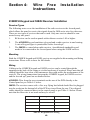
6128RFH Keypad and 5882H Receiver Installation .......................................................... 49
Receiver Types ..................................................................................................................... 49
Mounting ............................................................................................................................... 49
Wiring .................................................................................................................................... 49
Set-up .................................................................................................................................... 50
6128RFH Keypad .................................................................................................................. 50
5882H Receiver ..................................................................................................................... 50
Wire Free Programming ...................................................................................................... 50
Programming wire free zones ................................................................................................ 50
Deleting a wire free zone ....................................................................................................... 51
Adding Keyfobs for setting/unsetting ..................................................................................... 51
Standard Mode ...................................................................................................................... 51
High Security Mode (6128RFH only) ..................................................................................... 52
Deleting Keyfobs ................................................................................................................... 52
6128RFH Keypad Operation ................................................................................................. 52
Hot Keys ................................................................................................................................ 52
Wire Free Installation Hints and Tips ................................................................................ 53
Site Surveying ..................................................................................................................... 53
Walk Test .............................................................................................................................. 53
Section 5: Operating The Accord .............................................................. 55
Setting and Unsetting the System ..................................................................................... 55
Full Set 1 ( ) ........................................................................................................................ 55
Part Set 2 ( ) ....................................................................................................................... 55
Night Set 3 ( ) ..................................................................................................................... 56
Unsetting [4] .......................................................................................................................... 56
Engineer Setting and Unsetting ............................................................................................. 56
Testing the System 5 ( ) ...................................................................................................... 56
Omit Zone 6 (
) ............................................................................................................... 57
Changing Codes 8 (
) ...................................................................................................... 57
Enabling/Disabling the Chime Function 9 ( ) .................................................................... 58
Viewing the Event Log from a System Keypad 0 ................................................................... 59
Programming the Time and Date .......................................................................................... 60
Hot Keys ................................................................................................................................ 60
VI
Section 6: Systems Indications and What they Mean .............................. 61
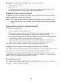
Section 7: Handing the System Over to the User ..................................... 63
Fill In the User Instructions! ............................................................................................... 63
Appendix A: Specifications ............................................................................................... 63
Panel Specification ................................................................................................................ 63
Remote Keypad Specification ............................................................................................... 64
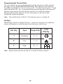
Appendix B: Connecting a Printer to the System ............................................................ 64
Installing a Printer .................................................................................................................. 64
Appendix C : Bell-Box Connections .................................................................................. 65
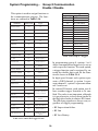
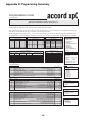
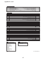
Appendix D: Programming Summary ................................................................................ 66
ADEMCO MICROTECH LIMITED WARRANTY ................................................................ 68
VII
VIII
Section 1:
Wiring Regulations and
Safety Compliance
General Information
It is essential that this product is installed correctly, in particular with respect to a
persons safety and connection to the mains electricity supply. This product is not
suitable for installation, maintenance or connection by the user. A competent, qualified installer, with for example BS5750 or NACOSS approval, must carry out installation and maintenance.
Compliance
The Accord xpC is compatible with the relevant parts of the following standards:
• BS 4737
• EN 60950
• CTR 21
• CE Standards (EN 50130-4)
• EN 41003
It is a condition of the product’s approval that the installation complies with the
following:
Siting
The control panel enclosure must be sited indoors in a secure area where it cannot be
readily interfered with. There must be adequate ventilation, ample light and easy
access for servicing and maintenance. It is not suitable for siting externally or in harsh
environments where it could be subject to high humidity, extremes of temperature,
chemical atmospheres, high dust levels, or in a position where it may be subject to
being dripped on, or splashed by, water or other fluids.
The enclosure base must be securely fixed to a vertical, smooth, solid surface that is a
part of the fabric of the building. The position chosen must allow the cabinet door to
be removed and allow unhindered access for installation and maintenance.
Ventilation
While the control panel has been designed so that no part attains an unsafe temperature it is important that adequate ventilation is provided around the cabinet, therefore
the cabinet should not be positioned close to heat-radiating equipment or other sources
of heat.
1
Cabling
The panel has high voltage barriers between the a.c. mains supply and the alarm
wiring terminals. It is essential that these barriers are maintained in the way the cables
enter the cabinet, are routed inside the cabinet, and are routed externally.
Additional holes must not be cut in the enclosure, rear entry points are provided for
cables. Alarm system cables must be neatly trimmed and not allowed to loop inside
the cabinet .
Cables external to the cabinet must be either firmly affixed to the fabric of the building using suitable clips or saddles, or mechanically protected in conduit or trunking. It
must not be possible to put strain on the wiring within the control cabinet by pulling
on cabling external to the cabinet.
It must not be possible to push a finger or similar size object or instrument into any
hole or cable entry point.
Mains Supply Connections
The connection to the a.c. mains supply must be made by a competent, qualified
person, for example NICEIC approved, in accordance with the current IEE and local
supply regulations.
Warning:
A means of isolation from the mains supply must be provided
within two metres of the control panel. Where live and neutral
supplies can be identified, a fused spur with a 3A fuse, must
be fitted on the livecircuit. Where live and neutral circuits cannot
be reliably identified, 3A fuses must be fitted to both circuits.
Where a flexible cable is connected to the control having cores coloured brown and
blue it is important to connect the wires to the mains terminal block as follows:
• Blue (Neutral) – connect to terminal N
• Brown (Live) – connect to terminal L
Where a non-flexible cable is connected to the control having cores coloured red with
black sleeves, it is important to connect the wires according to the following code:
• Black (Neutral) – connect to terminal N
• Red (Live) – connect to terminal L
Note: No connections should be made to the Earth terminal (marked E) or on the
mains terminal block.
The insulation of each conductor must be prepared and connected such that no part of
the bare conductor is visible or protruding outside the terminal block. In the case of
standard conductors, all the strands must be twisted together and firmly clamped in the
mains terminal block.
The outer covering insulation must be clamped under the cable clamp. It is important
that this cable enters the control panel enclosure through the mains entry hole under
the mains terminal block, is not looped within the control panel enclosure and does not
run close to other system cables inside or external to the enclosure.
2
The control panel enclosure must not be opened before isolating the mains supply.
The cover must be securely fitted in normal use.
Mains Cable Type
The conductors of the mains supply cable must have a minimum cross-sectional area
of 0.75 mm and the insulating material on each conductor must be a minimum of 0.4
mm thick Polyvinyl Chloride (pvc). Flexible cables must conform to the requirements
of BS6500 and IEC Publication 227. Non-flexible electrical installation cables must
conform to BS6004.
Telecoms Approvals
Connection to the PSTN
The Telecommunications Network Voltage (TNV) port (terminals A and B on TB5)
must be permanently connected (hard-wired) to the PSTN via a BT master socket. If
the BT master socket is a newer type (NTE5/CTE5), the connection can be carried out by
the installation engineer. If the BT master socket is not an NTE5/CTE5, then the connection must be made by the network operator. The Accord control panel should be
connected to the BT master socket using cable suitable for connection to 2.8 mm
diameter screw terminals.
Note: Prevent exposure to potentially lethal voltages from the PSTN by replacing the
Control Panel cover when connection to the BT master socket is complete.
Interconnecting circuit equipment should comply with the requirements of 4.2 of
EN41003 for TNV (Telephone Network Voltage) circuits and 2.3 of EN60950 of
SELV (Safety Extra Low Voltage) circuits. Compliance must continue after making
connections between circuits.
Approvals
The Accord xpC is approved for connection to direct lines of the PSTN and PBX
exchanges (with or without secondary proceed indication).
It should be noted that the Accord xpC is not suitable as an extension to a payphone.
The Accord xpC has been approved for the use of the following facilities:
•
•
•
•
•
•
•
Auto-dialling.
Auto-answering.
Auto-clearing.
Modem communications.
Series connection.
Operation with Call Process Monitor (CPM) tone recognition.
Multiple repeat attempts.
Any other usage invalidates the approval of the Accord xpC if, as a result, it then
ceases to comply with standards against which approval was granted.
3
Approval of the Accord xpC is also invalidated if it is used with internal software or
subjected to any hardware modification not authorised by BABT.
Public Switched Telephone Network (PSTN) Approval
The equipment has been approved to {Council Decision 98/482/EC} for Pan European single terminal connection to the Public Switched Telephone Network
(PSTN). However due to differences between the individual PSTNs provided in
different countries the approval does not, of itself, give an unconditional assurance of
successful operation on every PSTN network termination point.
In the event of problems contact the equipment supplier in the first instance.
The Accord xpC is designed to interwork with the following networks:
Austria
France
Italy
Norway
Switzerland
Belgium
Greece
Liechtenstein
Portugal
United Kingdom
Denmark
Iceland
Luxembourg
Spain
* Germany
Finland
Ireland
The Netherlands
Sweden
Note: Contact the equipment supplier before using the Accord xpC on any network
not listed.
Private Branch Exchange (PBX) Approval
The Accord xpC is only approved for use with BABT approved pbxs. The correct
operation of the Accord xpC can not be guaranteed under all possible conditions of
connection to compatible pbxs.
REN and SEN Numbers
• The REN of the Accord xpC is one (1).
• The SEN of the Accord xpC is 0.3.
• Nominal series resistance is 90 milli-ohms.
• Nominal insertion loss is 0.1 dB.
Note: Difficulties may be experienced when making calls from other apparatus if the
total sen value approaches one or the total series resistance 50 ohms.
Zone Cable Type
Zone and detector cable should be standard alarm cable.
* May have interworking difficulties.
4
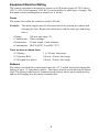
Equipment Electrical Rating
The control equipment is designed to operate on a UK mains supply of 230 Volts a.c.
(230 V ±10%) at a frequency of 50 Hz. It is not suitable for other types of supply. The
maximum current consumption in normal use is 80 mA.
Fuses
The mains fuse within the cabinet is rated at 200 mA.
Example: The mains supply must be disconnected before opening the cabinet and
changing the fuse. Replace the mains fuse with the same type and rating,
that is:
•
•
•
•
Rating:
Construction:
Dimensions:
Conformance:
200 mA anti-surge (T).
Glass cartridge.
20 mm length, 5 mm diameter.
BS EN 60127-2 and IEC127-2.
There are three on board fuses:
• F1 Battery:
• F2 Speaker/Bell:
• F3 Keypad/Aux power:
1 A, 20 mm, Anti-surge.
500 mA, 20 mm, Anti-surge.
500 mA, 20 mm, Anti-surge.
Batteries
The battery used with the control panel must be a 12 V sealed lead-acid rechargeable
battery of up to 7.2 Amp-hour capacity. The battery must be positioned on the battery
shelf. The battery leads must be connected to the battery observing terminal polarity
and not left hanging near the mains terminal block.
5
6
Section 2:
Installing the Accord XPC
Ancillaries Pack
The Accord xpC control panel comes with an ancillaries pack. It contains ten zone
links, a cable clamp (with two self tapping screws), two M4×20 mm lid screws,
battery connector leads and 16, 1K resistors.
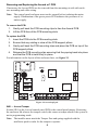
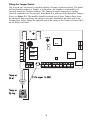
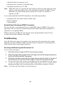
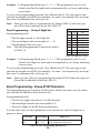
Initial Mounting
Use the keyhole slot in the enclosure base to position the control panel enclosure.
Three mounting screws (not provided) are required to mount the enclosure base. Fix
one of the screws into the mounting surface, this will be used for the top, keyhole
mounting hole. Hang the enclosure base onto the mounting screw ensuring that the
screw sits in the narrow portion of the keyhole.
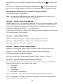
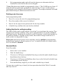
All cables should be brought into the enclosure base via the cable entry points shown
in figure 2.1. There are six cable entry holes for the entry of alarm cables. There is
one a.c. mains cable entry point located below the mains terminal block.
Lid Hinge
Lid Hinge
Recess
Recess
Keyhole
Transformer Output
Mounting
Lead to PCB
Slot
PCB
Terminal Marked AC
Cable Entry
Mains Terminal Block
Points
with 200mA fuse.
See Connecting
PCB Clip
PCB Clip
Power to the System
Secure Mains
Cable After Feeding
Knockout Tamper
Through Entry Point
Posts
Mounting
Mounting
Hole
Hole
Lid Screw
Transformer
User Instruction
Lid Screw
Terminal
Output
retaining Clip
Terminal
Figure 2.1 Accord XPC Enclosure Layout
Note: Leave about 60 mm above the control panel enclosure to enable the enclosure
lid to move on its hinges for removal and replacement.
7
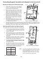
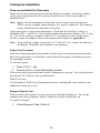
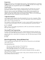
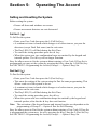
Removing and Replacing the Accord XPC PCB
If necessary the Accord PCB can be removed from the mountings to aid with enclosure mounting and cable wiring.
Note: The control panel enclosure must not be opened before isolating the mains
supply. Illumination of the green power LED indicates the presence of a.c.
mains supply.
To remove the PCB:
1.
2.
Gently pull back the PCB mounting clips to free the Accord PCB.
Lift the PCB free of the PCB mounting slots.
To replace the PCB:
1.
2.
3.
Insert the PCB into the PCB mounting slots.
Ensure that any cabling is clear of the PCB support pillars.
Gently pull back the PCB mounting clips and place the PCB on top of the
PCB support pillars.
4. Release the PCB mounting clips ensuring that they spring back into place
and that the PCB is held firmly in place.
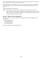
For information on the layout of the enclosure base, see figure 2.1.
VADJ
EE Volume
PHONE
+
1
AC
IC12
4
+
BATTERY
AB
AC
BATT
0.5 Amp
1
1 Amp
T1
S1
1
+
_
BELL
STRB
5
AUX KPAD TRIG LS
0.5 Amp
BELL
LED
AUX
X1
5
_R _
BTMP
SW 1
RL1
2
7
6
8
3
5
4
ZONE 1
TAMP ZONE ZONE ZONE ZONE ZONE ZONE ZONE ZONE
Figure 2.2 Accord xpC pcb
SW1 — Accord Tamper
Switch SW1 on the Accord control panel PCB is the control panel tamper. Removing
the enclosure lid releases the tamper switch; this causes a tamper alarm if the system is
not in programming mode.
Note: The installer must attach the Tamper Post and spring supplied with the
ancilleries pack in order for the tamper to operate.
8
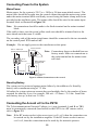
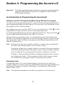
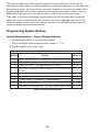
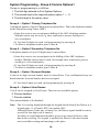
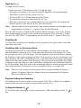
Fitting the Tamper Switch
The Accord xpC enclosure is supplied without a Tamper Actuator in place. The panel
will not function without a Tamper, it is therefore, the installer’s responsibility to
correctly attach the Tamper Actuator. The Tamper Actuator consists of a spring,
which is supplied in the Accord xpC Installation Kit, and one of the Knockout Tamper
Posts, see figure 2.1. The installer should knockout one of these Tamper Posts from
the enclosure base and ensure the spring is securely attached to the short end of the
Tamper Post, before fitting the opposite end of the spring to the Tamper Switch (SW1)
on the PCB (see below).
VADJ
EE Volume
4
+
BATTERY
AB
IC12
AC
BATT
0.5 Amp
1
1 Amp
T1
S1
+
_
BELL
STRB
5
AUX KPAD TRIG LS
0.5 Amp
BELL
LED
AUX
X1
1
Tamper
Post
PHONE
+
1
AC
5
_R _
BTMP
SW 1
RL1
2
7
6
8
3
5
4
ZONE 1
TAMP ZONE ZONE ZONE ZONE ZONE ZONE ZONE ZONE
Fit Tamper to SW1
Tamper
Spring
9
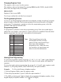
Connecting Keypads, Sounders and a Speaker to the Accord XPC
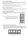
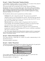
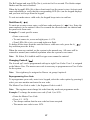
Mounting and Wiring the LED Remote Keypad
1.
Press down the two base clips recessed
on top of the keypad while gently pulling
the two halves of the case apart.
2.
Route the wiring from the Control Panel
through the Cable Entry Hole on the back
case. Use Knockout Holes A or B if
alternative routes are necessary. Tip: Use
a knife to help dislodge knockouts.
Knockout
Hole A
Mounting Holes
Base Clip
Cable Entry
Hole
Base Clip
Tamper Tab
Screw Hole
3.
Securely mount the back case to a wall or
electrical box via the mounting holes.
Ensure The Tamper Tab is securely
screwed down.
4.
The remote keypad PCB should be wired
to the control panel PCB as outlined in Table
2.1 LED/Icon Keypad Wiring.
5.
Re-attach the keypad front to the back case by inserting the hinges on the keypad front into
the hinge retainers on the bottom of the keypad back case. Gently apply pressure to the
keypad front until the two retaining tabs click firmly into place.
Hinge Slot
Mounting Holes
Knockout
Hole B
Hinge Slot
Fig 2.3 Accord xpC LED Keypad
Mounting and Wiring the Icon Remote Keypad
To mount and wire the Accord xpC Icon keypad:
1.
Knockout
Knockout
Knoc
out
Loosen the retained fastening screw on the bottom
of the keypad. Gently pull the front and back
keypad casing apart.
2.
Route the wiring from the control panel through
any of the five knockout holes on the back case
of the keypad. Tip: Use a knife to help dislodge
knockouts.
3.
Securely mount the back case to a wall or
electrical box via the mounting holes. Ensure The
Tamper Tab is securely screwed down.
4.
The remote keypad PCB should be wired to the
control panel PCB as outlined in Table 2.1 LED/
Icon Keypad Wiring.
5.
Re-attach the keypad front to the back case,
aligning the hinges on the top. Gently apply
pressure to the keypad front and tighten the
retained fastening screw on the bottom.
P an el
K eyp ad
AUX+
+ve
AUX–
–ve
K'PAD/DO
kpad
Note:
Table 2.1 LED/Icon Keypad Wiring
10
EV8-2000
EV8-2000
Mounting
Hole
>PC+ABS FR<
FR<
Knockout
Holes
Knockout
Tamper Tab
Screw Hole
Knock
Knock
Knockout
Hole
Retained
Fastening Screw
Mounting
Hole
Fig 2.4 Accord xpC Icon Keypad
Up to four keypads can be connected to the
system. Keypads can be wired to the control
panel independently, in series, or in a star
configuration. Both LED and Icon keypads
can be connected to the same panel.
Connecting the External Sounders
Connections for Self Actuating Bells and Bell/Siren combinations should be made as
outlined in table 2.2 and table 2.3.
Connections
for SAB
Connection for
Bell/Siren only
P an el
Bell
P an el
BELL +
Positive Supply/Hold Off
BELL +
Bell & Strobe Positive
BELL –
Trip/Signal Negative
BELL -
Bell Negative
Tamper SW Common
Bell
BELL TAMP –
Negative Supply/Hold–Off
BELL TAMP -
BELL TAMP – R
Negative Tamper Return
BELL TAMP - R
Tamper SW N/C
STRB
Strobe Negative Signal
STRB
Strobe Negative
Table 2.2 Connections for SABs
Table 2.3 Connections for Bell/Siren only
Wiring the Loudspeaker
A 16 Ω Loudspeaker may be connected between the LS terminal and the Aux +
terminal.
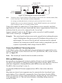
Wiring the Zones
The zones on the Accord xpC can function in one of three modes; Normal Closed,
Double Balanced and U.S. End of Line. Zone wiring for the three modes are illustrated below. The mode of operation for the zones is programmed from Group 5 —
Option 9 Zone Configuration.
It is strongly recommended that the maximum cable run on each zone is 100 m.
Figure 2.5 Zone Wiring for Normal Closed
ALARM TAMP
1K
1K
Figure 2.6 Zone Wiring for Double Balanced Zones
1K
Figure 2.7 Zone Wiring for US EOL Zones
Zone Links
The eight zones, the zone tamper and the bell tamper circuits can be shorted using the
Zone Links provided in the ancillaries pack. It is strongly recommended that this be
done if any of the circuits are not to be used. If Double Balanced or U.S. End of Line,
fit a 1K resistor across the zone and not the shorting link.
11
Connecting Power to the System
Mains Power
Mains power for the system is 230 V a.c. 50 Hz (a 24-hour unswitched source). The
mains cable should be brought into the control cabinet through the mains entry point
under the mains terminal block and firmly secured using the mains clamp and screws
provided in the ancillaries pack. The mains cable should be wired to the mains input
terminal block as illustrated in figure 2.8.
Note: No connections should be made to the Earth terminal on the mains terminal
block.
If the cable is three core the green/yellow earth core should be trimmed back to the
outer sheath such that none is visible.
The secondary side of the mains transformer should be connected to the two terminals
on the control panel PCB marked AC.
Example: Do not apply power to the transformer at this point.
Accord XPC PCB
AC
GND
From a.c. mains input
(entering below terminal block)
TB6
200 mA
mains fuse
Note: Connections shown as dashed lines are
factory made. Make no connections to
the earth terminal on the mains terminal block.
Mains Transformer
Secondary Side
Brown Wire
Blue Wire
Mains Transformer
Primary Side
Figure 2.8 Mains Connections to the Accord
Stand-by Battery
The system can be protected against mains failure by the addition of a Stand-by
battery with a maximum rating of 7.2 Ahr.
Calculate the system quiescent current draw and multiply this by the number of hours
required for stand-by cover, for example, 200 mA × 12 hours = 2.4 Ahr. Install the
next battery size up, in this case 2.8 Ahr.
Connecting the Accord XPC to the PSTN
The Telecommunications Network Voltage (TNV) port (terminals A and B on TB5)
must be permanently connected (hard-wired) to the PSTN via a BT master socket,
refer to figure 2.9.
Note: If the BT master socket is the newer type (NTE5/CTE5), then the connection can
be carried out by the installation engineer. If the BT master socket is not an
NTE5/CTE5, then the connection must be made by the network operator.
12
Accord XPC PCB
A B PHONE
BT Master socket (NTE5/CTE5).
BT Master socket (NTE5/CTE5).
TB5
Incoming
PSTN Line
2
5
2
5
Figure 2.9. Connecting the Accord XPC to the PSTN
Note:
Terminals 2 and 5 on the BT Master Socket should be hard-wired to the A and B terminals (TB5)
on the Accord xpC. This connection is polarity independent.
It is strongly recommended that the Accord xpC panel is the only device on the line.
If another device is to be connected to the line, connect PHONE terminals on the Accord xpC
PCB to terminals 2 and 5 on a second BT Master Socket
Using cable suitable for connection to 2.8 mm diameter screw terminals, strip back
approximately 20 mm of the outer sheath and then remove approximately 4 mm of the
insulation from the wires to be connected to the Accord xpC.
Connect terminals 2 and 5 on the BT Master socket across the A and B terminals
(TB5) on the Accord xpC, see figure 2.9.
Example: The control panel enclosure must not be opened before isolating the mains
supply. Illumination of the green power LED indicates the presence of a.c.
mains supply. The cover of the Accord xpC enclosure must be replaced
whenever any connection to the BT master socket is completed to prevent
exposure to potentially lethal voltages from the PSTN.
Connecting Additional Telecom Apparatus
A BT Master socket, allowing additional telecom apparatus to be connected in series
with the Accord xpC can be connected to the TNV port PHONE (TB5) on the Accord
xpC, see figure 2.9.
Note: The Accord xpC should be the first module on the line.
REN and SEN Numbers
It is possible to simultaneously connect a number of items to one line of the PSTN.
The limit is determined by summing the Ringer Equivalence Number (REN) shown on
each item of apparatus, ensuring that the sum of RENs is not more than four.
The REN of the Accord xpC is one (1).
Assume that all British Telecom equipment has a REN of one unless otherwise
marked.
More than one item of series apparatus may be connected to the Accord xpC ports
marked phone. This is limited by summing the Series Equivalence Number (SEN)
shown on each item of series connected apparatus, ensuring that the sum of the SENs
is not more than one (1). The total series resistance, including cabling, must not
exceed 50 Ohms.
13
• The SEN of the Accord xpC is 0.3.
• Nominal series resistance is 90 milli-ohms.
• Nominal insertion loss is 0.1 dB.
Note: Difficulties may be experienced when making calls from other apparatus if the
total SEN value approaches one or the total series resistance 50 ohms. If such
difficulties are experienced, please consult the Accord XPC installer or
supplier, not BT.
It is recommended that the PSTN should have the following facilities:
• Outgoing calls only (when used as dialler only).
• Direct exchange.
• Tone dialling.
Private Branch Exchange (PBX) Connection
The Accord xpC is only approved for use with BABT approved PBXs. The correct
operation of the Accord XPC can not be guaranteed under all possible conditions of
connection to compatible PBXs.
When connected to a PBX, the Accord xpC can be programmed to pause for two
seconds, between the dialling of the digits.
Final Mounting
Once all cable entries have been made to the enclosure and connected to the control
panel the enclosure should be firmly mounted in place using the two mounting holes
at the bottom of the control panel enclosure.
Securing and Removing the Enclosure Lid
To secure the lid in place:
1.
2.
3.
4.
o
Hold the lid at an angle of 90 to the enclosure base.
Place the eight (two groups of four) lid hinges into the lid hinge recesses on
the lip of the Accord xpC enclosure.
Swing the lid down such that the hinges swing into the holes in the top of
the enclosure rim and the lid fits snugly on top of the enclosure base.
Fix the lid in place by inserting and tightening the two M4×20 mm pan head
screws provided, into the screw holes in the bottom corners of the lid.
Note: To remove the lid, simply reverse the process.
14
Testing the Installation
Power-up and Initial Test Procedure
When the Accord control panel has been installed in accordance with the preceding
safety and wiring instructions the system should be tested. The test procedure is
outlined below.
Note: Before the test commences all auxiliary devices such as powered sensors
(PIRs), remote keypads, alarm sounders, etc, must be connected. The stand-by
battery should not be connected at this point.
Apply input power to the mains transformer. Check that the Auxiliary Voltage at
terminals AUX + and AUX – on the main terminal strip measures between 13.5 V and
14 V d.c. If the auxiliary voltage is under 13.5 V, too much current is being drawn.
For the current consumption of the control panel and keypads see Appendix A.
Note: If the auxiliary voltage is between 13.5 V and 14 V d.c., connect the battery to
the Battery Terminals, observing the correct polarity.
Further Test Procedure
Once the control panel has been installed, and the power up and initial test procedure
have been performed, it is advisable to check that the keypad(s) and ancillary devices
are operating correctly.
To test the keypad:
1. Press 1234 1 – Set.
2. Press Ö (Exit) – Panel Exits setting routine.
This ensures the keypad and control panel communicate correctly. Test each keypad in
this manner. See Section 4 for test information.
Walk Test Zones:
It is advisable to Walk Test all programmed zones, including RF zones and any zone
added after initial Power-Up.
Engineer Digicom Test:
This test allows the engineer to send a test report through the digicom. Two beeps
confirm entry of key sequence whilst a further two beeps confirm kiss off.
To send Test Report:
1.
Press Engineer Code, # then 5.
15
16
Section 3: Programming the Accord XPC
Important: The following programming instructions integrate programming details
using both LED and Icon keypads. Icon keypad (in brackets) follow
LED keypad indications.
An Introduction to Programming the Accord xpC
Getting In and Out of Programming Mode Using LED and Icon keypads.
All zone and system programming must be carried out from the Programming Mode. To
enter Programming Mode enter the Engineer Code, press the # key and then the Ö key.
The Engineer Code is 9090 by default.
The keypad beeps twice, the Day LED (•) goes out and the Power LED (
keypad flashes to indicate that the system is in programming mode.
) on the
To exit Programming Mode press the # key followed by the Ö key. The power LED (
on the keypad stops flashing and the Day LED (•) activates.
)
During engineer programming mode, no communication to the central station will
take place. To perform an engineer reset enter the four digit engineer code (no need to
enter programme mode). Entering the programme mode during communication will
abort the communication.
Note: Pressing the Ö and # keys together within five seconds of power up defaults
the master code and the engineer code to factory settings.
Pressing the Ö and # keys together within five seconds of leaving the engineer
mode also defaults the master and engineer codes to factory settings. Pressing
any key within the five second period extend it for a further five seconds.
If Group 5 - Option 4 (Hotkey Enable) is enabled, pressing Ö and # activates
the keypad panic facility . The keypad panic facility will not operate within
five seconds of leaving engineer mode or powering up the system.
Defaulting Codes
To default the Master User Code and the Engineer Code press the Ö and # keys
together within five seconds of power up. Hold both keys down for approximately two
seconds until two beeps are emitted. The Engineer Code defaults to 9090 and the
Master Code to 1234.
Note: For important information on Ö and # key operation see the note above.
17
Changing Engineer Code
The engineer code is user 0 on the system.
The engineer code can be changed by entering 9090, then 8 (CODE), then 0 (LOG)
then a new four digit code; for example:
9090 8 0 5678
Engineer Code is now 5678
Two beeps confirm the code has been accepted.
The Programming Format
An easy to use Programming Format has been adopted, to make Accord xpC programming as simple as possible. Each system parameter has been allocated to a Programming group. To programme a parameter select the programming group, select the
parameter and enter the desired value.
Programming Fields
To programme a parameter select the programming group. Enter the second digit to
choose the zone number, zone option or system option to be modified. Enter the third
digit to programme the zone type, zone option or system option.
K ey
1
Name
Full Set options
2
Part Set Options
3
Night Set options
4
System Options 1
5
System Options 2
6
Comms Options 1
7
Comms Options 2
8
Comms Triggers
9
System Options 3
0
System Options 3
#1
RF Zones
#2
Soak Test
#6
Confirm Options
Note: If the keypad beeps twice the
information has been correctly
entered. If the control panel beeps
three times after making a
programme entry, either the entry
was invalid or too much time was
taken to enter the information.
Table 3.1 Programming Groups
Viewing Field Programming
To view the programme options in groups 1, 2, #2, 3, 4, 5, #6, 7, and 9; enter Engineer
mode and enter the group number then 00. The value for each option will display in
sequence.
To view the single option programming for groups #1, 6, 8 and 0, enter engineer mode
followed by the group number, then 0 followed by the option number.
Example:
To View the Primary telephone number:
1. If not in Engineer Mode, enter the engineer code.
2. Enter the group number 6, press 0, then the option number 1.
3. The LEDs on the keypad, light to display the programmed telephone number, (Icon
keypad displays telephone number as a sequence of digits).
18
Programming Groups 1, 2 and 3 (Zone Programming For Full,
Part and Night Set)
Programming Groups one to three are used to programme the eight zones for each of
the three setting modes: Full, Part and Night Set. This allows zones to be isolated or
assigned different functions for each of the three setting conditions.
The available zone types are:
0.
1.
2.
3.
4.
Not Used
Final Exit
Key switch
Alarm
Walk Through
5.
6.
7.
8.
9.
24 hr tamper
PA silent
PA audible
Push-to-set
Fire
Zone Programming — Group 1 Full Set
In programming mode:
Full Set
Group
• The first digit entered is 1 for Full Set.
• The second digit is the zone number 1 — 8.
• The third digit is the zone type, see table 3.2.
Zone
No
Default Zone
Type
1
1
(1)
1
2
(4)
1
3
(3)
1
4
(3)
1
5
(3)
1
6
(3)
1
7
(3)
1
8
(3)
Table 3.2 Full Set Zones
Example: In Programming Mode press 1 + 2 + 3. This programmes Zone 2 as an
Alarm in the Full Set mode and is accompanied by two beeps, indicating a
correct entry.
To view the programming: press the 1 key followed by 00. The zone type is indicated
on the keypad zone LEDs (Icon display) for zone 1 (accompanied by one beep), then
zone 2 (accompanied by one beep), etc.
Note: Zone type nine (Fire) is represented by the Tamper LED (9) and zone type
zero (Not used) is indicated by the Day LED (•).
Zone Programming — Group 2 Part Set
In programming mode:
• The first digit entered is 2 for Part Set.
• The second digit is the zone number 1 — 8.
• The third digit is the zone type.
Part Set
Zone
No
Default Zone
Type
2
1
(1)
2
2
(4)
2
3
(3)
2
4
(3)
2
5
(3)
2
6
(3)
2
7
(3)
2
8
(3)
Group
Table 3.3 Part Set Zones
19
Example: In Programming Mode press 2 + 2 + 3. This programmes zone 2 as an
Alarm in the Part Set mode and is accompanied by two beeps, indicating a
correct entry.
To review the programming: press the 2 key followed by 00. The zone type is indicated on the keypad zone LEDs (Icon display) for zone 1 (accompanied by one beep),
then zone 2 (accompanied by one beep), etc.
Note: Zone type nine (Fire) is represented by the Tamper LED (9) and zone type
zero (Not used) is indicated by the Day LED (•).
Night Set
Zone Programming — Group 3 Night Set
In programming mode:
Zone
No
Default Zone
Type
3
1
(1)
3
2
(1)
3
3
(3)
3
4
(3)
3
5
(3)
3
6
(3)
3
7
(3)
3
8
(3)
Group
• The first digit entered is 3 for Night Set.
• The second digit is the zone number (1 — 8).
• The third digit is the zone type.
Note: The default programming is shown in brackets
in Table 3.4
Table 3.4 Night Set Zones
Example: In Programming Mode press 3 + 2 + 3. This programmes zone 2 as an
Alarm in the Night Set mode and is accompanied by two beeps, indicating
a correct entry.
To review the programming: press the 3 key followed by 00. The zone type is indicated on the keypad zone LEDs (Icon display) for zone 1 (accompanied by one beep),
then zone 2 (accompanied by one beep), etc.
Note: Zone type nine (Fire) is represented by the tamper LED (9) and zone type zero
(Not used) is indicated by the Day LED (•).
Zone Programming - Group #1 RF Detectors
This programming group is used to tell the system which zones have wire-free detectors and what the details of those detectors are.
In programming mode:
• The first two digits entered are #1 for RF detectors
• The third digit entered is the zone number 1-8
• The next 9 digits are the RF detector parameters.
For each zone, there are three parameters to be entered, as a total of 9 digits in sequence as shown.
First Digit
Supervision (0
or 1)
Second Digit
Loop number
used (1 or 2)
Digits 3 to 9
The 7 digit serial number of the detector
being programmed to this zone
Table 3.5 Zone Programming RF Detectors
20
Supervision
Selects if the device is to be monitored for presence. This should always be selected as
1 (ON) unless the zone is a portable panic button that may be taken out of range of the
receiver. In this case, program the supervision as 0 (OFF).
Loop Number
Selects which loop of the transmitter is being used for the selected zone. For most
transmitters this is 1 as there is only one detection loop (zone) in the transmitter.
However, devices such as the 5816H have 2 loops which can be assigned to two
separate zones on the panel. On the 5816H, the wiring terminals for an external
contact are loop one, and the built in reed switch is loop 2. Please see the installation
guide supplied with the transmitter for more information.
7 Digit Serial Number
is the unique number printed on the label attached to the wire free transmitter. When
entered, this number tells the panel to look at the appropriate loop on this transmitter
and no other, for this particular zone.
For example, to tell the panel that zone 3 is to be a supervised RF zone using loop 1 on
a detector with serial number 0236187, the following sequence should be entered:
#1 3 1 1 0236187.
When a zone is successfully programmed as an RF zone, the hardwire terminals for
that zone will be ignored.
Clearing RF Zone Programming
To remove RF programming from a zone, program the RF parameters for that zone
with the supervision and loop parameters as 0. For example, to clear the RF programming for zone above, and return it to a hardwire zone, the following sequence should
be entered:
#1 3 0 0.
Zone Programming - Group #2 Soak Test
This programming group enables the 14 day soak test function for each individual
zone on the system.
In programming mode:
• The first two digits entered are #2 for Soak Test
• The third digit entered is the zone number 1 - 8
• The fourth digit entered is 0 or 1 to select soak test on that zone.
Selecting 0 for this option switches off the soak test function for that zone and the
zone will behave normally.
Selecting 1 for this option switches on the 14 day soak test function for that zone. The
zone will then behave as follows:
21
The zone on soak test will be monitored by the system at all times. If the zone is
activated at a time when it would normally have caused an alarm (e.g. an intruder zone
during the set state), no alarm will be generated. Instead, a soak test activation will be
logged against that zone and the soak test timer will be returned to 14 days. Also an
indication of the activated zone will be shown at the keypad in the unset state.
If the zone is not activated during a period when it would normally have caused an
alarm, the soak test timer will be decreased by one day at midnight each day. If the
soak test counter reaches zero, the soak test for that zone will end and the zone will
return to normal operation automatically.
Programming System Options
System Programming — Group 4 System Options
• The first digit entered is 4 for System Options.
• The second digit is the required system option (1 — 9).
• The third digit is the option value.
SYSTEM OPTIONS
GROUP
OPTION
DEFAULT
4
1=Exit Time (0=Final Contact, 1–9=Exit Time ×10 s).
(3)
4
2=Entry Time (1–9=Entry Time × 10 s).
(3)
4
3=Bell Cut- off Time — See Table 3.6 Bell Cut- off Times.
(8)
4
4=Part Set Exit Warning (0=Silent, 1=Keypad, 2=Keypad and Internal
Sounders).
(0)
4
5=External Bells and Strobe in Part Set (0=No, 1=Yes).
(1)
4
6=External Bells and Strobe in Night Set (0=No, 1=Yes).
(1)
4
7=Trigger Output — See Option 7 — Trigger Outputs.
(3)
4
8=Easy Set (0=No, 1=Yes)
(0)
4
9=Prevent Set with (0=Mains fail, 1=Low Batt, 2=Mains Fail/Low Batt)
(0)
Table 3.6 Group 4 System Options
22
Group 4 — Option 1 Exit Time
This is the amount of time that the user has to exit the premises after initiating a Full
Set procedure. Entering 411 will set the Exit Time to 10 seconds, 412 = 20 seconds,
413 = 30 seconds, to 419 = 90 seconds.
If Final Contact is required enter 410. The system will only set when a Final Exit zone
is activated after the exit timer has started (infinite exit time).
Note: Exit Times for Part Set and Night Set are fixed at 30 seconds.
Group 4 — Option 2 Entry Time
This is the period the user has to enter the premises and unset the system. Entering 421
will set the Entry Time to 10 seconds, 422 = 20 seconds, to 429 = 90 seconds.
Group 4 — Option 3 Bell Cut-off Time
This is the period the sounders/bells activate after an alarm condition has occurred. To
programme the Bell Cut-off time enter 43 then number 0 — 9, see Table 3.7 Bell
Cut-off Times.
Bell Cut-off Times
0 = Continuous Bells
1 = 1 minute
Note: The system will reset when the Bell Cut-off
Time has expired . Group 7 - Option 9 programming determines the number of times a zone will
activate before it is automatically omitted.
2 = 2 minutes
3 = 3 minutes
4 = 4 minutes
5 = 5 minutes
6 = 10 minutes
7 = 15 minutes
8 = 20 minutes
9 = 30 minutes
Table 3.7 Bell Cut-off Times
Group 4 — Option 4 Part Set Exit Warning
This option allows the Part Set exit timer to be silent, audible through the keypad, or,
audible through the keypad and internal sounder. Night Set will always have a silent
exit timer but this option will affect the Night Set comfort tone (confirmation of set)
and fault warnings given at the end of the Exit Time. All possible options are shown in
the tables 3.8 – 3.10.
PART SET EXIT WARNING — 440 SILENT
EXIT TONE
FAULT
TONE
FAULT
TONE AT
END OF
EXIT TIME
COMFORT
TONE
Part Set
None
None
Keypad only Keypad only
Night Set
None
None
Keypad only Keypad only
Table 3.8 Part Set Exit Warning: 440 Silent
23
PART SET EXIT WARNING — 442 KEYPAD BUZZER AND
INTERNAL SOUNDER
PART SET EXIT WARNING — 441 KEYPAD BUZZER ONLY
EXIT TONE
FAULT
TONE
FAULT
TONE AT COMFORT
END OF
TONE
EXIT TIME
EXIT TONE
Part Set Keypad only Keypad only Keypad only Keypad only
Night Set
None
None
Keypad only Keypad only
Table 3.9 Part Set Exit Warning : 441
Buzzer Only
FAULT
TONE
FAULT
TONE AT
END OF
EXIT TIME
COMFORT
TONE
Part Set
Both
Both
Both
Both
Night Set
None
None
Both
Both
Table 3.10 Part Set Exit Warning :
442 Keypad and Sounder
Group 4 — Option 5 External Bells and Strobe in Part Set
This option determines whether the External Bell and Strobe outputs activate during
an alarm condition when the system is Part Set. During an alarm condition, External
Bell and Strobe outputs activate when enabled (1), when disabled (0) they do not.
This option defaults to 1 (enabled).
Note: Internal sounders always sound.
Group 4 — Option 6 External Bells and Strobe in Night Set
This option determines whether the External Bell and Strobe outputs activate during
an alarm condition when the system is Night Set. During an alarm condition, External
Bell and Strobe outputs activate when enabled (1), when disabled (0) they do not.
This option defaults to 1(enabled).
Note: Internal sounders always sound.
Group 4 — Option 7 Alarm Trigger Output
This option determines the operation of the Trigger output, marked TRIG on TB1, .
This option has four settings:
0.
Set (on in any set state)
1. 0 V Detector Reset
This output type is used to provide the negative supply to devices such as sensors. The
0 V supply is removed for five seconds when the setting procedure is initiated to
ensure devices are reset before the system sets. After an alarm activation, the 0 V will
be removed when the system is reset to clear any latched conditions.
2. Set Latch Positive
This output type is used with latching PIRs. The output is set to 0 V switching to 12 V
when the first of the following occur:
• Alarm Condition.
• Entry Timer is Started.
• System is Unset.
3. Alarm
This sets the output to 12 V switching to 0 V when any of the following occur:
24
• Alarm Condition.
• Panic Alarm.
• Fire Alarm.
This output may be used to trip a transistorized relay for control of auxiliary equipment. The alarm trigger can also be inverted so that it is normally 0 V switching to 12
V, see Programming Group 5 Option 7 Trigger Output.
This option defaults to (3) Alarm.
Group 4 — Option 8 Easy Set
When enabled (1) this option allows users to (Full, Part or Night) set the system
without entering a user code.
When enabled users set the system by pressing the # key and : 1 (to Full Set), 2 (to
Part Set), or 3 (to Night Set). The same exit times as apply as with Full, Part and Night
Set. A valid user code is still required to unset the system.
This option defaults to 0 (disabled).
Group 4 — Option 9 Prevent Setting for Power Fails
This option determines which power fail conditions prevent setting of the system:
0. Mains fail.
1. Low battery.
2. Mains fail and low battery.
This option defaults to 0 (mains fail).
System Programming — Group 5 System Options
Group five programming is as follows:
1.
2.
3.
The first digit entered is 5 for System Options.
The second digit is the required system option 1 — 9.
The third digit is the option value.
SYSTEM OPTIONS
GROUP
OPTION
DEFAULT
5
1=Audible Warning of AC Loss (0=No, 1=Yes).
(0)
5
2=Supplementary Entry (0=No, 1=Yes).
(0)
5
3=Engineer Reset for Alarms.
(0=Customer, 1=Engineer, 2=Technistore, 3=Engineer or Technistore).
(0)
5
4=Hotkey Enable (0=No, 1=Yes).
(0)
5
5=Auto Omit Keypad (0=No, 1=Yes).
(0)
5
6=Bell Output (0=Neg. Applied, 1=Neg. Removed).
(0)
5
7=Trigger Output (0=Neg. Applied, 1=Neg. Removed).
(0)
5
8=Engineer Reset for Day Tampers.
(0=Customer, 1=Engineer, 2=Technistore, 3=Engineer or Technistore).
(0)
5
9=Zone Configuration (0=N/C Loop, 1=Double Balanced, 2=E.O.L.).
(0)
Table 3.11 Group 5 System Options
25
Group 5 — Option 1 Audible Warning of AC Loss
When enabled (1) an audible indication is given from the keypad piezo that an a.c.
mains failure has occurred. The loudspeaker output LS also activates. Visual indication is always given by the deactivation of the power LED on keypads (flashing
)
and at the control panel. No audible indication is given when the system is set.
This option defaults to 0 (disabled).
Note: When disabled no audible indication is given.
Group 5 — Option 2 Supplementary Entry
When disabled (0) an alarm condition occurs if the system has not been unset at the
end of the entry time.
When enabled (1) an internal only alarm occurs if the system has not been unset at the
end of the entry time (Trigger, External Bell and Strobe do not activate). The internal
alarm will run for 30 seconds. A full alarm will occur if the system has not been unset
at the end of this time.
This option defaults to 0 (disabled).
Group 5 — Option 3 System Reset for Alarm
This option determines how the system may be reset after an alarm condition:
0. Customer.
1. Engineer.
2. Technistore.
3. Engineer or Technistore.
Set to 0 (Customer): User code resets the system after alarm activations.
Set to 1 (Engineer): User code can cancel an alarm activation but the engineer code is
required to reset the system.
Set to 2 (Technistore): User code can cancel an alarm activation but a Technistore
reset number must be entered to reset the system.
Set to 3 (Engineer or Technistore): User code can cancel an alarm activation but either
the engineer code or a Technistore reset number must be entered to reset the system.
This option defaults to 0 (Customer).
Note: A system reset by the engineer for alarms does not affect Fire, PA Silent or
PA, these can be reset by a user code.
Technistore resets are overridden for set types in which communication is not
enabled, if communication is enabled at all (Group 7 – Option 6)
Group 5 — Option 4 Hotkey Enable
When enabled (set to 1) this option permits Assistance, Fire and Panic facilities to
operate via a double-push on the keypad.
26
Assistance: Press 4+6 together. Keypad displays scrolling LEDs ( ) with fast pulse
tone.
Fire: Press 7+9 together. Keypad displays scrolling LEDs ( ) with slow pulse tone .
Panic: Press Ö and # together. All LEDs (PA) illuminate and a constant tone emits.
Buttons must be held down for two seconds for Hotkey Operation.
This option defaults to 0 (disabled).
Note: For important information on Ö and # key operation see the note in “An
Introduction to Programming the Accord xpC”.
Group 5 — Option 5 Auto Omit Keypad
When enabled (set to 1) the keypad is omitted if 20 keys are pressed without a valid
code being entered, this does not include the # key. The keypad is omitted from the
system for 10 minutes and affects all keypads on the system. Keypad auto omit is
indicated by flashing zone LEDs (– –) on the keypad.
A keypad auto omit may be cancelled by operating a zone programmed as Keyswitch.
This option defaults to 0 (disabled).
Group 5 — Option 6 Bell Output
When set to 0 the Bell output is negative applied (positive removed).
When set to 1 the Bell output is negative removed (positive applied).
This option defaults to 0 (negative applied).
Group 5 — Option 7 Alarm Trigger Output
When set to 0 the Alarm Trigger output is negative applied (positive removed).
When set to 1 the Alarm Trigger is negative removed (positive applied).
This option defaults to 0 (negative applied).
Note: Only valid when Alarm trigger Output (Group 4 - Option 7) is set to 3.
Group 5 — Option 8 System Reset for Day Tampers
This option determines how the system may be reset after a tamper condition that
occurs when the panel is unset and has four modes:
0. Customer.
1. Engineer.
2. Technistore.
3. Engineer or Technistore.
Set to 0 (Customer): User code resets the system after day tamper activations.
Set to 1 (Engineer): User code can cancel a day tamper activation but the engineer
code is required to reset the system.
27
Set to 2 (Technistore): User code can cancel a day tamper activation but a Technistore
reset number must be entered to reset the system.
Set to 3 (Engineer or Technistore): User code can cancel a day tamper activation but
either the engineer code or a Technistore reset number must be entered to reset the
system.
This option defaults to 0 (customer).
Note: This option only affects Tamper conditions occurring when the system is
unset. It does not affect tamper conditions occurring when the system is in one
of the set modes; these tamper conditions are covered by menu option Group 5
– Option 3 Engineer Reset for Alarms.
Group 5 - Option 9 Zone Configuration
The zones on the Accord xpC function as Normally Closed, Double Balanced, U.S.
End of Line.
0. Normally Closed
1. Double Balanced
2. U.S. End of Line
This option defaults to (0) Normally Closed.
28
System Programming - Group 6 Comms Options1
Group six programming is as follows:
1. The first digit entered is 6 for System Options.
2. The second digit is the required system option 1 — 9.
3. The third digit is the option value.
Group 6 — Option 1 Primary Telephone No.
A telephone number of up to 20 digits must be entered here. This is the telephone number
of the Alarm Receiving Centre (ARC).
• Enter # to create a two second pause dialling of the ARC telephone number.
Multiple entries may be used, e.g. three consecutive presses would give a
six second pause.
• If less than 20 digits are used, end programming by pressing Ö.
• To delete a telephone number press # then Ö.
Group 6 — Option 2 Secondary Telephone No.
A telephone number of up to 20 digits may be entered here.
• Enter # to create a two second pause in the dialling of the ARC telephone
number. Multiple entries may be used, for example three consecutive presses
would give a six second pause.
• If less than 20 digits are used, end programming by pressing Ö.
• To delete a telephone number press # then Ö.
Group 6 — Option 3 Account Number
A four to six digit account number must be entered here. Two confirmation beeps are
heard when the Account Number has been accepted.
• If less than 6 digits are used, end programming by pressing Ö.
Group 6 — Option 4 User Duress
User 8 can be assigned as User Duress. There are two available options.
0. Duress disabled
1. Duress enabled
This option defaults to 0 (disabled).
Note: The 16 event log displayed through the keypad should classify the Duress as a
keypad panic, i.e. all zone LED’s on together (PA).
Although Duress Codes may set/unset, etc, the Duress signal should be sent as
soon as the four digit code is entered.
No audio or visual indication should be given at any time for Duress, other
than in the event log. If a keypad is omitted, the Duress Code must remain
active and allow setting and unsetting to take place.
29
Group 6 — Option 5 Downloader Telephone Number.
A Downloader Telephone Number of up to 20 digits may be entered. If less than 20
digits are used, end programming by pressing the Ö key.
This option should only be programmed if the Ademco Microtech Windows
Downloader software is to be used with the panel. The Ademco Microtech Windows
Downloader is a software programme that allows remote servicing of the Accord xpC
panel, including programme/event-log uploading and downloading. The Ademco
Microtech Windows Downloader software runs on an IBM compatible PC running
Microsoft Windows 3.0, 3.1, 95 or 98.
The Downloader software must be operated in one of three modes:
Call Back: The call is initiated from the PC. The panel answers and the PC
establishes that the correct Downloader ID is present. The panel hangs up and calls
the Downloader Telephone No. Remote servicing may begin when the PC answers
and a correct Downloader ID is confirmed.
Wait for Call: Enter a valid user code at a keypad, press the # key then 9 to
initiate dialling of the Downloader Telephone No. Remote servicing may begin
when the PC answers and a correct Downloader ID is confirmed.
Dial Site: The call is initiated from the PC. The panel answers and checks the
programmed Account No and Downloader ID. If correct, a valid link is established
and remote servicing may begin.
Note: This option cannot be used if downloader telephone number is programmed.
Access to the system via the Downloader software is subject to menu option Group 7 —
Option 8 Downloader Options.
Group 6 – Option 6 Downloader I.D. Number
This option specifies a eight digit I.D. number for panels communicating via the
Downloader Software.
This option defaults to 99999999.
Group 6 — Option 7 Ring Count
This option determines how many times the telephone line rings before the panel picks
up. The programmable range of 00 to 15 is outlined in Table 3.12.
No of Rings
00
01 – 14
15
Panel Operation
Panel never answers incoming calls.
Entry equals the number of rings before the
panel answers.
Answer machine defeat.
Table 3.12 No of Rings
If set to answer machine defeat (15) the Accord xpC only picks up the line if the
download PC dials in, hangs up after one ring then redials.
This option defaults to 14 rings (14).
30
Group 6 — Option 8 Communicator Format
The Accord xpC panel has three communicator format options:
0. Comms disabled.
1. High Speed.
2. Contact I.D.
This option defaults to 1 (High Speed).
0 = Comms Disabled
If Option 8 Communicator Format is set to 0 the panel will not dial-out. Setting
Option 8 Communicator Format to 0 (Comms Disabled) does not erase the Comms
programming. Communication can be restored with the previous programming by
selecting 1-High speed.
1 = High Speed (8 channel)
If Option 8 Communicator Format is set to 1 the panel reports using 8 channel Ademco
Fast Format (see programming group 8).
2 = Contact I.D.
The panel reports using Contact I.D when Option 8 Communicator Format is set to 2.
Contact I.D. transmits event type and event source to the monitoring station (see
Table 3.13).
Group 6 — Option 9 Central Station (ARC) Receiver Handshake
This option has three settings:
0. UK.
1. Belgium.
2. Paris.
This option defaults to 0 (UK).
31
System Programming - Group #6 Confirm Options (DD243)
These options allow the confirmed alarm reporting operation to be modified to taylor
the system to requirements of DD243: 2002, depending on the type of installation. The
default options should be used in all installations except where the installation uses
portable fobs to unset.
In programming mode:
• The first two digits entered are #6 for Confirm Options
• The third digit entered is the required confirm option (1-9)
• The fourth digit entered is the option value.
Group #6 - Option 1 Report Confirmed Alarms
This dictates if and when a sequentially confirmed alarm report can be generated. A
sequentially confirmed alarm means that two separate alarm zones must be activated
during the set period within the confirmed alarm time window (See group 0). The
option has 4 settings:
0 No
No confirmed alarm signals will be generated
1 Before Entry
This option means that confirmed alarms can occur during the set state until a Final
Exit type zone it activated and the entry timer started. From that point on, no confirmed alarms can be generated until a user unsets then sets the system again.
2 Except Entry
This option means that confirmed alarms can be generated during the set state except
during the entry delay period. If a Final Exit type zone starts the entry timer, and then
an Entry timeout occurs, the confirmed alarm functionality will come back into
operation after the timeout has occurred.
3 Always
This option means that confirmed alarms can be generated by alarms occuring at any
time during the set state.
Group #6 - Option 2 Timeout Alarm Affect Confirm
This selects whether an Entry Timeout alarm will contribute to a confirmed alarm.
When enabled (1), a timeout alarm will contribute to a confirmed alarm. When
disabled (0), a timeout alarm will only cause an unconfirmed alarm. It will not be
counted as either the first or second contribution to a confirmed alarm.
32
Group #6 - Option 3 Walk Through Affects Confirm
This selects if a walk through type zones will contribute to confirmed alarms. This
option has two settings:
0 Not After Timeout
This setting means that if a walk through zone is activated during the set period before
an entry door has been opened, it will contribute towards a confirmed alarm. If it is
activated after an entry zone has been opened, even after the timeout, they will not
contribute to a confirmed alarm.
1 Whenever Activated
This setting means that a walk through zones will contribute to a confirmed alarm
whenever it is activated in the set condition, except when the entry timer is running.
Group #6 - Option 4 Full Reset for Unconfirmed Alarms
This option selects whether a full system reset is required for an unconfirmed alarm. If
enabled (1), then a reset as dictated in Group 5, Option 8 will be required for all
alarms. If disabled (0), then the entry of a user code to unset the system following an
unconfirmed alarm, will also reset the system.
Group #6 - Option 5 Signal Locked out zones
This option dictates at what point the re-arm occurs when activated zones are being
omitted and signalled to the monitoring station. There are two settings:
0 On Confirm Timeout
Omitted zones will send an omit signal at the end of the confirm time window.
1 On Bell Timeout
Omitted zones will send an omit signal at the end of the bell time.
Group #6 - Option 6 Entry Timer Clears Confirm Count
This options selects whether a single (unconfirmed) alarm activation is remembered
for the purposes of confirmation, after an entry door is open. This option has two
settings:
0 Resets Count
In this case, the confirmed alarm counter is reset to 0 as soon as an entry door is
opened.
1 Keep Count
In this case, the confirmed alarm counter is maintained. If there is one alarm activation
before the entry door is opened, and then another activation after the entry delay
expires, a confirmed alarm condition will be generated, provided that both activations
occur within the confirm time window.
33
Group #6 - Option 7 Restart Confirm Time on Repeated Single Zone
When this option is enabled (1), the confirm timer will be restarted whenever the first
to alarm zone is opened again within the confirm time window. When disabled (0), the
confirm timer will continue running as before and will not restart.
Group #6 - Option 8 Disable Keypad Unsets
This option can be used to prevent keypads from unsetting the system under normal
conditions. This may become a requirement for DD243 on systems that a controlled
by keyfobs (portable ACE). This option has 4 settings:
0 No
Keypads can always unset the system.
1 Always disable
The keypad can never unset the system. Unsetting can only be performed by a keyfob.
Note: If the panel becomes locked by accidental selection of this option, the panel can
be force unset by the following procedure:
1. Remove all power from the system.
2. Opened the panel lid tamper.
3. Re-apply power.
4. The system will power up unset in a tamper condition.
2 Full set only
The keypad cannot unset from a full set condition. When part set, it can disarm.
3 During Entry
The keypad can unset the system at any time, except during the normal entry time.
This option could be used to ensure users are always using their keyfobs but does not
lock them out completely when a keyfob is lost or damaged.
34
System Programming — Group 7 Comms Options 2
Group 7 — Option 1 Dual Reporting
This option can be programmed in one of two modes:
0. Single Report
1. Dual Report
This option defaults to 0 (Single report).
0 Single Report
If set to 0, event/alarm reporting operates in Single Report mode. The panel has to
communicate with either the primary or secondary telephone number for successful
communication.
When reporting, the panel will dial the Primary Telephone Number:
The panel receives a confirmation signal if successful and the communicator shuts
down until another report needs to be sent. If unsuccessful (i.e. the panel does not
receive a confirmation signal) the panel will try the Secondary Telephone Number.
If the panel does not communicate successfully when dialling the Secondary Telephone Number, it alternates between each number until it either:
• Communicates with one successfully and receives a confirmation signal.
• Tries each number a total of five times.
Note: A Comms Fail will be given, indicated by a flashing telephone LED ( ) on
the keypad. The communicator will shut down until another report needs sent.
1 Dual Report
If set to 1, the alarm reports in Dual mode, i.e. the panel has to communicate successfully with both primary and secondary telephone numbers.
The communicator shuts down until another report needs to be sent if both reports
have been successfully sent.
If either, or both reports are not successful the panel redials the unsuccessful
number(s) until:
• It has successfully reported to both numbers.
• It has tried the unsuccessful number(s) a total of five times. A Comms Fail is
given and the communicator shuts down until another report needs to be sent.
Note: Communication failure is indicated by a flashing telephone LED ( ) on the
keypad.
35
Group 7 — Option 2 Dial Type
If this option is set to 0 the panel dials using Pulse dialling, also known as Rotary or
Loop Disconnect
If this option is set to 1 the panel dials using DTMF Dial, also known as Tone.
Note: Although this equipment can use either Pulse or DTMF dialling, only the
performance of the DTMF signalling is subject to regulatory requirements for
correct operation. It is therefore recommended that the equipment is set to use
DTMF dialling.
This option defaults to 1 (DTMF).
Group 7 — Option 3 Prevent Full Set if Line Fail
If disabled (0) the panel can be full set if a Line Fail has been detected.
If enabled (1) the panel can not be full set if a Line Fail has been detected.
This option defaults to 0 (disabled).
Group 7 — Option 4 Bell Delay
If this option is disabled (set to 0) there is no Bell Delay.
If this option is enabled (set to 1) there is a 10 minute delay between an alarm and the
activation of internal and external sounders. During this time the entry beeps sound if
the unsetting procedure is initiated and the Bell Delay is overridden if a Line Fail or
Comms Fail condition occurs.
This option defaults to 0 (no Bell Delay).
Note: Bell Delay is over-ridden in set states that are not programmed to
communicate (Group 7 - Option 6).
Group 7 — Option 5 Exit Terminate
If Push-to-Set is enabled (options 1 – 4), Full, Part or Night set exit times for the
selected will be set to infinity. For Full Set this overrides the value programmed in the
Exit Time option (Group 4 System Options — Option 1 Exit Time).
Setting of the system is terminated when a Push-to-Set zone is opened during the exit
time. There is a five second delay between the closing of the Exit Terminate zone and
the setting of the system.
Note: The operation (opening and closing) of Exit Terminate zones has no effect on
the system except during the setting procedure.
The options for Push-to-Set are:
0.
1.
Push-to-Set not used.
Push-to-Set on Full Set only.
36
2. Push-to-Set on Full Set and Part Set.
3. Push-to-Set on Full Set and Night Set.
4. Push-to-Set on all set modes.
This option defaults to disabled 0 (Push-to-Set not used).
Note: Push-to-Set on Full Set is over-ridden when Final Contact is programmed
(Group 4 Option 1 = 0).
Group 7 — Option 6 When to Communicate
This option determines under which set conditions the panel communicates following,
Alarm, Abort, Verified Alarm and Tamper. This option has four modes of operation:
0. Full Set only.
1. Full Set and Part Set.
2. Full Set and Night Set.
3. All Sets (Full, Part and Night).
This option does not affect any other signals. Communication of Set/Unset is only
sent for Full Set conditions.
This option defaults to 3 (All Sets).
Group 7 — Option 7 Line Fail
If this option is disabled (set to 0) there is no internal alarm or indication in the event
of a line fail condition being detected.
If this option is enabled (set to 1), a line fail condition will cause an internal alarm. An
audible indication is accompanied by the illumination of the Telephone LED ( ) on
the keypad. A Line Fail indication does not activate until 40 seconds after detection of
the line fail.
The audible indication of the line fail is cancelled by the entry of a valid user code but
the Line Fail LED ( ) remains illuminated until 30 seconds after the Line Fail
condition is restored.
The communicator still attempts to dial out in the event of an alarm, even if a Line
Fail condition has been detected. When the panel cannot dial due to the Line Fail
condition the Comm Fail indication (flashing telephone LED ( )) does not override
the Line Fail indication (telephone LED ( ) on steady).
This option defaults to 1 (enabled).
37
Group 7 — Option 8 Downloader Options
This option determines under what set conditions the Ademco Microtech Downloader
software may access the Accord xpC panel. There are three options:
0. Full Access.
1. No Access When Set.
2. No Unsetting.
This option defaults to 1 (No access when set).
Full Access (0), permits access at any time and the Downloader software can perform
all system operations.
No Access When Set (1), prevents access in any (Full, Part or Night) set condition.
The system must first be unset from the site, before the Downloader software can
perform all system operations.
No Unsetting (2), permits access the system to perform a download at any time.
However, the Downloader cannot unset the system from a set condition.
Group 7 — Option 9 Zone Auto Omit
This option determines the number of times a zone can activate during a set period
before it is omitted from the system. There are two options:
0. Two activations during a set period then the zone is omitted.
1. One activation during a set period then the zone is omitted.
This option defaults to 0 (Two activations).
38
System Programming –
Group 8 Communication
Enable / Disable
This option is used to assign functions to
the communications triggers. The functions are outlined in Table 3.14.
CONDITION
EVENT CODE
Trigger
KEYPAD ASSIST.
101
14
FIRE
110
01
DURESS
121
02
SILENT PA
122
02
AUDIBLE PA
123
02
INTRUDER
130
03
DAY TAMPER
137
09
CONFIRMED ALARM
139
07
SYSTEM TROUBLE
300
09
A.C. FAIL
301
Group 0 Option 9
BATTERY LOW
302
Group 0 Option 3
PROGRAM CHANGED
306
Only sent if Contact ID
selected.
BATTERY MISSING
311
Group 0 Option 3
RECEIVER JAMMED
344
Always on
RF SUPERVISION FAIL
381
Always on
RF ZONE LOW
BATTERY
384
Always on
OPEN/CLOSE
401
04
ABORT
406
10
EASY SET
408
Accord XPC Triggers
Trigger Type Trigger
00
01
02
03
04
05
06
07
08
09
10
11
12
13
14
15
Table 3.14 Group 8—Triggers
In programming group 8, options 1 to 8
allow communication triggers to be set up
with a specific function. For each option,
a trigger function can be assigned by entering the double digit code for the function as shown in Table 3.14.
In high speed format each option represents a DIGI channel, ie option 1 represents channel 1, option 2 represents channel 2 and so on.
In contact ID format, each option just allows another trigger function to be enabled. The order is not important, although
it is good practice to keep them similar to
the high speed order in contact ID format.
The following signals are always sent, regardless of trigger programming:
Only sent if open/close
reporting is selected.
KSW SET
409
DOWNLOAD ACCESS
412
Only sent if Contact ID
selected.
ZONE OMIT
570
Group 9 Option 1
DIGI TEST
601
SENT ON CODE #5
PERIODIC TEST
602
Group 8 Option 9
POINT TESTED OK
611
Only sent if Periodic Test
enabled. No restore
signals.
Disabled
Fire
PA (+PA Silent)
Intruder Alarm
Open/Close
RF Low Battery
RF Supervision Fail
Confirmed Alarm
RF Jam
Tamper
Abort
Comms Test
Panel Low Battery
A C L o ss
Assistance Hotkey
Zone Omit
• RF Supervision failure
• RF Jam
• RF Low Battery
Table 3.13 Contact ID Trigger Events
39
COMMS OPTIONS
Group 8
Option
Default
1
Channel 1 Trigger
01
2
Channel 2 Trigger
02
3
Channel 3 Trigger
03
4
Channel 4 Trigger
00
5
Channel 5 Trigger
00
6
Channel 6 Trigger
00
7
Channel 7 Trigger
07
8
Channel 8 Trigger
00
9
Periodic Test report
00
Table 3.15 Comms Options Defaults
Group 8 — Option 9 Communicate Periodic Test Report
This option has four settings:
0. Periodic Test Report Comm disabled.
1. Periodic Test Report Comm enabled—24 hr test period.
2. Periodic Test Report Comm enabled—7 day test period.
3. Periodic Test Report Comm enabled—31 day test period.
When enabled (set to 1, 2 or 3) , the time between periodic test signals is dependant on
the option selected.
This option defaults to 0 (Periodic Test Report Comm disabled).
In high speed format, the test report is signalled as a code 9 in channel 9.
40
System Programming — Group 9 Parameters
SYSTEM OPTIONS
GROUP
OPTION
DEFAULT
9
1 = Communicate Omitted Zones (0=No, 1=Yes).
(0)
9
2 = Invert Unset/Set signal (0=No, 1=Yes).
(0)
(0)
9
3 = Double Knock zone (0=None, 1–8=zone number).
9
4 = User Zone Omit (0=No, 1=Yes).
(1)
9
5 = Send restore signals on Unset/Reset (0=No, 1=Yes).
(0)
9
6 = Entry deviation allowed (0=No, 1=Yes).
(1)
9
7 = Print event log (0=No, 1=Yes).
(0)
9
8 = Factory default settings (0=No, 1=Yes)
(0)
9
9 = View software version (0=No, 1=Yes).
(0)
Table 3.16 System Parameters
Group 9 — Option 1 Communicate Omitted Zones
When choosing Contact I.D. as a communication format, zones can be omitted to
prevent them operating in this mode. This option allows these zones to communicate
with the central station.
This option has two settings:
0. No (Communicate omitted zones disabled)
1. Yes (Communicate omitted zones enabled)
This option defaults to 0 (Communicate omitted zones disabled).
Group 9 — Option 2 Invert Open/Close Signals
This option has two settings:
0. No (invert Open/Close disabled).
1. Yes (invert Open/Close enabled).
This option defaults to 0 (invert Open/Close disabled).
If this option is enabled (1), Set signals report a Code 4 signal on Channel 4. If
disabled (2), Unset signals report a Code 2 signal on Channel 4.
Group 9 — Option 3 Double Knock Zone
This option allows one zone to be programmed as a Double Knock zone. The control
panel will only acknowledge the Double Knock zone if it is activated twice within five
minutes, or once for more than ten seconds.
Note: Only one zone can be selected for double knock. If a zone is programmed as
Double Knock, unsetting and setting will not affect the Double Knock status.
41
0. No Zone.
1-8. Number of zone for double knock.
This option defaults to 0 (No Zone).
Group 9 — Option 4 User Omit Zone
This option has two settings:
0. Zone omit disabled, zones cannot be omitted by the user.
1. Zone isolation enabled, zones can be omitted by the user.
This option defaults to 1 (enabled).
When this option is disabled, three error beeps are heard after a user code is entered
and 6 (Omit) is selected.
Note: This option only affects users. The engineer code can omit zones regardless of
this option setting.
Group 9 — Option 5 Restore Signals on Unset or Reset
This option has two settings:
0. Restore on Unset.
1. Restore on Reset.
If set to 0 (Restore on Unset) the restore signal is sent, after an alarm condition during
a set state, when a user code is entered to unset the system, or at the end of the confirm
time window if an unconfirmed alarm has occurred.
If set to 1 (Restore on Reset) the restore signal is sent after an alarm condition during a
set state, when the system is Reset.
This option affects High Speed format only.
This option defaults to 0 ((Restore on Unset) - required by DD243).
Group 9 — Option 6 Entry Deviation Permitted
This option has two settings:
0. Entry deviation not permitted.
1. Entry deviation permitted.
If set to 0 (Entry Deviation not permitted), deviation from an entry route during entry
or supplementary entry periods will result in a Full Alarm Condition.
Entry Deviation permitted (1), starts a 30 second time window when deviation occurs.
During the 30 seconds an internal alarm warning should sound. External bells/
communications/triggers, will be withheld until 30 seconds has passed or the entry
period ends. Entering a valid code before a full alarm condition, prevents communication of triggers.
This option defaults to 1 (Entry Deviation permitted) - required by DD243.
42
Group 9 — Option 7 Print Event Log
This option allows the system event log to be printed by a serial printer.
0. No Event Log Print
1. Print Event Log
The Event Log is printed from Programming Mode by Typing 971. This option
automatically resets to 0 and the log will not print again until this operation is repeated.
Pressing Öwill cancel the log print.
Note: See Appendix B for instructions on connecting a printer to the system.
Group 9 — Option 8 Factory Defaults
The control panel programming can be reset to the factory defaults.
0. No Reset
1. Reset (981must be entered twice within 5 seconds).
This option defaults to 0 (No Reset).
If the Engineer or Master User Code has been lost they can be defaulted separately
from the rest of the system. This is done from Day Mode:
• Power down the control.
• Re-power the control.
• Hold down the Ö and # keys together until two beeps are heard.
• The Engineer Code is now 9090 and the Manager Code is 1234.
Group 9 — Option 9 Show Software Version
Enter 991 to display a three digit version number.
43
Group 0 Communications & RF
Group 0 — Option 1 Technistore Version
This option is for use with Technistore reset. The engineer can programme the
Technistore Version Number with a valid range of 000 to 255.
To programme the Technistore Version Number:
• Enter Programming Mode.
• Press 0, then 1, then enter the Technistore version number.
This option defaults to 000.
Note: The Technistore Version should be selected after discussion with the Alarm
Central Station (ARC).
Group 0 — Option 2 Confirmed Alarm Time Window
This option represents the necessary time period between the activation of two
separate zones before a confirmed alarm signal is sent to the ARC.
0. 45 mins
1. 10 mins
2. 20 mins
3. 30 mins
4. 60 mins
This option defaults to 4 (60 mins).
Group 0 — Option 3 Report Low Batt in Channel 9 or Contact ID
When enabled, this option signals a panel low batt condition as a code 8 in channel 9.
0. Disabled
1. Enabled
This option defaults to 0 (Disabled).
Group 0 — Option 4 RF Keyfob Set/Unset Options
This option assigns the operation of the keyfobs.
0.
1.
2.
Set/Unset during entry
Set/Unset anytime
Disable Keyfobs
44
Group 0 — Option 5 Transmitter Supervision Time Window
This option assigns the supervision time window (0-2.5 hours for class 6).
0.
1.
2.
2.5 Hours
3.6 Hours
8.4 Hours
Group 0 — Option 6 Audible Jam & Supervision Loss
This option assigns the indication for RF Jam and Supervision Loss.
0.
1.
2.
Unset only
Unset and Set Int only
Unset and Set Ext and Int
Group 0 — Option 7 RF Low Battery Warning
This option assigns the indication for RF Low Batt.
0.
1.
2.
No audible indication
Unset only
Any time
Group 0 — Option 8 Prevent Setting with Jamming Signal Detected
0.
1.
No
Yes
Group 0 — Option 9 Report AC Fails in Channel 9, or Contact ID
If this option is enabled, AC fails are reported by a combination of a code 6 in channel
9 and code 1 in channel 1. This is per the Ademco fast format standard. Check with
the ARC that this signal format is supported.
0.
1.
Disabled
Enabled
If signalling is by contact ID, this option enables the AC loss signal as normal.
45
Zone Type Definitions
General Information
The Accord xpC has ten zone types, these are:
0 — Not Used
Zones which are unused should be programmed as 0 Not Used. These zones should
also be linked out using the appropriate zone link or 1K resistor provided in the
Auxiliary pack.
1 — Final Exit
The Final Exit zone is used for the entry/exit route(s), usually assigned to the front
door or other main entry point(s). The zone becomes operational when the system is
set or setting.
The Exit Time must be set to infinite (410) for a Final Exit zone to terminate a Full
Setting procedure.
Activation of a Final Exit zone while the system is set, initiates the unsetting procedure. The keypads beep and all Intermediate Exit Zones are isolated. A valid User
Code must be entered at the keypad or a Keyswitch Zone activated before the Entry
Time has elapsed. The Exit Time is fixed at 30 seconds when the system is Part Set or
Night Set then.
2 — Keyswitch
A Keyswitch zone has a latching operation.
The Keyswitch should be wired across the zone terminals to Full Set the system.
Opening the Keyswitch zone will start the Full setting procedure. Closing the
Keyswitch zone (closed circuit) instantly unsets the system.
The Keyswitch can also unset the system from Part or Night Set when programmed in
group 2 and 3.
It is strongly recommended that the Keyswitch should be fitted in a Tamper protected
case with the Tamper switch connected in series with the other Tamper circuits at the
control panel.
3 — Intruder
An Intruder zone is used on devices that require an instant alarm if activated when the
system is Set. During the Set state, zone activations cause internal sounders and
external sounders to activate.
4 — Walk Through
A Walk Through zone is used with the Final Exit zone. The unsetting procedure is
initiated, all Walk Through zones are omitted during the Entry Time when the system
is set and a Final Exit zone is activated. This gives users access to a keypad or
keyswitch.
If a Walk Through zone is activated first when the system is Full Set it causes a full
alarm.
46
5 — 24 Hour Tamper
A 24 Hour Tamper zone is used for system tampers and for zones covering sensitive
areas such as stock rooms, fire doors, external bell box, etc.
If a 24 Hour Tamper zone is activated when the system is Unset, the keypads sound
and the corresponding zone LED (No.) on the keypad illuminates. External sounders
do not operate.
It is strongly recommended that a zone programmed as 24 Hour Tamper is programmed in one of the following ways:
• Programmed as 24 Hour Tamper in Groups 1 (Full Set), 2 (Part Set) and 3 (Night
Set).
• Programmed as 24 Hour Tamper in Group 1 (Full Set), and, 0 (Not Used) or 24
Hour Tamper in Groups 2 (Part Set) and 3 (Night Set).
Programming a zone in Group 1 (Full Set) also covers the unset condition.
6 — PA Silent
The PA Silent zone type is assigned to a panic button. Activation of a PA Silent zone
does not cause any audible indication and no indication is given on the keypad display
until a valid code is entered at the keypad. The activation is reported via the Accord
xpC dialler.
It is strongly recommended that a zone programmed as PA Silent is programmed in
one of the following ways:
• Programmed as PA Silent in Group 1 (Full Set), 2 (Part Set) and 3 (Night Set).
• Programmed as PA Silent in Group 1 (Full Set), and, 0 (Not Used) or PA Silent
in Groups 2 (Part Set) and 3 (Night Set).
Programming a zone in Group 1 (Full Set) also covers the unset condition.
7 — PA Audible
A PA Audible zone is assigned to a panic button. Activation of a PA Audible zone
initiates a full alarm condition. The activation is also reported via the Accord xpC
downloader.
It is strongly recommended that a zone programmed as PA Audible is programmed in
one of the following ways:
• Programmed as PA Audible in Groups 1 (Full Set), 2 (Part Set) and 3 (Night
Set).
• Programmed as PA Audible in Group 1 (Full Set), and, 0 (Not Used) or PA
Audible in Groups 2 (Part Set) and 3 (Night Set).
Programming a zone in Group 1 (Full Set) also covers the unset condition.
47
8 — Push-to-Set
A Push-to-Set zone becomes active when the setting procedure is initiated. Setting will
terminate if the Accord xpC detects a change in state (Set/Unset) on a Push-to-Set
zone.
Note: For Push-to-Set zones to operate Group 7 - Option 5 (Push to set) must be
enabled. There is a five second delay between the activation of the Push-to-Set
zone and the setting of the system.
Push-to-Set zones have no effect when the system is set .
9 — Fire
A Fire zone is used for fire detection devices with normally closed outputs.
It is strongly recommended that a zone programmed as Fire is programmed in one of
the following ways:
• Programmed as Fire in Group 1 (Full Set), 2 (Part Set) and 3 (Night Set).
• Programmed as Fire in Group 1 (Full Set), and, 0 (Not Used) or Fire in Groups 2
(Part Set) and 3 (Night Set).
Programming a zone in Group 1 (Full Set) also covers the unset condition.
Activation of a Fire zone at any time causes the Loud-Speaker, Keypad Sounder and
Bell outputs to pulse on and off.
48
Section 4:
Wire Free
Instructions
Installation
6128RFH Keypad and 5882H Receiver Installation
Receiver Types
The following notes cover the installation of the radio receiver to the Accord panel,
which allows the panel to receive the signals from the 5800 series wire free detectors.
There are two types of receiver that can be used. Only one receiver should be connected to any one panel.
1.
Rf devices can be used on panels with software version 1.40 or higher.
2.
The 6128RFH keypad combines a keypad and a radio receiver in one housing.
A mix of keypad types is permissible on the Accord xpC.
3.
The 5882H is a stand alone radio receiver. An additional standard keypad
needs to be connected to the Accord panel when using the 5882H receiver.
Mounting
Both the 6128RFH keypad and 5882H receiver are supplied with mounting and fitting
instructions. Please refer to these for full details.
Wiring
Cabling to the 6128RFH keypad and 5882H receiver can be routed through the
openings in the back of the casing or via the knockouts if required. Please note that all
cabling should be kept clear of the antenna as this could reduce the performance of the
receiver. The wiring connections between the 6128RFH keypad, the 5882H receiver
and the Accord xpC panel are as detailed below.
6128RFH: Wire from the screw terminals on the rear of the PCB directly to the
Control panel as per Table 4-1 below.
5882H: The receiver comes with a five way flying lead which should first be plugged
into the socket on the bottom left of the PCB as viewed from the rear. The coloured
cables should be connected direct to the control panel as per Table 4-1 below. Please
note that the blue wire is not used and may be cut off.
6128RFH Ke ypad
5882H Plug-on Le ad
Accord xpC Pane l
+
Red
AUX +
-
Black
AUX -
DO
Yellow
KPAD DO
DI
Green
DI
Table 4-1 Keypad/Receiver Wiring
49
Set-up
Both the 6128RFH and 5882H need to have the addresses set before use with the
Accord panel. The receiver must always be set to address 0.
6128RFH Keypad
There are two addresses to be set on this keypad as follows:
Keypad address (cA) needs to be 01.
Receiver address (rA) needs to be 00.
To set these addresses:
1.
Either repower the keypad or activate the keypad tamper switch.
2.
Within 30 seconds of step 1, press and hold buttons 1 and 3 for five seconds.
3.
The display will alternate between 00 and — (program mode).
4.
Press 1 and display will show cA (keypad address).
5.
Type 01 then press Ö. Display will return to 01 and —.
6.
Press 2 and display will show rA (receiver address).
7.
Type 00 then press Ö. Display will return to 00 and —.
8.
To finish the programming procedure, press Ö once more and the keypad is ready
for use with the Accord xpC panel.
5882H Receiver
Set all the dip switches to OFF before powering up the unit. This addresses the unit as
0. No other settings are required on this unit.
Wire Free Programming
Programming wire free zones
From programming mode:
1.
Ensure that a receiver is connected and set up as detailed previously.
2.
Program the zone numbers as for hard wire zones in program groups 1, 2 and 3.
3.
For each detector in turn, go to program group #1 and enter the following
information:
• Zone Number (1 digit, 1 - 8)
• Supervision (1 digit, 0 = not supervised, 1= supervised. PIRs, door
contact and smoke detectors are, panic buttons are not)
• Loop number (1 digit, 1=loop 1, 2=loop 2. Most devices are loop 1Ö)
• Serial number (7 digits, Enter the 7 digit serial number on the sticker on
the detector)
50
4.
Exit programming mode and walk test the detectors to determine the best
location for each, and for the receiver/keypad.
* Note: Most detectors should be programmed as loop 1. The 5816H has two loops. If
using the built in reed switch, program the zone for loop 2. Loop 1 on this device
corresponds to the Normally closed contact terminals. The tamper terminals (left hand
pair) should always be linked out when not used.
Deleting a wire free zone
From programming mode:
1.
Press #1 to access the wire free programming group.
2.
Press the number of the zone to be deleted.
3.
Enter 0 for the supervision option and 0 for the loop number.
4.
A double beep confirms the zone has been deleted.
Adding Keyfobs for setting/unsetting
The 5804 keyfobs can be used with the Accord xpC to set and unset the system. They
will not reset an alarm condition. They can be programmed in two modes, Standard,
and High Security. Each time the keyfob is used, it transmits a coded serial number to
the panel to identify it. In high security mode, this number changes each time it is
used, so that it is impossible to copy.
Please note that before keyfobs can be used they must be enabled in programming
mode Group 0 option 4. Set this option to 0 or 1 to enable Keyfobs for normal operation. The default is disabled.
Standard Mode
From Day mode:
1.
Enter code, 8, user number.
2.
Wait for double beep.
3.
If receiver is 5882 press and hold all four keys on the fob until a double beep is
heard then release the keys.
4.
If receiver is 6128 press and hold any three keys on the fob until a double beep
is heard then release the keys.
5.
Press and hold any single key on fob until a double beep is heard.
If at any time a triple beep is heard, the learn procedure has failed. Wait 10 seconds
and retry from #1.
51
High Security Mode (6128RFH only)
For programming secure fobs onto the Accord xpC: (required for DD243)
1.
Learn the fob onto the 6128RFH keypad first as follows:
(1) With the panel in programming mode, enter the keypad programming mode
by opening and closing the keypad tamper and pressing 1 & 2
simultaneously. The display should alternate between 00 and --.
(2) Press 0 (High Security mode) and the display will show En.
(3) Press 1 to enable the High Security mode (0 is disabled) then Ø to continue.
(4) Press 8 to select Fob Learn mode and the display will show dx and -- (where
x is the slot on the keypad from 1 to 8.
(5) Press all 4 buttons on the fob and the display will show dx followed by the
serial number.
(6) Press Ø to accept the programming or # to reject and retry.
(7) Press the Ø key to finish.
(8) Repeat for each keyfob to be used then press Ø until the keypad returns to
normal mode.
2. Proceed as per Standard mode from point 1 above.
Note: If a keyfob is programmed into the panel when it has not been programmed into
the keypad it will not operate in High security mode.
Deleting Keyfobs
To delete a fob, enter code, 8, user number. Wait for the double beep, then press the
Ø key. The fob is now deleted.
6128RFH Keypad Operation
The following notes cover the use of the 6128RFH keypad with the Accord Panel.
There are some functional differences between this keypad and the other Accord
keypads, mostly concerning the keypad display. The main user functions are identical.
There is a separate user manual included to cover the 6128RFH keypad.
Hot Keys
The hot key functions use different buttons on the 6128 Keypad. They are detailed in
the user manual. However, it is strongly advised that the Easy Set function is not
used when the hot keys are enabled. This is to avoid the possibility of a user accidentally activating a fire alarm when attempting to Night set the system. In Easy set,
Night set is # then 3. However # & 3 together activates the fire function. Easy set is
defaulted off. If both functions are required, then please connect an Accord LCD
keypad (2011-129), along with the 6128, and have the LCD keypad as the main users’
keypad.
52
Wire Free Installation Hints and Tips
Notes on Wire Free detector location:
The Ademco Microtech 5800 range of wire free detectors can run at indoor ranges of
up to 60 meters from the receiver. However, there are many factors which can affect
this.
1.
Metal objects can significantly attenuate the signals coming from wire free
detectors. Care should be taken to ensure that no metal cladding, cabling,
mirrors or pipes are near any detector or receiver, or in the straight line path
between the detector and the receiver.
2.
Thick walls between the detector and receiver can reduce the signal strength.
Radio signals can pass easily through plaster board walls and wood panelling,
and slightly less well through brick. Thick stone walls will reduce the signals
significantly. This should be taken into account when planning the
location of detectors and receivers.
3.
Sources of local radio interference could make reliable operation of a wire
free alarm system impossible. For example, the close proximity of a cell phone
mast, a taxi operator’s base station or heavy electrical equipment will give very
strong radio interference.
All the above factors should be taken into account when planning the installation of a
wire free alarm system. Remember that there will be some sites where wire free
systems are impractical due to one or more of the above factors causing insurmountable problems.
If the above guidelines are followed the Accord xpC and the 5800 detectors will give
many years of reliable operation.
Site Surveying
Before applying wire free installation, it is strongly advised that the proposed site is
properly surveyed using the Ademco Microtech survey kit, (Part No. 2021-026).
Walk Test
When walk testing zones, the RF receiver is automatically placed in a reduced sensitivity mode to simulate a worst case scenario for the RF detectors. When leaving
programming mode, always walk test RF detectors to check and re-synchronise the
detectors with the panel.
53
54
Section 5:
Operating The Accord
Setting and Unsetting the System
Before setting the system:
• Ensure all doors and windows are secure.
• Ensure movement detectors are not obstructed.
Full Set 1 ( )
To Full Set the system:
• Enter your User Code then press the 1 (Full Set) key.
• A constant exit tone is heard which changes to a broken tone as you pass the
detectors (except Final Exit zones) on the exit route.
• The Day LED (•) will flash during the Exit Time.
• To cancel the setting procedure press the Ö key.
• When the system sets, two confirmation beeps are emitted by the keypad and
internal speaker. The Ö key will no longer function.
Easy Set allows users to Set the system without entering a User Code. If Easy Set is
programmed you may set the system by pressing the # key, then the 1 (Full Set) key.
See SECTION 3: Programming the Accord; Group 4 — Option 8 Easy Set.
Part Set 2 ( )
To Part Set the system:
• Enter your User Code then press the 2 (Part Set) key.
• This starts the setting of the system using the Part Set zone programming. This
allows a sub-set of the system to be set.
• A constant exit tone is heard which changes to a broken tone as you pass the
detectors on the exit route.
• The Day LED (•) will flash during the Exit Time.
• To cancel the setting procedure press the Ö key.
• When the system sets two confirmation beeps are emitted by the keypad and
internal speaker; after this the Ö key does not function.
Note: The activation of the keypad buzzer and internal speaker are dependant on the
programming of Group 4 — Option 4 Part Set Exit Warning.
Easy Set allows users to Part Set the system without entering a User Code. If Easy Set
is programmed the system may be set by pressing the # key, then the 2 (Part Set) key.
See SECTION 3: Programming the Accord; Group 4 — Option 8 Easy Set.
55
Night Set 3 ( )
To Night Set the system:
• Enter your User Code then press the 3 (Night Set) key.
• This starts the setting of the system using the Night Set zone programming.
This allows a sub-set of the system to be set.
• The Day LED (•) will flash during the Exit Time.
• To cancel the setting procedure press the Ö key.
• When the system sets, two confirmation beeps are emitted by the keypad and
internal speaker; after this the Ö key does not function.
Note: The activation of the keypad buzzer and internal speaker are dependant on the
programming of Group 4 — Option 4 Part Set Exit Warning.
Easy Set allows users to Night Set the system without entering a User Code. If Easy
Set is programmed you may set the system by pressing the # key, then the 3 (Night
Set) key. See SECTION 3: Programming the Accord; Group 4 – Option 8 Easy Set.
Unsetting [4]
To Unset the system the user should go to the keypad via the agreed entry route and
enter their user code.
Unsetting After or During an Alarm
On the keypad the LED or zone number corresponding to the first zone to go into
alarm illuminates. Entering a User Code stops any alarm that is in progress. To reset
the system enter the User Code again. If set for engineer reset after an alarm, entering
the Engineer Code causes an Engineer Reset. If the system is set for a technistore reset
after an alarm, all LEDs will illuminate for 1.5 seconds or the CE message will appear
followed by the zone number (Icon Keypad). All keypads will then display the 5 digit
technistore code, one digit at a time (each digit corresponds to an illuminated LED on
the LED keypad). Enter this code at the monitoring station to obtain an anticode which
when entered causes Technistore reset is overridden if there is a comms fail.
Note: The user code cannot reset the system after an alarm condition if Group 5 –
Option 3 (Engineer Reset for Alarms) has been programmed for Engineer
Reset or Technistore Reset.
Engineer Setting and Unsetting
The Engineer Code can be used to set the system (Full, Part or Night). It can only be
used to unset the system when it was previously used to set it.
Testing the System 5 ( )
To Test the zones and outputs on the system enter a valid code then press the 5 (
key.
56
)
The Bell output and zone LEDs (No.s), activate for five seconds. The Strobe output
flashes until the test is finished.
When the keypad LEDs (No.s) have deactivated, test the zones in turn. Activate each
zone individually to verify that the corresponding LED (No.) on the keypad displays
and you hear two beeps from the keypad.
To exit test mode enter a valid code, the keypad beeps twice to confirm.
Omit Zone 6 (
)
To omit one or more zones enter a valid user code and press 6 (
) key. Enter the
zone number(s) to be omitted. After five seconds the selected zones are omitted and
the panel exits from omit.
Example: To omit specific zones
• Enter a user code.
• To omit zones six, seven and eight press 6 678.
• Zone LEDs (No.s) six, seven and eight now flash.
To delete all the zones from the omit list enter a valid user code, press the 6 (
key and then press the Ö key.
)
When the zones are omitted, set the system in the normal way. All zones will be
restored to normal (non–omitted) operation when the system is next unset.
Note: PA Silent, PA Audible and Fire type zones cannot be omitted.
Changing Codes 8 (
)
The Accord xpC can be programmed with up to eight User Codes. User 1 is assigned
as the Master User. The master user code is necessary to programme new User Codes
for the system.
Note: User eight may be assigned as Duress via group 6 option 4.
Reprogramming Your Code
To reprogramme your code, enter it at a keypad, select the codes option by pressing 8,
select your user number and enter the new code.
The Master User Code is code 1, the Engineer Code is code 0.
Note: The engineer must change his code from day mode not programme mode.
Example: To change the master user code (Code 1) to 5678:
•
•
•
•
Enter the Master User Code.
Press: 8 1 5678.
Two beeps confirm that the new code has been accepted.
The master user code is now 5678.
57
Note: The master user code defaults to 1234, the Engineer Code defaults to 9090.
The master user code can reprogramme the other seven user codes. Only the master
user code can be used to reprogramme the master user code.
Only the Engineer code can be used to reprogramme the Engineer Code.
Each user can reprogramme their own code.
Programming New User Codes
To programme a new User Code, enter the Master User Code, select the code option
by pressing 8, press the appropriate key to select the User Code (2 — 8) and enter the
new code number.
Example: To programme User Code 2 as 2626:
•
•
•
•
Enter the Master User Code.
Press: 8 2 2626.
Two beeps confirm that the new code has been accepted.
User Code 2 is now 2626.
Removing a User Code from the System
Users can remove their own user code from the system. To remove their own User
Code, enter code, select the codes option by pressing 8, press the appropriate key for
your user number and press the Ö key.
Example: To delete User Code 2 from the system User 2 should:
• Enter user 2’s User Code.
• Press: 8 2 Ö.
• Two beeps confirm that the User Code has been deleted.
• User two has been removed from the system.
Note: The Master User Code (User 1) can delete the other seven User Codes. The
Master User Code cannot be deleted. If the engineer deletes the engineer code,
it can be rectified by defaulting the code.
Enabling/Disabling the Chime Function 9 ( )
Any zone can be programmed to Chime (two beeps from the keypad and internal
sounder) when it is activated.
Enabling the Chime Function on Zones
To enable the Chime function on a zone or zones: enter your User Code, select the
Chime option by pressing 9 and press the appropriate keys for the zones you wish to
chime.
58
Example: To enable the Chime function on zones three and five:
•
•
•
•
Enter your User Code.
Press: 9 3 5.
Two beeps confirm that the Chime function has been assigned to these zones.
Zones three and five now have the Chime option enabled.
Disabling the Chime Function on All Zones
To disable the Chime function on all zones, enter your User Code, select the Chime
option by pressing 9, then press the Ö key.
Note: The Chime function cannot be disabled on individual zones. However, the
chime function on a zone is deleted when entering and exiting programming
mode.
Viewing the Event Log from a System Keypad 0
To view the 16 Event Log:
•
•
•
•
Enter a valid User Code and press 0.
The most recently activated zone LED lights (No.) and the keypad beeps once
The system works its way through the history of the zone activations.
If a zone has been activated two or more times in succession the zone LED (No.)
will display and the keypad beeps for each activation.
• Hotkey conditions are indicated by all Zone LEDs (scrolling No.s) displaying.
• The keypad beeps twice in rapid succession at the end of the Log display.
The Ö key can be used to terminate event log viewing at any time.
Viewing the Event Log from Ademco Microtech Downloader Software
The Ademco Microtech Downloader software allows the 250 Event Log of the Accord
xpC panel to be viewed. The log stores 250 time and date stamped events.
Viewing the Event Log through the keypad is restricted to the last 16 alarm events
(with no time/date stamp), only by using the Downloader software or a serial printer,
can the full 250 events and the time/date be viewed.
Printing the Event Log
See Appendix B, Connecting a Printer to the System. A Print option is provided in
Group 9 — Option 7 Print Event Log.
59
Programming the Time and Date
The time and date may be set through the keypad by entering any valid code and
pressing # 0 (Log) then DDMMYYHHMM where DD is the day of the month (01 –
31), MM is the month (01–12), YY is the year (00 – 99), HH is the hour (00 – 23) and
MM is the minute (00 – 59). Confirmation beeps acknowledge that a valid date and
time have been entered. The time and date can also be set using the Ademco
Microtech Downloader software, for more information see the Accord xpC
Downloader Instruction Manual.
Note: Time defaults back to 00:00 1/1/00 when the power is switched off.
Hot Keys
When Hotkey function is enabled (Group 5 – Option 4), Assistance, Fire and Panic
alarms will function via a double push on the keypad (see table below).
H o t K ey
Type
K eyp ad N 0
1
Assistance
4+6
2
Fire
7+9
3
Panic
Ö+#
LC D
Display
Note: Hotkey buttons must be pressed for 2 seconds for hotkey function.
60
Section 6:
FUNCTIONS
DAY MODE
Systems Indications and
What they Mean
LCD KEYPAD
LED KEYPAD
6128RFH Ke ypad
(solid)
DAY LED (solid)
AC and READY
FULL SET
(flashing)
DAY LED (flashing)
FULL
PART SET
(flashing)
DAY LED (flashing)
PART
NIGHT SET
(flashing)
DAY LED (flashing)
NIGHT
ZONE 9 TAMPER
(flashing)
TAMPER LED (solid)
TAMPER CHECK + 09
ZONAL TAMPER
(solid) + ZONE.
TAMPER LED + ZONE LED (flashing)
TAMPER CHECK + ZONE
ZONE (solid)
ZONE LED (solid)
ZONE.
(solid)
TELEPHONE LED (solid)
CD and COMMS
COMMS FAIL
(flashing)
TELEPHONE LED (flashing)
CF and COMMS
LOCKOUT
- - (solid)
All LED's (flashing)
LOCKOUT
PA (solid)
All LED's (solid)
99
FIRE HOTKEY
(solid)
All LED's (flashing in sequence)
FIRE
ASSIST HOTKEY
(solid)
All LED's (flashing alternate)
ALARM
(solid) + ZONE.
ZONE LED (flashing)
OMIT
(flashing)
RF LED (flashing)
RF
RF LOW BATT
(solid) + ZONE
BATT LED + ZONE
BATT + ZONE.
RF SUPER FAIL
(solid) + ZONE
RF LED (solid)
RF + ZONE.
BATT. MISSING
(solid) X flashing
BATT LED (solid)
BATT
BATTERY LOW
(solid) X flashing
BATT LED (solid)
BATT
(flashing)
POWER LED OFF
NO AC
CE (solid)
CE (solid)
CE
(flashing)
POWER LED (flashing)
00
ALARM/TEST
LINE FAULT
PA HOTKEY
OMIT
RF JAM
MAINS FAIL
CALL ENGINEER
ENG. MODE
61
62
Section 7:
Handing the System Over to
the User
Fill In the User Instructions!
User Instructions come with every Accord xpC panel. It explains end-user functions in
an easy to understand format.
To minimise false alarms and unnecessary call outs it is important that the user is
familiar with the operation of the system. It is strongly recommended that the engineer
explains fully the operation of the system to the user.
Appendix A: Specifications
Panel Specification
Physical
Electrical
Fuses
Width:
195 mm
Height:
285 mm
Depth:
90 mm
Mains Input:
230 V a.c. (±10%) 50 Hz
Back-up Battery:
Up to 7.2 Ahr 12 V Sealed Lead-Acid
Current Drain (control only):
30 mA (normal use)
External Sounder Output:
12 V – 1 A max Switched –ve
Strobe output:
12 V – 500 mA max Switched –ve
Aux Power Output:
12 V – 500 mA max
Trigger Output:
12 V – 5 mA max (Normally 0 V)
Mains:
200 mA – 20 mm Anti-surge (IEC 127)
Battery:
1 A – 20 mm Anti-surge (F1)
Speaker/Strobe:
500 mA – 20 mm Anti-surge (F2)
Keypad/Aux Power:
500 mA – 20 mm Anti-surge (F3)
Note: Due to continued product development and improvements these specifications
may change without notice.
63
Remote Keypad Specification
Connected via a three wire terminal block on the back of the keypad.
Built in piezo warning sounder
Physical
Electrical
Width:
120 mm
Height:
120 mm
Depth:
25 mm
Voltage Input:
12 V d.c.
Current Drain:
50 mA (typical), 100 mA (maximum)
Appendix B: Connecting a Printer to the System
Installing a Printer
A printer lead (Part no. 2011-096) is required to connect the Accord xpC panel to a
serial printer.
The Printer Lead connects to the control panel using a 3 wire connection:
• Yellow wire to LS terminal
• Red wire to +Aux(12V)
• Black wire to -Aux(0V)
The other end of the lead connects directly to the serial printer via a 25 way D-Type
connector.
The serial printer should have the following settings:
• Baud Rate
1200
• Data Bits
8
• Parity
None
• Start Bits
1
• Stop Bits
2
64
Appendix C : Bell-Box Connections
The terminal connections for various bell-box models are shown below.
Lynte ck Ltd. - 120 LED / 120 Le xon.
Accord Terminals
BELL +
BELL -
BELL
TAMP -
BELL
TAMP - R
STRB
Bell Box Terminals
HOLD +
TRG
HOLD -
TAMP R
STRB
Elmde ne - Rapie r 3000, 4000, 5000, 6000; Prima 100, 200, 300, 400, 500, 600; Starlight
020.
Accord Terminals
BELL +
BELL -
BELL
TAMP -
BELL
TAMP - R
STRB
Bell Box Terminals
+H
-R
-H
RTN
- ST
CQR Se curity - Sigma, Ce que ra, Ce que ra Plus and Ultima.
Accord Terminals
BELL +
BELL -
BELL
TAMP -
BELL
TAMP - R
STRB
Bell Box Terminals
HOLD OFF
+VE
SIREN
TRIG
HOLD OFF
- VE
A/T RET
SIG
STROBE
TRIG
Ve ntcroft Se curity - Vis ion, Clas s ic and Spirit.
Accord Terminals
BELL +
BELL -
BELL
TAMP -
BELL
TAMP - R
STRB
Bell Box Terminals
HOLD OFF
+VE,
STB +VE
TRIG -
HOLD OFF
- VE
RTN
STB -
Accord Terminals
BELL +
BELL -
BELL
TAMP -
BELL
TAMP - R
STRB
Bell Box Terminals
SUPPLY +,
STROBE +
TRIGGER
TAMP OUT SUPPLY -
STROB -
Flas hguard - Xtra
C & K - Active Guard
Accord Terminals
BELL +
BELL -
BELL
TAMP -
BELL
TAMP - R
STRB
Bell Box Terminals
12V+,
STRB +
S-
12V - ,
TAM 24
(left)
TAM 24
(right)
STB -
Note: Where two connections are specified for the bell box connection a 0 Ω link
should be made between the two terminals on the bell box PCB.
65
Appendix D: Programming Summary
PROGRAMMING FORM
V1.46 PANELS
THE DEFAULT VALUES FOR EACH OPTION ARE SHOWN IN BRACKETS
DEFAULT MASTER CODE 1234 (User 1)
DEFAULT ENGINEER CODE 9090 (User 0)
* (Power LED will flash, Spanner Flashes, Displays 00).
* (Power LED on steady, Spanner/00 clears).
To enter programme mode, enter your Engineer Code then #, then
To exit programme mode press #, then
To programme each option, you must enter a Group N˚ then the option/zone N˚, then your selection, i.e., to programme zone 6 to be a
panic zone in the full set mode, enter 167. To put zone 3 on soak test, enter #231.
To view the programme in groups 1, 2, #2, 3, 4, 5, #6, 7 & 9, enter the Group N˚ followed by 00. Each group option will display in turn.
To view groups #1, 6, 8 & 0 enter Group N˚ followed by 0 then the N˚ of the option you want to view. The individual option will display.
GROUP
1
1
1
1
1
1
1
1
GROUP
#1
#1
#1
#1
#1
#1
#1
#1
ZONE PROGRAMMING
FOR FULL SET
ZONE
ZONETYPE
1
(1)
2
(4)
3
(3)
4
(3)
5
(3)
6
(3)
7
(3)
8
(3)
ZONE
1
2
3
4
5
6
7
8
GROUP
2
2
2
2
2
2
2
2
ZONE PROGRAMMING
FOR PART SET
ZONE
ZONETYPE
1
(1)
2
(4)
3
(3)
4
(3)
5
(3)
6
(3)
7
(3)
8
(3)
RF ZONE PROGRAMMING
OVERRIDES HARDWIRE ZONES
SUPERVISION
LOOP N˚.
7 DIGIT SERIAL NO.
GROUP
3
3
3
3
3
3
3
3
ZONE PROGRAMMING
FOR NIGHT SET
ZONE
ZONE TYPE
1
(1)
2
(1)
3
(3)
4
(3)
5
(3)
6
(3)
7
(3)
8
(3)
GROUP
#2
#2
#2
#2
#2
#2
#2
#2
ZONE SOAK TEST
ENABLE (14 DAY)
ZONE
1=ENABLE
1
(0)
2
(0)
3
(0)
4
(0)
5
(0)
6
(0)
7
(0)
8
(0)
SYSTEM OPTIONS
OPTION
1=EXIT TIME
(0=FINAL CONTACT/1-9 EXIT TIME X 10 SEC)
2=ENTRY TIME
(1-9 ENTRY TIME X 10 SEC)
3=BELL CUT OFF TIME
(SEE TABLE 1)
(0=SILENT, 1=KEYPAD ONLY, 2=KEYPAD & SOUNDER)
4=PART SET EXIT WARNING
5=EXTERNAL BELLS & STROBE IN PART SET
(0=NO, 1=YES)
6=EXTERNAL BELLS & STROBE IN NIGHT SET
(0=NO, 1=YES)
(SEE TABLE 2)
7=TRIGGER OUTPUT
8=EASY SET (#)
(0=NO, 1=YES)
9=PREVENT SET WITH FOLLOWING CONDITIONS
(SEE TABLE 3)
SELECTION
(3)
(3)
(8)
(0)
(1)
(1)
(0)
(0)
(0)
GROUP
5
5
5
5
5
5
5
5
5
OPTION
1=AUDIBLE WARNING OF AC LOSS
2=SUPPLEMENTARY ENTRY
3=ENGINEER RESET FOR ALARMS
4=HOTKEY ENABLE
5=KEYPAD TAMPER LOCKOUT
6=BELL OUTPUT
7=ALARM TRIGGER OUTPUT
8=ENGINEER RESET FOR DAY TAMPERS
9=ZONE CONFIGURATION
SELECTION
6
6
RF ZONE. PROGRAMMING
ENTER 9 DIGITS PER ZONE
IN SEQUENCE:
1=SUPERVISION 0=NO, 1=YES
2=LOOP N˚
1=1, 2=2
3 -9=SERIAL N˚
7 DIGITS
TO CLEAR RF ZONE, TYPE 0, 0
FOR SUPERVISION & LOOP
Table 1
GROUP
4
4
4
4
4
4
4
4
4
GROUP
6
6
6
6
6
6
6
ZONE TYPES
0 = NOT USED
1 = FINAL EXIT
2 = KEYSWITCH
3 = ALARM
4 = INTERMEDIATE EXIT
5 = TAMPER
6 = SILENT PA
7 = AUDIBLE PA
8 = EXIT TERMINATOR
9 = FIRE
(0=NO, 1=YES)
(0=NO, 1=YES)
(SEE TABLE 4)
(0=NO, 1=YES)
(0=NO, 1=YES)
(0 = NEG APPLIED, 1=NEG REMOVED)
(0 = NEG APPLIED, 1 NEG REMOVED)
(SEE TABLE 4)
(0=N/C LOOP, 1=DOUBLE BALANCE,
2=E.O.L.)
OPTION
1=PRIMARY TELEPHONE NO. (20 DIGITS)
(#=2 SEC PAUSE)
(#=2 SEC PAUSE)
2=SECONDARY TELEPHONE NO. (20 DIGITS)
3=ACCOUNT NO. (4 - 6 DIGITS)
4=USER 8 = DURESS CODE
(0=NO, 1=YES)
5=DOWNLOADER TELEPHONE NO. (20 DIGITS)
(#=2 SEC PAUSE)
6=DOWNLOADER ID N˚
(8 DIGIT NUMBER, CANNOT BE VIEWED)
7=RING COUNT
(00=NEVER ANSWER INCOMING CALLS
01-14=NUMBER OF RINGS, 15=ANSWER MACHINE DEFEAT)
(0=COMMUNICATOR OFF,
8=COMMUNICATOR FORMAT
1=HIGH SPEED, 2=CONTACT ID)
9=C/S RECEIVER HANDSHAKE OPTIONS
(0=UK, 1=BELGIUM, 2=PARIS)
66
(0)
(0)
(0)
(0)
(0)
(0)
(0)
(0)
(0)
SELECTION
(0)
(14)
(1)
(0)
BELL CUT OFF TIMES
0 = CONTINUOUS BELLS
1 = 1 MINUTE
2 = 2 MINUTES
3 = 3 MINUTES
4 = 4 MINUTES
5 = 5 MINUTES
6 = 10 MINUTES
7 = 15 MINUTES
8 = 20 MINUTES
9 = 30 MINUTES
Table 2
TRIGGER OUTPUT
0 = SET
1 = 0V DETECTOR RESET
2 = SET LATCH POSITIVE
3 = ALARM
Table 3
PREVENT SET WITH FOLLOWING
CONDITIONS
0 = MAINS FAIL
1 = LOW BATTERY
2 = MAINS FAIL AND LOW
BATTERY
Table 4
ENGINEER RESET
0 = CUSTOMER
1 = ENGINEER
2 = TECHNISTORE
3 = ENGINEER &
TECHNISTORE
Appendix D...contd.
CONFIRM OPTIONS (DD243)
GROUP
#6
#6
#6
#6
#6
#6
#6
#6
OPTION
1=REPORT CONFIRMED ALARMS
(0=NO, 1=BEFORE ENTRY, 2=EXCEPT ENTRY, 3=ALWAYS)
2=TIMEOUT ALARM AFFECTS CONFIRM
(0=NO, 1=YES)
3=WALKTHRU AFFECTS CONFIRM
(0=NOT AFTER TIMEOUT, 1=WHENEVER ACTIVATED)
4=FULL RESET FOR UNCONFIRMED ALARM
(0=USER, 1=FULL RESET REQUIRED)
5=SIGNAL LOCKED OUT ZONES
(0=ON CONFIRM TIMEOUT, 1=ON BELL TIMEOUT)
6=ENTRY TIMER CLEARS CONFIRM COUNT
(0=RESETS COUNT, 1=KEEPS COUNT)
7=RESTART CONFIRM TIME ON REPEATED SINGLE ZONE
(0=NO, 1=YES)
8=DISABLE KEYPAD UNSET
(0=NO, 1=ALWAYS DISABLE, 2=FULL SET ONLY, 3=DURING ENTRY TIME)
SELECTION
(1)
(0)
(0)
(0)
(0)
(1)
(0)
(0)
SYSTEM OPTIONS
GROUP
7
7
7
7
7
OPTION
1=DUAL REPORTING
2=DTMF OR PULSE DIALLING
3=PREVENT FULL SET WITH LINE FAULT
4=BELL DELAY
5=EXIT TERMINATE
7
6=WHEN TO COMMUNICATE
7
7
7=LINE FAULT MONITOR
8=DOWNLOADER OPTIONS
7
9=Zone Auto Omit
GROUP
8
8
8
8
8
8
8
8
8
GROUP
9
9
9
9
9
9
9
9
9
GROUP
0
0
0
0
0
0
0
0
0
SELECTION
(0=NO, 1=YES)
(0=PULSE, 1=DTMF)
(0=NO, 1=YES)
(0=NO, 1=10 MINUTE DELAY)
(0=NO, 1=FULL SET ONLY,
2=FULL + PART SET, 3=FULL + NIGHT SET, 4=ALL SETS)
(0=FULL SET, 1=FULL & PART SET,
2=FULL & NIGHT SET, 3=ALL SETS)
(0=OFF, 1=ON)
(0=FULL ACCESS ALLOWED,
1=PREVENT ACCESS WHEN SET, 2=PREVENT UNSETTING)
(0=2 ACTIVATIONS THEN ZONE OMITTED,
1=1 ACTIVATIONS THEN ZONE OMITTED)
OPTION
1=COMMS CHANNEL 1 TRIGGER
2=COMMS CHANNEL 2 TRIGGER
3=COMMS CHANNEL 3 TRIGGER
4=COMMS CHANNEL 4 TRIGGER
5=COMMS CHANNEL 5 TRIGGER
6=COMMS CHANNEL 6 TRIGGER
7=COMMS CHANNEL 7 TRIGGER
8=COMMS CHANNEL 8 TRIGGER
9=PERIODIC TEST REPORT
(2 DIGITS SELECTION, SEE TABLE 5)
(2 DIGITS SELECTION, SEE TABLE 5)
(2 DIGITS SELECTION, SEE TABLE 5)
(2 DIGITS SELECTION, SEE TABLE 5)
(2 DIGITS SELECTION, SEE TABLE 5)
(2 DIGITS SELECTION, SEE TABLE 5)
(2 DIGITS SELECTION, SEE TABLE 5)
(2 DIGITS SELECTION, SEE TABLE 5)
(0=NO, 1=24 HRS, 2=168 HRS [7 DAYS],
3=744 HRS [31 DAYS])
OPTION
1=REPORT ZONE OMITS TO C/S (CONTACT ID ONLY)
2=INVERT OPEN AND CLOSE SIGNALS
3=DOUBLE KNOCK ZONE SELECTION
(0)
(1)
(0)
(0)
(0)
(3)
(1)
(1)
(0)
SELECTION
(01)
(02)
(03)
(00)
(00)
(00)
(07)
(00)
(0)
SELECTION
4=USER OMIT ZONE
5=SEND RESTORE ON UNSET OR RESET
6=ENTRY DEVIATION PERMITTED
7=PRINT EVENT LOG
8=SET FACTORY DEFAULTS (THIS OPTION NEEDS TO BE ENTERED TWICE)
9=SHOW SOFTWARE VERSION
(0=NO, 1=YES)
(0=NO, 1=YES)
(0=NO ZONE,
1-8=NO. OF ZONE FOR DOUBLE KNOCK)
(0=NO, 1=YES)
(0=UNSET, 1=RESET)
(0=NO, 1=YES)
(0=NO, 1=YES)
(1=YES)
(1=YES)
OPTION
1=TECHNISTORE VERSION NO.
2=CONFIRMED ALARM TIME WINDOW
3=REPORT LOW BATT IN CHANNEL 9 OR CONTACT ID
4=RF KEYFOB SET/UNSET OPTIONS
5=TRANSMITTER SUPERVISION TIME WINDOW
6=AUDIBLE JAM & SUPERVISION LOSS
(3 DIGIT ENTRY 000-255)
(0=45MINS 1=10MINS, 2=20MINS, 3=30MINS, 4=60MINS)
(0=NO, 1=YES)
(SEE TABLE 6)
(0=2.5 HRS, 1=3.6 HRS, 2=8.4 HRS)
(0=UNSET ONLY, 1=UNSET AND SET INT ONLY,
2=UNSET AND SET EXT AND INT)
7=RF LOW BATTERY WARNING
(0=NO AUDIBLE INDICATION, 1=UNSET ONLY,
2=ANY TIME)
8=PREVENT SETTING WITH JAMMING SIGNAL DETECTED
(0=NO, 1=YES)
(0=NO, 1=YES)
9=REPORT AC FAIL AS 6 IN CHANNEL 9 AND 1 IN CHANNEL 1 (CHECK WITH ARC) OR CONTACT ID
Table 5
Table 6
COMMS TRIGGER OPTIONS
KEYFOB SET/UNSET OPTIONS
00 = DISABLED
01 = FIRE
02 = PA
03 = INTRUDER ALARM
04 = OPEN/CLOSE
05 = RF LOW BATTERY
06 = RF SUPERVISION FAIL
07 = CONFIRMED ALARM
08 = RF JAM
09 = TAMPER
10 = ABORT
11 = COMMS TEST
12 = PANEL LOW BATTERY
13 = AC LOSS
14 = ASSITANCE HOTKEY
15 = ZONE OMIT
0 = SET/UNSET DURING ENTRY
1 = SET/UNSET ANYTIME
2 = DISABLE KEYFOBS
(0)
(0)
(0)
(1)
(0)
(1)
(0)
(0)
(0)
SELECTION
(000)
(4)
(0)
(1)
(0)
(1)
(1)
(1)
(0)
IP1-1232 Issue 4
3/8/02
67
ADEMCO MICROTECH LIMITED WARRANTY
Alarm Device Manufacturing Company, a Division of Pittway Corporation, and its divisions,
subsidiaries and affiliates (“Seller”), 165 Eileen Way, Syosset, New York, 11791, warrants its
products to be in conformance with its own plans and specifications and to be free from defects in
materials and workmanship under normal use and service for 18 months from the date stamp
control on the product or, for products not having an Ademco date stamp, for 12 months from date
of original purchase unless the installation instructions or catalogue sets forth a shorter period, in
which case the shorter period shall apply. Seller’s obligation shall be limited to repairing or
replacing, at its option, free of charge for materials or labour, any product which is proved not in
compliance with Seller’s specifications or proves defective in materials or workmanship under
normal use and service. Seller shall have no obligation under this Limited Warranty or otherwise
if the product is altered or improperly repaired or serviced by anyone other than Ademco factory
service. For warranty service, return product transportation prepaid to:
Ademco-Microtech Ltd, Unit 25, Walkers Road, North Moons Moat Ind. Est.,
Redditch, B98 9HE
THERE ARE NO WARRANTIES, EXPRESS OR IMPLIED, OF MERCHANTABILITY, OR
FITNESS FOR A PARTICULAR PURPOSE OR OTHERWISE, WHICH EXTEND BEYOND
THE DESCRIPTION ON THE FACE HERE OF. IN NO CASE SHALL SELLER BE LIABLE
TO ANYONE FOR ANY CONSEQUENTIAL OR INCIDENTAL DAMAGES FOR BREACH
OF THIS OR ANY OTHER WARRANTY, EXPRESS OR IMPLIED, OR UPON ANY OTHER
BASIS OF LIABILITY WHATSOEVER, EVEN IF THE LOSS OR DAMAGE IS CAUSED BY
THE SELLER’S OWN NEGLIGENCE OR FAULT.
Seller does not represent that the products it sells may not be compromised or circumvented; that
the products will prevent any personal injury or property loss by burglary, robbery, fire or otherwise; or that the products will in all cases provide adequate warning or protection. Customer
understands that a properly installed and maintained alarm may only reduce the risk of a burglary,
robbery, fire or other events occurring without providing an alarm, but it is not insurance or a
guarantee that such will not occur or that there will be no personal injury or property loss as a
result. CONSEQUENTLY, SELLER SHALL HAVE NO LIABILITY FOR ANY PERSONAL
INJURY, PROPERTY DAMAGE OR OTHER LOSS BASED ON A CLAIM THE PRODUCT
FAILED TO GIVE WARNING. HOWEVER, IF SELLER IS HELD LIABLE, WHETHER DIRECTLY OR INDIRECTLY, FOR ANY LOSS OR DAMAGE ARISING UNDER THIS LIMITED WARRANTY OR OTHERWISE, REGARDLESS OF CAUSE OR ORIGIN, SELLER’S
MAXIMUM LIABILITY SHALL NOT IN ANY CASE EXCEED THE PURCHASE PRICE OF
THE PRODUCT, WHICH SHALL BE THE COMPLETE AND EXCLUSIVE REMEDY
AGAINST SELLER. This warranty replaces any previous warranties and is the only warranty
made by Seller on this product. No increase or alteration, written or verbal, of the obligations of
this Limited Warranty is authorised.
Ademco Microtech Ltd.
3 Wellington Crescent
Fradley Park
Lichfield
Staffs
WS13 8RZ
A division of the Pittway Corporation.
© Copyright Pittway Corporation.
68
69
Ademco Microtech Ltd.
3 Wellington Crescent
Fradley Park
Lichfield
Staffs
WS13 8RZ
Adivision of the Pittway Corporation
IE1-1232 Issue 3
© Copyright Pittway Corporation
70