1
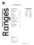
cdt'oaaut 09,u, I 9 Èi J'sc ement naule lenslon ^tg' rcr:aEe nsulatron :ester Noticed'utilisation U s e r ' sm a n u a l SEFRAM et Systèmes lnstruments 3 2 , R u e E d o u a r dM A R T E L F421OOSAINT.ETIENNE T e l : + 3 3( 0 ) 4 7 75 9 3 6 8 1 F a x : + 3 3 (0 )47 7 5 7 2 3 2 3 Site WEB : U,vWSe-traf .lf e-mail : [email protected] S u p p o r tt e c h n i q u e; + 3 3 ( 0 ) 47 7 5 9 3 6 9 6 R é f é r e n c eM : 918000M00 Fq!??fi| -24- o o o 1. Prescriptionsde sécurité fuLanuel d'utilisatlm Sommaire r . : s : : o t i o n sd e s é c u r i t é I ; ' - r : : e r r s t i or er so é n é r a | e s . . . . . . . . . . . . . . . . . . ^:.:e L e s c h o c sé l e c t r i q u epse u v e not r e s e ^ t èc.e r l a ^ q e r sp o u rl a s a n t é . ll est importantde lire et de respecterscrupûteus.nentlesprescrtptions de sécuritéde ce manuel. ? À lérrctinrroc 3ranchements................ S:ecifications................. F a c ea v a n t . . !: cuette Instructions simplifiées.. i . l t s ee n c e u v r e . . . . . . . . . a . e n r p l a c e m ednets p i l e s . edt u f u s i b l e . . . . '.larntenance = : r E n g l i s ht ,u r nt o p a g e . . .... . . . A  n -7 B-'10 1n a4 tz / 7ft ! \ Gjl ^^ / L\ | \ / . L ' a p o a r edr o l r rê r . e; t , t r s eo a rr u o e . s o n n eql u a l i f i é e t f o r m e a u xo i s p o st o r s a o r e n o r eq u a n tà l a SecLlflte Su. leS nStallattons e ectroues . N e j a m a r so u v r rvr o t r ec o n t r ô l e udr' i s o l e m e nh to r m i sp o u r r e m p l a c e' e r s o r i e sS e r e f e r ear - c n a p i t r e< R e m p l a c e m e n t OeS Plles ). ^ / L\ 4\ ^ / 4\ Z_3 ^ / L\ Z.-3 . L'apparen r le d o i tj a m a i sê t r eu t i i i s és u rd e s c i r c u i t s o u s tensron. . D a n sl e c a so u a p r è sb r a n c h e m e nu tn b e e pe s t é m i sp a r I'appareo r u s r l a f f i c h a g e( L t V EC t R C U t T > (soust e n s r o ne)s ta l l u m éi,m m é d i a t e m ednét c o n n e c t ev ro t r e c o n t r ô l e ucre I ' i n s t a l l a t i o n . . N e l a m a r se x o o s e,r' a p p a r ear I ' e a u- r i s q u ed e c h o c électrique 2 . C o n d i t i o n sd ' u t i l i s a t i o n e t c a r a c t é r i s t i q u egsé n é r a l e s . u t r l r s a t rà o nl ' i n t é r i e u r . catégone d ' i n s t a l i a t i oC n A Tl l l 3 0 0 V . t-.1 t-l A A donrô .le nnilrrtinn ? . altitude d ' u t i l i s a t i o: 2n 0 0 0m e t r e sm a x i m u m D o u b l er s o l e m e n t D a n g e .R i s q r , o e e c h o cé l e c t n q u e Attention. se référèrau manuel Ce contrôleurd'isolement a une tensionde sortievariablede 500Và r e 5 0 0 V .l l e s t m u n rd e ' f n e n u se" t u t i l i s eu n et e c h n i q u e 1 O K Vp, a r p a l i e d dynamiquede sélectionde mesuredu courant.La lignedu dessusindique le temp passéainsique la résrstance d'isolement. -)- -3- F f f f I 3. Caractéristiques . Affichagealphanumérique - 2 lignesde 16 caractères. . 20 tensionsde test : sOOV,,1 KV,2.5KV,2KV,2.sKV,3KV,3.sKV,4KV,4.5KV,sKV 5.sKV,6KV,6.5KV,7KV,7.SKV,8KV,8.5KV,9KV,9.SKVand .tOKV ajustableavec un palierde 500V . Pré-sélection de 4 tensionsde test:1KV,2.SKV,SKVet 1OKV. . Mesurede résrstance automatique (auto-range) sur tous les calibres. . Conforme à l a n o r m el E C 1 0 1 O . ' Indication vrsuellede la tensionde testsur Bar Graph(augmentation et réductionde la tensionpeuventêtreobservées. Compact,ergonomique. Livréen valisede protection. Mesureet indiquele tempspassépourla mesure. Déchargeautomatique des circuitssoustest. Indicateur sonoreet affichagede présencetensionavant(si >300VAC, dans le cas ou le circuità testern'estpas isoré)et aprèsretest (tension de décharge). Indicateur de pilesusées(surl'affichage). "EnerSave" Technologie poursauvegarder les piles. Faibleconsommation. F o n c t i o n n e m eanvt e c8 p i l e s1 , 5 V/ C ( a l k a l i n e s ) . Contrôlépar microprocesseur. Possibilite de verrouillage de la mesureen testd'isolement (mesure marns-libres). Arrêtautomatique ou manuelde la mesure. Arrêtautomatique du contrôleur. A . Branchgm€fltS ,*"r.oroR rsoLArÊuR 5. Spécifications . T e n s i o nds e t e s td e 5 0 0 V D Cà " a < , a C . € i a c e p a rp a sd e T S O O V D C . P r é - s é l e c t i o rnasp r d ed e t e n s r c nc o u r' 1K \ r 2 . 5 K V5, K V e t 1 O K V . . S é l e c t i oanu t o m a t i q udee s c a r b r e se t e c h e l l e s u rt o u t el e sg a m m e s . . M i n u t e r ijeu s q uà 9 9 9 S ' D i m e n s i o n s3 :4 0 x 2 7 0 x 1 7 0 m m . . Pords 3 6kn avee i2'tô..eS. . Detecteurde circuitsoustensionsi la tensronest supérreure à 300V. . Calibrea s u t o m a t i q u ecse 8 0 0 Ko h m sà 5 0 0 Go h m s . . P r é c i s i o .n! 1 0 o ' ct 2 p o l n t ss u rt o u t e sl e s g a m m e s . . T e m p e r a t u rdee f o n c t r o n n e m ednet :- 2 0 ' C à + 5 0 ' C . , A l i m e n t a t i opna r b a i l e r , e s i 8 x 1 . 5 V" C "- a l k a l i n e-s) . ' P u i s s a n cdee s o r te r m r t é e p a rl o g i c i eàl 1 W . , Courantde sorllelrmitéà '1.5mApar logicielen conjunction avec la l i m i t a t r odne p u i s s a n c e . Accessorres : . Option: ccrdonsde sécuritésiliconeet manueld'utilisation. C c r d o n a n t i - f u i t e ' " c o a xa' 'v e c g a r d e e t p i n c e |-rnnaÀrla rntonrÂa 1-a na." --,Jon coaxspecialest lmorègno e e s r l i c o neet s e d i v i s ee n d e u x : o n ^ e : t e u ' sr G a r d ee t L i g n e ) . Ce cordonempêcheles courantsde fuitede se piodurre( a gardeà l'interieur de ce cordon,capture L e sc o - r a n t sd e f u i t e q ) u ' i lp o u r r a iyt a v o r rl o r s q u ' u n l o n gc o r d o ne s t u t i l i s ép o u rl a l i g n e . E t a ^ c h e , tceo n t r el ' e a ue t l a o o u s s i è r e . À -+_ -5- 7. Etiquettedu couvercle Instructionssimplifiées 6 Face avant de I'appareil (:,i;l:il >. 3l l l '! G à ;l :iËîË: ËrË o ; ;gË:s:i! f l : l *,ËiË*giËËËi 3 € I ë EIË;e=;ËiË !iTËPiièee z a Ê: gËsËÈEËËËË Ëa È ul. I ô .^ c t o ; r iii::ii"r\ :îisii! : t iiÈfi;r:.I liî;;; :;\ :li!Ë! [-t a ri'\< .i::ai ii;:ai iÈ 1; 'lH ? :i : ; . i i r i! a :' ;q!a:i! :ùia  : :ija 4 i ; J 5 ! url iiii;ijËi fi i e i :i : i i i i : ; ;i :a i i ; :'ïÉ;ii ii ii;ii"i É;i: :::âç ;i i r ; ! i ; 11 5 ! ; i i i i l i Ë : Ê i ;r : :" i ;i"i 'i- : z ô ! E o --o z = rËË4: b ! ! F È 5 3É â Ë Ê9 zt'à " s" '*: €: iç3 2 â= E?! =,;: E:E: s .i ;ii srE::: Ë a = 5 3a : : < ro ! € Ë ls ÉEL 1 t ; i : i - ;: i É i i i ' i :s i : : i a Ê :_ i::q!ï: -igi :iii t J aÊ ii:i iE : I z z m I o z o m n zl ;::- lÉËu^';iiâ Ë;i! Ëi1Ë è d d a ! G : ! 6 1 1 - 5 E d À . ! 5 ËiEâiiËË 3- g -6- 8 . P r é c a u t i o n sa v a n tl e s m e s u r e s Avant d éffectuerune mesure,s'assurer: . C-e respilessoienten bon état(le contrôleur affichesi les batteries :r ,ient être remplacées. . :.e 'instrument et ses cordonsde mesuresoienten parfaitétat.en : a n : c u l i elr' a b s e n cdee c r a q u e l u r essu r l e sc o r d o n s . 9 . M i s ee n æ u v r e : ' l,1rse en marchéde I'aooareil Appuyersur le bouton" ON" O pourla miseen marchede Laooareil. : 2 À,1esure d'isolement à 10000VDC P o u rc h o i s i ur n et e n s i o nd e 1 0 0 0 0 V D Ca,p p u y esr u r e bouton1OKV(r. : J it.lesure d'isolement à 5000VDC Pourchoisirune tensionde 5000VDC,appuyersur le boutonsKV@. I I \ l e s u r ed ' i s o l e m e nàt2 5 0 0 V D C Pourchoisirunetensionde 2500VDC,appuyersur le bouton2.sKVO). : . d'isolement à '1000VDC "lesure Pourchoisirune tensionde 1000VDC,appuyersur le bouton1KV@ : a '.lesured'isolement à un multiplede 500VDC Pourajouter500VDCà la tensionaffichée,appuyersur le bouton+500V@. Poursoustraire 500VDCà la tensionaffichée,appuyersur le bouton-sOoV@ : [e modeENERSAVETM EnersaverM économisela duréede vie des oiles automatiquement en sélectionant la consommation la plus basse(réduitla duréedu test) EnersaverM est le modepar défautde l'apparert. Le mode EnersaverMest choisilorsquele bouton,fEST"(eest n r ê-c e - , -é- - ^F^ r, -r,r ,m,^,i n- , , , sd e t r o i ss e c o n d e lso r s q u ' utne s te s t démarré. -8- -vest rorsque L e m o d eE n e r s a v e annulQ l e o o u t o n' T Ë S J "3 est presséoourolusde troissecondeslorsqu'untest est d é m a r r éC. e l av e e ;dt i r eq u e l a d u r é ed u t e s ts e r ap l u s l o n g u e( 9 9 . 9 Se) t s a r r ê t e r as,o i tp a r I ' u t i l i s a t e(uarv a n lta f i n ) o u p a r l e c o n t r ô l e uarp r e s9 9 . 9 S ) . 9.8 Affichagede la tensionde sortie La tensronde sortieest affichéesur l'écranLCD sous la forme d ' u n eé c h e l l ed i g i t a l e 9.9 Détectionautomatjque de basserèsrstance (tropbasse) Touten étantdansle modede mesurede résistance d ' i s o l e m e nst i, l ' a f f l c h e ui nr d i q u e" L O W M Q " ,a r r ê t e r i m m é d i a t e m e nCte. l ap o u r r a i tn d i q u eqr u e I ' i s o l a t i onne s t p l u s intacteet que le contrôleur éssayed'in.jecter une hautetensron s u r u n e t r è sf a i b l er é s j s t a n c(em o i n sd ' u nM ( 2 ) m , ê m es u r u n courtcircuit!!! 9 . 1 0C h r o n o m è t r e L a d u r é ed u t e s te s t l n d i q u é se u r I ' a f f i c h e u( ar ud e s s u sà droite) pratiquepourvérifierque I'isolement C'estparticulièrement ne s'éffondrepas pendantla duréede test ou pourfaire d e sc o m p a r a i s o n s . 9 . 1 1S T O P P E Rl a p r o c é d u rdee t e s t Pourarrêterle testen cours,simplementappuyersur le bouton "TEST (!) Le resrarrèteraimmèdiatement et la décharge prendraeffect.A la fin de cettedécharge, automatLque l ' i n s t r u m e vnat l i d e r lae m o d eE n e r S a v e raMu t o m a t i o u e m e n t . 9 . 12 A u t o - S T O P Si I'operateur n arrêtepas la procédurede test,le contrôleur stopperaaprès99.95automatiquement. Aprèscela,si l ' o p é r a t e unre t o u r n ep a s l e c o n t r ô l e u" rO F F " l,e c o n t r ô l e u r ' s'arrêtera de lui-mêmè(auto-off) 9.13Autodétection de la tension- Attentionl!! Si les cordonssontconnectés sur un systèmesoustension, a v a n td e d é m a r r erret e s t .u n s o n ( b e e p- b e e p )s e r aa c t i v é pourattjrerI'attention automatiquement de I'opérateur et le " LiveWarning... CircuitLive"pour indiquer contrôleur affichera -9- que re circuitest soustension.LaisserIinstrumentdéchargerre crrcuit,ou si re circuitn'estpas isolé,ir faut isoierie circuitàvani de continueravecle test. 9.14Auto Décharge Lorsquele contrôleur a terminéIe test,il déchargele circuitde mesureautomatiquement (capacitif ou inductif)pourque la tensiondangereuse disparaisse. La déchargepeutêtre observéesur I'affichage (bargraph). Ne déconnecter les cordonsqu'aprèsune déchargecomplète( HOLD"). Pendantla décharge,le buzzerfonctionne, indiquantà l'opérateur que la déchargeest en courset que ce n,estpas fini. Lorsquela déchargeest terminée,un longbeepest émiset l'afficheur indique" HOLD,.Seulementaprès cela,vous pouvezenleverles cordons,en toutesécurité. 1 2 .M a i n t e n a n c e A u c u n em a i n t e n a n cne' e s tr e q u l s e , Nettoyerpériodiquement votreappareilavecun chiffondouxet h u m i d e( e a u ) . Ne pas utiliserde solvants. Toujoursvérifierque les cordonsde mesuresont en bon état (absencede craquelure). 9 . 1 5I n d i c a t i opno u rr e m p l a c el e r sp i l e s , , R e p l a B c ea t t e r y Si les pilessontuséesou faibles,I'affichage indiquera "ReplaceBattery". Ce contrôleur ne peutfônctionner correclement si les batteriessont usées. 9 . 1 6A u t o - O F F Le "AUTO-OFF" est annoncépar un longbeepdu buzzer(une secondeou deux).Cet auto_off timerest automatiquemeni mis en route par le logiciel,aprèschaquefin d,actionde l,opérateur ou du contrôleur. Le contrôleur peutêtrearrêté,,OFF,' par l,opérateur en pressant te bouton"OFF"plusde 5 secondes. 10. Préparationavant les mesures Avant d'effectuerune mesure,s'assurer: ^ / L\ ^/ , \ Q u el e s p r l e ss o n te n b o né t a t . Que I'instrument et ses cordonsde mesuresonten parfait etat,en particulier I'absencede craquelures sur les cordons. 1 1 .R e m p l a c e m e ndte s p i l e s Les pilessontsituéesdansle compartiment inférieurde votre boîtier.lmpérativement débrancher les cordonsde mesure avantd'accéderà ce compartiment. DévisserIe couvercle. Remplacerles piles(lesg simultanément). Revisserle couvercie. - tu- - 4I 4 t - Index 1. SafetyPrecautions D-rr.r. f clvç In d e x . . . . . . . . . . . S a f e t yp r e c a u t i o n .s..... . . . . .: . . . . . . . . . . . :. . . . . . Overview.... Features S p e c i f i c a t i o. n . .s. .... . . . . . . . . Instrument Layout Functions for Measurement Preparation Maintenance and CleaninoMethod InsulationResjstanceTesting tz 13 14 '15 16 17 18-20 a1 ZT 1.1 I 1.2 I 21 22-23 t.J 1A l_3 I I -tz- t.o 1.7 can causesevereinjuriesevenwith low voltageso' Electricity currents. Thereforeit is extremelyimportant that you readthe followng beforeusingyourdigitalinsulation tester. information mustonlybe usedand operatedby a This instrument with the competenttrainedpersonand in strrctaccordance instructions. We will not acceptliabilityfor any damageor injury with instructions and causedby misuseor non compliance safetyprocedures. mustnot be usedon live circuits.Ensureall This instrument beforetesting.See paragraph1.7for circuitsare de-energized detailsof built-inwarningfeaturesshouldyourdigitalinsulation tester be connectedto a livesystem. testerexceptfor battery Neveropenyourdigital insulation ( See BatteryReplacement section). replacement. testerand test leads Alwaysinspectyou digitalinsulation or damage.lf any beforeuse for any signof abnormality exist( brokentest leads,crackedcase, abnormalconditions or displayfaultyetc...) do not attemptto takeany measurement use the tester. testerto your nearestdistributor Returnyourdigitalinsulation for service. testerhas beendesignedwithyour Yourdigitalinsulation safetyin mind.However,no designcan completelyprotect circuitscan be dangerous againstincorrectuse.Electrical and/orlethalwhena lackof cautionor poorsafetypractrcers used.Use cautionin the presenceof voltageabove24V as theseposea shockhazard Pay attentionto cautionsand warningswhichwill informyou of potentially dangerousprocedures. testerhas a livecircuitwarningbeeoer.f Yourdigital insulatron it is connectedto a livecircuit,a rapidpulsatingbleepwill be disconnecl heard. DO NOT proceedto testand immediately fromthe circuit.ln additionyourtesterwrll the instrument displaythe.warnrngmessage. - tJ- T 2. Overview 3. Features testeris a variablehighholtage This digitalinsulation meterfrom 500Vto 1OKVin 500Vsteps. insulation The meteris menudrven and usesDynamicCurrent technology. Autoranging whichdisplaysthe voltage It is equippedwitha bar-graph whilethe test is in progressand stressingthe insulation the voltagedecayduringthe automaticdischargeof the tested circuit. The top lineof the displayshowsthe elapsedtimeat the startof the test.Digitalreadoutof the totaltimewill remain displayedevenaftertestinghas ceased. A 6 digitdigitaldisplayis showingthe actualinsulation resrstance. displaysa voltagewarningand sounds when This instrument the testvoltage. AC or DC is presentbeforein.iecting ! lt can only detectwhen voltage is higher than 500V. when highvoltageis generatedand It will buzzintermittently thiswill remainuntilthe circuitundertest is fullydischarged. -14- . 2 x 2 0 c h a r a c t e r sl a. r g ei n t e i l i g e L n .t C . DM . oduie. . 20 lnsulation testvoltages sOOV, 1KV,1.sKV,2KV,2,5KV,3KV,3.5KV,4KV, 4.5KV,sKV,5.5KV,6KV,6,5KV,7KV,7,sKV,8KV, 8,5KV gKV,9 sKV,1OKV . Insulation resistance auto-ranging on all range. . Ener-SaverM. . Bar graphindicatestestvoltage.Rise and decaycan oe oDserved. . Warningof externalvoltagepresence(>SOOVAC or VDC). . Overloadprotection. . Low batteryindrcator. . Measureinsulatron timerest. . Low batteryconsumption. . Smartmicroprocessor controlled. . Two yearsfactorywarranty. . Betterthan 10% accuracyon all range. . Auto-off. . C o m p a cat n d t i g h t w e i g h . 4. Connections INSULATOR ISÔI ÂTFIIO - tc- 6. InstrumentLayout. 5. Specifications TestVoltage PresetButtons From500VDC to 10KVDC Adjustablein 500V StePs TestLeadsConnections '1OKV 1KV,2.5KV,5KV, Measuring a 800Ko-500G Range AUTO-RANGING Accuracy t5%t2Digits Power Bx 1.5V Alkalinebattery OutputPowerLimit VoltageRegulation unlesscurrent Selected+20ok-5Yo limited Accessores Colorcodedflexiblesiliconetest manual leadsand instruction Option M W9 1 8 0 V.ctearaFautt . Startand Stop . G o t o M a i nM e n u Switches"ON" the Instrument Colorcoded, Anti-leakage, F l e x i b l sei l i c o n ceo a x i atle s tl e a d guard,intothe test with integrated probe Reset( if depressed.for less.thânone second) Switches"OFF"the lnstrument whendepressed for morethanfive seconds. - lo- ' t 4t -7 78 7. Functions 7.1 Power-On on, pressthe "ON"button@ To switchyour instrument t h e T h e L . C . Dw. i l ld i s p l a y m o d e ln u m b e r ' on L C D' instructions Then followinteractive Measurement @ 10000VDC lnsulationResistance To SelectlOKVDOtest voltage,press1OKVbutton@ I 9 Measurement @ SKVDC Resistance Insulation To Select5KVDCtestvoltage,pressSKVbutton(, 7.4 lvleasurement @ 2'5KVDC lnsulationResistance To Select2.5KVDCtest voltage,press2 sKV button(! ' 7.5 eeasuremen @t l K V D C l n s u l a t i oR n e s i s t a n cM To Selectl KVDCtestvoltage,press1KV buttonQ) Measurement @ Multipleof 500VDC lnsulationResistance 7.6 adjustment +500V To add 500VDCto the selectedtestvoltage,press 77 button @. to the selectedtestvoltage'press -500V To subtract5OOVDC button@. mode Ener-SaverM modesavesbaiterylifeby automatically The Ener-SaverM (reducingthe test to low consumption turningthe lnstrument duration). modeis the defaultmodeof the instrument' The Ener-SaverM modeis enabledwhen pressingthe TEST Ener-SaverM The than 3 seconds' less for button@ modeis disabledwhen pressingthe TEST The Ener-SaverM button@ for morethan 3 seconds' operates modeis disabled,the instrument When Ener-SaverM ' to 99.9s) (uP mode in continuous -18- 7 10 7 11 7 12 7.13 VoltageOutputBar-Graph The bar-graphshowsthe voltagepresenton the leads.lt also showsthe voltagecharginga cableor capacitive systemunder testand showsthe decayduringthe automaticcapacitrve dischargeof the systemunoertest. Detect Auto-LowResistance W h i l ei n i n s u l a t i otne s tm o d e ,i f t h e L . C . D m . o d u l es h o w s "LOW lVQ ", stopthe test immediately. Thiscouldmeanthat the insulation has a breakdown, thus, you are now tryingto injectvery highvoltageon a shortcircuit.Tryingto injecthigh voltageon a shortcircuitcouldresetthe rnstrument (specially if flashingoccurs). Timer The durationof the test is shownon the top rightof the L.C.D. This is particularly usefulto verifythat insulation does not breakdownwithina certaintime or to makecomparison. S T O Pt e s t pressthe TESTbutton@ The To stopthe testin progress. testwill immediately stop,dischargeand the instrument will enablethe Ener-Save1" modeautomatically. Auto-Stop Shorrlrjthc ônêretorleavethe Instrument in the test modewith theEner-Saverd Mi s a b l e dt h, e i n s t r u m e nwti l la u t o m a t i c a l l y stopthe testaftera duratron of 99.9seconds.(Auto-off still a p p l i e s) . Auto Live/ VoitageWarning Shouldthe leadsbe placedontoa livesystembeforestafiing activatedand , the test,a warningbeeperwil!be automatically y o u ri n s t r u m e n, w t i l l d i s p l a" yL i v eW a r n i n g. . .C i r c u iLt i v e ' message.Let the instrument dischargethe circuit( in the case of capacitive system)or makesurethatthe circuitundertesting i s n o tl i v e . -19- 7 . 1 4 . A u t o- D i s c h a r g e At auto-stopor test completion. the instrument automatically discharges the systemunderinsulation test so that the dangeroushighvoltageis discharged. The auto-discharge can be observedon the L.C.D.'sbar graphso that the operatoronly removesthe leadswhen the dischargeis complete.During discharge,a beepoccursso thatthe userdoeswait for the completedischargeof the systemundertest.This rs indicated by a one secondlongbeepaccompanied by the ,HOLD,, messageon the display. D O N O T R E M O V EL E A D SU N T I L T H EH O L DM E S S A G E A P P E A R SO N T H E D I S P L A Y 7 1 5 " ReplaceBattery"WarningIndicator lf the batteryenergyis detectedto be too low,the instrument will displaythe "Battery"warning. The instrument cannotoperateproperlywitha low battery. 7 16 Auto-Off The Auto-offis annunciated by a one secondbeep.The Auto-offtimeris automatically enabled.The instrumentcan also be switchedoff by pressingand holdingthe OFF key for m o r et h a n5 s e c o n d s . 8. Preparationfor Measurement Eeforetesting,alwayscheckthe following At Power"ON",readthe displayto makesurethe ,' Replace Battery"messagers not displayed. Thereis no visualdamageto the instrument or test leads. TestLeadscontinuity: Usinga Ohm-meter, checkthe resistance/continuity of the teaos. 9 . M a i n t e n a n ca e n d C l e a n i n gM e t h o d 9.'1BatteryReplacement Yourinsulation tester'sbatteryjs srtuatedunderthe tester The displaywillindicateyou when batteryneedsto be replaceC Disconnect the test leadsfromthe instrument and removethe batterycoverand the batteries. R e p l a c ew i t he i g h t A L K A L I N E1 . 5 V ' , C , , s i zt a e k, i n qc a r et o observecorrectpoiarity. Replacebatterycover. 92Cleaning&Storage Periodically wipethe casewitha dampclothano dererqent. Do not use abrasivesor solvents. lf the meteris not to be usedfor longperiodsor longerthan 60 days,removethe batteriesand storethemseoararerv. W ar ning To avoidelectrical shockor damageto the meter, do not get waterinsidethe cas e. 9.3 Calibration & Servicing Bothcalibration and servicingare performedonlyat an approvedfacility.Contactyournearestdistributor about calibration certificate and servicino. Beforereturnrng the tnstrument. e-nsure tha : . the teadshavebeencheckedfor continuity and s i g n so f d a m a g e . . the batteriesare in good condttion. -20- -21- 1 0 . I n s u l a t i o nR e s i s t a n c e Testing Warning: lnsulation testshouldbe conductedon circuitsthat are de-energized. Ensurecircuitsare not livebeforecommencing testing. . Securebothtest leadsproperlyto the insulation to test and use guard leadto collectsurfaceleakage. Good contactsare necessaryto avoidflashingat highvoltageor ionizatron or creationof carbontracktypeconductivematerial. . lf contactsare not properlysecured,the testermay be corrupted temporarily by the highelectromagnetic fieldpresent.Shouldthrsoccur let it resetitself. . Use onlybattery(Alkaline) to powerthis instrument . D O N O TU S EA N Y K I N DO F A D A P T E RO R C O N N E C T I OTNO T H E M A I N SP O W E R . "ON"by pressingthe "ON" button. Turn Instrument T h e L . C . D d. i s p l a yw i l lc o m ew i t ht h e m a k ea n d m o d e l , followedby to the followingscreen. Followthe lnteractive Screen. SelectInsulation testvoltaqe. For example,3500V To Select3500V,Press2.5KV,then presstwiceon +500VButton or PressSKV,then pressthreetimethe -500Vbutton The aboveScreenwill confirmyourselection.( voltageand MA Range) -22- =S-.ô ^ontirm vô,rr O n c e r e a d y t o a c c e p ty c L r s e e : : : ^ - . : i < SeleCtlOn -'1 ^ôn1ê.1thê IêSt T h e f o l l o w i n gs c r e e n ' ^ . . . . 2 ' leadS " - ' J ' _ ' ê i ' c nn lhc srrnnlia.i.rô..1,^ p r o p e r l yt o t h e i n s u i a t r o n' e s s : 3 ^ . 3 l f t h e s y s t e my o u a r ei n ' r n c : c : e s is î o t v o l t a g ef r e e ,a b e e ps o u n o T h e f o l l o w i nw g a r n i n gs c r e e n, ! i a : c e a r .R e m o v ey o u rl e a d si m m e d i a t e i y LIVEWARNINGMESSAGE/ BEEPER To ClearLiveW ar ningMessage/ Beeper Removeleadsfr omCir cuitundertes tand Pus h "TEST"buttonuntildisplayClear s . lf the systemis not live,the testwill startand the following screenwill appear;indicating: . the test duration(tophorizontal bar graphtype + digital) . the voltageoutput(leftverticalbar graphtype + digitalscaleindicator . the insulation (bottomhorizontal resistance log bar graphtype + digital scaleindicator) . the nsulationresistance (centervery largedigitaldispla) î s : r , m e n t s t o p s t h e t e s t . t h e l a s t r e s u l tw i l ' - : ' . I f T h e , n s t r u m e n ts w i t c h e s o f f . 1 . \ " . = - .: d : O OO w b e f o . e : h es t a n o f a : e s t , :-:-:: -tJ- ,:rl lo rec ace the batter\i