1
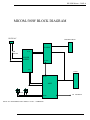
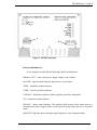
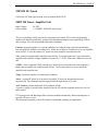
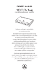
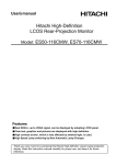
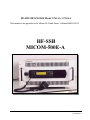
HF-SSB MICOM-500E Model G761AA / G762AA This manual is an appendix to the Micom 2E-Tr u nkOwn e r ’ sMa n ua l68 0 29 5 2C60 HF-SSB MICOM-500E-A Owne r ’ sMa nua l 6886858J01-A HF-SSB Micom –500E-A CONTENTS Introduction............................................................................................................................................2 General Specifications ...........................................................................................................................2 Block diagram........................................................................................................................................3 Controls and indicators ..........................................................................................................................4 General principles of operation..............................................................................................................5 500W HF Linear Amplifier Unit ...........................................................................................................6 DC Power Supply ..................................................................................................................................7 Junction Box ..........................................................................................................................................7 Performance Specifications ...................................................................................................................8 500W Transceiver Model Complements .............................................................................................11 Trouble Shooting .................................................................................................................................11 Radio Tuning Procedure ......................................................................................................................12 ALE......................................................................................................................................................12 1 HF-SSB Micom –500E-A INTRODUCTION The transceiver is a complete unit that includes Micom-2ET, 500watts amplifier , power supply, e nc l os e dt og e t he ri na19”dr a we r .Thec ont r olhe a doft her a di oi spl a c e dont hedr a we r ’ sf r ont panel. The unit includes a movable drawer, which allows to detach the control panel of the radio and moved up to 5 meters away (cable extension included). The transmitter amplifier is microprocessor controlled, doing the following functions: - Adjust amplifier input sensitivity - Monitor heat, VSWR, and under voltage conditions, - Setting the power output via the channel power setting (Max, High, Medium and Low) GENERAL SPECIFICATION Power Output: 1.6-30MHz: 500W PEP and average Band Switching: Fully Automatic Input Voltage: 220VAC-10A /110VAC-20A Cooling: Cooling fans T/R Switching time: 10mS nominal Band Switch time: 100mS nominal Protection: Input over drive under voltage (adjustable): Factory default 28+/-3 VDC Amplifier module Current imbalance VSWR faults Frequency out of Specified range over current over temperature. 2 HF-SSB Micom –500E-A MICOM-500W BLOCK DIAGRAM 110/220 AC CONTROL HEAD RADIO 13.8v SW ON/OFF POWER SUPPLY RF OUT 28v J-BOX RF IN AMP FAN SENS RF OUT NOTE: ALL THE WIRES AND CABLES CAT No - 01MB000027 3 TO ANTENNA HF-SSB Micom –500E-A Controls and Indicators Power IAmplifier module has the following controls and indicators: Indicator VOLT –shows when power supply voltage is out of limits. In OVER –input overload indicator. Input power is out of limits. TEMP –amplifier overheat indicator. L K VSWR –load circuit failure indicator. FAILURE –fatal failure indicator, further amplifier operation is impossible. TX –transmission mode indicator. Figure 1. PA 500 front panel Controls and Indicators Power Amplifier module has the following controls and indicators: Indicator VOLT –shows when power supply voltage is out of limits. In OVER –input overload indicator. Input power is out of limits. TEMP –amplifier overheat indicator. VSWR –load circuit failure indicator. FAILURE –fatal failure indicator, further amplifier operation is impossible. TX –transmission mode indicator. BYPASS –bypass mode indicator. The amplifier shall operate in this mode when it is disconnected to power supply, faulty, can not operate by any other reason or is in receive mode. BAND OUT indicator shows that input signal frequency is out of operation band. 4 HF-SSB Micom –500E-A General principles of operation Block diagram of the power amplifier is shown at Fig.4. Input RF signal with 25W nominal l e ve lc ome st hr oug h“ RF I n”c onne c t ort o TS1 227 boa r d ofPAMP 500 a mp l i f y i ng de vi c e consisting of 4-channel power splitter and 4-channel amplifier. The power splitter unit contents: Input signal level sensor; Input relay Rx/Tx that provides the possibility to operate in BYPASS mode; Input signal attenuator used by the amplifier protection system; Signal frequency sensor; Power splitter. The signal comes from power splitter output to four 150W amplifying sections inputs. Then, amplified signal is summed by power Combiner (TS5 226). The signal then comes from Combiner output to harmonic filter (TS5 223) input and then t oout putl e ve ls e ns or ,out putr e l a yRx/ Txa ndt oo ut putc onne c t or“ RFOUT”. The controller provides the power amplifier control, status monitoring and its protection in emergency situations. By analyzing the input signal level, the controller provides protection of the amplifier input against overloading. By measuring the input signal frequency the controller selects and switches on appropriate harmonic filter. Control system also provides the control of the amplifier sink temperature. Depending of its level the forced air cooling system shall be switched on or output power level shall be reduced if necessary and if the temperature limit is exceeded the amplifier shall be switched to BYPASS mode. By analyzing signals from output sensor the controller monitors the status of load, and if VSWR in the load is higher than maximum allowed one the controller decreases output power, and if VSWR is higher than 4 the controller switches the amplifier to BYPASS mode. Besides, the controller sends to CONTROL output connector the signals that proportional to forward and reflected power at the amplifier output and that assigned for output power control from an external device, for example, exciter. Thus, the amplifier control system provides full its status and operability control. It switches the amplifier to BYPASS mode in the following cases: VSWR > 1:4 Input signal frequency is out of operation band The temperature mode is out of limits In other cases, as well as in switched off mode when normal operation of the amplifier is impossible. In that case the possibility of normal operation of external transceiver is provided. 5 HF-SSB Micom –500E-A MICOM 2E-Trunk For Micom 2E-Trunk specification see user manual 6802952C60 500W HF Linear Amplifier Unit Input Voltage: Power Output: 28 VDC 1.6-30MHZ: 500W PEP and average The power amplifier is fully protected by microprocessor control. This circuitry dynamically monitors all amplifier parameters, and provides adjustments and protection against high VSWR, under voltage, over current and high temperature conditions. Current- protection against over current condition (exceeding 60 amps) and current imbalance between amplifier modules (exceeding 20%). When one of these two conditions exists, the amplifier turns off-line. To reset the transceiver, power down the amplifier and restart the unit. Volt - protection against under amplifier turns off-line. To reset the transceiver, power down the amplifier and restart the voltage condition (less than 28+/-3 VDC). When this condition exists, the unit. VSWR –when a sampled VSWR exceeded 4:1 and the power reflected back to the amplifier is higher than acceptable, the amplifier turns off-line. To reset the transceiver, power down the amplifier and restart the unit. Temp - protection against over temperature condition Atten –as input RF power level increases beyond 60-70 watts, the attenuation increases automatically. The Attenuate remains engaged until the input drops to 30 watts. ALC Control- provides adjustable ALC feedback voltage. A positive voltage is present on the Amplifier line for use with the equipped transceiver for ALC input control. PTT keying mode and Band input filter selection enabled automatically. Band switching time is typically 100 msec or less. This automated capability is ideal for remote or unattended operating site application. 6 HF-SSB Micom –500E-A 3. DC Power Supply Model: Nominal Output Voltage: Input Voltage Range: EWS1500-15 28V-50A----14V-30A 85~132 VAC / 170~265 VAC (Auto Selectable), 47~63 Hz 110/220 VAC power supply - if need to convert the power supply from 220VAC to 110VAC, please detached the 110/220VAC panel at the rear panel of the unit and short the A and B terminals. The ON/OFF switch on the front panel of the unit, enables to turn the power supply output on and off. Note that, when the dc output power supply is on OFF mode, the internal power supply fans still work. 4. Junction Box The junction box enables the connection of up to four external devices simultaneously, in addition to headphone, to the accessory port of the MICOM –2 (e.g. modem, phone patch.) Potentiometers adjust - Potentiometers are used to adjust the received audio levels (one of each connector). Each potentiometer is associated with a connector as follows: ACC. -J1: RX1 ACC. -J2: RX2 ACC. -J3: RX3 ACC. -J4: RX4 The potentiometers are located on the rear panel of the MICOM-500E. For more details see Service Manual 68P02952C55 7 HF-SSB Micom –500E-A PERFORMANCE SPECIFICATIONS for 500W TRANSCEIVER GENERAL Frequency Range XMIT 1.6 –30 MHz Frequency Range RX 0.1 –30 MHz (0.1 - 1.6 MHz reduced spec) RF Input Impedance 50 Ohms Number of Channels 200 SIMPLEX or HALF DUPLEX Scanning 1 5 groups with up to 100 channels per group, including 1 guard channel. Programmable scan rate: 1 - 5 sec. per channel, in 1 sec. steps Frequency Stability 0.6 PPM @ -10to 60 C Frequency Drift (Aging) 1 PPM/year Synthesizer Lock Time 10 msec. Max Frequency Resolution 10 Hz Operating Temp. Range -10to +60 C Storage Temp. Range -30to +70 C Humidity 95% @ 50 C Remote Control Interface RS232C (Optional) Modes of Operation J3E SSB R3E PILOT H3E AME J2A CW J2B RTTY, ARQ, FEC, PACKET, MCW B8C FAX, DATA, FSK Dimensions Height (mm/inch) 265/10.43 Width (mm/inch) 422/16.61 Depth (mm/inch) 508/20 CURRENT CONSUMPTION @ 14 VDC / 28VDC ( INTERNAL CURRENT ) XMIT Voice (500 W P.E.P.) 38 Amp Receive Full Audio Squelch 1 2 Amp 1.7 Amp ALE specification see user manual 6802952C60 8 HF-SSB Micom –500E-A TRANSMITTER Output Power 500W P.E.P. and average +/-1dB Reduced Power Levels 500W, 400W, 300W, 200W (RSS programmable) Audio Bandwidth2 350 to 2700 Hz at –6dB Audio Bandwidth Ripple 3 dB Intermodulation -31 dB / 500W P.E.P Spurious Emissions -60 dB / 500W P.E.P Carrier Suppression -50dB / 500W P.E.P Undesired Sideband Suppression -55dB / 500W P.E.P Audio Distortion 2.5% 1/2 Power Mic. Sensitivity 15 to 125mV (RMS)/600 Ohms Hum & Ripple -50 dB Inband Noise -60 dB (30 Hz BW) TX/RX Switching Time 10 msec Tx Tuning Adjustments3 None RECEIVER Sensitivity (SINAD) SSB 0.5 V for 10 dB SINAD (0.35 V Typical. Note 1) 0.1 - 1.6 MHz with reduced performance 1/2 Rated Power Sensitivity 1 V for 2.5W audio at speaker Selectivity2 - 6 dB @ 350 to 2700 Hz –60 dB @ -1 kHz; +4 kHz Image Rejection -80 dB IF Rejection -85 dB RECEIVER (continued) 2 See Micom 2E spec. for more Bands widths. 3 For tune procedure wait about 2 sec when stepping from one channel to another before transmitting. 9 HF-SSB Micom –500E-A Undesired Sideband Rejection -55 dB @ -1 kHz Spurious -80 dB Intermodulation -80 dB Crossmodulation -100 dB @ 100 kHz Desensitization -100 dB @ 100 kHz Reciprocal Mixing -100 dB @ 100 kHz Audio Power at Speaker 5W @ 2.5% distortion RGC Range RGC Time Constants Voice 5 V to 1V (2 dB change in output level) Attack time 10 msec Release time 1500 msec Data Squelch Attack time 10 msec Release time 10 msec Constant SINAD (digital) Clarifier Range 200 Hz Receiver Tuning Adjustments None Maximum Antenna Input 20 kV transient, 100V RMS for 2 minutes CONTROLS Standard and optional: volume, on/off, scroll, squelch, scan, USB/LSB, call, monitor, priority, func and accessory/programming connector. Specifications subject to change without notice. 10 HF-SSB Micom –500E-A 500W TRANSCEIVER MODEL COMPLEMENTS M81AMN0KV5AK * MICOM-2ET FDN6144A FPN5585A FRN5865A Amplifier 500 watts Power supply Junction box 01MB000027 01MB000029 01MB000030 FMN1615A Cables Chassis Miscellaneous Microphone * NOTE: LORD No-FLN3179A HIGH POWER No-FLN3180A with interface modification for 500w amplifier TROUBLE SHOOTING In case of malfunctioning, perform the following steps (refer to the Maintenance section in MICOM-2E Owner’ s manual, Motorola publication number 6802952C60). 1. Turn OFF and ON the radio switch to reset both the radio and the amplifier. 2. Use BITE when the channel is in SSB mode only 3. Refer to the User Troubleshooting Chart. 4. Follow the troubleshooting procedures in this section, which provide instructions for isolating faulty boards. Troubleshooting a board at component level should be performed according to the notes on the relevant schematic diagram. FAULT VOLT trip off-line VSWR trip off-line Amp TEMP led is on. No PTT Keying ADVICE Ensure power supply maintains voltage greater than 11.0VDC under load. Check DC cable connections. Check integrity of antenna and feedline connections. Check for evidence of arc-over or dielectric breakdown of feedline. Ensure antenna is resonant (<2:1 SWR) at the desired operating frequency. Reduce drive level or duty-cycle. Ensure fan unit is operating properly. Ensure transceiver, amplifier and DC supply all utilized a common ground. 11 HF-SSB Micom –500E-A RADIO TUNING PROCEDURE Before operating the 500W transceiver, a calibration procedure should been taken. An IBM PC and RSS (Radio Service Software) package, FLN2514, are required to align the radio.(factory setting) 1 .Ont h ea c c e s s or i e ss e c t i o n, pl e a s ema r kt hec he c kboxoft he“ 1 kwAmpl i f i e r ” . 2. There are 4 steps of power outputs as noted above. If you need to perform a power calibration, please refer to the power calibration procedure in the MICOM-2E RSS manual. ALE Automatic Link Establishment (ALE) is an embedded feature inside the Micom-2E/R ALE family of mobile/fixed station HF-SSB radios. Through the combined use of channel scanning, selective calling and Link Quality Analysis, ALE automatically selects the best available communications link. It is no longer necessary for an operator to be familiar with the varying factors, which affect high frequency (HF) propagation between two points. Each ALE equipped Micom-2 ALE family radio stores a matrix of Link Quality Analysis (LQA) scores for all other stations in the HF network. Memorized LQA scores are derived from an analysis of channel "soundings" which are periodically transmitted by each network station. When an operator selects the individual or net call address of the receiving station, ALE automatically determines the optimum available channel and automatically initiates calling procedures. Sending and receiving operators are alerted when a communication link has been established. 12