1
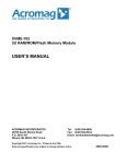
中綴じ Instruction Manual EG-225 DIGITAL LINEAR GAUGE *Outer appearance and specifications are subject to change without prior notice. HOME PAGE: http://www.onosokki.co.jp/English/english.htm WORLDWIDE ONO SOKKI CO., LTD. 3-9-3 Shin-Yokohama, Kohoku-ku, Yokohama 222-8507, Japan Phone : +81-45-476-9712 Fax : +81-45-470-7244 E-mail : [email protected] in/ mm MODE POWER RESET +/- B00000278/IM89013101(4) 102(MS)02K ONO SOKKI CO., LTD. Warranty 1. This product is covered by a warranty for a period of one year from the date of purchase. 2. This warranty covers free-of-charge repair for defects judged to be the responsibility of the manufacturer, i.e., defects occurred while the product is used under normal operating conditions according to descriptions in this manual and notices on the unit label. 3. For free-of-charge repair, contact either your sales representative or our sales office nearby. 4. The following failures will be handled on a fee basis even during the warranty period. (a) Failures occurring through misuse, mis-operation, or modification (b) Failures occurring through mishandling (dropping) or transportation (c) Failures occurring through natural calamities (fires, earthquakes, flooding, and lightening), environmental disruption, or abnormal voltage. * For repairs after the warranty period expired, contact your sales representative or our sales office nearby. 1. This document may not be reproduced, in whole or part, in any form or by any means without the prior written permission of the publisher. 2. The contents of this document are subject to change without notice. 3. This document has been produced based on a series of strict verifications and inspections. Should a failure occur nonetheless, please inform our sales representative or sales office. 4. Ono Sokki shall have no liability for any effect resulting from any operation, whether or not the effect is attributable to a defect in the documentation. Copyright ONO SOKKI CO., Ltd. 2004 All rights reserved. 中綴じ INTRODUCTION CAUTION Your new EG-225 Digital Linear Gauge has passed a strict quality control program. To ensure that you get the most out of your new instrument, we strongly recommend that you read and follow this instruction manual. The EG-225 Digital Linear Gauge consists of the following parts. The rubber o-ring mounted on the spindle serves as a stopper for the spindle. Do not attempt use of the gage with this o-ring removed, as this can cause failures. When the spindle’s top point screw is removed (e. g. to mount the lift lever), always insert the o-ring before reassembling. The manufacturer cannot be held liable for failures caused by use with the o-ring removed. • Main Unit • Finger Lifter • PB-701 Power Supply • Instruction Manual Top point screw Spindle Before using the linear gauge, check that all the required parts have arrived and, should there be a shortage, contact your sales representative. O-ring Spindle cap Main body –1– Before Using this Gauge • Before using the EG-225, remove the rubber ring which is used to hold the spindle in place. • Over-discharge can occur during shipment. If the EG-225 is to be used with both battery and AC power, first charge the battery sufficiently. (The recharging method is described in Section 4, power supply connection.) • When using the EG-225 for the first time, press the power switch and reset switch simultaneously to perform a system reset. • When the voltage of the internal rechargeable battery falls below a reference level (approx. 4.7V), “B” will appear on the LCD display. If operation is continued in this condition, when the voltage falls below approximately 4.6V, “B” will appear on the LCD display and the power will switch off automatically. In this condition, if the power is switched on once again, “B” will appear for approximately two seconds and the power will be switched off once again. If “B” appears, the battery should be –2– recharged. (Do this with the power switched off.) In addition, when the battery is fully discharged, even if the power is switched on, nothing will appear on the LCD display. In such case, after charging the battery, press the power switch simultaneously with the reset switch to perform a system reset before beginning measurements. TABLE OF CONTENTS 1. 2. 3. 4. 5. 6. 7. 8. 9. 10. 11. 12. Page FEATURES .................................................................................................................... 4 PARTS ........................................................................................................................... 6 FUNCTIONAL DESCRIPTION ...................................................................................... 7 POWER SUPPLY CONNECTION ............................................................................... 13 DISPLAY DESCRIPTION ............................................................................................ 14 OPERATION DESCRIPTION ...................................................................................... 16 MOUNTING METHOD ................................................................................................. 20 CONNECTION OF THE FINGER LIFTER .................................................................. 21 OPERATING PRECAUTIONS ..................................................................................... 21 SPECIFICATIONS ....................................................................................................... 23 OVERALL VIEW .......................................................................................................... 28 WARRANTY ................................................................................................................ 28 –3– 1. FEATURES The EG-225 compact digital linear gauge conforms to AGD Group II mechanical specifications. Its excellent response enables spindle travel up to 20 in/s (500 mm/s). With a resolution of 0.00005, it is possible to make measurements with a stroke of 1 inch. Three measurement functions (normal, absolute zero, and preset) are available for selection, depending upon the particular application. In addition, it features selection of either English or metric readout and has a serial data output. • Three measurement functions: normal, absolute zero, preset • A stem, back and body that satisfy AGD Group II specifications make the EG-225 directly interchangeable with existing mechanical gauges. Combined with commercially available fixture, the EG-225 can be used as a depth gauge or snap gauge. • A linear gauge technique is used to provide a high degree of ruggedness and highly stable accuracy. • Selectable English or metric unit. • Any arbitrary position can be set as the reference point (in the normal function, this is set at zero, and in the preset function, this is set at a given value). • By using a direction switch, it is possible to select the counting direction. (In the absolute zero function, the direction is fixed as the direction, and for the preset function, the direction is fixed as the direction selected for the normal function.) • Switched mode display of maximum value, minimum value and range. (In the absolute (ABS) zero function, the MAX., MIN., R mode function does not operate.) • Dual power supply enables operation from either an AC line (using an AC adaptor) or a selfcontained rechargeable battery. • Can be combined with RQ-2110 Printer to perform data recording and statistical calculations. • Can be connected to RS-232C devices via the BH-100 Interface Unit, enabling highly efficient SPC processing. –4– In addition compatible with all major SPC systems • Data-Myte • OS Gage talker • Verax • QMS Genesis • Dataputer –5– 2. PARTS a b c d e f g h i j k l m n l Power Switch Reset Switch Direction Switch Mode Switch Inch/mm Switch LCD Display Spindle Cap DC Input Connector Protective Cap Output Connector Protective Cap Finger Lifter Contact Tip Mounting Lug Stem Spindle DATA OUT DC IN i h g f d b in/ mm e MODE POWER +/- RESET c a m k –6– n j 3. FUNCTIONAL DESCRIPTION First, we will describe the functions of each part, as used in the normal basic measurement function. Of the EG-225 parts, the operation in the absolute zero or preset function will be noted only when it is different from operation in the normal function. <Normal function> a Power Switch When the power switch is pressed, the EG-225 is powered and measurement is possible. When this is done, the LCD display reads “0”. b Reset Switch When this reset switch is pressed and then released (within two seconds), the display value is reset to “0”. When this happens, the output is “no data” when the reset switch is pressed and the display is blank, and is “0” when the reset is released and the display changes to “0”. When the switch is allowed to return to its original position, “0” is indicated on the display and the current spindle position is the zero point. c Direction Switch The measured value is incremented or decremented, depending upon the direction of spindle movement. The counting direction can be selected either to add or subtract when the spindle is pressed in, depending upon the setting of the direction switch. The counting mode is indicated by the or mark on the display. : Addition (+ direction) when spindle is pushed in. : Subtraction (– direction) when spindle is pushed in. d Mode Switch Each time the mode switch is pressed within two seconds, the mode is sequentially changed from the normal measurement mode to the maximum value, the minimum value display mode, –7– then the (R) range (maximum to minimum) display mode, and finally back to the normal measurement mode. (1) In the normal measurement mode, the measured value is continuously displayed. (2) If the mode switch is pressed one (within two seconds), “MAX” appears in the display, indicating that the maximum value display mode has been reached. In this mode, read-in measured values are continuously compared and the maximum value measured is displayed. (3) If the mode switch is pressed a second time, (within two seconds), “MIN” appears in the display, indicating that the minimum value has been reached. In this mode, measured values are continuously compared and the minimum value measured is displayed. (4) If the mode switch is pressed a third time (within two seconds), “R” appears in the display, indicating that the range value display mode has been reached. In this mode, the maximum and minimum values are internally registered in accordance with the up/down movement of the spindle, with the range value (maximum-minimum value) displayed continuously. (5) If the mode switch is pressed once more (within two seconds), “R” is extinguished from the display and return is made to the normal measurement mode. The initial value for the MAX, MIN and R display mode is the value displayed when a switch is made to the MAX mode from the normal mode. Once set, the initial value is held until the reset switch is pressed (within two seconds) and then released. If it is necessary to set initial value once again, perform a reset. The previous initial value will then be cancelled and the displayed value when a switch is made from the normal mode to the MAX mode will be set as the initial value. (When a reset is performed, the data output is “no data” when the reset switch is pressed and the display is blank, and is “0” when the reset switch is released and the display changes to “0”.) –8– e Inch/mm Switch h DC Input Connector Protective Cap This switch selects either “inch” or “mm” as the units for display of the measured value. The units are alternately selected each time the switch is pressed. The selected mode is maintained even when the power is switched off. The “in” and “mm” annunciators will appear in the display to indicate the selected unit. Note that it is also possible to press the switch after a measurement has been made to convert the units indicated in the display. This is the protective cap for the DC input connector. It is removed to enable the plug of the PB-701 power Supply to be inserted into the connector. When the PB-701 is not being used, it is always important to replace this cap to prevent dust entering the unit. For details on the power supply, refer to Section 4, Power Supply Connection. f Display This (LCD) liquid crystal display indicates the measured value and includes a sign. For details, refer to Section 5 describing the display. g Spindle Cap i Output Connector Protective Cap This is the protective cap for the output connector. When output is not required, it is always important to cover the connector with the protective cap to prevent dust from entering the unit. A serial output representing the displayed value is available at this connector. Before making a connection, always switch the power supply off. For details on the seral output, refer to Section 10, Serial Output Specifications. By inserting the connector from the RQ-2110 Function Printer (option) into this connector, it is possible to create a printout of not only measured values but to perform statistical calculations –9– and recording of outputs as well. Using the optional BH-100 Interface Unit, any computer which is equipped with RS-232C interface can be used (with user application software) to perform such functions as editing and calculation on measured values. <Absolute Zero and Preset Function> j Finger Lifter If the normal function is set, and the RESET switch is pressed for more than two seconds and released, the display will indicate “AB”, indicating that the absolute zero function has been selected. If the RESET switch is pressed once again and released, return is made to the normal function. If the switch is pressed further, the absolute zero and normal functions will be selected alternately. In the absolute zero function, the RESET switch cannot be used to set the display value to zero. k Contact Tip l Mounting Lug This lug is used to mount the gauge to a mounting fixture. m Stem This stem is grasped and held to mount the gauge to a gauge stand. n Spindle 1. Reset switch <Absolute zero function> <Preset function> When this function is selected, the RESET switch has two functions. (1) If the RESET switch is pressed for less than two seconds and released, the displayed value in the NORMAL, MAX, – 10 – MIN mode will be the preset value and, in the R mode, the preset value will be zero. (2) If the RESET switch is pressed for more than two seconds and released, return is made to the normal function. After this, if the switch is pressed further, the absolute zero function will be selected. 3. Mode Switch <Absolute zero function> In this function, mode switching is not possible (i.e., it is protected). <Preset function> 2. Direction Switch <Absolute zero function> In this function, the direction cannot be changed. It is fixed as the direction <Preset function> In this function, the direction cannot be changed. It is fixed as the direction selected in the normal function. In the normal function, if the MODE switch is pressed for longer than two seconds, the “P” mark appears in the display and the preset function is ready for use. In this function, the MODE switch has two functions. (1) If the mode switch is pressed for less than two seconds, the preset mode is reached and the sequence normal → MAX → MIN → R is switched through, after which return is made to the normal mode. (2) If the mode switch is pressed for more than two seconds, switch is made to the preset setting procedure. The preset value setting is also made using this mode switch. For details, refer to Section 6, Preset Setting Procedure. – 11 – 4. Inch/mm switch <Absolute zero function> In this function, it is not possible to perform inch mm switching. In this function, the unit is fixed at the position selected in the normal function. <Preset function> In this function, it is not possible to perform inch/mm switching. In this function, the unit is fixed at the position selected in the normal function. – 12 – 4. POWER SUPPLY CONNECTION (2) Battery Operation (1) PB-701 Power Supply Remove the protective cap from the round connector hole at the top of the gauge and insert the plug of the PB-701 into this connector. By connecting the PB-701 in this manner, the unit operates from AC line power. Cord length:5.9ft Note 1. When the PB-701 is not being used, always be sure to replace the protective cap to prevent dust from entering the gauge. 2. If the self-contained rechargeable battery is completely discharged (i.e., if even the “B” does not appear when power is switched on), insert the PB-701 plug and charge for approximately 30 seconds. Then perform a system reset to enable the display and make possible operations from the AC line. The EG-225 has a self-contained rechargeable battery. In order to recharge the battery, connect the PB-701 to the EG-225 for 16 hours with the power switch OFF. When used in this fully charged condition, the battery will give continuous operation for 8 hours. • When the voltage of the internal rechargeable battery falls below a refernce level (approx. 4.7V), “B” appears on the display. If operation is continued in this condition, when the voltage falls below approximately 4.6V, “B” will appear on the display and the power will be switched off automatically. In this event, if the power is switched on once again, “B” will appear for approximately two seconds and the power will be switched off once again. If “B” appears, the battery should be recharged for 16 hours. This should be done with the power switched off. – 13 – 5. DISPLAY DESCRIPTION In addition to the measured value, the display indicates the following types of messages. in: This annunciator indicates that inches have been selected as the measurement unit. mm: This annunciator indicates that millimeters have been selected as the measurement unit. These annunciators correspond to the setting of the inch/mm switch. MAX: This indicates the maximum value display. The displayed value does not change unless a measured value greater than the displayed value is entered. MIN: This indicates the minimum value display. The displayed value does not change unless a measured value less than the displayed value is entered. R: This indicates the range (i.e., difference between maxi- mum and minimum values). The MAX, MIN and R modes are selected sequentially by pressing the mode switch. E: This error display indicates that the spindle has been moved at a speed greater than the allowed limit, a condition causing possible measurement value error. Because the spindle response speed is up to 500 mm s, a counting error rarely ever occurs. Should “E” appear in the display, however, indicating a counting error, set the power switch to OFF to cancel “E”, switch power ON and begin measurement once again. B (B): This indicates that the battery voltage has fallen below a set limit. When “B” appears in the display, it is time to recharge the battery. If measurements are continued after “B” appears in the display, to prevent complete battery discharge, “B” will appear after a few seconds, approximately two seconds after which the power will be switched off automatically. – 14 – Switch power ON once again, “B” will appear for approximately two seconds, after which the power will be switched off automatically. : This indicates the counting direction. : Addition (+ direction) when spindle is pushed in. : Subtraction (– direction) when spindle is pushed in. +: This indicates that the measured value is positive. For negative value, “–” will appear in the display and for a measured value of 0, no sign is indicated. AB: This indicates that the absolute zero function has been selected. P: This indicates that the preset function has been selected. If “P” is flashing, this indicates that the preset setting procedure is in progress. – 15 – 6. OPERATION DESCRIPTION As long as the system reset is not performed, the following three parameters will be held in memory even with the power switched off. 1. inch mm selection 2. Preset setting value 3. / direction When the power is switched ON, the normal function will be selected automatically. This normal function is used as the basis for switching to the absolute zero function or preset function. (1) Normal function The normal function is the basic measurement function. Note that switching of direction and switching between units (inch/mm) are possible only in this mode. It is possible to press the reset switch (for less than two seconds) and release it to set the display value at the time the switch is released to zero. When this is done, the output is “no data” when the reset switch is pressed and the display is blank, and is “0” when the reset switch is released and the display changes to “0”. During measurement, if “E” appears, set the power to OFF to cancel “E”, switch power ON and begin measurements once again. Since the spindle response speed is fast (500mm s), the “E” hardly ever appears. Each time the mode switch is pressed (for less than two seconds), the sequence NORMAL → MAX → MIN → R will be switched through. If the R mode is selected, the maximum and minimum value are internally registered in accordance with the up/down movement of spindle, with the range value displayed continuously. The MAX, MIN, R mode initial value is the value displayed when the MAX mode was switched to from the normal mode. Once the value is set, it is held in memory as long as the reset switch is not pressed (for less than two seconds) and released. If the initial value requires resetting, perform a reset operation. When doing this, the previous initial value is cancelled and the value displayed at the time the maximum mode is selected from the normal mode will be set at the new initial value. The data output when a reset is performed is “no data” when the – 16 – display is blank, and changes to “0” when the display changes to “0”. If “E” appears in the display during a measurement, set the power to OFF as would be done for the normal measurement mode. (2) Absolute Zero Function (3) Preset Function The spindle position when the power is switched ON is taken at the absolute zero point, and the absolute zero function keeps constant track of the displacement from this position, displaying the difference. To switch from the normal measurement function to the absolute zero function, press the RESET switch for longer than two seconds. When this is done, “AB” will appear on the display, indicating that the absolute zero function has been selected. If the switch is pressed for a longer time, the absolute zero and normal functions will be selected alternately. In this function counting direction will be limited to the direction. The inch/ mm unit is limited to the unit selected in the normal measurement function. Note that the direction and inch/mm switching are protected and cannot be changed in this function. The mode switch becomes inoperative. The RESET switch is only usable to return to the normal measurement function. The preset function is used to add a preset offset value to measured values for display. It is only possible to switch to the preset function from the normal measurement function. If the mode switch is pressed for longer than two seconds in the normal measurement function, the “P” appears in the display, indicating that the preset function has been selected. Simultaneously with selection of the preset function, the setting value will be displayed (or “0” will be displayed if the offset value has not been set). Note that in this function, the direction and inch/mm switching are protected (i.e., disabled). The direction and inch/mm system are held at the selections made in the normal measurement function. The RESET switch operates to set the displayed value as the setting value. Press the RESET switch (for less than two seconds) and re- – 17 – lease it to set the offset value at the instant the switch is released. The preset value setting procedure is noted below (Preset Value Setting Procedure). If “E” appears during measurement, perform a reset by switching the power off. By pressing the mode switch (for less than two seconds) it is possible to switch through the sequence NORMAL → MAX → MIN → R, after which return is made to the normal mode. The MAX, MIN, R mode initial value is the displayed value at the instant the MAX mode is reached by the normal mode. Once the initial value has been set, it is held until the RESET switch is pressed (for less than two seconds) and released. If it is necessary to change the initial value, perform a reset. When doing this the previous initial value will be cancelled and the displayed value at the moment the MAX mode is selected from the normal mode will be set as the new initial value. When the reset is performed, the data output is “no data” when the RESET button is pressed and the display is blank, and it changes to “0” when the RESET is released and the display changes to “0”. In the MAX, MIN, R mode if the RESET button is pressed (for less than two seconds) and released, the initial value will be can- celled and for the MAX or MIN mode the display will change to the setting value. In the R mode, the display will be reset to “0”. To return from the preset function to the normal measurement function, press the RESET switch for longer than two seconds. <Preset Value Setting Procedure> If the mode switch is pressed for longer than two seconds in the preset function, “P” and “+” or “–” will flash on the display, indicating that the preset value setting procedure has been entered. When this procedure is followed, the measurement units will disappear from the display. Set the units in the preset function. The maximum setting value is 6.99995 for inch units and 69.999 for mm units. It is not possible to set values above these limits. The RESET switch is operative in returning to the preset function. Press the Mode switch for less than two seconds, and the “+” or “–” should flash alternately. When the desired setting polarity appears, press the MODE switch for longer than two seconds. When this is done, the polarity selected will be set. At the same time, the flashing point will move sequentially to the right. – 18 – When the digit to be set is flashing, release the mode switch. At this point, if the MODE switch is pressed for less than two seconds, each time it is pressed the digit value will change sequentially from 1 through 0 and return to 1. However, if the inch unit is selected in the preset function, the final digit is limited to a value of 0 or 5. When the setting of the final digit is completed, “P” only flashes in the display. When it is necessary to perform the setting again, press the MODE switch one more time for less than two seconds. The flashing position will once again return to “+” or “–”. If the setting value is OK, press the MODE switch for two seconds or longer and the “P” will stop flashing, the unit will be displayed, and return will be made to the preset function. Note: When the RQ-2110 set limit data (upper lower limit value) is being set, this preset value setting procedure is more important and useful. Thus, even during a setting procedure (i.e. when the display is flashing), the data value can be transmitted, so that the limit set switch on the RQ-2110 can be pressed to set the limits ON. – 19 – (2) Lug Mounting 7. MOUNTING METHOD (1) Mounting By Grasping the Stem The diameter of the stem is 0.375/0.374”, enabling mounting on either an optional gauge stand (ST-022, ST-044B with option) or a stand which has been prepared by the user as shown in the figure below. 0.376/0.375"DIA Pass a bolt through the lug mounting hole (0.25” diameter) on the rear cover and tighten securely. When mounting by this method, if the tightening force is insufficient, the gauge may be tilted towards the bottom about the ears. Take care that this does not occur. Use flat and spring washers on both sides as shown in the figure below. The lug can be rotated 90° by removing the screws on the rear cover. t=0.630" Tightening screw Care should be taken not to apply excessive force to the stem. – 20 – 8. CONNECTION OF THE FINGER LIFTER 9. OPERATING PRECAUTIONS The finger lifter can be inserted between the lift screw and the spindle by removing the contact tip at the end of the spindle as shown in the figure below. (1) When mounting to a fixture, always be sure that the mounting is made so that the direction of spindle movement and the long direction of the object being measured agree and that the spindle makes contact at the proper position. Also, the mounting fixture should have sufficient strength and exhibit no bending. Stem Spindle Lift Screw L L Finger Lifter Contact Tip Direction of spindle movement should agree with L direction. – 21 – If, as shown above, the direction of spindle movement and direction L do not agree, error will occur in measured values. (2) Replacement of Contact Tip When replacing the contact tip, hold the spindle firmly using a rubber band or similar material. Spindle Rubber band (3) Lowering and raising of the spindle should be performed by the AA-970 accessory finger lifter or the optional AA-971 Top Lifter. (4) Care should be taken not to TOUCH the spindle with the hands as dirt on the spindle can impair smooth movement. If dirt has accumulated on the spindle, wipe it off with a cloth dampened with alcohol. (5) If the gauge has not been used for a long period, recharge the battery and perform a system reset. (6) Since the gauge is made of high-precision components, avoid disassembling it or treating it roughly. (7) After use, remove dirt from the contact tip and spindle, using a dry soft cloth. (8) If the outer case becomes soiled, wipe it with a dry soft cloth. If the core becomes extremely soiled, wipe it with a cloth slightly dampened with a neutral detegent. Avoid volatile organic solvents such as thinners, since these types of liquid may damage the case. – 22 – 10. SPECIFICATIONS Measuring range ................... 1 in. (25.4mm) Resolution ............................. 0.00005 in. (1µm) Accuracy at 68°F (20°C) ....... 0.00012 in. (3µm) Response Speed .................. 20 in/s (500 mm/s) Display .................................. 6 digit LCD with sign Measuring Force ................... 0.33 lb [1.47N (150gf)] Power supply ......................... AC adaptor (100/120/220/240 V) or selfcontained rechargeable battery (continuous operation for 8 hours on full charge) Operating temperature .......... 41° to 104°F (5° to 40°C) Mass ..................................... 6.3 oz (180g) Serial output specifications ... Refer to serial output specifications. – 23 – SERIAL OUTPUT SIGNAL SPECIFICATIONS 2. Output signal Electrical Characteristics 1. Connector Pin Arrangement All signals are output CMOS devices (1 LSTTL load drive capacity). HIGH ........ VOH>4.OV(VCC=4.5V, IOH=–10µA) LOW ......... VOH<0.4V(VCC=4.5V, IOL=1.8mA) AA-963B Connection Cable Linear Gauge RQ-2110 33k Connector Type: 60-8283-3058-15001 (Female connectors on both sides of AA-963B cable) 008283-0511-00000 (Male connectors on linear gauge & RQ2110) Manufacturer: Elco (Japan) PIN NUMBER 1 2 OUTPUT SIGNAL SIGNAL COMMON CLOCK 3 4 5 DATA RESET MODE 2SC1843 33k Linear Gauge 3. Output Signal Description (1) Signal Common: Common line for all signal lines (2) Clock: Timing clock for the four bits of data (refer to the timing diagram). Frequency: Approx 125KHZ – 24 – (3) Data: As shown in the table below, data consists of 12 steps which represents one value, each step consisting of four bits, output in the sequence 23 → 20. Step 1 2 3 4 5 6 7 8 9 Name FH EH 105 digit data 104 digit data 103 digit data 102 digit data 101 digit data 100 digit data Decimal Point Sign 23 1 1 23 23 23 23 23 23 0 0 0 0 1 1 1 22 1 1 22 22 22 22 22 22 0 0 1 1 0 0 1 21 1 1 21 21 21 21 21 21 0 1 0 1 0 1 0 20 1 0 20 20 20 20 20 20 0 1 – 25 – Description Step 1 is indicated by FH EH indicates that the next value is the 6th 6th digit (105) of linear gauge LCD is output 5th digit (104) of linear gauge LCD is output 4th digit (103) of linear gauge LCD is output 3rd digit (102) of linear gauge LCD is output 2nd digit (101) of linear gauge LCD is output 1st digit (100) of linear gauge LCD is output 1 2 3 4 5 6. 1 2 3 4 5.6 1 2 3 4.5 6 1 2 3.4 5 6 1 2.3 4 5 6 1.2 3 4 5 6 .1 2 3 4 5 6 “+” sign “–” sign Step 10 11 12 Name Unit Not use MAX MIN END 23 0 0 0 0 0 0 0 22 0 0 0 0 1 1 1 X 21 0 0 1 1 0 0 1 20 0 1 0 1 0 1 0 Max. 0 0 0 Min. 0 – 26 – Description No Unit m/s inch/s rps rpm inch mm Not used High for maximum display High for minimum display End of output of one value (4) RESET: Reset function can be externally controlled by inputing a low-level signal to the output connector pin No.4. 4. Timing Diagram 5V 0V 5V 0V V OH V OL Min 30 ms RESET button ON CK1 CK2 CK3 CK4 CK1 CK2 CK3 CK4 CK1 CK2 CK3 CK4 Step 1 (5) MODE: Mode function can be externally controled by inputing a low-level signal to the output connector pin No.5. V OH V OL Min 30 ms MODE button ON – 27 – Step 12 data (Approx 1.6ms) 11. OVERALL VIEW 1.988 CORD LENGTH:5.9ft DATA OUT 1.299 0.750 DC IN 0.394DIA. 0.256 1.614 2.362 2.5 1.378 0.413 WITH FINGER LIFT 1.122 1.122 0.197DIA. 0.827 0.375DIA. 1.063 0.785 0.624 1.785 0.039 0.25 +/- 3.262 RESET 0.098 MODE 0.250 1.313 2.165DIA. in/ mm POWER 0. 25 DI A. 2.047DIA. AC ADAPTER FPB-701 – 28 – 中綴じ Instruction Manual EG-225 DIGITAL LINEAR GAUGE *Outer appearance and specifications are subject to change without prior notice. HOME PAGE: http://www.onosokki.co.jp/English/english.htm WORLDWIDE ONO SOKKI CO., LTD. 3-9-3 Shin-Yokohama, Kohoku-ku, Yokohama 222-8507, Japan Phone : +81-45-476-9712 Fax : +81-45-470-7244 E-mail : [email protected] in/ mm MODE POWER RESET +/- B00000278/IM89013101(4) 102(MS)02K ONO SOKKI CO., LTD.