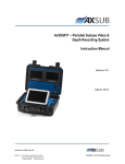
1
User’s Guide and Warranty Information
PurePower 100/110/120 Volt models
PurePowerTM
Contents
Table of Contents
About the PurePower APS
2
Safety Warnings
3
Installation
Inspecting the Equipment
4
PurePower Preparation
5
Activating Up Your PurePower
8
Operation
10
PurePower Maintenance
13
Specifications
14
Troubleshooting
16
Service and Support
17
Audio/Video Power Supply • www.purepoweraps.com
| 01
About the PurePower APS
The PurePower Audio Power Supply
The PurePower Audio Power Supply (APS) provides pure regenerated power for your sensitive
home theater and audio equipment. This is accomplished through our double conversion technology. We convert the incoming AC power to produce a clean DC supply, then recreate a new AC
wave form with propper voltage and frequency from the DC. We make sure that your system gets
the power it was designed for and your amplifiers get the current they need for top performance.
The APS also protects from power disturbances including power sags, power surges, overvoltages, line noise, undervoltages, frequency variations, switching transients and harmonic distortion. Power disturbances have the potential to damage sensitive hardware causing expensive
repairs with either catastrophic failures or degradation over time through chronic overheating.
With the APS you can safely eliminate the effects of power disturbances and guard the integrity
of your equipment.
In addition to pure power, the APS provides you with something unique in audio power
regenerators - protection against power outage. The APS maintains full wattage output even
when the power fails completely.
Providing outstanding performance and reliability, the
PurePower’s unique benefits include the following:
• True double conversion AC regeneration design with pure sine wave output. The APS filters
and regulates incoming AC power, creates a DC source, then regenerates new pure AC and
provides monitored, consistent power to your components.
• The APS improves amplifier performance by ensuring full wattage and improves signal
component output quality by removing noise and distortion.
• The PurePower APS design allows any of our high quality, full contact receptacles
to supply digital, analog or amplifier components.
• Hours of extended viewing or listening time with optional APS PowerPack Modules
during outages.
• Built in line surge protection guards against spikes and surges on coax, RJ11and RJ45 lines.
• USB communiction port allows the APS to be integrated into whole home systems.
02 |
Pure Power in > Pure Sound out
Safety Warnings
Safety Warnings
Read the following precautions before you install the APS.
IMPORTANT SAFTEY INSTRUCTIONS - SAVE THESE INSTRUCTIONS.
This manual contains important instructions that you should follow during installation and maintenance of the APS and batteries. Please read all instructions before operating the equipment and
save this manual for future reference.
DANGER
This APS contains LETHAL VOLTAGES. All repairs and service should be preformed by AUTHORIZED
SERVICE PERSONNEL ONLY. There are NO USER SERVICEABLE PARTS inside the APS.
WARNING
This APS contains its own energy source. The output receptacles may carry live voltage even when
the APS is not plugged in.
Under normal operating conditions, do not remove or unplug the input cord when the APS is
turned on. This removes the safety ground from the APS and the equipment connected to the
APS.
To reduce the risk of fire or electric shock, install this APS in a temperature and humidity
controlled, indoor environment, free of conductive contaminants. Ambient temperature must not
exceed 32°C (90°F). Do not operate near water or excessive humidity (95% max).
To comply with international standards and wiring regulations, the total equipment connected
to the output of this APS must not have an earth leakage current greater than 3.5 milliamperes.
CAUTION
Batteries can present a risk of electrical shock or burn from high short-circuit current. Observe
proper precautions. Servicing should be preformed by qualified service personnel knowledgeable
of batteries and required precautions.
Proper disposal of batteries is required. Refer to your local codes for disposal requirements.
Never dispose of batteries in a fire. Batteries may explode when exposed to flame.
Audio/Video Power Supply • www.purepoweraps.com
| 03
Installation
Inspecting the Equipment
Before installation, please check to ensure that your PurePower APS package is complete and
undamaged. If any deficiencies are discovered, please contact your PurePower Dealer.
Package Contents
The PurePower package includes:
PurePower APS
Quick Start Guide
Input line cord with an IEC female connector to fit the PurePower input connector and a Nema
5-15P (700 and 1050) or Nema 6-20P (2000) plug.
Rack mount bracket kit
This manual
Shipping damage
If any equipment has been damaged during shipment, keep the shipping cartons and packing
materials for the carrier or place of purchase and file a claim for shipping damage. If you discover
damage after acceptance, file a claim for concealed damage.
To file a claim for shipping damage or concealed damage:
1) File with the carrier within 15 days of receipt of the equipment
2) Send a copy of the damage claim within 15 days to your PurePower APS dealer.
04 |
Pure Power in > Pure Sound out
Installation
APS Preparation
The APS is designed for flexible configurations and can be rack mounted or placed on a shelf or
as a standalone cabinet.
Standalone / shelf component
When you position the APS horizontally on a shelf or in a non-rack style AV equipment stand or
enclosure, ensure there is sufficient clearance for unimpeded airflow through the grilles at front
and rear of the unit.
Rack-Mount
The APS can be installed in 19 or 23-inch racks and needs only 2U of rack space for 700 adn
1050 models, 3U for the 2000. Mounting rails or a rack shelf are recommended.
Place the APS on a flat, stable surface with the front of the APS facing toward you.
Attach the mounting handles to the bracket with the screws provided in the accessory kit.
If installing optional PowerPacks, install rack handles for each unit.
NOTE The PowerPacks must be installed BELOW the APS.
Mounting
Handle
Mounting
Bracket
Audio/Video Power Supply • www.purepoweraps.com
| 05
Installation
Connections
The PurePower APS 700 and 1050 provide 8 Hubbell NEMA 5-15 output receptacles that may
be used interchangeably to power signal components, video components or amplifiers. The 2000
provides 10 Hubbell 5-15 receptacles.
Surge protection connectors
The PurePower unit provides built in surge protection to isolate system components such as cable
television, satellite, ethernet and telephone lines from your AV system.
The surge protection is not provided specifically to protect satellite receivers, computer network
and telephone equipment from damage from surges -- although it does that task admirably. The
main purpose is to prevent satellite or cable TV coax cables, telephone and ethernet lines from
providing a path that would allow surges or spikes to damage your AV system that is otherwise
isolated from surges arising in the AC power lines by the PurePower APS. It is intended to prevent
a back door attack that would circumvent the PurePower protection.
All surge modules provide instantaneous response using advanced silicon avalanche diodes with
the ability to safely dissipate surge currents of up to 1kA and auto reset in readiness for any subsequent surge or transient voltage.
Coax
Telephone
Network
Connector
Type F (2)
RJ11 4 wire
RJ45
Voltage
30
190
5
USB and DB9
Let through
45
<298
10
Bandwidth
2 GHzT
na
155MHz
USB and DB9 serial connectors are available to allow communication of power conditions to an
attached computer system. Contact PurePower for system requirements and software compatability.
06 |
Pure Power in > Pure Sound out
Installation
Installing Optional Power Packs
Power Pack Modules must be installed before powering the APS. In a rack mount installation, place the Power Packs below the PurePower unit.The optional 36 volt PowerPack for the
PurePower 1050 is attached to the PurePower main unit with an umbillical cord that fits a
PowerPack Connector that is only built into PurePower units ordered with this feature. The connector is a factory installed option.
If your PurePower 1050 is not equipped with a Power Pack connector and you wish to add one
or more Power Packs, the unit can be factory retrofit. Please contact PurePower service for details.
All PurePower 2000 models incorporate a PowerPack connector that mates only with the 72 Volt
PowerPack designed for the 2000.
For both 1050 and 2000 models, up to 3 PowerPacks may be daisy chained together to provide
extended operating time.
CAUTION: A small amount of arcing may occur when connecting a PowerPack Module to the
APS. This is normal and will not harm you. Insert the connection cable into the APS battery connector quickly and firmly.
· Plug the first PowerPack cable into the battery connector on the APS rear panel
· If additional PowerPacks are to be installed, plug the cable of the second cabinet into the
battery connector on the previous Powerpack
NOTE: The batteries charge to 80% capacity in approximately 2 hours. However, it is recommended that the batteries charge for 24 hours after installation or long-term storage. The battery
charging process will occur during normal operation and will not interfere with the supply of
power from the APS.
Audio/Video Power Supply • www.purepoweraps.com
| 07
Installation
Activating your PurePower APS
The following steps explain how to install and start the APS.
Activating the APS
· Examine the rear panel label to ensure the voltage specifications of the unit and the
power source are correctly matched.
· Plug the components to be supplied into the APS output receptacles. The PurePower APS
design allows any outlet to supply digital, analog or power amplifier components.
· Ensure that each component is switched off.
· DO NOT operate electric space heaters or other items with heater elements with the APS.
· On the 2000 model only, ensure the input circit breaker is switched to "on"
· Plug the APS power cord into a utility outlet. The APS conducts a self-test. You may hear
a slight click and the fans will rotate momentarily. When the self-test is complete, the APS
is in standby mode.
· Start the APS by pressing the On/Off button until the blue LED is illuminated..
When the blue "Output" LED is illuminated, power is being supplied to the PurePower output
receptacles. The APS will operate in Bypass mode for a few seconds, then turn on its inverter output - indicated by the LCD Display. The PurePower APS is now in Normal mode and ready to supply power to your system. Turn on the components, ensuring that the total load does not exceed
the capacity of the PurePower APS.
After initial start up it is best to keep the APS on at all times to ensure its batteries are fully
charged. Battery charging will continue with the unit turned Off so long as it is plugged in to an
AC supply.
If the LCD lights fail to illuminate after plugging the unit in and pressing the On/Off button, check
the line cord, ensure AC power is available at the receptacle and check the line fuse located in
the back of the unit before notifying PurePower service.
If the amber "Fault" LED is illuminated there may be a problem requiring sevice of the APS.
Please call our support line for instructions.
In no circumstances should the lid of the PurePower unit be removed. Ther are no user serviceable components inside and there may be lethal voltages present even if the unit is unplugged
from the wall.
08 |
Pure Power in > Pure Sound out
Installation
Turning the PurePower On
After the APS is connected to a power outlet, it conducts a self-test and enters Standby mode,
during which it will operate its batteries charging circuit, but all output receptacles are off.
To turn on the APS output power, press the On/Off button on the front panel for 2 to 3 seconds
until the blue "Output" LED illuminates. The LCD display will indicate "bypass" for a few seconds
and then indicate "Line Normal" mode and display the output voltage.
Starting the PurePower APS on battery
To turn on the APS when utility power is unavailable, press and hold the On/Off button until the
blue "Output" LED illuminates. The APS supplies power to your equipment and goes into Battery
Mode. When the APS starts on battery, it does not conduct a self-test to conserve battery power.
It will automatically return to Line Normal when utility power becomes available.
Turning the PurePower APS off
To turn off the APS press and hold the On/Off button until the blue "Output" LED turns off.
Power to the APS output receptacles will be off. If you do not unplug the APS, it remains in
Standby mode and the batteries will remain fully charged.
Initiating the Self-Test
Press and hold the On/Off button for one second while the unit is in "Line Normal" mode to
initiate the self-test. During the 10-second test, the unit will switch to batttery operation and the
display will read "testing" .
NOTE: The batteries must be charged and the APS must be in normal mode to perform the selftest.
Audio/Video Power Supply • www.purepoweraps.com
| 09
Operation
Operation
The PurePower unit indicates the APS status through the LCD Display. Pressing the "Display"
button on the control panel will cycle through the 5 information displays.
The display presents data on 2 lines. The top line indicates the current operating mode:
Line Normal
Bypass
Battery Backup
Testing
Short Circuit
Over Load
The information, presented on the bottom line of the display are:
Output Voltage & Frequency
Input voltage & Frequency
Temperature (C/F)
Battery Level
Load Level
Line Normal
During Normal mode, the display indicates the percentage of APS load capacity being used by
your system. The APS monitors and provides power to your system and charges the batteries as
needed.You may press the "Display" button to read the input and output voltages, temperature,
battery condition and load level.
10 |
Pure Power in > Pure Sound out
Operation
Bypass Mode
In the event of an extended APS overload or internal failure, the APS transfers your system to utility power. Battery mode will not be available, however the utility power continues to be passively
filtered by the APS. The LCD display will indicate "Bypass" when bypass mode is engaged. The
APS switches to Bypass mode when:
· When The APS is turned on it operates from Bypass for 10 to 20 seconds
· The APS has an overtemperature condition.
· The APS has an overloaded condition of 101 to 110% for 2 minutes.
· The APS has an overloaded condition of 111 to 150% for up to 30 seconds.
· The APS detects a fault in the battery or APS electronics.
Battery Backup Mode
When the APS is operating during a power outage, the "Battery" screen is presented on the
LCD display and the "Utility Power" LED on the conrol panel will not be illuminated. The LCD
panel displays the approximate percentage of battery capacity remaining. When the utility power
returns, the APS switches back to Normal mode operation and the batteries recharge.
If battery power is exhausted the APS will shut down. The low batery warnings are approximate,
and the actual time to shutdown may vary. When utility power is restored after an APS shut
down, the APS automatically restarts.
Audio/Video Power Supply • www.purepoweraps.com
| 11
Operation
Test Mode
When the APS is operating in Normal Mode, pressing the On/Off button momentarily causes the
APS to enter test mode for 10 seconds. The APS will then operate on battery and complete a self
test.
Short Circuit
The Short Circuit mode indicates a problem with either an external circuit plugged in to the
APS or a possible internal problem. Unplug each load in turn. If the problem continues after all
loads have been removed the message may indicate a problem with the APS itself. Please notify
PurePower Service for further instructions.
Over Load
When the APS detects an overload condition its behavior varies with the amount and duration
of the overload. Short overloads of 1% to 10% can be sustained for several minutes, overloads
up to 50% can be supported for up to 30 seconds. Overloads above those levels or durations will
result in the APS switching to bypass and supplying power from the utility feed until the overload
condition is cleared. The APS will only switch to bypass if it determines that the utility supply is
acceptable. Otherwise it will initiate a shutdown.
12 |
Pure Power in > Pure Sound out
APS Maintenance
PurePower Maintenance
PurePower APS
For the best preventive maintenance, keep the area around the APS clean and dust-free. If the
atmosphere is very dusty, clean the outside of the system with a vacuum cleaner. For full battery
life, keep the APS at an ambient temperature of 21° C (72° F).
Storing the APS and Batteries
If you store the APS for a long period, recharge the batteries every 12 months by plugging
the APS into a power outlet. The batteries charge to 80% capacity in approximately 2 hours.
However, it is recommended that the batteries charge for 24 hours after long-term storage.
When to Replace Batteries
When the battery load indicator remains low (below 50%) even after a prolonged charge cycle,
the batteries may need replacing. Conduct a self-test by holding the On/Off button momentarily
while the unit is in "Line Normal" mode . The unit will switch to battery mode for 10 seconds to
test the batteries. If the test indicates a battery fault, contact PurePower or your PurePower dealer
to order new batteries. The average battery life is aproximately 5-7 years.
The PurePower APS will still provide full power conditioning including output voltage correction
and surge protection when the batteries need replacement, but it will not be able to continue to
operate during a power outage.
You may perform the battery replacement yourself by ordering a PurePower battery replacement
kit. Full instructions are included with the kit and are also available on our web site.
Battery compartment acccess
Removing the Phillips screws (size 01) on the top front of the APS allows the front assembly
to hinge forward. This provides access to the battery compartment for battery replacement or
cleaning the fan area. Do not remove the lid. Lethal voltages are present inside the unit. Before
attempting any operation in this area, turn off the APS, unplug the unit, open the hinge, disconnect the battery pack by pulling apart the battery connector, then press and hold the on/off
button for 3 seconds to discharge stray voltages. Follow all instructions in the Purepower Battery
replacement data sheet available on our website.
Audio/Video Power Supply • www.purepoweraps.com
| 13
Specifications
Specifications
This section provides the following specifications for the PurePower APS
· Electrical input and output
· Weights and dimensions
· Environmental and safety
· Battery
Model List
PurePower APS Model 700
PurePower APS Model 1050
PurePower APS Modl 2000
Electrical Input
Nominal Voltage
Voltage Range
Frequency Range
Noise filtering
Input Connections
Electrical Outputs
Output Voltage
Voltage Regulation
Voltage Waveform
Output Receptacles
Energy Efficiency
14 |
VA/Watts Weight Lb (Kg)
1000/700
34 (15)
1500/1050 60 (27)
2000/1400 80 (36)
Dimensions (HxWxD)
3.5" x 17" x 19"
3.5" x 17" x 20"
5.25 x 17 x 22.5
100/110/120
80 – 145V
45-65Hz, 50/60 Hz auto-sensing
MOVs & line filter for normal & common mode noise
700/1050 IEC-320 -cC3 15 amp Input connector
2000 IEC 320-C19 20 amp Input connector
100/110/120 (factory set)
Nominal output voltage ±2%
Normal mode: Sine wave; <3% THD with full PFC
Hubbell Nema 5-15R
89 - 92 % depending on load
Pure Power in > Pure Sound out
Specifications
Environmental and Safety
Operating Temperature
Optimal battery performance:
Storage Temperature
Transit Temperature
Relative Humidity
Operating Altitude
Transit Altitude
Audible Noise
Surge Suppression
Safety Conformance
0°C to 32°C (32°F to 90°F)
21°C (72°F)
0°C to 25°C (32°F to 77°F)
-25°C to 55°C (-13°F to 131°F)
5-90% noncondensing
Up to 3,000 meters above sea level
Up to 10,000 meters above sea level
Less than 17 dBA
ANSI C62.41 Category B (formerly IEEE 587)
cULus
Class B EMC Statement
FCC Part 15
Note: This equipment has been tested and found to comply with the limits for a class B digital
device, pursuant to part 15 to the FCC Rules. These limits are designed to provide reasonable
protection against harmful interference in a residential installation. This equipment generates,
uses and can radiate radio frequency energy and, if not installed and used in accordance with
the instructions, may cause harmful interference to radio communications. However, there is no
guarantee that interference will not occur in a particular installation, in which case the user will
be required to correct the interference at his own expense. Any changes or modifications not
expressly approved by the party responsible for compliance could void the user's authority to
operate this equipment.
Audio/Video Power Supply • www.purepoweraps.com
| 15
Troubleshooting
Troubleshooting your PurePower APS
This section contains troubleshooting information and an explanation of APS alarm conditions.
Condition
Possible Cause
Resolution
The LED indicator lights
are not on or APS won’t start
Power cord not connected
Wall outlet is faulty
APS Fuse or breaker blown
Check connections
Have outlet checked and repaired
Clear Cause and Replace Fuse
Amber Fault LED illuminated
Receptacle ground wiring fault,
Short circuit on output
Internal fault
rewire receptacle
Remove load, repair short
Notify PurePower Service
Utility LED off, Battery mode indicated Utility power failure
APS is not connected to wall
none
Check Input power cable
Bypass indicator is lit
APS in bypass mode
Check LCD message for cause.
Your components have been transferred
to utility power. Power filtering and
surge suppression are active.
APS shuts down
Overload or over temp condition
and Utility power bad
Utility failure and batteries depleted
Reduce load, check for obstruction and
fan operation
APS will restart when utility returns
Battery % indicator low
Battery fully discharged
Allow batteries to charge for 24 hours
then hold On/Off button for 1 secs.
for self test.
Replace the batteries or contact your
dealer.
Battery failure
Internl temp over 65 degress C.
Internal temp too high
Turn off and unplug APS, allow
to cool. Check for blocked vents
and that airflow is not restricted. If
problem persists, contact your dealer.
Overload message,
APS turns off output
Power demand exceeds
APS overload capacity*
Turn off and unplug APS. Wait 5
seconds, restart APS. If problem
persists, remove components from
APS until wattage is within APS rating.
Some amplifiers have very high
power draws* on startup.
A higher wattage APS may be required.
Amplifier startup demands
* The APS is capable of supporting up to 110% of its rated capacity for 2 minutes and up to 150% of its rated capacity for up
to 30 seconds. Turn on multiple high power amps one unit at a time.
16 |
Pure Power in > Pure Sound out
Service & Support
Service And Support
For setup and support for your PurePower APS, please contact your authorized
PurePower Dealer.
For warranty service, please contact your authorized dealer or PurePower. All PurePower APS
models have a two year warranty for original registered owners. If we are unable to solve a problem with your APS over the phone, we’ll provide fast repair or replacement.
For technical support and warranty service, and full RMA instructions please contact PurePower
via:
email: [email protected] | phone at 519.624.9735 | fax at 888.336.4293
Audio/Video Power Supply • www.purepoweraps.com
| 17
Aug 1 2008
Pure Power in > Pure Sound out • www.PurePowerAPS.com