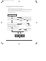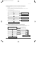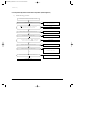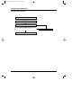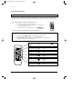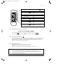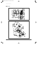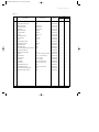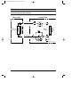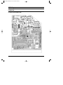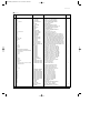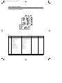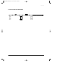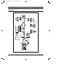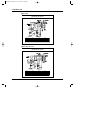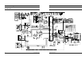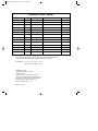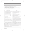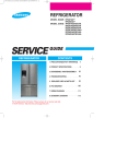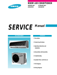
1
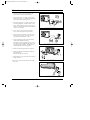
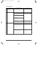
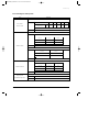
DB98-04268A(1)-SH30ZC1-CO 1904.1.14 9:57 AM 페이지3
ROOM AIR CONDITIONER
INDOOR
SH32ZC1(C2)
AQT30C1(C2)BB
AQT32C1(C2)BE
SERVICE
OUTDOOR
SH32ZC1(C2)X
UQT30C1(C2)BB
UQT32C1(C2)BE
Manual
AIR CONDITIONER
CONTENTS
1. Precautions
2. Product Specifications
3. Operating lnstructions and
Installation
4. Disassembly and Reassembly
5. Troubleshooting
6. Exploded Views and Parts List
7. Block Diagrams
8. PCB Diagrams
9. Wiring Diagrams
10. Schematic Diagrams
DB98-04268A(1)-SH30ZC1-1 1904.1.14 10:5 AM 페이지1-1
1. Precautions
1. Warning: Prior to repair, disconnect the
power cord from the circuit breaker.
2. Use proper parts: Use only exact replacement parts. (Also, we recommend replacing
parts rather than repairing them.)
3. Use the proper tools: Use the proper tools
and test equipment, and know how to use
them. Using defective tools or test equipment may cause problems later-intermittent
contact, for example.
Fig. 1-1 Avoid Dangerous Contact
4. Power Cord: Prior to repair, check the
power cord and replace it if necessary.
5. Avoid using an extension cord, and avoid
tapping into a power cord. This practice
may result in malfunction or fire.
6. After completing repairs and reassembly,
check the insulation resistance.
Procedure: Prior to applying power, measure the resistance between the power cord
and the ground terminal. The resistance
must be greater than 30 megaohms.
Fig. 1-2 No Tapping and No Extension Cords
7. Make sure that the grounds are adequate.
8. Make sure that the installation conditions
are satisfactory.
Relocate the unit if necessary.
9. Keep children away from the unit while it is
being repaired.
10. Be sure to clean the unit and its surrounding area.
Fig. 1-3 No Kids Nearby!
O.
K
Fig. 1-4 Clean the Unit
Samsung Electronics
1-1
DB98-04268A(1)-SH30ZC1-1 1904.1.14 10:5 AM 페이지1-2
MEMO
1-2
Samsung Electronics
DB98-04268A(1)-SH30ZC1-1 1904.1.14 10:5 AM 페이지2-1
2. Product Specifications
2-1 Table
AQT30C1(C2)BB
Model
Item
Cool
Heat
Power Sourse
Performance
Electrical
Rating
Cool
Heat
220V~, 60Hz
220-240~, 50Hz
Capacity (ISO/SASO)
BTU
30,000
32,000
KW
8.8
9.37
Air circulation (High)
m /min
Moisture removal (High)
Liters/h
2
19
19
20
20
19
19
3.8
3.8
187 ~ 253
198~264
20
20
Available voltage range
V
Running amperes
A
15
15
15.5
15.5
17
17
16
16
Power input
kw
3.0
3.0
3.1
3.1
3.20
3.20
2.95
2.95
Power factor
%
Energy efficiency ratio
BTU/wh
Compressor locked rotor amperes
91.7
91.3
10
-
24-Hour ON or OFF
24-Hour ON or OFF
3 Steps and Turbo / 2 Step
3 Steps and Turbo / 2 Step
Manual
Manual
Auto
Auto
Rotary (Samsnug)
Reciprocating (Bristol)
R22 / 2,250g
R22 / 2,150g
Capillary tube
Capillary tube
48 / 46 / 44
48 / 46 / 44
61
60
Flare type
Flare type
m
20
20
(in.)
6.35 (1/4”)
6.35 (1/4”)
(in.)
15.88 (5/8”)
15.88 (5/8”)
Optional / Hanger-plate
Optional / Hanger-plate
Compressor
g
Refrigerant control
Indoor High/Mid/Low dB-A
dB-A
Refrigerant tubing connections
Max. allowable tubing length
Refrigerant tube diameter Narrow tube
Wide tube
Refrigerant tube kit/Accessories
Unit dimensions
Dimensions
&
Package dimensions
Weight
Weight
Samsung Electronics
-
Wireless remote control
Horizontal
Outdoor-High
10.8
Wireless remote control
Vertical
Operation sound
-
Microprocessor / IC, Thermistor
Indoor/Outdoor
Refrigerant/Amount charged at rating
10
Microprocessor / IC, Thermistor
Timer
Airflow direction (indoor)
-
82.8
90
Control unit
Fan speed
9.67
87
90
A
Controls/Temperature control
Features
AQT32C1(C2)BE / SH32ZC1(C2)
Indoor unit
Outdoor
Indoor unit
Outdoor
Height
mm
345
890
345
890
Width
mm
1,279
880
1,279
880
Depth
mm
229
310
229
310
Height
mm
417
943
417
943
Width
mm
1,352
1,023
1,352
1,023
Depth
mm
313
413
313
413
Net
kg
20
86.5
20
86.5
Shipping
kg
24
94.5
24
94.5
2-1
DB98-04268A(1)-SH30ZC1-1 1904.1.14 10:5 AM 페이지2-2
2-2 Major Component specifications
■ Indoor unit
PCB
Fan
&
Fan Motor
Model
Part No.
Controls
Control circuit fuse
Type
Dia. and length
Fan motor model
Pols, rpm(at 240V)
Normal out
Coil resistance (Ambient temp.20˚C)
Safety devices
S-Motor
Heat
Exch.
Type
Operating temp.
Run capacitor
Type
Model
Rating
Coil resistance (Ambient temp. 25˚C)
Coil
Rows x Steps
Fin pitch
Face area
mm
W
Ω
open
˚C
µF x VAC
1/2
m2
AQT30C1(C2)BB / AQT32C1(C2)BE
PD-SH30ZC-02
Micro processor
250V, 3.15A
Cross-Flow
ø107 / L485, 2EA
IC-9440SKJ5A
4P, 1300 RPM
40W
94.5 ± 10%
84.5 ± 10%
17AM0345A
135 ± 5˚C
2.0µF x 450VAC
PM-TYPE
PM35(4028)
DC 12V
150Ω ± 7%
AL-FIN / Copper tube
2 x 12
1.5
0.315
SH32ZC1(C2)
PD-SH30ZC-00
Remarks
■ Outdoor unit
Compressor
Model
Type
Compressor model
Normal output
Compressor oil kind
Compressor oil quantity
Oil Specific gravity
Coil resistance (Ambient temp.25˚C)
Safety devices
Fan
&
Fan Motor
Heat
Exch.
2-2
Run capacitor
Coil
Rows x Steps
Fin pitch
Face area
cc
1/2
Type
Overload relay
Operating temp. Open
˚C
Operating temp. Close
˚C
Operating amp (Ambient temp.)
Run capacitor
Type
Dia. and length
Fan motor model
Pols, rpm (at 240V)
Normal output
Coil resistance (Ambient temp.20˚C)
Safety devices
W
Type
Operating temp.
mm
W
Ω
Open
˚C
µF x VAC
mm
m2
UQT30C1(C2)BB
Rotary
55A300IT1EM
3000
SUN ISO-4GSDT
Initial: 800
0.92
Main winding : 0.59
Sub winding : 3.56
UP14SE3005-C
Internal Line Break
160
90
UTCat120˚C : 24.3~29.7A
STat25˚C : 90.0A
40µF x 450VAC
Propeller
ø460
OSM-946SRC
6P, 920 / 420RPM
190W
MAIN : 85 ±10%
SUB : 105 ±10%
17AM037A5
150 ± 5˚C
4µF x 450VAC
AL-FIN / Copper tube
2 x 34
1.7
0.629
UQT32C1(C2)BE / SH32ZC1(C2)
Reciprocating
H23A423ABKA
3200
Witco Lp200 or Equivalent
Initial: 1480 / Refill: 1390
0.92
Start winding : 2.27
Run winding : 0.65
15HM
Internal Line Break
105
61
Remarks
73.0 AT 2-10 SECOND
40µF x 450VAC
Propeller
ø460
OSME-606SRC
6P, 850 / 400RPM
70W 73.7(HIRPM)
MAIN : 103.8 ± 10%
SUB : 133.6 ± 10%
17AM034A5
135 ± 5˚C
4µF x 450VAC
AL-FIN / Copper tube
2 x 34
1.7
0.629
Samsung Electronics
DB98-04268A(1)-SH30ZC1-1 1904.1.14 10:5 AM 페이지2-3
2-3 Dimensions
2-3-1 Indoor Unit
(Remote control)
345
115
(Front view)
1279
229
45
22
(Rear view)
310
2-3-2 Outdoor Unit (30K/32K BTU)
(Rear view)
890
(Front view)
660
880
Samsung Electronics
2-3
DB98-04268A(1)-SH30ZC1-1 1904.1.14 10:5 AM 페이지2-4
2-4 Pressure Graph
■ ✳✳✳✳BE
■ ✳✳✳✳BB
2-4
Samsung Electronics
DB98-04268A(1)-SH30ZC1-1 1904.1.14 10:5 AM 페이지3-1
3. Operating Instructions and Installation
3-1 Operating Instructions
3-1-1 Name & Function of Key in remote controller
NO
FUNCTION OF KEY
NAMED OF KEY
Power On/Off button to start and stop airconditioner or timer set up.
1
(UP)
Temp. up button. To increase the temperatute by the pressing
the temperature button.
(DOWN)
Temp. down button. To decrease the temperature by the pressing
the temperature button.
2
3
Each time you press this button
Mode is changed in the following order
: Auto Mode
: Fan Only
: Cool Mode
: Heat Mode
: Dry Mode
Press
until the appearance. the air-condition cools or heats
the room as quickly as possible. after 30minutes,
the airconditioner is reset automatically to the previous mode.
4
Press
until the appearance. the sleep timer can be used when
you are cooling or heating your room to switch the air conditioner off
automatically after a period of six hours.
SH32✳✳
5
AQT30✳✳
AQT32✳✳
Each time you press this button,
FAN SPEED is changed in the following order.
Each time you press this button,
FAN SPEED is changed in the following order.
6
Adjust air flow vertically.
7
The ON Timer enables you to switch on the air conditioner automatically
after a given period of time that is from 30 minutes to 24 hours.
To cancel, press the
(Set/Cancel) button.
8
The Off Timer enables you to switch off the air conditioner automatically
after a given period of time that is from 30 minutes to 24 hours.
To cancel, press the
(Set/Cancel) button.
To select the 5 way function with the remote control, press the 5 way
button one or more times until the desired mode is selected.
Each time you press the 5 way button.
9
Each 5 way indicator on the indoor unit comes on in order.
Samsung Electronics
3-1
DB98-04268A(1)-SH30ZC1-1 1904.1.14 10:5 AM 페이지3-2
Operating Instructions and Installation
3-1-1 Name & Function of Key in remote controller
1. AUTO MODE : In this mode, operation
mode(COOL, HEAT) is selected automatically by the room temperature of initial
operation.
Room Temp
Operation Type
Tr≥ 21°C+∆T
Cool Operation (Set Temp:24˚C+∆T)
21°C +∆T>Tr
Heat Operation (Set Temp : 22°C+∆T)
∆T= -1°C, -2°C, 0°C+1°C+2°C
∆T is controlled by setting temperature
up/down key of remote controller
2. COOL MODE : The unit operates according
to the difference between the setting and
room temperature. (18°C~30°C)
3. HEAT MODE : The unit operates according
to the difference between the setting and
room temperature.(16°C~30°C)
*Prevention against cold wind : For about
3~5 minutes after initial operation, thermo
control or “de-ice”, the indoor fan will
either not operate or operate very slowly,
then switch to the selected fan speed. This
period is to allow the indoor unit's heatexchanger to prewarm before emitting
warm air.
*High temperature release function : The
outdoor unit for and compressor ON/OFF
control for safety operation, when the overheat is heat exchanger of indoor unit.
*De-ice : Deicing operation is controlled by
indoor unit's heat exchanger temperature
and accumulating time of compressor's
operation.
De-ice end by sensing of the processing
time by de-ice Condition.
3-2
4. DRY MODE : Has 3 states, each determined
by room temperature.
The unit operates in DRY mode.
*Compressor ON/OFF Time is controlled
compulsorily(can not set up the fan speed,
always breeze).
*Protective function : Low temperature
release. (Prevention against freeze)
5. TURBO MODE : This mode is available in
AUTO, COOL, HEAT, DRY, FAN MODE.
When this button is pressed at first, the air
conditioner is operated “powerful” state for
30 minutes regardless of the set temperature, room temperature.
When this button is pressed again, or when
the operating time is 30 minutes, turbo
operation mode is canceled and returned to
the previous mode.
*But, if you pressed the TURBO button in
DRY or FAN mode that is changed with
AUTO mode automatically.
6. SLEEP MODE : Sleep mode is available
only in COOL or HEAT mode.
The operation will stop after 6 hours.
*In COOL mode : The setting temperature
is automatically raised by 1°C each 1hour
When the temperature has been raised by
total of 2°C, that temperature is maintained.
*In HEAT mode : The setting temperature
is automatically droped by 1°C each 1hour.
When the temperature has been droped by
total of 2°C, that temperature is maintained.
7. FAN SPEED : Manual, Auto Fan speed
automatically varies depending on both the
difference between setting and the room
temperature.
Samsung Electronics
DB98-04268A(1)-SH30ZC1-1 1904.1.14 10:5 AM 페이지3-3
Operating Instructions and Installation
8. COMPULSORY OPERATION :
For operating the air conditioner without
the remote controller.
*AUTO : The operating is the same function that AUTO MODE in the remote controller. And each time you press the button
the 5WAY func-tion is changed as follow.
STD ➝ NATURE ➝ POWER ➝ SAVING ➝
SILENCE ➝ POWER OFF
❊ STD(standard)(
) : General operation
Mode
❊ NATURE(
) : The unit is operated
according to health
pattern control
❊ POWER(
) : The unit is operated in
powerful state
❊ SAVING(
) : The unit is operated in
power saving state
❊ SILENCE(
) : The unit is operated
quitely
Each mode has Auto, Cool, Heat and SLEEP
operation designed in advance.
9. SWING : BLADE-H is rotated vertically by
the stepping motor.
*Swing Set : Press the
button under the
remote control is displayed on LCD the
and the blades move up and down. If the one
more time press the
button, blades location is stop.
11. SELF Diagnosis
LED DISPLAY
Check Point
STD NATURE POWER SAVING SILENCE TIMER
Indoor unit room temperature sensor
error(open or short)
Indoor unit heat exchanger temperature
sensor error(open or short)
Indoor fan mal function
EEPROM error
Option error(option wasn’t set up or
option data error)
:
LED
blinking
: LED off
12. BUZZER SOUND : Whenever the ON/OFF
button is pressed or whenever change
occurs to the condition which is set up or
select, the compulsory operation mode,
buzzer is sounded "beep".
10. 24-Hour ON/OFF Real Setting Timer. : The
air conditioner is turned ON at a specified
time using
.
OFF TIMER : The air Conditioner is turned
OFF at a specified time using
.
*ON TIMER : Only timer LED lights on.
*OFF TIMER : Both timer and operation
LED lights on.
Samsung Electronics
3-3
DB98-04268A(1)-SH30ZC1-1 1904.1.14 10:5 AM 페이지3-4
3-2 Installation
3-2-1 Selecting Area for Installation
Select an area for installation that is suitable
to the customer's needs.
3-2-1(a) Indoor Unit
1. Make sure that you install the indoor unit in
an area providing good ventilation. It must
not be blocked by an obstacle affecting the
airflow near the air inlet and the air outlet.
2. Make sure that you install the indoor unit in
an area allowing good air handling and
endurance of vibration of the indoor unit.
3. Make sure that you install the indoor unit in
an area where there is no source of heat or
vapor nearby.
(Fix the unit firmly if it is mounted in a
high place.)
3. Make sure that you install the outdoor unit
in area providing good ventilation and
which is not dusty. It must not be blocked
by any obstacle affecting the airflow near
the air inlet and the air outlet.
4. Make sure that you install the outdoor unit
in area free from animals or plants.
5. Make sure that you install the outdoor unit
in area not blocking the traffic.
6. Make sure that you install the outdoor unit
in area easy to drain condensed water from
the indoor unit.
5. Make sure that you install the indoor unit in
an area away from TVs, audio units, cordless phones, fluorescent lighting fixtures
and other electrical appliances (at least 1
meter).
7. Make sure that you install the outdoor unit in
area which provides easy connection
within the maximum allowable length of a
coolant pipe(30/32✳✳: 20meters).
Note
1. Add (30/32✳✳:35g) of refrigerant (R-22) for
every 1 meter if the pipe length exceeds the
standard pipe length of 5 meters.
2. Maintain a height between the indoor and
outdoor units of less than 8 meters.
6. Make sure that you install the indoor unit in
an area which provides easy pipe connection with the outdoor unit, and easy
drainage for condensed water.
8. Make sure that you install the outdoor unit
in an area which is large enough to accommodate the measurements shown in figure
on the next page.
7. Make sure that you install the indoor unit in
an area which is large enough to accomodate the measurements shown in figure on
the next page.
3-2-1(c) Remote Control Unit
4. Make sure that you install the indoor unit in
an area from which hot or cool air is spread
evenly in a room.
3-2-1(b) Outdoor Unit
1. Make sure that you install the outdoor unit
in area not exposed to the rain or direct sun
light.
(Install a separate sunblind if exposed to
direct sun light.)
2. Make sure that you install the outdoor unit
in area allowing good air moment, not
amplifying noise or vibration, especially to
avoid disturbing neighbours.
1.
Make sure that you install the remote control unit in an area free from obstacles such
as curtains etc, which may block signals
from the remote control unit.
2. Make sure that you install the remote control unit in an area not exposed to
direct sunlight, and where there is no source
of heat.
3. Make sure that you install the remote control unit in an area away from TVs, audio
units, cordless phones, fluorescent lighting
fixtures and other electrical appliances (at
least 1 meter).
Caution :
It is harmful to the air conditioner if it is used in the following environments: greasy areas (including areas near machines),
salty areas such as coast areas, areas where sulfuric gas is present such as hot spring areas. Contact your dealer for advice.
3-4
Samsung Electronics
DB98-04268A(1)-SH30ZC1-1 1904.1.14 10:5 AM 페이지4-1
4. Disassembly and Reassembly
Stop operation of the air conditioner and remove the power cord before repairing the unit.
4-1 Indoor Unit
No
Parts
1
Front Grille
Procedure
Remark
1) Stop the air conditioner operation and block
the main power.
2) Seperate tape of front panel upper.
3) Contract the second finger to the left, and
right handle and pull to open the inlet grille.
4) Take the left and right filter out.
* Take the Deodorizing and Electrostatic
filter out. (Optional)
5) Loosen one of the right fixing screw and
seperate the terminal cover.
6) Loosen four screws of front grille.
7) Pull the upper four parts of discharge softly
for the outside cover to be pulled out.
8) Pull softly the lower part of discharge and
push it up.
Caution;
Fix the hook of four parts and assembly
the front panel.
Samsung Electronics
4-1
DB98-04268A(1)-SH30ZC1-1 1904.1.14 10:5 AM 페이지4-2
Disassembly and Reassembly
No
Parts
2
Ass’y Tray Drain.
3
Electrical Parts
(Main PCB)
Procedure
Remark
1) Do “1”, above.
Separate the drain hose from the extension
drain hose.
2) Take the display PCB out.
(Right of indoor unit)
3) Pull tray drain out from the back body.
1) Do “1”, “2”, above.
2) Take all the connector of PCB upper side out.
(Inclusion Earth Wire)
3) Separate the outdoor unit connection wire
from the terminal block.
4) If pulling the Main PCB up. it will be taken
out.
4
Heat Exchanger
1) Do “1” and “2”, “3”, above.
2) Loosen one fixing screw of right side.
3) Separate the holder-back body at the upper
side and holder at the rearside.
4) Loosen the one fixing screw of left side.
5) Lifting the heat exchanger up a little to push
the up side for separation from the indoor
unit.
4-2
Samsung Electronics
DB98-04268A(1)-SH30ZC1-1 1904.1.14 10:5 AM 페이지4-3
Disassembly and Reassembly
No
Parts
5
Fan Motor and
Cross Fan
Procedure
Remark
1) Do “1” “2” ”3” “4”, above.
2) Loosen the fixing five screws and separate
the holder motor.
3) Loosen the fixing screw of fan motor.
4) Separate the fan motor from the right fan.(A)
5) Loosen the fixing screw of the left fan.(B)
6) Seperate the both fan from the back body.
A
B
Samsung Electronics
4-3
DB98-04268A(1)-SH30ZC1-1 1904.1.14 10:5 AM 페이지4-4
4-2 Outdoor Unit
Parts
Procedure
COVER TOP
1) Loosen the screws on the cover top,
and remove the cover top.
BACK CABI
1) Loosen the screws on the side cabinet,
and remove the side cabinet.
CONTROL BOX
Remark
1) Loosen the screw on the control box,
and remove the control box.
2) Separate the wiring of control box.
COVER FRONT
4-4
1) Loosen the screws on the cover front,
and remove the cover front.
Samsung Electronics
DB98-04268A(1)-SH30ZC1-1 1904.1.14 10:5 AM 페이지5-1
5. Troubleshooting
5-1 Items to be checked first
1) The input voltage should be rating voltage ±10% range.
The airconditioner may not operate properly if the voltage is out of this range.
2) Is the link cable linking the indoor unit and the outdoor unit linked properly?
The indoor unit and the outdoor unit shall be linked by 7 cables.
Check the terminals if the indoor unit and outdoor unit are properly linked by the same number of cables.
Otherwise the airconditioner may not operate properly.
3) When a problem occurs due to the contents illustrated in the table below it is a symptom not related to the
malfunction of the airconditioner.
NO
Operation of air conditioner
Explanation
1
The STD operation indication LED blinks when a
power plug of the indoor unit is plugged in for the first time.
It indicates power is on. The LED stops blinking if the operation
ON/OFF button on the remote control unit is pushed.
2
In a COOL operation mode, the compressor does not
operate at a room temperature higher than the setting
temperature that the INDOOR FAN should operate.
In a HEAT operation mode, the compressor does not
operate at a room temperature lower than the setting
temperature that indoor fan should operate.
In happens after a delay of 3 minutes when the compressor is reoperated. The same phenomenon occurs when a power is on.
As a phenomenon that the compressor is reoperated after a delay of
3 minutes, the indoor fan is adjusted automatically with reference
to a temperature of the air blew
3
Fan speed setting is not allowed in AUTO or DRY mode.
The speed of the indoor fan is set to LL in DRY mode.
Fan speed is 4 steps is selected automatically in AUTO mode.
4
Compressor stops operation intermittently in DRY mode.
Compressor operation is controlled automatically in DRY mode
depending on the room temperature.
5
Compressor of the outdoor unit is operating although it is
turned off in a HEAT mode.
When the unit is turned off while de-ice is activated, the compressor
continues operation for up to 9 minutes (maximum) until the deice is
completed.
6
Timer LED only of the indoor unit lights up and the
air conditioner does not operate.
Timer is being activated and the unit is in ready mode.
The unit operates normally if the timer operation is cancelled.
7
The compressor and indoor fan stop intermittently in HEAT
mode.
The compressor and indoor fan stop intermittently if room temperature
exceeds a setting temperature in order to protect the compressor from
overheated air in a HEAT mode.
8
Indoor fan and outdoor fan stop operation intermittently in
a HEAT mode.
The compressor operates in a reverse cycle to remove exterior ice in a
HEAT mode, and indoor fan and outdoor fan do not operate intermittently for within 20% of the total heater operation
9
The compressor stops intermittently in a COOL mode or DRY
mode, and fan speed of the indoor unit decreases.
The compressor stops intermittently or the fan speed of the indoor unit
decreases to prevent inside/outside air frozen depending on the
inside/outside air temperature.
4) Indoor unit observes operation condition of the air conditioner, and displays self diagnosis details
on the display panel.
NO
Display
Self Diagnosis
1
STD LED blinking (1Hz)
Restore from power failure (input initial power)
2
TIMER LED blinking (1Hz)
Indoor unit Room sensor Error (open or short)
3
STD and TIMER LED blinking (1Hz)
Indoor unit heat exchanger temperature sensor Error (open or short)
4
NATURE LED blinking (1Hz)
Indoor fan malfunctioning (for speed is Below 450rpm)
5
STD, NATURE and TIMER LED blinking(1Hz)
EEPROM Error
6
AII LED blinking (1Hz)
Option Error (Option wasn’t setup or option data error)
Samsung Electronics
5-1
DB98-04268A(1)-SH30ZC1-1 1904.1.14 10:5 AM 페이지5-2
5-2 Fault Diagnosis by Symptom
5-2-1 No Power (completely dead)-Initial diagnosis
1)
2)
Checklist :
(1) Is input voltage normal? (the rating voltage ±10% range)
(2) Is AC power linked correctly?
(3) Is input voltage of DC regulator IC KA7805 (IC02) normal? (11.5VDC-12.5VDC)
(4) Is output voltage of DC regulator IC KA7805 (IC02) normal? (4.5VDC-5.5VDC)
Troubleshooting procedure
Remove power cord and plug in again
in approx. 5 seconds
Is operation lamp blinking?
NO
YES
Replace PCB
display
YES
Does operation start when
run/stop button on the remote
controller unit pushed?
NO
Is transmission display of the remote
controller unit blinking?
Is DC voltage of PCB
display normal?
NO
Is the input rating ±10%
range applied to the
between #1 and #3 of CN78
NO
NO
•Check linkage between
power cord and
terminal tap
•Check fuse
Is 11.5~12.5VAC appear in
the input side of the DC
regulator IC KA7805(ICO2)?
NO
YES
NO
Normal
Refer to remote control
unit fault diagnosis
YES
Is "beep"sound heard from the main
unit?
YES
Is DC voltage of the PCB module
normal?
NO
YES
Are voltages of #40 (compressor),
#43 (4 way valve) and #41 or #42 (outdoor fan) of the micom normal? (5VDC)
Is voltage of #39 (indoor fan) of the
micom normal?
DC5V
YES
Refer to Replace
PCB module.
Are voltages at RY71(Compressor)
RY73 (4 way vale) and RY 72 (Outdoor fan)
normal? (DC12V)
Is voltage at SS71(indoor fan)
10ms
YES
YES
NO
Check connections
compressor 4-way
valve, outdoor fan and
indoor fan.
Is voltage at #17 terminal of the Micom normal?
; 0VDC
Is voltage at #16 terminal of the Micom normal?
; 5VDC
Refer to replace
PCB Module
Replace
RY71, RY73,
RY72 and
SS71
NO
YES
Is output voltage of ICO2 normal?(DC5V)
Is voltage at #10 terminal of the micom
normal?
YES
NO
YES
Check PCB pattern. Refer to
Replace nidule PCB.
10ms
NO
NO
Replace ICO2
NO
Are voltage at #18 and #19 of the
micom normal?
Is voltage output terminal of
D101~D105(IN4007) normal?
YES
NO
Replace resonator (X501)
100ms
YES
Is operation normal?
YES
NO
OK
Replace IN4007
Replace
micom
OK
5-2
Samsung Electronics
DB98-04268A(1)-SH30ZC1-1 1904.1.14 10:5 AM 페이지5-3
Troubleshooting
5-2-2 When the Indoor Unit Fan Does Not Operate. (Initial Diagnosis)
1)
Checklist :
(1) Is the indoor unit fan motor properly connected with the connector (CN73)?
(2) Is the AC voltage correct?
(3) Is HALL IC in indoor fan motor properly connected with the connector (CN43)?
(4) Is the running capacitor(CR71) properly connected with the solder part of the PCB?
2)
Troubleshooting procedure
After unplugging out the power cord should
be reconnected within five seconds.
YES
NO
Check as in the procedur “NO power parts” Refer tp
page 5-2.
Does the operating lamp blink?
YES
Does the Solid State Relay(SS71) work
properly?
NO
Microcomputer is out of order.
Test rod location
+
-
SS71+
SS71-
Normal
Voltage
12V
YES
NO
Is the supply voltage of the fan
motor sufficient?
Test rod location
PCB is
out of order.
Normal
voltage
PCB CN73
Condition
Pin 3, Pin 5
Fan operate
.
=. AC 180V
YES
MF-C is out of order
Fan motor
is out of order.
Samsung Electronics
Refer to replace PCB
module
Replace MFC
Fan motor
should be replaced.
5-3
DB98-04268A(1)-SH30ZC1-1 1904.1.14 10:5 AM 페이지5-4
Troubleshooting
5-2-3 When the Outdoor Unit Does Not Operate. (Initial Diagnosis)
1)
Checklist :
(1) Is input voltage normal? (the rating voltage ±10% range)
(2) Is the set temperature of the remote control higher than room temperature in COOL mode?
(3) Is the set temperature of the remote control lower than room temperature in HEAT mode?
(4) Is the POWER IN connector (CN78) linked correctly?
(5) Is the outdoor unit properly connected with the TERMINAL BLOCK connector(8P)?
2)
Troubleshooting procedure
After unplugging out the power cord should be
reconnected within five seconds.
NO
Does the operating lamp blink
Check as in the procedure "No Power parts"
Refer to page 5-2.
YES
YES
PCB and Room
temperature sensor
should be checked.
Does the timer lamp blink during operation ?
Room temperature sensor is
out of order.
NO
@
!
NO !
Is the power relay RY71 operated by adjusting the room
temperature?
Test rod location
PCB is
out of order.
#
Normal
+
-
Condition
IC06 Pin #40
GND
RY71 ON
Refer to replace
PCB module
Voltage
DC 4.8V
NO
Is the rating voltage ±10% range applied relay between
CN78 ! and #.
NO
Power relay is
out of order
YES
Outdoor unit is
out of order.
@
!
Power relay should be
replaced.
NO
Is the room sensor normal register?
(25°C → 10KΩ)
10°C
20°C
30°C
17.96k Ω
12.09kΩ
8.3kΩ
YES
#
5-4
Samsung Electronics
DB98-04268A(1)-SH30ZC1-1 1904.1.14 10:5 AM 페이지5-5
Troubleshooting
5-2-4 When the UP/DOWN Louver Motor Does Not Operate. (Initial Diagnosis)
1)
Checklist :
(1) Is input voltage normal? (the rating voltage ±10% range)
(2) Is the UP/DOWN louver motor properly connected with the connector (CN61)?
2)
Troubleshooting procedure
Remove power cord and plug in again in approx. 5 seconds.
NO
Is operating lamp blinking?
Check as in the procedure "No Power parts".
Refer to page 5-2.
YES
Does operation start when swing button of the remote control unit
pushed?
YES
Normal
NO
NO
Micom (IC04) is faulty.
Voltage at pin #1-#4 of micom (ICO4) change?(Squarewave)
YES
Volatge at pin #10, #11 of IC06 (KID65003), #15, #16 of IC05
change?(Squarewave)
NO
Driver IC05 (KID65003) or IC06 is faulty.
YES
UP/DOWN louver motor is faulty.
5-2-5 In the Heat mode, When there is no warm air current. Check this first;
(1) Is the set temperature of Remote Control lower than room temperature in Heat mode?
(2) Is the Indoor PCB properly connected with the CN71 and CN78 connector?
After training on, the heating operation should
start in five minutes.
YES
Normal
NO
Is the number #43 of Micom (IC04) DC 4.8 V?
NO
Abnormal Micom
YES
Is the number #16 of IC06 (KID65003) LOW? (0V)
NO
Abnormal IC06
YES
Is the voltage between CN71 #5 and CN78 #1 the rating voltage ±10% range?
NO
Abnormal RY73
YES
Abnormal 4way valve of Outdoor Unit.
or connecting Cable
Refer to replace PCB module
4 way valve should be replaced
or connecting Cable Check.
Samsung Electronics
5-5
DB98-04268A(1)-SH30ZC1-1 1904.1.14 10:5 AM 페이지5-6
Troubleshooting
5-2-6 If Operation By Remote Control Unit Is Impossible. (Initial Diagnosis)
1)
Troubleshooting procedure
Remove power cord and plug in again approx. 5 Seconds
Is operation lamp blinking?
NO
Check as in the procedure “NO Power
parts”. Refer to page 5-2.
YES
“
“ sound heard from the indoor unit when ON/OFF
button on the remote control unit pushed?
YES
Normal
NO
Voltage of battery less than 2.5V (Remote Control Unit)?
YES
Replace battery.
NO
LCD display status of REMOCON normal?
NO
LCD is faulty.
YES
Transmission display lamp (
) blinking when
ON/OFF button on the remote control unit pushed?
NO
Replace button.
YES
Voltage at PIN #30 of Remocon Micom change?
NO
Micom is faulty.
YES
Voltage at collecter of Q601 or Q602 change?
NO
Q601(C4375Y) or Q602(C1623Y) is faulty.
IR LED(CL-1L5EU) is faulty.
YES
Voltage at pin #26 of micom (IC04) change (INDOOR UNIT)?
NO
Receiver module is faulty.
YES
Micom (IC04) is faulty.
5-6
Samsung Electronics
DB98-04268A(1)-SH30ZC1-1 1904.1.14 10:5 AM 페이지5-7
5-3 Replace PCB Model option
5-3-1 Replace PCB model option
Remove power cord
Replace the PCB module
Check the connection and plug in
NO
Does all display lamp blink or STD lamp blink?
Replace another PCB module
YES
Refer to set up the Model option(5-3-2)
Samsung Electronics
5-7
DB98-04268A(1)-SH30ZC1-1 1904.1.14 10:5 AM 페이지5-8
Troubleshooting
5-3-2 Set up the Model option
The Method for Setting up the model option with remocon
• It is necessary to set up option code after replacing the main-PCB as a service parts.
Make sure that you can set up the option of code the remote controller after you replace the main
PBA otherwise, the unit won’t be working properly and all LED lamps on display will be flickering.
Step 1 : Preparing the remocon to main PCB option set
1st Remove the battery from the remocon.
2nd Press the temperature raise/down button simultaneously
and insert the battery again.
3rd Make sure the remocon display shown as
.
Step 2 : Second stage preparation of the remocon option set.
❈ Note ; In case the wrong letter has been selected, continue to press the button until the correct letter appears.
1st
2nd
3rd
If the first stage number “ ” appears on the display, proceed to the second stage.
Every time the ! and & button, “ ” and “ ” each continue to appear.
Whenever pressing the @, #, $, %, ^, *, (, ), 1, 2 button, the number increase from
0~9(0123456789) and A, b, C, d, E, F each time.
! If the first number is
appear.
5-8
, it is correct otherwise press
until
@ When pressing the
select one of them.
button
~
appear on the display,
# When pressing the
select one of them.
button
~
appear on the display,
$ When pressing the
select one of them.
button
~
appear on the display,
% When pressing the
select one of them.
button
~
appear on the display,
^ When pressing the
select one of them.
button
~
appear on the display,
Samsung Electronics
DB98-04268A(1)-SH30ZC1-1 1904.1.14 10:5 AM 페이지5-9
Troubleshooting
! If the first number is
appear.
, it is correct otherwise press
until
@ When pressing the
select one of them.
button
~
appear on the display,
# When pressing the
select one of them.
button
~
appear on the display,
$ When pressing the
select one of them.
button
~
appear on the display,
% When pressing the
select one of them.
button
~
appear on the display,
^ When pressing the
select one of them.
button
~
appear on the display,
Step 3 : Reconfirming option set after completion
(in case of ex. 0E5495-1d020A)
After pressing
After pressing
selector for the
selector for the
mode, the display shown as
mode, the display shown as
.
.
Step 4 : Pressing the ON/OFF button (
)
When pressing the operation ON/OFF key with the direction of remote controller for unit,
the sound “Ding” or “Diriring” is heard and the first LED lamp on the left side is flickering at the same time, then the input of option is completed. (If the diriring sound isn’t
heard, try again pressing the ON/OFF button.)
Step 5 : Unit operation test-run
First, Remove the battery from the remote controller.
Second, Re-insert the battery into the remote controller.
Third, Press ON/OFF key with the direction of remote controller for set.
• Error Mode
1st
If all lamps of indoor unit are flickering, Plug out and plug in again and pressing ON/OFF key to retry.
2nd
If the unit is not working properly or all lamps are continuously flickering after setting the option code, see if
the correct option code is set up for it’s model.
Samsung Electronics
5-9
DB98-04268A(1)-SH30ZC1-1 1904.1.14 10:5 AM 페이지5-10
Troubleshooting
■ OPTION ITEMS
REMOCON
SEG1
SEG2
SEG3
SEG4
SEG5
SEG6
SEG7
SEG8
SEG9 SEG10 SEG11 SEG12
SH32ZC1
AQT32C1BE
AQT30C1BB
0
F
5
4
9
5
1
d
0
2
0
A
SH32ZC2
AQT32C2BE
AQT30C2BB
0
E
5
4
9
5
1
d
0
2
0
A
MODEL
5-10
Samsung Electronics
DB98-04268A(1)-SH30ZC1-1 1904.1.14 10:5 AM 페이지5-11
5-4 PCB Inspection
5-4-1 Cautions for Part Replacement
1. The human body carries much static
electricity. Before touching a part for repair,
replacement or the similar purpose, be sure
to touch a grounded metallic portion by
hand to let the static electricity go through
the metallic portion to the earth.
Especially when handling any micro
computer or IC, carefully remove such static
electricity before touching them.
2. When repairing any part on a work bench,
be sure to place an insulated sheet on the
bench and always keep the sheet surface
neat without any metal fragments. If any
such fragment touches a part, a secondary
trouble will possibly be caused in the part.
3. Before replacing any parts, be sure to turn
off the power supply. If such replacement is
done with the power supply kept on, an
electric shock, short circuit or destruction of
a part may result.
4. During replacement or repair of a part,
carefully handle it : The printed circuit
board has fine lead wires (jumper wires) and
glass-made parts (diode) on its substrate.
So if a circuit board is roughly handled, such
lead wires and parts will be easily broken or
damaged by bending or shock.
5. When soldering the lead wires of any new
part, be sure to polish them using an emery
paper or the like before solding them.
Since the lead wires of any new part are
covered with an oxide film, solder cannot
adhere to the lead wires if not polished.
6. When soldering any part, care should be
exercised not to apply any high-wattage
soldering iron to the part for a long time.
Some parts are of so low a heat resistance
that they may be broken or have the
properties changed if a soldering iron is so
applied (Otherwise, the pattern may
possibly be separated and raised).
7. The heat of the soldering iron should be
transfered to the entire object to be soldered.
If the solder pieces are not well fused due to
insufficient transfer of the heat from the
soldering iron, no satisfactory electrical
continuity can be assured even if the
soldered objects appear well connected to
each other.
8. The solder used should be limited to a
minimum. If excessive solder is used, it will
cause inter-pattern contact, which may
cause malfunction of the circuit.
5-4-2 Procedure
The parts should be replaced in the following procedure.
Check for any faulty part.
Detach the faulty part.
Replace it with a new part.
Check the operation of the new part.
The repair is completed.
Samsung Electronics
5-11
DB98-04268A(1)-SH30ZC1-1 1904.1.14 10:5 AM 페이지5-12
Troubleshooting
5-4-3 Detailed Procedure
No.
Malfunction
1
Pull out the power plug from the
Checking point (symptoms)
1. Is the broken?
AC terminal and confirm the fuse
Causes
• Voltage over
• Indoor unit fan motor short-circuit
on the PCB assembly
Voltage check
SMPS circuit is faulty
1. AC voltage at both C702?
• SMPS circuit is faulty
: rating voltage ±10% range
2. DC voltage at both C101?
: about DC 325[v] ±10%
2
Turn the power on.
3. DC voltage at IC02
: IN-GND ➔ DC12[v]
: OUT-GND ➔ DC5[v]
4. Voltage waveform at Q201
• PC02, R202-R205
: collector-GND ➔ squarewave
Voltage check
1. Voltage of IC06
• IC06 is faulty
1. COOL : PIN#40, PIN#41 or PIN#42
1. HEAT : PIN#40, PIN#41 or PIN#42, PIN#43
: relay on ➔ 0.7[v]
3
Set the power on.
: relay off ➔ 12[v]
2. Voltage at terminal block
5-12
2. ((N1)-1) ➔ rating voltage ± 10%
• RY71 is faulty
2. ((N1)-2 or 4) ➔ rating voltage ± 10%
• RY72 or RY74 is faulty
2. ((N1)-3) ➔ rating voltage ± 10%
• RY73 is faulty
Samsung Electronics
DB98-04268A(1)-SH30ZC1-1 1904.1.14 10:5 AM 페이지5-13
Troubleshooting
5-4-4 Fault Diagnosis of Major Parts
Parts
Diagnosis
Measure resistance with a tester.
Normal
Temp. Sensor
Ambient temperature
15˚C
20˚C
25˚C
30˚C
35˚C
40˚C
Heat ex. Sensor
Resistance of
thermistor[KΩ]
14.68
12.09
10
8.31
6.94
5.83
Abnormal
∞, 0Ω ... open or short
Measure resistance between terminals (CN73) with a tester
Normal
Indoor Fan Motor
Abnormal
At ambient temperature (10˚C ~ 30˚C)
between
Voltage
Remark
Red, Blue
94.5 ± 10%
Main
Red, Yellow
84.5 ± 10%
Sub
∞, 0Ω ... open or short
Measure the voltage between ground and signal wire of the fan motor.
Normal
between
Voltage
Gray, Orange
0.5V~4.5V
Yellow, Orange
5V
Abnormal
Abnormal if voltage doees not change from 0V to 5V.
Normal
At ambient temperature (10˚C ~ 30˚C)
Outdoor Fan Motor
Abnormal
between
Resistance
Remark
Blue, Red
103.8 ± 10%
Main
Blue, White
133.6 ± 10%
Sub
∞, 0Ω ... open or short
Measure resistance between red wire and each terminal.
Stepping Motor
Normal
Approx. 150Ω at ambient temperature (20˚C ~ 30˚C)
Abnormal
∞, 0Ω ... open or short
(UP/DOWN swing motor)
Samsung Electronics
5-13
DB98-04268A(1)-SH30ZC1-2 1904.1.14 10:28 AM 페이지2
6. Exploded Views and Parts List
6-1 Indoor Unit
16
15
14
13
11
12
10
7
9
7-3
7-1
7-2
8
6
6-3
5
6-1
6-2
3
3-2
3-3
4
3-1
1
2
1-1
6-1
Samsung Electronics
DB98-04268A(1)-SH30ZC1-2 1904.1.14 10:28 AM 페이지3
Exploded Views and Parts List
■
Indoor Unit Parts List
Q’TY
No.
CODE NO
Description
1
DB92-00206B
ASSY-PANEL
DB92-00206C
1-1
Specification
AQT30C1(C2)BB
AQT32C1(C2)BE
SH32ZC1(C2)
ASSY
-
1
ASSY-PANEL
ASSY
1
-
DB64-00339A
GRILLE AIR INLET
ABS
1
1
2
DB63-00268A
GUARD-AIR FILTER
PP
2
2
3
DB63-00290A
FILTER-CLEANER ASSY
ASSY
1
1
3-1
DB61-00035A
CASE CLEANER-FILTER
ANTIBACTERIAL PP
2
2
3-2
DB63-00285A
FILTER-CARBON
405 x 82
1
1
3-3
DB63-00286A
FILTER-CLEANER
405 x 82
1
1
4
DB63-00270A
COVER-TEMINAL
FLAME RETARDANT ABS
1
1
5
DB60-00017A
SPACER-EVAP
PVC
1
1
6
DB93-00870A
ASSY CONTROL IN
ASSY
1
1
6-1
DB93-00830A
ASSY MODULE & S/W
ASSY
1
1
6-2
DB65-00073A
TERMINAL BLOCK-ASS’Y
ASSY
1
1
6-3
PD-SH30ZC-00
ASSY-MAIN PCB
ASSY
-
1
PD-SH30ZC-02
ASSY-MAIN PCB
ASSY
1
-
7
DB94-00117B
ASSY TRAY DRAIN
ASSY
1
1
7-1
DB93-00877A
ASSY-C/W STEP MOTOR
ASSY
1
1
7-2
DB66-00249A
BLADE-H
ABS
1
1
7-3
DB93-00823A
ASSY DISPLAY-CENTER
ASSY
1
1
8
DB96-01137A
ASSY-EVAPORATOR UNIT
ASSY
1
1
9
DB61-00630A
HOLDER-MOTOR
FLAME RETARDANT PP
1
1
10
DB94-00118A
ASSY FAN-CROSS,RH
ASSY
1
1
11
DB94-00119A
ASSY FAN-CROSS,LF
ASSY
1
1
12
DB31-00104A
MOTOR FAN IN
IC-9440SKJ5A
1
1
13
DB94-00116A
ASSY BACK BODY
ASSY
1
1
14
DB61-00655A
HOLDER-BODY BACK
SGCC-M
1
1
15
DB61-00633A
HOLDER-PIPE
ABS
1
1
16
DB70-00143A
PLATE-HANGER
SGCC-M
1
1
Samsung Electronics
Remarks
6-2
DB98-04268A(1)-SH30ZC1-2 1904.1.14 10:28 AM 페이지4
81
3
4
5
6
7
82
17
9
8
10
19
12
14
13
15
11
18
16
6-2 Outdoor Unit
1
11
7
2
20
E
BL
CA
6-3
Samsung Electronics
DB98-04268A(1)-SH30ZC1-2 1904.1.14 10:28 AM 페이지5
Exploded Views and Parts List
■
Outdoor Unit Parts List
Q’TY
No.
CODE NO
1
DB90-00533A
ASSY CABI FRONT
DB90-00533B
DB63-00320A
1-1
2
Description
Specification
UQT30C1(C2)BB
SH32ZC1(C2)X
UQT32C1(C2)BE
ASSY
-
1
ASSY CABI FRONT
ASSY
1
-
GUARD FAN
MSWR
1
1
DB90-20157P
ASSY-BASE OUT
ASSY
-
1
DB90-20157Q
ASSY-BASE OUT
ASSY
1
-
3
DB67-00140A
FAN-PROPELLER
AS+G/F20%
1
1
4
DB60-20020A
BOLT-SPECIAL
M8,L25
1
1
5
DB31-00103A
MOTOR FAN OUT
OSME-606SRC
-
1
DB31-00103B
MOTOR FAN OUT
OSM-946SRC
1
-
6
DB61-00653A
BRACKET-MOTOR
SGCC-M
1
1
7
DB94-00120A
ASSY PARTITION
ASSY
-
1
DB94-00120B
ASSY PARTITION
ASSY
1
-
DB95-00220B
ASSY COMP
H23A423ABKA
-
1
55A300IT1EM
ASSY COMP
ROTARY
1
-
DB73-10008A
GROMMET-MOUNT
EPDM
-
4
DB73-00082A
GROMMET-ISOLATOR
NR
3
-
DB60-00028A
NUT-WASHER
M8,ZPC
-
4
DB60-00028A
NUT-WASHER
M8,ZPC
3
-
DB63-00291A
FELT-COMP SOUND
FELT
-
1
DB63-00377A
FELT-COMP SOUND
FELT
1
-
DB63-00292A
FELT-COMP TOP
FELT
-
1
8
8-1
8-2
9
10
11
12
13
DB99-00117A
TUBE-4WAY VALVE
ASSY
-
1
DB99-00150A
TUBE-4WAY VALVE
ASSY
1
-
DB90-10616D
ASSY-CABI UPPER
ASSY
-
1
DB90-10616H
ASSY-CABI UPPER
ASSY
1
-
DB96-01017A
ASSY-CONDERSER
ASSY
1
1
14
DB61-30276A
BRACKET-HOLDER
SGCC-M
-
-
15
DB90-00555A
ASSY-CABI SIDE
ASSY
1
1
16
DB90-40176B
ASSY-COVER CONTROL
FLAME RETARDANT ABS
1
1
17
DB93-01006A
ASSY CONTROL OUT
ASSY
1
-
DB93-01064A
ASSY CONTROL OUT
ASSY
-
1
18
DB63-10492A
COVER-HANDLE
ABS
1
1
19
DB96-01014A
ASSY TUBE CAPILLARY
ASSY
-
1
DB96-01345A
ASSY TUBE CAPILLARY
ASSY
1
-
DB93-00681G
ASSY-CABLE BOX
ASSY
1
-
DB93-00240P
ASSY-CABLE BOX
ASSY
-
1
20
Samsung Electronics
Remarks
6-4
DB98-04268A(1)-SH30ZC1-2 1904.1.14 10:28 AM 페이지6
6-3 Remote Control & PCB Box
6-3-1 Remote Control (DB93-00861L)
1
■
Parts List
No.
1
6-5
Description
Specification
Q’TY
ASS’Y PCB REMOCON
ARH-424
1
BATTERY COVER
Remark
1
Samsung Electronics
DB98-04268A(1)-SH30ZC1-2 1904.1.14 10:28 AM 페이지7
Exploded Views and Parts List
6-3-2 PCB Box
■ Indoor Unit (DB93-00870A)
■
Parts List
No.
Description
Specification
CODE-No
Q’TY
1
ASSY-TERMINAL BLOCK
6P
DB65-00073A
1
2
ASSY-MODULE PCB
B-PJT
DB93-00830A
1
3
ASS’Y C/W STEP MOTOR
6P, 1007 AWG #28
DB93-00877A
1
4
C/W EARTH
1P, AWG#16, 1015
DB39-00148A
1
5
HOLDER-CONTROL
HIPS, BLK, V0
DB61-00632A
1
6
HOLDER-CLAMP IN
SGCC-M
DB61-00495A
1
7
BRACKET-EARTH
SGCC-M
DB61-00163A
1
8
HOLDER-WIRE CLAMP
DB61-00171A
1
9
SCREW
PH, M3, L22
1
10
SCREW
TH, +, M4, L16, ZPC(YEL)
2
11
SCREW-EARTH
WP, TH, +, M4xL8, ZPC(YEL)
3
12
CONNECTOR WIRE
UL1007 AWG#26
Samsung Electronics
DB32-00172B
1
6-6
DB98-04268A(1)-SH30ZC1-2 1904.1.14 10:28 AM 페이지8
Exploded Views and Parts List
■ Outdoor Unit
6-7
Samsung Electronics
DB98-04268A(1)-SH30ZC1-2 1904.1.14 10:28 AM 페이지9
Exploded Views and Parts List
■
Parts List
Q’TY
No.
Description
Specification
CODE-No
✳✳✳BB
SC✳✳✳
✳✳✳BE
ASSY-CONTROL OUT
ASSY
DB93-00107A
1
ASSY CASE CONTROL OUT
ASSY
DB90-00556B
1
1
2
MAGNETIC-SWITCH
FURNAS, 30A
3501-001243
1
-
MAGNETIC-SWITCH
FURNAS, 30A
3501-001244
-
1
3
CAPACITOR
AC450V / 40uF
2501-001238
1
1
4
BUSH-CONDENSER
RUBBER
DB73-30038A
1
1
5
CLIP-CAPACITOR
SBHG1-M
DB69-60008A
1
1
6
C-FLIM
AC450V / 4uF
2301-001379
1
1
7
ASSY-SPARK KILLER
ASSY
DB95-90026B
1
1
8
FUSE-HOLDER
FR-66-30A
DB61-40239A
1
1
9
FUSE
250V 2A
3601-000236
1
1
10
ASSY TERMINAL BLOCK
ASSY
DB65-00040A
1
1
11
HOLDER-WIRE CLAMP
ABS (BLK)
DB61-00250A
2
2
12
ASSY-WIRE COMP
ASSY
DB93-01074A
1
-
ASSY-WIRE COMP
ASSY
DB93-00987A
-
1
13
ASSY-CONNECTOR WIRE HIGH PRESSURE
ASSY
DB93-00988A
1
1
14
CONNECTOR WIRE LIVE
DB39-00615A
1
1
15
ASSY-MOTOR LEAD WIRE
ASSY
DB93-00989A
1
1
16
SCREW
TH, +, M4x16, ZPC(YEL), SWRCH
6001-000725
4
4
17
SCREW-EARTH
WP, TH, +, M4x8, ZPC(YEL)
6009-001001
2
2
18
SCREW TAP, TH
2S, M4, L10(YEL)
6002-000527
7
7
19
SCREW BH
BH, M4, L10(YEL)
6002-000286
2
2
20
LEAD-WIRE L
AWM 1015, AWG12, BLK
DB39-00616A
1
1
21
LEAD-WIRE N
AWM 1015, AWG12, WHT
DB39-00616B
1
1
22
WIRE-CONNECTOR COIL
ASSY
DB39-00617A
1
1
23
LEAD-WIRE CAPACITOR
AWM 1015, AWG12, RED
DB39-00616C
1
1
24
ASSY-CONNECTOR WIRE 4WAY
ASSY
DB93-00990A
1
1
25
CONNECTOR WIRE, HEATER
ASSY
DB93-00986A
-
1
Samsung Electronics
6-8
DB98-04268A(1)-SH30ZC1-2 1904.1.14 10:28 AM 페이지10
MEMO
6-9
Samsung Electronics
DB98-04268A(1)-SH30ZC1-2 1904.1.14 10:28 AM 페이지7-1
7. Block Diagrams
7-1 Refrigerating Cycle Block Diagram
INDOOR UNIT
OUTDOOR UNIT
Capillary tube
T1
2-way valve
Check valve
Liquid side
Heat
exchanger
(Evaporator)
Heat
exchanger
(Condenser)
Propeller fan
Cross fan
Capillary tube
T2
Gas side
3-way valve
4-way valve
Accumulator
Cooling
Compressor
Heating
Gas leak check point
Samsung Electronics
7-1
DB98-04268A(1)-SH30ZC1-2 1904.1.14 10:28 AM 페이지7-2
8. PCB Diagrams
8-1 Main PCB
8-1-1 Indoor Unit (PD-SH30ZC-00/02)
8-1
Samsung Electronics
DB98-04268A(1)-SH30ZC1-2 1904.1.14 10:28 AM 페이지7-3
PCB Diagram
■ Parts List
No
Design-Location
Description
Specification
Q’TY
1
2
3
4
5
6
7
8
9
10
11
12
13
14
15
16
17
18
19
20
21
22
23
24
25
26
27
28
29
30
31
32
33
34
35
36
37
38
39
40
41
42
C103
C702
CR71
C701
RY71,72,73,74
SS71
IC04
IC02
TN11
FT71
BZ61
F701
F701
D101,102,103,104
D105
ZD12
ZD13
ZD11
Q603
Q401,601,602
Q901,902
Q201
PC11
PC12
IC01
VA71,72
R405,406
R104,105
R101
R206,501,502,601,604,606,902
R201,207,208,401,403,408,603,605,608
R910,911,912,913
R102,103
R106,901
R607
R402
R602
R202,203
R404,407
C203,204,401
C404,903
C102,104,107,109,114,116,117,118,201,
202,402,403,501,901
C105
C601
C108
C101,110
X501
F702
CN78
CN71
CN73
CN91
CN43
CN41
CN61
IC07
IC03
IC06
L101
C-CERAMIC,DISC
C-FILM,MPPF
C-FILM,MPPF
C-FILM,MPEF
RELAY-MINIATURE
SSR
IC MICOM
IC-VOLT REGU
TRANS
CHOKE-COIL
BUZZER
FUSE
HOLDER-FUSE
DIODE-RECTIFIER
DIODE-RECTIFIER
DIODE-ZENER
DIODE-ZENER
DIODE-TVS
TR-SMALL SIGNAL
TR-SMALL SIGNAL
TR-DIGITAL
TR-DIGITAL
PHOTO-COUPLER
PHOTO-COUPLER
IC-PWM CONTROLLER
VARISTOR
R-CARBON
R-CARBON
R-CARBON
R-CARBON
R-CARBON
R-CARBON
R-CARBON
R-CARBON
R-CARBON
R-CARBON
R-CARBON(S)
R-METAL OXIDE(S)
R-METAL
C-CERAMIC,MLC-AXIAL
C-CERAMIC,MLC-AXIAL
C-CERAMIC,MLC-AXIAL
2.2nF,20%,400V,Y5U,TP,12.
100nF,10%,275V,BK,18x6x12,15
2000nF,+10-5%,450V,BK,38x18x
220NF,10%,275V,BK,26.5X8.5X1
12VDC,200MW,3000MA,1FORM
12Vdc,-,2A,1mS,1mS
S3C8469(SDIP)
KA7805A,TO-220AB,1A,0/125C,
2UEW0.30/2UEW0.45,1.5KV,1KHz,-,7Pi
LSA-05230P,AC250V,2A,30.5x22x3
CBE2220BA,STICK,-,-,-,-,-,-,FST,250V,3.15A,20MM,VDE,50T-03
FH-51H,7.5A,-,-,-,-,1N4007,1000V,1A,DO-41,TP
UG2B,100V,2A,DO-204AC,TP
DIODE-ZENER;MTZ3.6A,3.6V,3.455-3.695V,50
DIODE-ZENER;MTZJ11B,11V,10.5-11.05V,500m
DIODE-TVS;ST02D-200,185/200/215V,200W,DO
TR-SMALL SIGNAL;KSA708-Y,PNP,800mW,TO-92
TR-SMALL SIGNAL;KSC945,NPN,250mW,TO-92,T
TR-DIGITAL;KSR2002,PNP,300MW,10K/10K,TOTR-DIGITAL;KSR1002,NPN,300MW,10K/10K,TOPHOTO-COUPLER;TR,50-600%,200mW,DIP-4,ST
PHOTO-COUPLER;TR,20-300%,200mW,DIP-4,ST
IC-PWM CONTROLLER;255,DIP,8P,300MIL,PLAS
560V,2500A,17.5x7.5mm,TP
330ohm,5%,1/8W,AA,TP,1.8x3.2mm
220OHM,5%,1/4W,AA,TP,2.4X6.4MM
470OHM,5%,1/4W,AA,TP,2.4X6.4MM
10KOHM,5%,1/8W,AA,TP,1.8X3.2MM
1KOHM,5%,1/8W,AA,TP,1.8X3.2MM
3.3KOHM,5%,1/8W,AA,TP,1.8X3.2MM
330KOHM,5%,1/4W,AA,TP,2.4X6.4MM
4.7KOHM,5%,1/8W,AA,TP,1.8X3.2MM
560OHM,5%,1/4W,AA,TP,2.4X6.4MM
6.8KOHM,5%,1/8W,AA,TP,1.8X3.2MM
1KOHM,5%,1/2W,AA,TP,2.4X6.4M
51Kohm,5%,2W,AA,TP,4x12
6.8Kohm,1%,1/8W,AA,TP,1.8x3.2m
10nF,+80-20%,25V,Y5V
1nF,10%,50V,Y5P,TP,1
100nF,+80-20%,50V,Y5
1
1
1
1
4
1
1
1
1
1
1
1
1
4
1
1
1
1
1
3
2
1
1
1
1
2
2
2
1
7
9
4
2
2
1
1
1
2
2
3
2
14
C-AL
C-AL
C-AL
C-AL
RESONATOR-CERAMIC
FUSE-RADIAL LEAD
CONNECTOR-HEADER
CONNECTOR-HEADER
CONNECTOR-HEADER
CONNECTOR-HEADER
CONNECTOR-HEADER
CONNECTOR-HEADER
CONNECTOR-HEADER
IC-MASK ROM
IC-RESET
IC-DRIVE
COIL CHOKE
WIRE-SO COPPER
PCB-MAIN
1000uF,20%,25V,GP,TP,10x20,5
47uF,20%,50V,GP,TP,6.3x11,2.5
470uF,20%,25V,GP,TP,10x16,5
6.8uF,20%,450V,GP,TP,10x16mm,5
4MHz,0.5%,TP,10.0x5.0x
250V,1A,TIME-LAG,-,8.5x
1WALL,3P/5P,1R,3.96mm,S
1WALL,3P/5P,1R,3.96mm,S
1WALL,3P/5P,1R,3.96mm,S
BOX,10P,1R,2.5mm,STRAIG
BOX,3P,1R,2.5mm,STRAIGH
BOX,4P,1R,2.5mm,STRAIGH
BOX,6P,1R,2.5mm,STRAIGH
93LC56B,8BIT,-,DIP,8P,-,-,KA7533,DIP,-,-,-,-,KID65003AP,DIP,16P,STICK,TR-AR
5.0mH,-,8.0*11.0,-,-,PE-M10
PI0.6,SN,T,52MM,TAPING_WI
PD-SH30ZC-00,FR-1,-,-,T1.6,W197
1
1
1
2
1
1
1
1
1
1
1
1
1
1
1
2
1
35
1
43
44
45
46
47
48
49
50
51
52
53
54
55
56
57
58
59
60
61
Samsung Electronics
8-2
DB98-04268A(1)-SH30ZC1-2 1904.1.14 10:28 AM 페이지7-4
8-2 ASS’Y DISPLAY & MODULE
8-2-1 ASS’Y MODULE PCB : DB93-00830A
■ Parts List
No
8-3
Description
Specification
Q’TY
1
PCB-DISPLAY
FR-1 T1.6
1
2
MODULE REMOCON
PNA4612M00HB / KSM-713TH5
1
3
R-CARBON
RD 1/4 TP 471-J
3
4
C-CERAMIC
CA 0A 50V 102Z
1
5
C-CERAMIC
CA 0A 50V 104Z
1
6
DIODE SWITCHING
1N4148
1
7
TACT SWITCH
YTT-1230A
1
8
CONNECTOR WAFER
SMAW200-10P
1
9
CONNECTOR WAFER
SMAW200-5P
1
Remark
Samsung Electronics
DB98-04268A(1)-SH30ZC1-2 1904.1.14 10:28 AM 페이지7-5
PCB Diagram
8-3-2 ASS’Y DISPLAY PCB : DB93-00823A
Samsung Electronics
8-4
DB98-04268A(1)-SH30ZC1-2 1904.1.14 10:28 AM 페이지7-6
MEMO
8-5
Samsung Electronics
DB98-04268A(1)-SH30ZC1-2 1904.1.14 10:28 AM 페이지9-1
9. Wiring Diagrams
9-1 Indoor Unit
Samsung Electronics
9-1
DB98-04268A(1)-SH30ZC1-2 1904.1.14 10:28 AM 페이지9-2
9-2 Outdoor Unit
■ UQT✳✳BB
DIAGRAM-OUTDOOR
20S
MARK
M-S/W
33P
C1
F
NAME
MAGNETIC CONTACTOR
HIGH-PRESSURE SWITCH
CAPACITOR
FUSE(2A, 250V~)
MARK
TB
FM1
S
20S
NAME
TERMINAL BLOCK
FAN MOTOR
SPARK KILLER
SOLENOID COIL
■ UQT✳✳BE / SH✳✳ZC✳
DIAGRAM-OUTDOOR
MARK
M-S/W
33P
C1
F
9-2
NAME
MAGNETIC CONTACTOR
HIGH-PRESSURE SWITCH
CAPACITOR
FUSE(2A, 250V~)
MARK
TB
FM1
S
20S
NAME
TERMINAL BLOCK
FAN MOTOR
SPARK KILLER
SOLENOID COIL
Samsung Electronics
DB98-04268A(1)-SH30ZC1-2 1904.1.14 10:28 AM 페이지9-3
MEMO
Samsung Electronics
9-3
10. Schematic Diagrams
10-1 Indoor Unit
10-1
Samsung Electronics
Samsung Electronics
10-2
DB98-04268A(1)-SH30ZC1-2 1904.1.14 10:28 AM 페이지9-6
MEMO
10-3
Samsung Electronics
DB98-04268A(1)-SH30ZC1-2 1904.1.14 10:28 AM 페이지9-7
UPDATE LOG SHEET
Application date
Page
Part#
Note(Cause & Solution)
Use this page to keep any special servicing information. (Service Bulletin, etc.)
If only parts number changes, Just change parts number directly on parts list.
And if you need more information, please see the service website.
Itself Solution
Integrated technology supporting electronic library
http://itself.sec.samsung.co.kr
Copyright © 2002
By Samsung Electronics Co., Ltd.
All rights reserved.
This manual may not, in whole or in part, be
copied, photocopied, reproduced, translated, or
converted to any electronic or machine readable
from without prior written permission of
Samsung Electronics Co., Ltd.
Printed in Korea.
S/Bulletin#
DB98-04268A(1)-SH30ZC1-CO 1904.1.14 9:57 AM 페이지2
ELECTRONICS
© Samsung Electronics Co., Ltd. Jan. 2002.
Printed in Korea.
Code No. DB98-04268A(1)