1
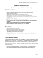
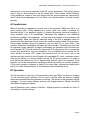
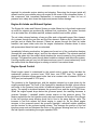
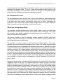
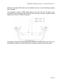
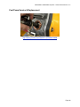
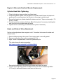
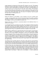
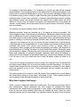
Aurora Portable Generator
Operation Manual
Models AGI6500DE & AGI6500SDE
AGI6500DE & AGI6500SDE Operator / Owners Manual Version 11.4
INTRODUCTION
Customer satisfaction is very important to us. If at anytime you have any questions
about this manual or require further help we encourage you to contact us by visiting our
website at www.AuroraGenerators.com and using our LIVE CHAT, sending an e-mail to
[email protected] or call us Toll Free at 1-877-510-6807
This manual is updated on a regular basis. Insure you have the latest version by
downloading it from Aurora Generators website.
Read all instructions and warnings before using this product.
This manual provides important information on proper operation & maintenance. Every
effort has been made to ensure the accuracy of this manual. These instructions are not
meant to cover every possible condition and situation that may occur. We reserve the
right to change this product and instructions at any time without prior-notice. The
information contained within this document is updated regularly on our website.
If there are any safety concerns, do not operate this product.
Do not return this product to the retailer - Contact customer service
for service or assistance.
If you experience a problem, have questions or need parts for this product, call
customer service at 1-877-510-6807 A copy of your sales receipt maybe required.
This generator is intended for residential consumer use only.
This generator is intended for residential emergency standby use only. Air cooled
generators cannot be run full time and are not manufactured for commercial use.
Page 2
AGI6500DE & AGI6500SDE Operator / Owners Manual Version 11.4
SAFETY INFORMATION
(For safe operation please follow the instructions strictly)
Risk of fire and explosion
•
•
•
•
•
•
•
•
•
•
Never use gasoline in a diesel engine or fire and explosion may result.
Always handle fuel outdoors
Identify the correct fuel type and model before refueling.
Always wipe off any spilled fuel and oil before using your generator.
Keep generator away from any flammable products and at least 3 feet clearance
on every side.
Never use it in an enclosure
Refuel in a well-ventilated area with the engine stopped.
Do not fill the fuel tank above the upper limit line. Diesel fuel may expand during
operation.
Empty the fuel tank before storing or transporting this generator.
Before transporting, turn the fuel valve to the “OFF” position.
Acid warning
•
•
•
•
•
Be careful when using any battery
Batteries will exhaust hydrogen while charging.
Only charge a battery in a well ventilated place
Keep away from open flame, heat or spark
Avoid spilled battery acid. If contact with skin is made, wash immediately with
water.
Carbon monoxide warning
Carbon monoxide poisoning occurs after the inhalation of carbon monoxide gas. Carbon
monoxide (CO) is a product of combustion of organic matter under conditions of
restricted oxygen supply, which prevents complete oxidation to carbon dioxide (CO2).
Carbon monoxide is colorless, odorless, tasteless, and non-irritating, making it difficult
for people to detect.
• Do not run the generator indoors, in confined spaces or in unventilated areas.
• The carbon monoxide gas produced by gas and diesel engines can kill you.
Page 3
AGI6500DE & AGI6500SDE Operator / Owners Manual Version 11.4
Electrical Shock Warning
• Electricity can kill you.
• Installation should be preformed by a certified electrician. Improper installation can
result in electrical shock and death.
• Follow all electrical safety code for your area. Consult an electrical safety inspector
or electrician.
• Do NOT hook up any generator to a buildings electrical system without the proper
use and installation of a transfer switch installed by a qualified electrician.
• Keep the generator dry.
• To reduce the risk of electrical shock do not use it in the rain or snow. Your
generator should be protected from the elements
• Do not allow children or non-qualified persons to operate this generator.
Operator Responsibility
•
•
•
•
Know how to stop the generator quickly in case of emergency
Understand the proper operation and maintenance procedure before using it
Be sure anyone using the generator receive proper instruction
Keep away from children and animals
Connections to a building electrical system
Connections for standby power to a building's electrical system must be made by a
qualified electrician. The connection must isolate the generator power from utility power,
and must comply with all applicable laws and electrical codes. A CSA or UL approved
transfer switch is recommended. Improper connections to a building's electrical system
can allow electrical current from the generator to back feed into the utility lines. Such
back feed may electrocute utility company workers or others who contact the lines
during a power outage. When utility power is restored, the generator may explode, burn,
or cause fires in the building's electrical system. You are required to check local
regulations for proper registration, use and procedures for generators. The ground
terminal can be used to earth the generator or bond the frame of the generator to the
frame of a vehicle, but only if it is required by local law or electrical code. Before using
the ground terminal consult a qualified electrician or electrical inspector for regulations
in your area.
Generator ground circuits
Bonding the neutral wire to ground is required on some construction sites. Industrial
Generators provide neutral bonding. Some models are neutral bonded which allows the
industrial generator to pass Occupational Safety and Health Administration job site
inspections. Portable generators have a system ground that connects generator frame
Page 4
AGI6500DE & AGI6500SDE Operator / Owners Manual Version 11.4
components to the ground terminals in the AC output receptacles. The system ground
may or may not be connected to the AC neutral wire. This is called "neutral bonding"
Local regulations, codes or laws may require that the ground system be connected to
the AC neutral wire depending on its use. Most of our products have a "neutral bonded"
grounds.
AC Applications
Before connecting an appliance or power cord to the generator: Make sure that it is in
good working order. Faulty appliances or power cords can create a potential for
electrical shock. If an appliance begins to operate abnormally, becomes sluggish or
stops suddenly, turn it off immediately. Disconnect the appliance, and determine
whether the problem is the appliance, or if the rated load capacity of the generator has
been exceeded. Make sure that the electrical rating of the tool or appliance does not
exceed that of the generator. Never exceed the maximum power rating of the generator.
Power levels between rated and maximum may be used for no more than a few
minutes. Substantial overloading will open the circuit breaker. Exceeding the time limit
for maximum power operation or slightly overloading the generator may not switch the
circuit breaker OFF, but will shorten the service life of the generator. Do not exceed the
current limit specified for any one receptacle. If an overloaded circuit causes the AC
circuit breaker to switch OFF, reduce the electrical load on the circuit, wait a few
minutes and then reset the circuit breaker. An overloaded DC circuit, excessive current
draw by the battery, or a wiring problem will trip the DC circuit protector. It is either a
push button that extends out or is a physical fuse that will have to be replaced. If this
happens, wait a few minutes before pushing in the circuit protector to resume operation.
If the circuit protector continues to switch off or blow fuses, discontinue charging and
check your load. Empty batteries, or low batteries may overload the circuit.
DC Operation
The DC terminals on the front of the generator panel may ONLY be used for charging
12 volt automotive-type batteries. Do not start a vehicle while the battery charging
cables are connected and the generator is running. The vehicle or the generator may be
damaged. It is not a smart charger and can over charge batteries. Caution should be
used when charging any battery.
Aurora Generators use a charge controller / voltage regulator to maintain its down 12
volt battery for electric starting.
Page 5
AGI6500DE & AGI6500SDE Operator / Owners Manual Version 11.4
GENERATOR OVERVIEW
The main difference between the Aurora open frame generator and enclosed silenced
type is the noise it produces. Both models use the same engine and alternator with
some minor differences.
The enclosed silent diesel generator uses two much larger mufflers and a separate
diesel oxidation catalyst ( also known as a catalytic converter) The enclosed diesel
generator does not use a manual recoil starter. In place of the manual recoil starter is a
larger flywheel with fins used to force air through the enclosure, around the engine and
exhaust system to keep it running at normal temperatures. The enclosed silent type
generator runs much quieter and comes with a remote control to start and stop it.
Common Features
•
•
•
•
•
•
•
•
•
•
EPA Approved 11 HP Diesel 186F Type Single Cylinder Engine 3600 RPM
FCC Approved Remote Control Transmitter ( Silent Diesel Only )
ETL Certified to CSA Standard 22.2 No 100
Self Excited 2 Pole Singe Phase Alternator
12 volt, 120 and 240 volt output
User Adjustable Automatic Voltage Regulator
Electric Start (silent version includes remote control start)
Battery Included in both models
Automatic Low Oil Shut Down
Digital Hour, Voltage and Frequency Meter
Page 6
AGI6500DE & AGI6500SDE Operator / Owners Manual Version 11.4
Page 7
AGI6500DE & AGI6500SDE Operator / Owners Manual Version 11.4
Page 8
AGI6500DE & AGI6500SDE Operator / Owners Manual Version 11.4
Technical Specifications
Generator Model
AGI6500DE & AGI6500SDE
Certifications
2010 / 2011 EPA
ETL Approved to CSA 22.2 No.100
Engine Model
Aurora 186F
Engine Type
Air cooled single cylinder, 4 stroke, direct injection diesel.
Cooling System
Forced air cooled
Engine Speed
3600 RPM ( 60 Hz )
3000 RPM ( 50 Hz )
Engine Displacement
418 cc
Engine Bore
86 x 72
Engine Power
11 HP
Engine Lube Oil
Synthetic 15W40 for diesel motors only.
Oil Lube Capacity
1.65 L
Engine Lube Oil Pump
Forced
Engine Run Time
12 Hours / 2.9 Gallons under 75% load
Cold Start Heater
Installed on air intake
Decompression Valve
Installed on engine
Fuel Type
Diesel Ultra Low Sulfur Automotive Fuel Only.
Max Height Above Sea Level
1000 Meters / 3280 feet
Generator Type
Self Excited two poll single phase
Voltage Regulator
User adjustable automatic voltage regulator
Generator Insulation
Class F
Power Factor
1
Rated Frequency
60 Hz.
Rated Output
120 Volts @ 41.6 amps
240 Volts @ 28.8 amps
Page 9
AGI6500DE & AGI6500SDE Operator / Owners Manual Version 11.4
PRINCIPLES OF OPERATION
Fuel System
The Generator Fuel System provides filtered and pressurized diesel fuel to the diesel
engine. It consists of a fuel tank with removable fuel fill strainer, fuel lines, fuel filter, fuel
injection pump, and a fuel injector.
The diesel fuel is stored in a fuel tank. The tank features a plastic mesh strainer in the
fill neck opening and a fuel tank drain valve. The fuel tank supplies fuel via a flexible
tube to the fuel filter. The fuel filter removes impurities and water from the diesel fuel
before it reaches the diesel engine. The fuel filter is made up of a clear bowl and filter
head with a throw-away paper filter. The fuel filter also includes a fuel shutoff valve and
some version include bleed screws for removing air trapped in the fuel system. Another
flexible tube connects the fuel filter and the fuel injection pump (part of the diesel
engine).
With the engine cranking or running, the fuel flow is controlled by a mechanical
governor (part of the diesel engine) and the fuel injection pump. The fuel injection pump
pressurizes the fuel and transfers it to the fuel injector. Fuel is sprayed by the injector
into the engine combustion chamber where it is mixed with air and ignited. (This video
explains how it works) The fuel that is not burned by the engine is returned to the
generator set fuel tank via an excess fuel return line on the fuel injector. The returning
fuel is used to lubricate the injector and keep it cool. Any derbies in the fuel system may
cause the fuel injector to stick open or not close completely. This dripping of fuel will
result in poor combustion and engine operation.
The diesel engine is shutdown by the operator depressing the engine STOP lever which
places the fuel injection pump control rack in the no fuel position. Stop the fuel and you
stop the engine.
For models that can be shut off by an electric switch, an electric
solenoid pulls a cable that releases the same RUN/STOP lever. The drawbacks are
that you have to reset this RUN/STOP lever back to the run position the next time you
want to use the generator.
Alternatively some models use an electric fuel switch to stop the fuel from reaching the
fuel pump. The switch is an electric magnet that pulls open a spring loaded plunger
with rubber stopper at the end of it. When open, the engine can run normally. When
closed it starves it of fuel causing it to shut down.
Low oil pressure detected or the engine starter switch turned to the off position can
trigger either one of these devices to shut down the engine starving it of fuel.
Some fuels can damage the rubber fuel stopper inside the electric fuel switch causing it
to stick and not open. Overheating or intermittent electrical connection may cause the
electric magnet release or fail resulting in a engine that will not start or is starved of
enough fuel that under load it fails to run correctly. This electric fuel switch is only
Page 10
AGI6500DE & AGI6500SDE Operator / Owners Manual Version 11.4
required for automatic engine starting and stopping. Removing the plunger inside will
defeat it and let you continue using your engine in the event of this component failure. If
this component fails immediate replacement is recommended in order for low oil
pressure auto safety shut down the engine and prevent further damage.
Engine Air Intake and Exhaust System
The Engine Air Intake and Exhaust System provides filtered air to the diesel engine and
an outlet for exhaust gas produced by air/diesel fuel combustion. The system consists
of an air intake filter, air intake manifold, exhaust manifold, and muffler system.
The air intake cleaner features a foam pre-filter and a disposable paper filter element.
Air is drawn through the pre-filter and the filter element. Airborne dirt is trapped in the
pre-filter and air intake filter element. Filtered air passes through the filter, air intake
manifold, and open intake valve into the engine combustion chamber where it mixes
with pressurized diesel fuel and is combusted.
Immediately following combustion, hot gases are forced out of the combustion chamber
(through the open exhaust valve), and into the exhaust manifold. The exhaust manifold
passes the gases into the muffler which deadens the sound created by the combustion
process. The gases then pass through diesel oxidation catalysts and the muffler system.
A muffler system can get very hot and personnel may occur if users inadvertently touch
the muffler while the diesel engine is running or before it has cooled down.
Engine Speed Control
Diesel engine speed is maintained by the speed control system which includes the
mechanical governor, governor lever, RUN lever, and STOP lever. The system is
designed to maintain engine speed under load at a constant rate of between 3570 and
3630 rpm (no load speed of 3750 rpm).
The governor is the flyweight-type, with the weights mounted on a gear driven by the
engine camshaft gear. The force of the flyweights is transferred through a thrust sleeve
and collar to the governor lever which is balanced against the tension of the governor
spring. The spring is stretched between the governor lever and the engine RUN lever.
When the engine speed drops below the governed speed, the resulting decrease in
governor flyweight / camshaft rotation places tension on the governor spring. The
tension repositions the fuel injection pump rack and increases the stroke of the plunger
in the fuel injection pump allowing more fuel to flow to the pump delivery valve. The
increase in fuel flow causes the diesel engine to speed up. As the diesel engine
recovers to the governed speed, the governor flyweight / camshaft rotation stabilizes
and the tension on the governor spring relaxes. This changes the position of the fuel
injection pump rack and shortens the stroke of the plunger allowing less fuel to flow to
the fuel injectors maintaining the engine speed at 3600.
Page 11
AGI6500DE & AGI6500SDE Operator / Owners Manual Version 11.4
The governor control mechanism features two operator controlled levers. The diesel
engine RUN lever places tension on a spring attached to the governor lever. The
tension places the governor lever in a position to allow fuel flow to the fuel injector for
diesel engine start up and to allow the diesel engine to continue running after start up.
The diesel engine shutdown or STOP lever is operated by either depressing the red
STOP lever or by the low oil pressure shutdown system. When depressed, the lever
trips the RUN lever releasing the tension on the governor spring which places the
governor lever in a no fuel or stop position. This action shuts off fuel flow to the fuel
injector stopping the combustion process and shutting down the diesel engine
Engine Electrical Starting System
The diesel engine electrical starting system can be used to start the diesel engine
whenever there is a 12 VDC power source connected. Aurora generators have a battery
included with the generator that may already be connected. When the generator is
running, it recharges the battery. Electrical Starting will be required when starting the
diesel engine in extremely cold weather or as a backup to the manual starting system
found on the open frame type generators. The electrical system also provides a means
for warming diesel engine intake air which also helps to start the engine in cold weather.
The system consists a momentary contact switch located on the generator electrical
panel.
Starting the engine with the starter motor is possible when the operator places the start
switch in the START position, power is applied through the switch to the starter
solenoid. This energizes the coil in solenoid which pulls in the solenoid's plunger and
pushes the starter drive pinion attached to the plunger toward the engine flywheel. This
movement engages the starter pinion drive with the ring gear teeth on the diesel engine
flywheel. As the solenoid plunger pulls in, the power available at solenoid pin S is
applied via a jumper to the starter motor which rotates the starter pinion drive (part of
the starter motor) and turns over the flywheel engaged with the pinion drive to start the
diesel engine. Immediately after the diesel engine starts, the generator set operator
releases the START switch. This opens the solenoid-starter circuit causing the solenoid
plunger to release the starter pinion drive disengaging it from the engine flywheel ring
gear. At the same time, the starter motor is de-energized. The starter pinion will return to
its normal position as the starter motor slows to a stop.
When your generator is running, the battery is automatically kept charged. A charge
regulator is mounted on the side of the engine and gets its power from the generator. A
dead battery or very low charged battery can overload and damage the built in charger.
Never use a low charged or dead battery.
Engine Pre-Heating
Preheat Circuit. The diesel engine features one 12-VDC resistance-type heater located
in the engine air intake piping between the intake manifold and the air cleaner. The
Page 12
AGI6500DE & AGI6500SDE Operator / Owners Manual Version 11.4
heater warms the air intake piping and manifold in order to warm up the intake air during
attempted cold weather starts. To use it, toggle the momentary switch located on the
front panel. Press down on it and hold it for up to 20 seconds. It will power the glow
plug to heat it up. Release it and start your generator normally.
De Compression Lever
The de-compression leaver is often used to aid in cold starting or when starting using
the manual recoil starter. Pressing the decompression leaver causes the exhaust valve
to be held open and prevents compression during the up stroke. Eliminating the
compression cycle helps the operator create enough inertia and engine speed that
when compression is restored starting should be much easier.
Generator Voltage Regulation
The generator voltage regulation and output supply system senses the load being
drawn at the load terminals and adjusts the alternator output accordingly. The system
also monitors and adjusts generator set performance and provides power to the
electrical terminals and receptacles.
The system consists of the AC alternator, voltage regulator, ON-OFF load circuit
breaker, output load terminals, AC Volt Meter, Hour Counter, Frequency HERTZ meter
and voltage adjustment potentiometer.
The generator set output voltage is controlled by the voltage regulator. The voltage
regulator continuously senses the alternator output voltage. The voltage regulator reacts
to voltage variations by manipulating the alternator field current to maintain the output
voltage. The field current controlled by the voltage regulator is supplied by the alternator
excitation windings. The voltage regulator performs this function using three interactive
sub circuits: power input, load sensing, and DC output. The power input circuit draws
current from the AC generator exciter windings through the positive (+) field brushes at
A1 pin 3. The load sensing circuit monitors the current being drawn by the load at A1 pin
E1. As demand increases, the DC output circuit draws current from the power input
circuit, rectifies it to direct current, and reapplies it to the AC alternator (G2) field via A1
pins F+ and F-.
Starting the diesel engine automatically field flashes the AC alternator (G2) with residual
magnetism stored in the rotor. The residual magnetism induces voltage in the power
excitation windings at AC alternator (G2) pins + and 2. As the diesel engine speed
begins to increase toward its governed no load speed of 3750 rpm, the induced voltage
in the power excitation windings increases. The voltage regulator (A1) power input
circuit receives current from the power excitation windings via the positive (+) field
brushes at A1 pin 3. Whenever the voltage in the load sensing circuit matches the set
point, the current entering the voltage regulator (A1) at pin 3 is allowed to pass through
the power input circuit. Whenever the voltage entering the sensing circuit is lower than
the set point (indicating a load increase) the DC output circuit reacts by drawing current
Page 13
AGI6500DE & AGI6500SDE Operator / Owners Manual Version 11.4
from the power input circuit. This current is rectified to DC and reapplied via A1 pins F+
and F- to the AC alternator rotor brushes at G2 pins + and -. The application of direct
current to the rotor increases the field magnetism between the AC alternator stator and
rotor which in turn, increases the current measured across the alternator power
windings. The current measured at both the excitation and power windings will increase
until the voltage entering the voltage regulator (A1) load sensing circuit matches the set
point at which point, the alternator output stabilizes and the A1 DC output circuit stops
drawing current from the power input
circuit.
The voltage regulator set point can be changed by adjusting the VOLTAGE ADJ.
potentiometer.
The generator set performance can be monitored by observing the AC VOLTS meter
and Hertz Frequency Meter. The VOLTS AC meter (M2) measures the voltage across
the power windings of the AC alternator and displays the value in VAC
from 0 to 300. The HERTZ frequency meter measures frequency across the power
windings in Hz from 45 to 65. The mains circuit breaker protects the VOLTS AC and
HERTZ frequency meters from a potential over current condition.
Low Oil Pressure Protection
The low oil pressure protection system shuts down the diesel engine in the event of low
oil pressure in order to protect the engine from further damage. The system consists of
a low oil pressure switch located in the engine block above the oil strainer, a low oil
pressure solenoid mounted in the control panel, and a cable connecting the low oil
pressure solenoid to the diesel engine STOP lever. The enclosed diesel generator does
not use a pressure solenoid, a electric fuel switch is use instead and is mounted on the
fuel pump.
Under normal operating conditions the low oil pressure sensor switch OPENS at 15 PSI
If a malfunction occurs in the lubrication system causing the oil pressure to drop below
the low oil pressure set point, the low oil pressure switch closes and completes a circuit
causing either the engine stop solenoid to release the engine STOP lever or if equipped,
closes shut the fuel valve located on the fuel pump. When this occurs the low oil
pressure light will illuminate on the generator control panel.
Page 14
AGI6500DE & AGI6500SDE Operator / Owners Manual Version 11.4
STARTING THE GENERATOR
Before you begin
Observe WARNINGS, CAUTIONS and INSTRUCTIONS contained in this manual and
on plates or decals located on the generator. Do not operate if there is any deficiencies
or irregularities or you do not fully understand the operation of this equipment and any
hazards.
Operator Preventive Maintenance Checks and Services
• Check load terminals, sockets and outlets for any irregularities or deficiencies.
• Check for any loose hardware, terminal, or fasteners. The starter battery terminals
must be tight.
• Insure proper grounding.
• Make sure main circuit breaker is in the OFF position
• Check air intake cover wing nut for security. Tighten if necessary
• Inspect fuel filter assembly for damage and security.
• Check fuel filter bowl for water or other contaminants. Inspect fuel system for loose
or missing fuel line clamps, damaged fuel lines, and leaking/damaged fuel tank.
Check for evidence of fuels leaks
• Check fuel level and if necessary, service fuel tank to red line on fuel strainer.
Ensure fuel tank fill neck strainer is not clogged or damaged.
• If you find any oil in a new generator, it is from factory testing. It must be removed,
engine flushed and replaced with new lube oil.
• Ensure generator set is level and check diesel engine lubricating oil level using oil
fill cap/dipstick. Add oil if required.
• Inspect the diesel engine and surrounding area for oil leaks.
• Inspect cooling fins and air intake slots in recoil starter cover for damage and
debris restricting air flow over and through cooling fins. Remove debris. Check
recoil starter assembly for damage and operation.
Page 15
AGI6500DE & AGI6500SDE Operator / Owners Manual Version 11.4
Electric Starting
1.
Ground generator. Never attempt to start the generator set if it is not properly
grounded. Failure to observe this warning could result in serious injury or death
by electrocution. Drive an eight-foot (or longer) ground rod into ground until
clamp on top of ground rod is just above surface. Connect a 6 AWG minimum to
the ground terminal on your generator.
2.
Switch main circuit breaker OFF (Never attempt to connect or disconnect load
cables while the generator set is running. Failure to observe this warning could
result in severe personal injury or death by electrocution.)
3. Connect load cables to load terminals
4. Perform the Preventive Maintenance Checks and Services
5. Ensure fuel shut off is in the OPEN position
6. Move the engine RUN lever to RUN position
7. Do not crank engine more that 10 seconds without allowing the starter to cool for
at least 15 seconds between attempted starts. Over cranking can damage the
starter. Turn the START switch clockwise to the START position and release
when the engine has started.
8. If the engine fails to start you can utilize the engine preheater and
decompression leaver.
9. If the engine fails to start repeat steps 6 to 7
10. If the engine still fails to start after two attempts refer to the troubleshooting
guide.
11. Once the engine is running, check any gauges to insure proper operating
conditions. Voltage and Frequency should be correct. Under normal conditions
allow diesel engine to warm up for five minutes before applying a load. If
necessary the load can be applied immediately.
12. Switch the mains circuit breaker to the ON position to apply a load.
Page 16
AGI6500DE & AGI6500SDE Operator / Owners Manual Version 11.4
STOPPING THE GENERATOR
1.
2.
3.
Remove the load from the generator by turning OFF the mains circuit breaker
Turn the starter key to the OFF position
If generator fails to shut off, press the red stop lever to release the throttle and
refer to the troubleshooting section of this manual.
A decompression lever on the engine helps the operator start the engine when it is
extremely cold, when the battery is low, or when bleeding the fuel system. Caution: The
decompression lever must never be used to shop the engine except in emergencies
such as a run away engine or throttle damage as serious damage can be done to the
exhaust valves.
Page 17
AGI6500DE & AGI6500SDE Operator / Owners Manual Version 11.4
INITIAL SETUP
Your generator has been run and load tested at the factory to insure it meets
specifications. A external fuel tank has been used and all the fuel that remains is in the
fuel filter and fuel lines. Most of the lube oil has also been removed. If you find any oil in
a new product, it must be flushed and replaced. Oil and fuel is considered hazardous
material. For shipping, most if not all fluids are removed. You must add lube oil and fuel
before you can begin to use your generator. The battery must be fully charged then
connected before using it and you must have read and understand the complete
instructions. If you are not sure of anything, call Aurora Generators at 1-877-510-6807
or email technical support at [email protected]
Engine Lube Oil
The main purpose of engine oils is to lubricate moving parts of the engine to reduce
friction and wear and tear by providing smoothing, trouble free performance for
increased length of time. In a diesel engine it also helps to seal the high-pressure
combustion gases inside the cylinders, to impede the corrosion of metal parts, to absorb
some of the harmful by-products of combustion, and to transfer heat from one part of
the engine to another. Combustion of rich air-fuel mixture during starting, idling and
warm up form deposits. These deposits in the form of varnish, sludge, soot and carbon,
interfere with proper engine operation. The engine oil keeps all the deposit forming
material in suspension and gets rid of them by oil filter, or draining out at proper
intervals.
Engine oil is stored in the oil pan or sump at the bottom of the engine. A pump forces
the oil through a filter and then through a series of passages and galleries to lubricate
the engine’s moving parts. The flow of also cools these parts. Rapidly moving engine
parts actually float on a thin film of oil and never make contact with one another. This is
called hydrodynamic lubrication and usually begins when an engine reaches the idle
speed. When the oil is cold or the engine has not been run for a long period of time, it
takes a while before oil reaches its normal operating pressure an flow. During this time
is when most engine wear occurs.
When possible, wait five minutes before applying a load to your generator.
ONLY use lube oil designed for diesel engines.
Regular lube oil used in gasoline engines is not designed to work with the much higher
temperatures diesel engines produce internally. Using regular lube motor oil will
damage your engine and void your warranty. The wrong lube oils also breaks down from
the higher level of sulfur and oxides the burning diesel engine produces. When in the
presence of water, sulfur acids cause corrosion of engine parts. Hence the need of
alkalinity reserve in the oil which is represented by its TBN or Total Base Number.
Page 18
AGI6500DE & AGI6500SDE Operator / Owners Manual Version 11.4
Generally, the higher TBN value more the alkalinity reserve or acid neutralizing capacity
the oil contains.
Your generator requires 15W40 diesel lube oil only. For the first 25 hours a non
synthetic lube oil is required. After the initial 25 hour break in process, synthetic diesel
engine lube oil 5w40 to 15w40 is required.
The engine is designed in such a way that it is difficult to overfill it and as you can see in
this illustration above oil should be filled until it reaches just below the oil filter neck.
Page 19
AGI6500DE & AGI6500SDE Operator / Owners Manual Version 11.4
Regardless of how little you may use your generator the oil on its own will break down
losing some of its properties in 3 months. The same applies to your vehicle. You must
replace it every 3 months. If you use your generator within that time, the oil should be
changed every 100 hours or earlier. There is nothing you can do that will add more life
to your engine then regular oil changes. This is very important and is the leading cause
of engine failure.
Add Diesel Fuel
Diesel fuel only should be used. The regular diesel fuel you find at the gas station used
for cars only. Not off road vehicles, farm or construction. Some Bio Diesels that are safe
for cars are also safe for your generator however there are many different types and we
can't guarantee the quality or that it will not damage your engine. While a diesel engine
can run on many different types of fuel such as vegetable oils and other bio diesels
some can clog the fuel filter, fuel injector and fuel pump. A grain of sand is all it takes to
plug a fuel injector! Do not use old fuel. Fuel does go bad over time. Diesel Fuel is also
used as a lubricant to lubricate the fuel pump, injector and fuel valves. Now with new
low sulfur fuels on the market the sulfur that used to give diesel fuel some of its
lubrication properties have been lost. For optimal performance we do suggest fuel
additives be used especially in cold climates. This topic is covered on another page in
more details.
Warnings
• Close all fuel valves
Page 20
AGI6500DE & AGI6500SDE Operator / Owners Manual Version 11.4
•
•
•
•
•
•
•
•
Insure when filling that no fuel is spilling or leaking for any hoses or filters.
When filling from oil drums, ensure that no dirt or water enters the fuel tank.
Contamination can cause serious fuel system problems.
Never over fill the fuel tank.
Filling should only be done in a well-ventilated area with the generator turned off.
Never refill while the generator is running. Spilled fuel can ignite on a hot surface.
Clean up all spills and ensure that area is dry before starting the generator.
Do not use old fuel
Under some fuel tanks is a fuel shut off valve. When filling or transporting your
generator it must be off. The valve should be in the open position when you are using
your generator. Some people forget to open it and either can't start the engine or cause
air to be sucked into the fuel pump if it can't get the fuel supply it requires. If your
generator has fuel filter make sure to check the fuel valve on it also. The valve on the
fuel filter assembly maybe the only one you have.
Page 21
AGI6500DE & AGI6500SDE Operator / Owners Manual Version 11.4
Priming and Bleeding the Fuel System.
http://www.youtube.com/watch?v=uQLkLtUdgh4&
Under normal conditions, the fuel system does not require priming. Certain conditions
may allow air into the fuel system such as running out of fuel. Once this occurs, the air
must be bled before the engine will start or run smoothly again.
The engine fuel pump can only pump fuel, it can't pump air. Air in the fuel lines will make
it impossible to start your engine. Air bubbles can also damage your fuel injector and will
cause rough engine operation since the fuel being delivered is not a consistent flow. If
there is some air in the fuel delivery system it may take up to 15 minutes to naturally be
purged through. The engine may not run normally during this time.
Note: Not all fuel filter assemblies have the bleed screws on the top. You my have to
remove the rubber fuel line from the fuel pump to achieve the same thing.
Warning - Hot fueling of generator sets while they are operating presents a safety
hazard and should not be attempted. Hot engine surfaces and sparks produced from
Page 22
AGI6500DE & AGI6500SDE Operator / Owners Manual Version 11.4
the engine and generator circuitry are possible sources of ignition. Failure to observe
this warning could result in severe personal injury or death.
1. Check that fuel tank has fuel and that fuel shutoff valve located on the
filter is positioned to ↓O (open).
2. Open two bleed screws at top of filter in the order listed below.
(a) Open left bleed screw to bleed air from tank-to-filter fuel line.
(b) Open right bleed screw to bleed air from filter to pump fuel line. It may
be necessary to squeeze line by hand to force air out of bleed screw.
3. When fuel flows freely and evenly out of bleed screws (without air
bubbles), tighten both bleed screws.
4. Loosen output fuel line fitting at fuel injection pump, place engine RUN
lever to RUN position, depress and hold decompression lever, and pull
recoil starter rope until fuel flows from around fuel line fitting (without air
bubbles). Tighten output fuel line. If you have an electric start version you
can crank the engine for short periods of time to do the same thing.
Page 23
AGI6500DE & AGI6500SDE Operator / Owners Manual Version 11.4
PREVENTIVE MAINTENANCE
CHECKS AND SERVICES
Within designated intervals, these checks are to be performed in the order listed.
M-Monthly Q-Quarterly S-Semi-annually A-Annually B-Bi-annually H-Hourly
Interval
Item
Item To Be
Inspected
Procedure
Generator should
not be used if
x
Diesel Engine
Check for loose, damaged, or
missing parts. Tighten loose
parts. Repair or replace damaged
or missing parts. Inspect
decompression lever for debris.
Clean if needed.
Engine parts are
loose, damaged,
or missing.
x
Starter
Battery
M
Q
S
A
B
H
Check battery terminals are
secure. Recharge battery if not
in use.
Primary and
Pre-filter Air
Filter
Elements
Inspect for clogged primary
(paper) air filter element. Clean
every 50 hours or as required, or
replace element if damaged.
Replace pre-filter (foam) element.
x
Ground
Terminal Lug
Check for damage or corrosion.
x
Control Panel
Check for any loose hardware or
corrosion.
Engine Lube
System
Change diesel engine oil after the
first 20 hours of operation and
then after every 100 hours. (1)
Remove diesel engine oil drain
plug and collect oil in an
appropriate chemical resistant
container for disposition/disposal.
Remove, clean, and install oil
strainer. Add proper lube oil.
15W40 Synthetic
50
20
(1st
Time)
100
100
50
1000
Fuel Filter
Element
Air cleaner
element is
clogged or
damaged.
Replace fuel filter element.
Inspect gaskets for damage
Spark Arrestor
Check for damaged, missing or
corroded spark arrestor if
present.
Alternator
Brushes
Wires and
Holders
Check for worn alternator
brushes. Length must be a
minimum of 0.5 in. (1.3 cm).
Check for damaged or missing
brush caps, wires, and holders.
Alternator
brushes worn.
Damaged or
missing brush
caps, wires, and
holders
Page 24
AGI6500DE & AGI6500SDE Operator / Owners Manual Version 11.4
20
(1st
Time)
500
500
20
(1st
Time)
200
1000
2000
Intake and
Exhaust
Valves
Adjust valve head clearance after
the first 20 hours of operation
and then every 500 hours.
Primary and
Prefilter, Air
Filter
Elements
Replace air filter elements
Cylinder Head
Nuts
Fuel Injector
Fuel Injection
Pump
Check after first 20 hours of
operation and then every 500
hours. Check for loose head
nuts. Torque cylinder head nuts.
Head nuts are
loose.
Replace every 1,000 hours.
Replace fuel injection pump.
Generator
Set, Engine/
Alternator,
and Control
Panel
Check for damage, corrosion,
missing, or loose attaching
hardware
Damaged,
corroded,
missing, or loose
hardware
Fuel Lines
Inspect for breaks and/or
damage. Replace damaged fuel
lines.
Fuel lines leak or
show signs
of wear or
damage
x
Fuel Tank
Check for damaged, corroded, or
missing fuel fill strainer, tank cap
lug, and retaining rope.
Damaged,
corroded, or
missing
components
x
Alternator
Check for damaged flexible
sleeve coupling and flexible
flange couplings
Damaged
alternator
coupling
components
Control Panel
External
Check for damaged, corroded, or
missing convenience receptacle
and cover (MEP-531A); LOP
engine shutdown cable grommet
and cable guide; and slave
receptacle.
Damaged,
corroded, or
missing control
panel
components.
x
Control Panel
(Internal)
Check for any lose wiring,
damaged or bruned wires and
insulation on all electrical leads
and harnesses. Ensure that
protective cover on rear of
instrument panel is secure.
Damaged control
panel
components
x
Electrical
Outlets
Check for damaged or corroded
load terminals, electrical outlets,
plugs and any fasteners.
Damaged or
corroded load
terminals or
receptacles
x
x
x
Page 25
AGI6500DE & AGI6500SDE Operator / Owners Manual Version 11.4
x
Generator Set
Check ground strap for damage.
Damaged ground
strap.
x
Low Oil
Pressure
(LOP) Engine
Shutdown
Cable
Check for damaged push-pull
cable and tube. Check cable
adjustment.
Damaged or
misadjusted
LOP engine
shutdown cable
Check for damaged or missing
tubing and protective boot;
damaged or burned wires and
insulation.
Damaged air
preheater lead
Air Preheater
Lead
x
Engine Wiring
Harness
Check for damaged, missing,
corroded clamps; damaged or
missing tubing and
protective boot; and burned
insulation.
Alternator
Wiring
Harness
Check for damaged, missing,
corroded clamps; damaged or
missing tubing and protective
boot; and burned insulation
Resilent
Mounts
Replace resilient mounts after
2000 hours
x
Frame
Check for damage and corrosion.
Damaged or
corroded frame
x
Fuel System
Check for damaged or corroded
fuel tank brackets and guard.
Damaged or
corroded
components.
x
Engine/
Alternator
Check for damaged, corroded
alternator guard, brackets,
engine mounting bracket, and
fuel filter stiffener
Damaged or
corroded
components.
x
Air Intake
System
Check for damaged or corroded
air filter plate and air filter cover.
Damaged or
corroded air
intake
components
Exhaust
System
Check for damaged or corroded
muffler and shroud; damaged or
missing grommet; damaged
muffler blanket; damaged,
missing, or corroded retaining
wire.
Damaged or
corroded
exhaust system
components
Alternator
Check for damaged engine
adapter and damaged or
corroded support bracket
Damaged or
corroded
alternator
components
x
x
2000
x
x
Damaged,
missing, or
corroded
generator wiring
harness
components
Page 26
AGI6500DE & AGI6500SDE Operator / Owners Manual Version 11.4
DETAILED PREVENTIVE MAINTENANCE
PROCEDURES
Fuel Filter Replacement
Removal
1. Shut down the generator set
2. Close the fuel shut off valve
3. Unscrew the retaining ring and separate the bowl and head using care not to spill
diesel fuel trapped in the bowl. Then pour diesel fuel into suitable container
4. Remove and discard fuel filter element and gasket
Installation
1.
2.
3.
4.
5.
Clean bowl with clean cloth
Install new fuel filter element in bowl.
Lubricate new gasket with clean diesel fuel and seat in land of bowl
Assemble bowl to head and hand-tighten retaining ring
Prime and bleed the fuel system
Page 27
AGI6500DE & AGI6500SDE Operator / Owners Manual Version 11.4
Air Filter Element Replacement.
Removal
1.
2.
3.
4.
5.
6.
Shut down the generator set
Remove 4 nuts securing metal cover on the silent diesel generator to expose the
air filter assembly inside the enclosure.
Remove the wing nut
Remove the pre filter element
Remove the paper element
If necessary, remove gaskets from mounting plate and cover. Clean adhesive
residue from surfaces
Inspecting and Cleaning
1.
2.
3.
4.
5.
Inspect cover for cleanliness, cracks and other damage. Clean cover with mild
soap and water.
Inspect filter element for cleanliness, dents, and crushed corrugations
Replace damaged parts.
Replace filter element if dirty
Replace pre-filter.
Installation
1.
2.
3.
4.
5.
If removed, install new gaskets on mounting plate and cover
Soak new pre-filter in clean engine oil and squeeze out ALL
Install pre-filter over filter element. Pre-filter should fit snugly over filter element
Position filter element with pre-filter and cover on mounting plate
Install wing nut.
Page 28
AGI6500DE & AGI6500SDE Operator / Owners Manual Version 11.4
Oil Filter Replacement
This video shows the oil filter service on a disassembled engine for reference only.
There is no need to disassemble the engine.
http://www.youtube.com/watch?v=YZ0p8hVF7D4&
1. Remove oil filter retainer screw
2. Twist or pull of oil filter
3. Rinse off in soap and water and let dry.
4. Inspect rubber o-ring and replace if necessary.
5. Lubricate o-ring before replacing.
6. Insure oil filter in inserted all the way into engine block and o-ring is not pinched.
This video shows oil filter replacement on a disassembled engine. There is no need to
disassemble your engine it is for educational purposes only.
Page 29
AGI6500DE & AGI6500SDE Operator / Owners Manual Version 11.4
Fuel Pump Service & Replacement
http://www.youtube.com/watch?v=a1ZrAAYGt40&
Page 30
AGI6500DE & AGI6500SDE Operator / Owners Manual Version 11.4
Fuel Injector Replacement.
Removal
1.
2.
3.
Shut down generator set.
Disconnect pressure and return fuel lines from fuel injector.
Remove nuts and retainer from cylinder head.
4.
CAUTION To prevent damage to nozzle tip, wrap fuel injector in a clean cloth
after removal. Do not place unprotected nozzle tip directly on dirty surface.
Pull fuel injector straight out of cylinder head, wrap in clean cloth, and remove
spacer and gasket. If gasket (black plastic) remains in cylinder head, use a bolt
(5/16 in. diameter) that will thread into gasket to remove.
Inspection
1.
2.
Inspect injector for nicks, cracks, scoring, corrosion, and other damage.
Inspect nozzle tip for carbon deposits. Carefully clean deposits from nozzle body
and clean nozzle injection ports with 0.019 in. diameter wire
http://www.youtube.com/watch?v=jq6_bY5zfl8&
Installation
1.
2.
3.
4.
Clean fuel injector sleeve surface in cylinder head.
Install new gasket, spacer, and fuel injector in cylinder head. Ensure fuel injector
is positioned to connect pressure fuel line prior to securing in cylinder head.
Secure fuel injector in cylinder head with retainer and nuts. Torque nuts evenly to
7-9 lbs-ft (9-12 Nm).
Connect pressure and return fuel lines. Bleed fuel system if necessary
Page 31
AGI6500DE & AGI6500SDE Operator / Owners Manual Version 11.4
Engine & Alternator Resilient Mounts Replacement.
Cylinder Head Nuts Tightening.
1. Clean fuel injector sleeve surface in cylinder head.
2. Install new gasket, spacer, and fuel injector in cylinder head. Ensure fuel injector is
positioned to connect pressure fuel line prior to securing in cylinder head.
3. Secure fuel injector in cylinder head with retainer and nuts. Torque nuts evenly to 7-9
lbs-ft (9-12 Nm).
4. Connect pressure and return fuel lines. Bleed fuel system if necessary, Install gasket
and valve cover on cylinder head with bolts.
5. Tighten fuel line connecting nut and bleed fuel system if necessary
Intake and Exhaust Valve Adjustment.
Perform valve adjustment when engine is cold. Procedure is the same for intake and
exhaust valve.
1. Remove bolts securing valve cover. Then remove valve cover with gasket.
2. Remove cooling fan cover, refer to paragraph 4.53.b.
3. Align T mark on flywheel with V notch on cylinder body fin
This video shows the above procedure.
http://www.youtube.com/watch?v=J64VghmSsBc&
Ensure both valves are fully closed (both rocker arms have free play).
4. Loosen nut for adjusting screw and adjust screw until correct clearance [0.006 in.
(0.15 mm)] is achieved between rocker arm and valve cap
Page 32
AGI6500DE & AGI6500SDE Operator / Owners Manual Version 11.4
Aurora 186F Diesel Engine Specifications
Valve timing, initial angle of fuel delivery and valve clearances in
degrees.
Intake Valve Open
BTDC 13°
Intake Valve Close
ATDC 52°
Exhaust Valve Open
BBDC 57°
Exhaust Valve Close
ABDC 8.5°
Initial angle of fuel delivery
22° ± 1°
Intake valve clearances
0.10-0.15 mm cold
Exhaust valve clearances
0.10-0.15 mm cold
Injection Pump Pressure
19.6 ± 0.49 (200 ± 5) MPa(kgf/cm²)
Torque Specifications in SI units Newton Meters
Connecting Rod Nut
40-45
Cylinder Head Nut
55-60
Flywheel Nut
120-140
Fuel Injector Nozzle retainer nut
12 - 120
Rocker Support Bolt
25 - 30
All Standard M8 Bolts
20 - 30
All Standard M6 Bolts
15 - 20
Note: adjustments should be checked a second time after a short test period.
Page 33
AGI6500DE & AGI6500SDE Operator / Owners Manual Version 11.4
The Break In Period
The diesel engine must be broken-in, avoiding heavy loads (no greater than 75%), for a
period of twenty (25) hours to ensure proper operation of the generator set. After the
initial break-in period, engine lubricating oil must be changed, cylinder head nuts torque
must be checked, and intake and exhaust valve clearances must be checked and
adjusted.
Current technology provides the means of manufacturing engine parts with
unimaginable precision however they still far short of achieving the near perfect fit that a
proper break-in will provide. Break-in, is the allowance of the machined parts in the
engine engine to conform to each other. This conforming or mating specifically of the
ring and cylinder surfaces is the ultimate goal of a proper break-in. Mating these two
specific parts will produce a very tight seal in each cylinder. A tight seal is very important
because of the intense pressure diesel engines operate under. Mating helps prevent the
escape of unburned fuel and pressurized gasses into the crankcase, while further
preventing crankcase oil from entering the cylinder above the top compression ring. The
blow by also causes a loss of pressure and results in lack of power.
It is normal to find metal shavings trapped in your oil filter during this break in process.
Clean your oil filter normally.
Friction causes heat and until the break in occurs extra heat and most of the ware and
tear will happen during this period. Break in your engine before using it! Don't forget oil
will become contaminated faster because of combustion blow by fumes and metal that
is ground away during the mating process. The oil should be changed at at the first 25
hours. This is an important time for an engine. You should not subject the engine to
significant loading for the first 25 hours or more however some load IS desirable since
the heat and friction is also needed for the break in to occur. Excessive heat will burn oil
and cause it to harden leaving an enamel like residue on the cylinder wall, commonly
known as oil glazing and prevents the mating from occurring so small gaps between
rings and cylinder surfaces will never seal. The same applies to use synthetic oil during
the break in period. It will also prevent break in from happening. Only use synthetic oil
after the break in period. A moderate loading is the key to a proper break in. 1/2 the
rated power may be ideal. While some manuals suggest decreasing the RPM it is not
easy to do on generator motors since they have a fixed run or stop position that locks
into place on the throttle. If you can, secure it for this process for a break in period so
are running it at half the RPM you will benefit from it in the long run. Obviously you can
not use the generator until the normal speed is restored.
Improper Generator Use - Wet Stacking
"Wet Stacking" happens when a diesel engine operates below the rated output level
the engine starts over-fuel or "wet stack". Diesel engines are designed to operate with a
load and operate more efficiently in the 70 to 80% range of rated output. When a diesel
Page 34
AGI6500DE & AGI6500SDE Operator / Owners Manual Version 11.4
engine operates for a long period of time below 40% it begins to over fuel. This happens
because the injection tips begins to carbonize and disrupt the fuel spray pattern. The
only way to correct a diesel engine if it has begun to wet stack is to load the engine for a
couple of hours to burn off the excess fuel and clean up the engine. Diesel generator
sets with electronically controlled engines or advance emission systems are less likely
to wet stack. But all diesel engines will wet stack unfortunately, if operated for long
periods of time below rated levels. This is the reason it is important to get the proper
size and design of a diesel generator set.
Cold Weather Usage
Diesel fuel thickens in cold weather. It has a tendency to gel as it contains some
naturally occurring paraffin (wax) and as the temperature drops, this paraffin crystallizes
and affects the fluidity of the fuel and may cause hard starting and eventually lead to
filter plugging. You can use a fuel additive to prevent this.
Regular diesel fuel is winterized or seasonally adjusted at the distributor before it is
delivered to the pumps.
In cold weather fuel does not vaporize very well in the combustion chamber this makes
staring difficult. Modern diesel engines designed for cold weather use a pre heater and
glow plugs. Glow plugs are heating elements that work on a timed circuit or are
manually activated just before the engine is started. The colder it gets, the longer those
glow plugs need to stay on to preheat the combustion chamber for a smooth start.
Batteries that are weak may not crank the starter motor fast enough or long enough to
start a cold engine. As the temperature goes down, so does battery capacity. A battery
that has all of its power available at 80 degrees F will have only about 46% available
power at 0 degrees F. Plus, the engine will be 2.5 times harder to start at 0 degrees due
to thicker oil and resistance to movement of internal moving parts. In effect, an engine is
about five times harder to start at 0 degrees F than at 80 degrees F. Test weak or
suspicious batteries under load before cold weather to help eliminate potential problems
during busy times. If batteries need replacement, always replace with a battery equal to
the original battery.
Two different types of preheat elements seen after air filter has been removed. Before
starting heater gets red hot warming up air.. Seconds later when the starter kicks in the
generator pulls in this heated hear causing the diesel fuel to vaporize and ignite easier.
If you can press and hold the decompression lever a second while cranking and let go,
it will also help in the cold starting process. Use glow plugs or block heaters on the
engine for cold weather starts. Glow plugs heat the internal combustion chamber area
or preheat the air intake to suitable temperatures for combustion. Otherwise, cold fuel
sprayed into the chamber and onto the glow plugs can gel and adhere to these parts.
Hard starting and inefficient combustion occur with potential for damage to plugs and
cylinder heads. Use Number 1 diesel fuel in cold weather. It is more volatile than
Page 35
AGI6500DE & AGI6500SDE Operator / Owners Manual Version 11.4
Number 2 fuel and ignites more readily under cold conditions. Keep the fuel tank full to
prevent condensation inside the tank.
Water from condensation can freeze and plug fuel lines from the tank to the engine. Add
winter diesel fuel additive to the fuel to lower the possibility of gelling and improve
starting. Store generators inside tool sheds, barns, garages or other suitable locations
that are heated or warmer than outside temperatures. Only a few degrees warmer
temperature can make starting faster and easier. The warmer the battery is, the more
power it can provide to the starter motor to crank the engine. The warmer the engine oil
is, the thinner it will be and have less resistance to moving engine parts. Make sure you
are using the proper viscosity oil recommended for your engine for cold temperatures. If
you cannot store engines inside or in a heated area, install a block heater on the
engine. To save time and electricity, put the block heater on an electrical timer set to
come on a couple of hours before you plan to start the generator. After starting the
generator on a cold day, allow the engine to warm up a few minutes before putting it
under load. Proper engine operation temperatures assure more efficient fuel
combustion and may prevent damage to cold engine parts. Engine oil flows more
readily at operating temperatures and allows proper lubrication of engine parts and
areas.
Tips, Tricks and Things You Should Know.
Batteries
Generator batteries are often required to be float charged for long periods of time and
must be able to deliver high current when called upon. Generator batteries are often
sealed and maintenance free. Lead Acid batteries are often used however because the
content is an acid it is considered a hazardous material and often can not be shipped. If
your generator comes with a dry battery then you may be required to get it filled at Napa
Auto Parts for example the charge is minimal. Most generators sold here come with
sealed maintenance free batteries and do not need to be filled.
A lead-acid battery is composed of a series of plates immerse in a solution of sulfuric
acid. Each plate consists of a grid upon which is attached the active material (lead
dioxide on the negative plates, pure lead on the positive plates.) All of the negative
plates are connected together, as are all of the positive plates. When the battery is
under load and being discharged, acid from the electrolyte combines with the active
plate material. This releases energy and converts the plate material to lead sulfate. The
electrolyte become less acidic in the process.When a battery is recharged, the opposite
occurs: the lead sulfate reverts back to active material, and the electrolyte becomes
more acidic with a higher specific gravity.
Page 36
AGI6500DE & AGI6500SDE Operator / Owners Manual Version 11.4
To recharge a lead-acid battery, it is necessary to convert the lead sulfate material
which attaches to the discharged areas of the plates back to active plate material. If the
battery has not remained discharged for long or has only been discharged slightly, this
is a relatively easy process. However, when the battery has remained discharged for an
extended period or has been subjected to repeated deep-discharges without charging
fully between cycles, the sulfate material can harden into crystals which are more
difficult to convert. Until the sulfate is converted, the sulfated portions of the plates are
useless, and the battery can accept and hold only a partial charge. Eventually, sulfating
can ruin a battery.
The number one cause of battery failure is Sulfation
Whenever possible, bring any batteries up to full charge as slowly as possible. This
slow charging process is also known as equalization. Equalization allows the electrolyte
time to diffuse into the less accessible areas of the plate grid and convert those areas
from lead sulfate to active plate material. Infrequently-used or stored batteries are also
prone to sulfating if not kept fully-charged between uses. A battery loses approximately
1 percent of its charge per day (up to 2 percent in hotter climates) due to self-discharge.
If self-discharge is not compensated for, a stored battery can become sulfated and will
eventually be ruined. The second most common cause of battery failure is
overcharging. Many chargers on the market will damage your battery if left attached for
extended periods by "boiling" the water out of the electrolyte solution. Eventually, water
loss will destroy a battery. Checking the electrolyte level in a battery and adding distilled
water when necessary is extremely important, especially when using fast chargers or
many of the trickle chargers on the market Maybe buy a small trickle charger and leave
it on full time or hook up a small solar cell to keep the battery topped up when not in
use.
If you plan on storing your generator and not using it for a period if time it is advised that
you keep a small charger on it to prevent the battery from self discharging. You can buy
a small trickle charger from an automotive store and leaving it hooked up to your battery
when the generator is not in use. * Deep discharges are the number one cause of
battery failure.
The starter needs a lot of power to crank the engine. Slow cranking from a weak battery
will cause difficult staring or even make it impossible to start. Slow cranking results in
low compression and less heat necessary to ignite diesel fuel.
Why diesel engines last longer.
When it comes to generators diesel wins hands down. The engines are simple, there is
less maintenance. Diesel generators are built tougher to withstand the higher
compression ratio diesel burns at compared to a gas engine. Less maintenance means
more up time and more reliability when they are needed the most. There are many
technical reasons why to chose diesel over gasoline however the point of this document
Page 37
AGI6500DE & AGI6500SDE Operator / Owners Manual Version 11.4
is to help identify some important things necessary to truly befit from diesel and insure
your generator continues to run long after its equivalent gasoline generator has died.
Diesel engines operate at twice the compression ratio of gasoline engines; create
greater internal pressures and heat. Components are made to closer tolerances,
therefore are more easily damaged by dirt, corrosion improper fuel and lubricants.
Diesel injectors are expensive precision parts that handle fuel pressures as high as
137,900 kPa. Using correct diesel fuel is essential because it not only runs the engine,
but also lubricates and cools the fuel pump, injectors and spray tip. Dripping or leaking
injectors can cause rough engine operation, destructive unbalanced cylinder
temperatures, crankcase oil dilution and incomplete combustion.
Because of diesel fuel’s acid content, combustion byproducts are more corrosive.
Greater diesel heat also converts combustion byproducts to varnish inside the engine
more rapidly.
Dirt and water by passing fuel filters can badly score fuel pump and injectors, requiring
replacement. Rust can cause sticking in pump pressure regulator valves. Water in fuel
can also cause hard starting, uneven running and frequent stalling. Because diesel
engines breathe more air per hour than gasoline engines, air leaks through cracks,
loose connections or holes in flexible hoses can cause serious and expensive engine
damage.
Clogged air filters reduce power. Diesel engines make more use of oil as coolant
because of greater heat and pressure. For example, the oil cools piston undersides.
Improperly or inadequately filtered oil can cause scoring and damaging of engine parts.
Inadequate circulation of oil and coolant can cause engine overheating and thermal
distortion.
Poor quality fuel can cause hard starting, incomplete combustion with varnish buildup,
smoky exhaust, and plugged fuel filters in cold weather. Don't let the above scare you,
there is a far greater list for the problems you can and often will encounter with a
gasoline engine. Remember most of this is for information purposes and to help you get
the maximum life out of a diesel generator.
About Motor Oil
Engine oil has limited life - after a certain point it starts losing lubricating qualities and
carbonizes. Once it happens, the engine gets contaminated with carbon deposits or
sludge that significantly shorten engine's life. When you change oil at or before
manufacturer suggested interval, you change the oil before this "carbonizing" point,
engine remains clean and once refilled with new oil ready to work hard again. If the
engine oil has not been changed for long, carbon deposits start clogging the oil pickup
screen decreasing oil supply and increasing friction. Compression decreases and
engine start wearing much faster. If you don't remember when you changed the oil last
time - just check the oil on the dipstick. And every time you change the oil, the oil filter
Page 38
AGI6500DE & AGI6500SDE Operator / Owners Manual Version 11.4
should be replaced as well. We suggest you change your oil after the first 25 hours and
then every 100 hours or sooner. The cost of the oil is far cheaper then the cost of a new
engine. This is an area where you have great control over how long our generator will
last.
The advantage of synthetic oil is that it can withstand higher temperature and can work
longer without losing its lubricating qualities. It doesn't get thicker at below-zero
temperatures providing good engine lubrication at a cold start. After your generators first
oil change and initial break in period a good quality synthetic oil designed for diesel
engines is recommended. Mobil1 is one of the best ones you can get however make
sure what you buy is specifically for a diesel engine.
About Diesel Fuels
Diesel fuel is principally a blend of petroleum-derived compounds called middle
distillates (heavier than gasoline but lighter than lube oil) and may or may not contain
additional additives. Other middle distillates include kerosene and No. 2 Heating Oil.
Diesel fuel is designed to operate in a diesel engine where it is injected into the
compressed, high-temperature air in the combustion chamber and ignites
spontaneously. This differs from gasoline, which is ignited in a gasoline engine by the
spark plugs.
Ultra-low sulfur diesel (ULSD) will begin replacing conventional diesel fuel starting in
2006. The new fuel will contain 97% less sulfur than conventional diesel—sulfur will be
reduced from 500 parts per million (ppm) to 15 ppm. Sulfur was the main lubricating
property of the fuel. Since the removal of Sulfur from Diesel Fuel diesel shops have
been flooded with work caused by lack of lubrication in the new fuels. Cars, Trucks and
generators can all see the effects of this. Fuel Injector and Fuel pump failure can be
common if the lubrication is not restored by some means. Leading diesel manufactures
now recommend using a fuel additive such as Stantadyne with every fill up to restore to
restore the lost properties from removal of Sulfur
from Diesel Fuel. You should also be using a fuel
additive to avoid similar problems. Stanadyne
White Paper on Diesel Fuel* What is the difference
between gasoline, kerosene, diesel fuel, etc? Visit
the How Stuff Works web site. * Vegetable Oil is
Used as Fuel * Exxon Diesel Fuel FAQ
How Diesel Engines Fail
Most diesel engine problems are related to the
injection system. As such diagnosing diesel engine
problems requires knowledge of engine and
injection system operation. Excessive diesel
smoke is due to incomplete combustion, normally
caused by faulty injection system or other engine
Page 39
AGI6500DE & AGI6500SDE Operator / Owners Manual Version 11.4
troubles. A small amount of exhaust smoke is normal during initial start-up or rapid
acceleration. Excessive black smoke is caused by a rich air-fuel mixture. This may
result form problems with the injection pump or infection timing, which may in turn be
clue to a choked air cleaner, worn fuel injectors, adulterated diesel fuel or the engine
itself. White smoke occurs mainly during cold starts, when the fuel tends to condense
into liquid and does not burn due to cold engine parts. The most common reason for
white smoke are in-operative glow plugs low engine compression, a bad injector spray
pattern, late injection timing or injection pump problems. Excessive blue smoke
indicates problems from low engine
compression and/or worn piston rings,
scored cylinder walls or leaking valve stem
seals The blue smoke is caused by
crankcase oil entering the combustion
chamber and being emitted after partial
combustion through the exhaust
As fuel manufacturers remove sulfur from
fuels in the refining processes, as well as
blending with No. 1 diesel and kerosene,
the lubrication properties of fuels are
reduced. This leads to increased wear in
the fuel injection system. after market
additives help prevent this wear with extra strength lubricants. Do not use Alcohols.
As temperatures drop, paraffin crystals precipitate from the fuel forming the waxy
substance on the filters which blocks fuel flow. This "freeze-up" condition can be
avoided by using a Wax Dispersant, which keeps wax crystals evenly distributed
throughout the fuel, thus assisting in the prevention of wax clogging the fuel system.
The Wax Modifier-Pour Point Depressant they use will lower the temperature at which
fuel will continue to pour by up to 40° F. Also, there is a Freeze Depressant, which will
lower the freeze-point of water in fuel. This can help to prevent damage from or the
clogging of fuel lines with ice.
Residual carbon deposits from combustion can build up in nozzles and around the
orifices and can obstruct the atomization of the fuel into the air preventing complete
combustion. Deposit Modifiers and Detergents soften the hard deposits allowing for
their removal. The Detergent will clean the soft deposits and prevent additional deposit
build-up. Also, they incorporate an Anti-Oxidant, which helps fuel maintain its potency
and a Corrosion Inhibitor to help protect fuel injection parts from rust and corrosion.
Fuel Pump Engine Stop Solenoid
To turn off a diesel engine the fuel supply must be cut off. There are two ways to do this.
One way is by releasing the throttle (run stop leaver) the other is by cutting off the fuel
that goes to the fuel pump.
Page 40
AGI6500DE & AGI6500SDE Operator / Owners Manual Version 11.4
Some engines use an electric fuel switch mounted on the fuel pump. You see it on the
right side of this photo. It has one wire connected to it.
The fuel valve is opened by applying 12 volts the top terminal. When powered it causes
a spring loaded plunger and stopper to open. When open, fuel flows normally to the fuel
pump. When closed due to the power being interrupted perhaps from a low oil pressure
sensor for example, it shuts off fuel supply and causes the engine stop running. The fuel
pump gets no fuel to pump to the fuel injector. Most failures are a result of debris in the
fuel or varnish build up that cause the plunger inside to stick and either not open fully or
stick. When this happens and the engine is running what you notice is black smoke and
erratic engine speeds. When it fails it may also cause your engine to shut off for no
apparent reason.
When this switch is sticking the result is often black smoke from the exhaust and erratic
engine speeds.
A quick cure for this problem is to simply unscrew this part and remove the spring and
plunger. Start engine again and see if it runs normally. Often you can just reassemble it
and it will work again. When the plunger is removed, you can only shut off the engine
buy releasing the run/stop lever. They key switch or remote will make no difference.
Note that poor fuel quality can damage the rubber fuel lines and this switch causing
components to stick.
Hooking Up To Your Home
A manual transfer switch is the key to safe and convenient operation of portable
generators for standby power. By isolating those circuits using generator power, a
transfer switch eliminates the risk of back feeding the electrical utility, which can cause
injury to workers and property damage. By installing a transfer switch at your breaker
box and connecting a portable generator to the transfer switch, you can run selected
circuits for appliances such as a furnace, well pump sump pump, refrigerator, television,
computer, printer or lighting circuit during a power outage, depending on the capacity of
your generator. Since many portable generators cannot handle all of these loads at the
same time, the transfer switch allows you to manually transfer each of these loads
separately whenever you need them.
Determining which circuits you will require during a power outage is the first step in
selecting the proper wattage generator and transfer switch. Since most home
appliances operate intermittently, a 3000 watt generator can provide adequate power to
circuits for the most common appliances, such as furnace, lights, refrigerator, freezer,
microwave oven, and TV. If your home has a deep well pump with up to 1 HP motor, a
5000 watt generator will be required to provide the starting capacity for the pump.
Page 41
AGI6500DE & AGI6500SDE Operator / Owners Manual Version 11.4
Larger wattage units can be selected for simultaneous starting and operation of multiple
appliances. We carry a huge selection of transfer switches, electrical cables, plugs and
outlet boxes. See what we have to offer that will help make your installation one that will
get the job done right.
Parts & Service
Aurora carries a huge selection of parts. Shop online at www.AuroraGenerators.com or
call us at 1-877-510-6807
Page 42
AGI6500DE & AGI6500SDE Operator / Owners Manual Version 11.4
AGI6500SDE Schematics
Page 43
AGI6500DE & AGI6500SDE Operator / Owners Manual Version 11.4
AGI6500SE Schematics
Page 44