1
R
0
0
0
1996
Shop Manual
0
219 100 044
Legal deposit :
National Library of Quebec
4th trimester 1995
National Library of Canada
All rights reserved. No parts of this manual may be reproduced in any form without the prior written permission of
Bombardier Inc.
©Bombardier Inc. 1995
Printed in Canada
trademarks of Bombardier Inc.
®
Loctite is a trademark of Corporation.
Snap-on® is a trademark of Snap-on Tools Corporation.
Gelcote® is a trademark of Gelcote International Limited.
®*Registered
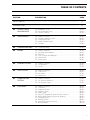
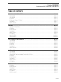
TABLE OF CONTENTS
SECTION
SUB-SECTION
PAGE
SAFETY NOTICE ..................................................................................................................................
II
INTRODUCTION ...................................................................................................................................
III
01
SERVICE TOOLS
AND PRODUCTS
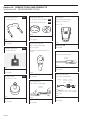
01 – Mandatory Tools....................................................................... 01-01-1
02 – Recommended Tools ............................................................... 01-02-1
03 – Service Products ...................................................................... 01-03-1
02
MAINTENANCE
00 – Table of contents......................................................................
01 – Periodic Inspection Chart .........................................................
02 – Flushing and Care.....................................................................
03 – Water-Flooded Engine..............................................................
04 – Storage .....................................................................................
03
TROUBLESHOOTING
00 – Troubleshooting........................................................................ 03-00-1
04
ENGINE
00 – Table of contents......................................................................
01 – Removal and Installation ..........................................................
02 –Top End .....................................................................................
03 – PTO Flywheel and Magneto.....................................................
04 – Bottom End ..............................................................................
05 – Rotary Valve .............................................................................
05
COOLING SYSTEM
00 – Table of contents...................................................................... 05-00-1
01 – Components............................................................................. 05-01-1
02 – Circuit ....................................................................................... 05-02-1
06
FUEL SYSTEM
00 – Table of contents......................................................................
01 – Fuel Circuit ...............................................................................
02 – Air Intake ..................................................................................
03 –Carburetors................................................................................
07
LUBRIFICATION
SYSTEM
00 – Table of contents...................................................................... 07-00-1
01 – Oil Injection Reservoir .............................................................. 07-01-1
02 – Oil Injection Pump .................................................................... 07-02-1
08
ELECTRICAL
00 – Table of contents......................................................................
01 – Overview ..................................................................................
02 – Magneto System......................................................................
03 – Ignition System ........................................................................
04 – Spark Plugs...............................................................................
05 –The DESS (Digitally Encoded Security System) ........................
06 –MPEM (Multi-Purpose Electronic Module)................................
07 –Charging System .......................................................................
08 –Starting System.........................................................................
09 –Instruments and Accessories....................................................
10 –Wiring Diagram..........................................................................
02-00-1
02-01-1
02-02-1
02-03-1
02-04-1
04-00-1
04-01-1
04-02-1
04-03-1
04-04-1
04-05-1
06-00-1
06-01-1
06-02-1
06-03-1
08-00-1
08-01-1
08-02-1
08-03-1
08-04-1
08-05-1
08-06-1
08-07-1
08-08-1
08-09-1
08-10-1
I
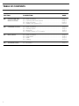
TABLE OF CONTENTS
II
SECTION
SUB-SECTION
PAGE
09
PROPULSION AND
DRIVE SYSTEMS
00 – Table of contents .....................................................................
01 – Propulsion and Drive Systems .................................................
02 – Reverse System.......................................................................
03 – Variable Trim System (VTS)......................................................
09-00-1
09-01-1
09-02-1
09-03-1
10
STEERING SYSTEM
00 – Table of contents .....................................................................
01 – Steering System ......................................................................
02 – Alignment.................................................................................
03 – Throttle / Shifter / VTS Controller .............................................
10-00-1
10-01-1
10-02-1
10-03-1
11
HULL / DECK
00 – Table of contents .....................................................................
01 – Components ............................................................................
02 – Repair.......................................................................................
03 – Painting ....................................................................................
11-00-1
11-01-1
11-02-1
11-03-1
12
TECHNICAL DATA
01 – All Models ................................................................................ 12-01-1
SAFETY NOTICE
SAFETY NOTINCE
This manual was primarily published to be used by jet boat technicians trained by the manufacturer who
are already familiar with all service and maintenance procedures relating to Bombardier made Sea-Doo
jet boat.
Please note that the instructions will apply only if proper hand tools and special service tools are used.
It is understood that this manual may be translated into local language upon certain conditions and furthermore agreed that in the event of any discrepancy among the two versions, the English version shall
prevail.
The content depicts parts and / or procedures applicable to the particular product at its time of manufacture. It does not include dealer modifications, whether authorized or not by Bombardier, after manufacturing the product.
The use of Bombardier parts is most strongly recommended when considering replacement of any component. Dealer and / or distributor assistance should be sought in case of doubt.
Torque wrench tightening specifications must be strictly adhered to. Locking devices (ex. : locking disk,
lock nut) must be installed or replaced with new ones, where specified. If the efficiency of a locking
device is impaired, it must be renewed.
This manual emphasizes particular information denoted by the wording and symbols ;
WARNING : Identifies an instruction which, if not followed, could cause serious
personal injury including possibility of death.
CAUTION : Denotes an instruction which, if not followed, could severely damage
watercraft components.
NOTE : Indicates supplementary information needed to fully complete an instruction.
;
'
Although the mere reading of such information does not eliminate the hazard, your understanding of the
information will promote its correct use. Always use common shop safety practice.
This information relates to the preparation and use of Bombardier jet boat and has been utilized safely
and effectively by Bombardier Inc. However, Bombardier Inc. disclaims liability for all damages and / or
injuries resulting from the improper use of the contents. We strongly recommend that any services be
carried out and / or verified by a highly skilled professional technician. It is understood that certain modifications may render use of the boat illegal under existing federal, provincial and state regulations.
III
1996 BOMBARDIER JET BOAT
SHOP MANUAL
INTRODUCTION
This Shop Manual covers the following BOMBARDIER made SEA-DOOr jet boats.
MODEL
MODEL NUMBER
SPORTSTER
5895
SPEEDSTER
5894
CHALLENGER
5896
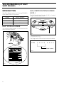
HULL IDENTIFICATION NUMBER
(H.I.N.)
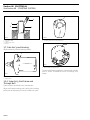
The Hull Identification Number (H.I.N.) is located
at right hand rear side of hull.
BOAT MODEL NUMBER
The jet boat model number can be found on RH
side of operator position.
3
2
4 5
3
2
6
7
1
min 8
0 1x /1000
Bombardier
4 5
6
1
7
1
min 8
0 1x /1000
Bombardier
Bombardier
F04L2SB
15
0
30
45
km/h
60
MPH
Bombardier
TYPICAL
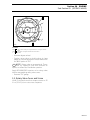
1. Hull Identification (H.I.N.)
OFF
ON
The 5 digits after ZZN are the boat serial number.
ZZN
1 2 3 4 5
X X X X
Serial number
F004A07A
WARNING
MADE IN CANADA BOMBARDIER INC.
1
F04L3QA
1. Model number
IV
XXXX
1996 BOMBARDIER JET BOAT
SHOP MANUAL
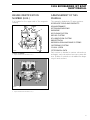
ENGINE IDENTIFICATION
NUMBER (E.I.N.)
ARRANGEMENT OF THIS
MANUAL
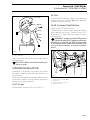
It is located on the upper side of the magneto
housing.
The manual is divided into 12 major sections :
01 SERVICE TOOLS AND PRODUCTS
02 MAINTENANCE
03 TROUBLESHOOTING
04 ENGINE
05 COOLING SYSTEM
06 FUEL SYSTEM
07 LUBRICATION SYSTEM
08 ELECTRICAL
09 PROPULSION AND DRIVE SYSTEMS
10 STEERING SYSTEM
11 HULL / DECK
12 TECHNICAL DATA
Each section is divided in various sub-sections,
and again, each sub-section has one or more division. A table of contents is included at the beginning of most sections.
1
F01D01A
TYPICAL-717 ENGINE
1. Engine Identification Number (E.I.N.)
F01D87A
1
787 ENGINE
1. Engine Identification Number (E.I.N.)
V
1996 BOMBARDIER JET BOAT
SHOP MANUAL
This Shop Manual uses technical terms which may be slightly
different from the ones in the Parts Catalog.
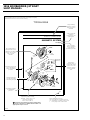
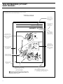
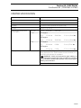
TYPICAL PAGE
Page heading
indicates section
and sub-section
detailed.
Section 08 ELECTRICAL
Sub-Section 01 (MAGNETO SYSTEM)
Sub-section title
indicates
beginning of the
sub-section.
MAGNETO SYSTEM
657 Engine
Italic sub-tiltle
above exploded
view indicate
pertaining models.
11
12
5 N•m
(44 lbf•in)
Drop represents a
liquid product to be
applied to a surface.
In this case Loctite
242 to screw
threads.
13
9 N•m
(80 lbf•in)
Loctite
242
8
6
4
7
SPORTSTER
Loctite Model Only
242
Dotted box
contains parts of
a particular model
(in this case, the
Sporster model )
or an exploded
view.
6 N•m
(53 lbf•in)
Loctite
242
Exploded view assits
you in identifying
parts and related
positions.
6 N•m
(53 lbf•in)
5
Loctite
242
3
14
Number indicates
special procedure
concerning this part.
Loctite
242
9
6 N•m
(53 lbf•in)
1
4
Loctite
648
10
15
145 N•m
(107 lbf•ft)
Anti-seize
lubricant
F01D4WS
2
9 N•m
(80 lbf•in)
Illustration number
for publishing
process.
08-01-1
Tightening torque nearby
fastener. In this case, nut
must be torqued to
145 N•m (107 lbf•ft).
CAUTION : Pay attention to torque specifications.
▼Some
of these are in lbf•in instead of lbf•ft. Use
appropriate torque wrench.
F04A04S
VI
Page numbering system :
08 : ELECTRICAL SYSTEM section
01 : MAGNETO SYSTEM sub-section
1 : First page of this sub-section
1996 BOMBARDIER JET BOAT
SHOP MANUAL
This Shop Manual uses technical terms which may be slightly
different from the ones in the Parts Catalog.
TYPICAL PAGE
Page heading
indicates section
and sub-section
detailed.
Section 08 ELECTRICAL
Sub-Section 01 (MAGNETO SYSTEM)
Sub-section title
indicates
beginning of the
sub-section.
MAGNETO SYSTEM
657 Engine
Italic sub-tiltle
above exploded
view indicate
pertaining models.
11
12
5 N•m
(44 lbf•in)
Drop represents a
liquid product to be
applied to a surface.
In this case Loctite
242 to screw
threads.
13
9 N•m
(80 lbf•in)
Loctite
242
8
6
4
7
SPORTSTER
Loctite Model Only
242
Dotted box
contains parts of
a particular model
(in this case, the
Sporster model )
or an exploded
view.
6 N•m
(53 lbf•in)
Loctite
242
Exploded view assits
you in identifying
parts and related
positions.
6 N•m
(53 lbf•in)
5
Loctite
242
3
14
Number indicates
special procedure
concerning this part.
Loctite
242
9
6 N•m
(53 lbf•in)
1
4
Loctite
648
10
15
145 N•m
(107 lbf•ft)
Anti-seize
lubricant
F01D4WS
2
9 N•m
(80 lbf•in)
Illustration number
for publishing
process.
08-01-1
Tightening torque nearby
fastener. In this case, nut
must be torqued to
145 N•m (107 lbf•ft).
CAUTION : Pay attention to torque specifications.
▼Some
of these are in lbf•in instead of lbf•ft. Use
appropriate torque wrench.
F04A04S
VI
Page numbering system :
08 : ELECTRICAL SYSTEM section
01 : MAGNETO SYSTEM sub-section
1 : First page of this sub-section
1996 BOMBARDIER JET BOAT
SHOP MANUAL
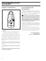
GENERAL INFORMATION
ILLUSTRATIONS AND
PROCEDURES
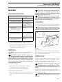
1
The illustrations show the typical construction of
the different assemblies and, in all cases, may not
reproduce the full detail or exact shape of the
parts shown, however, they represent parts
which have the same or a similar function.
CAUTION : These boats are designed
with parts dimensioned in both the metric
and the imperial systems. When replacing fasteners, make sure to use only those recommended by Bombardier. Mismatched or
incorrect fasteners could cause damage to the
boat or possible personal injury.
As many of the procedures in this manual are interrelated, we suggest, that before undertaking
any task, you read and thoroughly understand the
entire section or sub-section in which the procedure is contained.
A number of procedures throughout the book require the use of special tools. Before commencing any procedure, be sure that you have on hand
all the tools required, or approved equivalents.
4
2
5
F04L03B
1.
2.
3.
4.
5.
3
BOW (front)
STARBOARD (RH)
STERN (rear)
PORT (LH)
In marine insdustry, PORT, STARBOARD, BOW and STERN are
used to refer to LEFT, RIGHT, FRONT and REAR respectively.
They always refer to the operator’s position sitting in boat.
The information and component / system descriptions contained in this manual are correct at time
of publication. Bombardier Inc. however, maintains a policy of continuous improvement of its
products without imposing upon itself any obligation to install them on products previously manufactured.
Bombardier Inc. reserves the right at any time to
discontinue or change specifications, designs,
features, models or equipment without incurring
obligation.
This Shop Manual uses technical terms which
may be different from the ones of the Parts Catalogs.
When ordering parts always refer to the specific model Parts Catalogs.
VIII
Technical Publications
Bombardier Inc.
Valcourt (Quebec), Canada
Section 01 SERVICE TOOLS AND PRODUCTS
Sub-Section 01 (MANDATORY TOOLS)
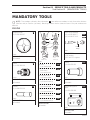
MANDATORY TOOLS
O
NOTE : The numbers outlined in black (example : 1 ) are reference numbers to tools from other divisions
(Sea-Doo and / or Sea-Doo Jet Boats). Matching numbers are the same tool even if the part numbers are
different.
ENGINE
Degree wheel
P / N 295 000 007
32
0
40
350 360 10
20
340
10 360 350 3
20
40
30
0
70
30
290
80
0
2
Piston
circlip
3
13
0
6
1
40
30
15
22
0
80 190 2
170 1
0
0
21
160
0
200 190 180 17
22
0
210
16
0
0
15
0
280
110 100 90
130
24
0
250
14
4
120
250
120
90 100 11
0
280 270 26
0
0
80
290
0
202
548
5
2
70
300
270
0
260
0
4
A01B1P4
0
A00B334
APPLICATION
All models.
MAG side
PTO side
F01D884
Puller
P / N 295 000 106
Piston circlip installer
A) P / N 295 000 077
B) P / N 290 877 016
40
32
60
23
7
7
1
0
31
24
8
30
33
60
0
50
8
50
31
33
0
1
5
1) Puller
200
APPLICATION
A) 587 engine.
B) 657 and 717 engines.
Pusher
P / N 290 876 605
229
P / N 290 876 298
2) Protective cap
(both ends)
554
P / N 290 876 557
3) Ring (both ends)
P / N 290 977 490
A00C1A4
APPLICATION
All models.
4) Ring halves (PTO)
A00C0Y4
556
P / N 290 977 475 (2)
5) Distance ring (MAG)
Pusher
P / N 290 876 500
555
12
557
P / N 290 876 569
6) Ring halves (MAG)
558
P / N 290 276 025 (2)
7) Screw M8 x 40
APPLICATION
All models.
Bombardier ignition
tester
P / N 295 000 008
236
559
P / N 290 840 681 (2)
A00B2J4
APPLICATION
All models.
8) Screw M8 x 70
560
IGNITION TESTER
40
50
60
30
P / N 290 841 201 (2)
Reset
70
20
80
Indicator
10
APPLICATION
All models.
90
0
100
Low
High
A00C1K4
APPLICATION
All models.
01-01-1
Section 01 SERVICE TOOLS AND PRODUCTS
Sub-Section 01 (MANDATORY TOOLS)
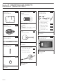
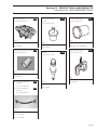
Rubber pad
P / N 295 000 101
547
PTO flywheel remover /
installer
P / N 295 000 001
553
Piston pin puller
P / N 295 000 092
1
566
2
3
F01J0T4
F01B0J4
Puller plate
P / N 290 876 080
549
APPLICATION
All models.
O
NOTE : This tool is also
used for the impeller.
Puller
P / N 290 876 488
562
Replacement parts :
1. Locating sleeve
P / N 290 877 181
2. Expansion sleeve
P / N 290 877 041
3. Extracting nut
P / N 290 877 155
772
771
770
F01B0V4
APPLICATION
All engines.
A00C1R4
Extension handle
P / N 295 000 125
MPEM programmer
P / N 295 000 127
550
F01B0I4
F01D164
Screw M8 x 35 (3)
P / N 290 841 591
551
APPLICATION
All models.
A) Alignment tool support
P / N 295 000 090
563
B) Alignment shaft
P / N 295 000 093
571
F00A094
Sleeve (3)
P / N 290 847 220
552
F01L2R4
F00A0A4
APPLICATION
All models.
01-01-2
APPLICATION
All models.
F01B254
APPLICATION
787 engine.
567
Section 01 SERVICE TOOLS AND PRODUCTS
Sub-Section 01 (MANDATORY TOOLS)
Ring gear blocking tool
P / N 295 000 134
568
F01B264
APPLICATION
787 engine.
Ring gear puller tool
P / N 420 976 235
569
F01B294
APPLICATION
787 engine.
01-01-3
Section 01 SERVICE TOOLS AND PRODUCTS
Sub-Section 01 (MANDATORY TOOLS)
COOLING / FUEL / OIL SYSTEMS
Hose pincher
P / N 295 000 076
2
Pliers
P / N 295 000 070
601
F01D174
APPLICATION
All models.
A01B2I4
APPLICATION
All models.
Gear holder
P / N 290 277 905
Pliers
P / N 295 000 054
606
235
F01B1T4
A00C164
APPLICATION
717 engine.
01-01-4
APPLICATION
All models.
NOTE : This tool is also used
for the propulsion system.
O
Section 01 SERVICE TOOLS AND PRODUCTS
Sub-Section 01 (MANDATORY TOOLS)
PROPULSION SYSTEM
Impeller remover /
installer
P / N 295 000 001
553
Bearing / seal installer
P / N 295 000 107
604
F01J0T4
APPLICATION
All models.
NOTE : This tool is also
used for the PTO flywheel.
O
Pliers
P / N 295 000 069
APPLICATION
All models.
602
Impeller shaft guide
P / N 295 000 002
F01D184
605
F01J1O4
APPLICATION
All models.
Impeller shaft holder
P / N 295 000 082
F01J4K4
APPLICATION
All models.
603
Pliers
P / N 295 000 054
606
F01B1T4
F01B0W4
APPLICATION
All models.
APPLICATION
All models.
NOTE : This tool is also used
for the fuel system.
O
01-01-5
Section 01 SERVICE TOOLS AND PRODUCTS
Sub-Section 02 (RECOMMENDED TOOLS)
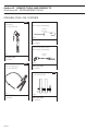
RECOMMENDED TOOLS
O
NOTE : The numbers outlined in black (example : 1 ) are reference numbers to tools from other divisions
(Sea-Doo and / or Sea-Doo Jet Boats). Matching numbers are the same tool even if the part numbers are
different.
ENGINE
Ring compressor
P / N 290 876 979
766
Stroboscopic timing light
P / N 295 000 078
225
Digital / induction type
tachometer
P / N 295 000 100
237
A01B1T4
APPLICATION
All engines.
Coil centering tool
P / N 290 876 922
F01B1G4
A01B2K4
209
APPLICATION
All models.
APPLICATION
All models.
Dial indicator
(TDC gauge)
P / N 295 000 143
230
Digital multimeter
P / N 529 022 000
242
VAC
VDC
MkΩ
_ +
0000
0
10
OFF
V
A01B1V4
V
APPLICATION
717 engine.
Cylinder aligning tool
P / N 290 876 904
30
20
300 mV
A00B2E4
Ω
APPLICATION
All models.
A
A
220
Distance gauge
A) P / N 290 876 827
B) P / N 290 876 828
VΩ
10 A
1000 V
750 V
561
760
COM
FUSED
F01B1O4
A00B084
APPLICATION
All models.
APPLICATION
All models.
F01B0H4
APPLICATION
A) 717 engine.
B) 787 engine.
01-02-1
Section 01 SERVICE TOOLS AND PRODUCTS
Sub-Section 02 (RECOMMENDED TOOLS)
Timing mark pointer
P / N 295 000 130
774
Ring halves and ring
P / N 290 876 330 (halves) 761
P / N 290 876 480 (ring)0 762
Spark tester
Not sold by Bombardier
Superex Canada Ltd
No. 15-785
F01B2D4
APPLICATION
787 engine.
F01B2O4
APPLICATION
717 engine.
Timing mark pointer
P / N 295 000 135
754
Engine lifting device
Not sold by Bombardier
Do it yourself
Refer to Shop Manual section
04-01
F01B1H4
APPLICATION
All models.
Terminal remover
Not sold by Bombardier
Snap-on
TT 600-4
F01B1J4
APPLICATION
All models.
F01H544
APPLICATION
787 engine.
Oil seal pusher
P / N 290 877 740
F01D0A4
759
APPLICATION
All models.
Feeler gauge 45°
Not sold by Bombardier
Slide hammer puller
Not sold by Bombardier
Snap-on : Handle CJ93-1
Hammer CJ125-6
Claws
CJ93-4
Snap-on
FB 300 A
O
NOTE : This tool is also
used to pull out impeller
shaft seal.
F01J0Z4
F01B2C4
F01B1K4
APPLICATION
787 engine.
01-02-2
APPLICATION
All models.
APPLICATION
All models.
Section 01 SERVICE TOOLS AND PRODUCTS
Sub-Section 02 (RECOMMENDED TOOLS)
Protective mat
P / N 295 000 129
890
Rotary valve shaft
pusher
P / N 290 876 609
757
F04L1V4
Exhaust outlet tool
P / N 295 000 132
831
F01B2A4
F01B2B4
APPLICATION
All models.
APPLICATION
Sportster and Speedster.
APPLICATION
787 engine.
Safety lanyard switch tool 775
P / N 295 000 121
Handle
P / N 290 877 650
758
Gear / bearing puller
P / N 290 877 665
765
F01B244
APPLICATION
All models.
A) Four-pin magneto
harness
P / N 295 000 131
B) Six-pin magneto
harness
P / N 295 000 136
F04B034
763
A00C3V4
APPLICATION
787 engine.
APPLICATION
787 engine.
755
F01B284
APPLICATION
A) 717 engine.
B) 787 engine.
01-02-3
Section 01 SERVICE TOOLS AND PRODUCTS
Sub-Section 02 (RECOMMENDED TOOLS)
COOLING / FUEL / OIL SYSTEMS
Pump gauge tester
(carburetor)
P / N 295 000 114
826
Screwdriver
Not sold by Bombardier
Snap-on
SDD-143
30
40
2
15
1
25
3
10
35
50
20
5
60
4
F01B1P4
APPLICATION
All models.
Lighted adjustable mirror
Not sold by Bombardier
Snap-on
50101
F01B0X4
APPLICATION
All models.
Pump gauge tester
(fuel / oil reservoirs)
P / N 295 000 085
F01B1I4
827
APPLICATION
All models.
Hose pincher
P / N 529 030 400
F01B0Y4
APPLICATION
All models.
01-02-4
F01B234
APPLICATION
All engines.
773
Section 01 SERVICE TOOLS AND PRODUCTS
Sub-Section 02 (RECOMMENDED TOOLS)
PROPULSION SYSTEM
Fitting
P / N 295 000 086
828
Machinist’s square
Not sold by Bombardier
Snap-on
PMF 122
Bearing remover
Not sold by Bombardier
Do it yourself
Refer to Shop Manual section
09-01
F01J114
F01B0Z4
APPLICATION
All models.
Slide hammer puller
Not sold by Bombardier
Snap-on : Handle
CJ93-1
Hammer CJ125-6
Claws
CJ93-4
O
NOTE : This tool is also
used to remove rotary valve
shaft bearing.
F02B064
APPLICATION
Models equipped with reverse.
Fitting remover
Not sold by Bombardier
Do it yourself
Refer to Shop Manual section
09-01
APPLICATION
All models.
Flexible spout (oil)
P / N 414 8373 00
834
APPLICATION
All models.
Deep socket
14 mm
(9/16 in)
F01J0Z4
APPLICATION
All models.
Hacksaw
Not sold by Bombardier
F01J2RA
APPLICATION
All models.
Snap-on
HS3
F01B1M4
APPLICATION
All models.
01-02-5
Section 01
SERVICE TOOLS AND PRODUCTS
Sub-Section 03 (SERVICE PRODUCTS)
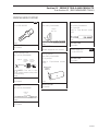
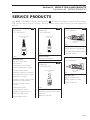
SERVICE PRODUCTS
O
NOTE : The numbers outlined in black (example : 1 ) are reference numbers to tools from other divisions
(Sea-Doo and / or Sea-Doo Jet Boats). Matching numbers are the same tool even if the part numbers are
different.
Medium strength
threadlocker
P / N 293 800 015
154
High strength
threadlocker
P / N 293 800 005
Loctite 242 (blue)
(10 mL)
155
Paste gasket
P / N 293 800 007
152
Loctite 271 (red)
(10 mL)
Loctite 515
(50 mL)
A00B2T4
APPLICATION
Cylinder sleeve / O-ring groove.
Crankcase halves mating surface.
Crankcase screws.
LOCTITE®
271
Adhesive Sealant
LOCTITE®
REMOVABLE
THREADLOCKER 242
A00B2U4
A00B324
APPLICATION
Cylinder head screws
(All engines).
Tuned pipe nut and screws.
Engine rubber mount screws.
Armature plate screws.
Magneto flywheel / crankshaft.
Carburetor mount nuts / screws.
Magneto coil screws.
Impeller housing cover screws
(except for plastic pumps).
Venturi / impeller housing
screws.
Intake grate screws.
Engine support screws.
Impeller housing / hull nuts.
Steering nozzle screws.
Reverse gate screws.
APPLICATION
Impeller shaft thread.
High temperature
threadlocker
P / N 290 899 788
Paste gasket
P / N 293 800 038
376
359
518
Loctite 518
(50 mL)
Loctite 648 (green)
(5 g)
F01B124
APPLICATION
Impeller housing cover.
Venturi / impeller housing.
Impeller shaft seal.
A00B3D4
APPLICATION
Crankcase / plug at end of rotary
valve shaft.
Magneto / ring gear.
01-03-1
Section 01 SERVICE TOOLS AND PRODUCTS
Sub-Section 03 (SERVICE PRODUCTS)
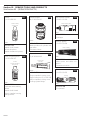
Solvent
P / N 293 800 019
157
Gasket stripper
N / P 295 500 110
935
Heat resistant sealant
P / N 413 709 200
Loctite Safety
Solvent 755
374
Dow Corning 736
DOW CORNING ®
RTV Sealant
n
Seala
736
tant
Resis
t
Heat
BOM
BARDIER
DÉ
CA
PANT
É
HÉIT
À JOINT D'ÉTANC
A00B3U4
295 000 110
500 ml
AV
NT
EXTR ERTISSEME ABLE
ÊMEMENT INFLAMM
VAPEUR NOCIVE
POISON
APPLICATION
Tuned pipe.
F01B1W4
A00B3M4
APPLICATION
Impeller shaft threads.
Drive shaft splines.
Impeller threads and splines.
Primer for paste gasket
P / N 293 600 013
158
APPLICATION
Mating surfaces of cylinders and
crankcase.
Crankcase halves.
Pipe sealant
P / N 293 800 018
A00B2W4
A00B3N4
APPLICATION
Crankcase halves mating
surface.
Impeller shaft thread.
Venturi / impeller housing
mating surface.
01-03-2
350
Dow Corning
358
Loctite 592
(50 mL)
Loctite
Locquic Primer N
170 g (6 oz)
Dielectric grease
P / N 293 550 004
APPLICATION
Plug on impeller housing cover.
Plastic fitting tool (P / N 295 000
086) on impeller housing cover.
Cooling system fittings.
F01B164
APPLICATION
Battery posts and cable connectors.
Thermosensor switch.
Grease
P / N 293 550 005
(400 g)
A00B2L4
APPLICATION
PTO flywheel.
924
Section 01
Synthetic grease
P / N 293 550 010
912
SERVICE TOOLS AND PRODUCTS
Sub-Section 03 (SERVICE PRODUCTS)
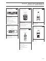
Anti-seize lubricant
P / N 293 800 023
362
Sea-Doo fuel stabilizer
P / N 413 408 600
375
Loctite anti-seize
lubricant
12 oz (454 g)
SYNTHETIC GREASE
Sea-Doo
(400 g)
F01B154
AU
NOUVE
APPLICATION
Cylinder and cylinder head
screws.
Carburetor linkage.
®
®
STABILISANT
D'ESSENCE
Impeller shaft seal lips.
Drive shaft / impeller splines.
PTO flywheel
Lubricant
Not sold by Bombardier
000
G.E. Versilube
G341M
F01B174
A00B3V4
APPLICATION
Crankshaft thread / PTO flywheel.
Crankshaft bearing seat.
Spark plug threads.
Ignition housing cover screws.
Penetrating lubricant
P / N 293 600 016
APPLICATION
Fuel system.
Bombardier-Rotax
915
injection oil
P / N 413 802 900 12 x 1 L
913
Bombardier
Lube
or
Esso Beacon 325
®
®
BOMBARDIER
®
Two-stroke
Injection Oil
A00B1T4
APPLICATION
Sliding surface of starter armature shaft splines.
!
AU
é!
ers
UVE inv
NOise même
vér
Pul
BOMBARDIER
1 U.S. quart
LUBE
REMP
LACE SEA-DOO LUBE
LUBRIF
F
IANT ANTICORROSI
Excellent en milieu salin
ou humide
340 g
F01B184
DANGER
INFLAMMABLE
CE CON
TENANT PEUT EXPLOSER
S'IL EST CHAUFFÉ.
L'INH
DUIT
ALATION
DIRECTE DE CE PRO
PEUT ÊTRE NOCIVE.
BOMBARDIER INC.
Sea-Doo
Valcourt, / Ski-Doo Division2LO
Québec, Canada J0E
APPLICATION
All models.
F01B0S4
APPLICATION
Throttle cable.
Wear ring (when new).
Corroded parts.
Water flooded engine.
Storage.
01-03-3
Section 01 SERVICE TOOLS AND PRODUCTS
Sub-Section 03 (SERVICE PRODUCTS)
Bombardier-Rotax
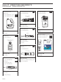
injection oil
P / N 413 803 000 3 x 4 L 916
P / N 413 803 200 205 L 962
732 Multi-purpose sealant 917
P / N 293 800 006
Adhesive activator
P / N 293 530 036
931
Dow Corning
(Clear)
ACTIVEUR D'ADHÉSIF
250 mL
POUR L'APPLICATION DE MOULURE
PRESSION
ET VINYLES SENSIBLES À LA
LORSQU'UNE MEILLEURE .
ADHÉRENCE EST NÉCESSAIRE
F01B1C4
®
BOMBARDIER
®
Two-stroke
4 U.S. quart
DANGER
APPLICATION
Ride shoe screws.
®
AVEC LA PEAU
-ÉVITER TOUT CONTACT PROLONGÉ
CAS DE CONTACT.
LAVER À L'EAU FROIDE EN
BIEN AÉRÉ.
-UTILISER DANS UN ENDROITFERMÉ.
-TENIR LE CONTENANT BIEN
DES ENFANTS.
-GARDEZ HORS DE LA PORTÉE
.
-CONTIENT DU TRICHLORETYLÈNE DE CE PRODUIT
-AVERTISSEMENT ! L'INHALATION
EST NOCIF.
N/P 293 530 036
FABRIQUÉ AU
Injection Oil
F01B1Z4
Sealant adhesive
P / N 293 800 033
F01B2H4
APPLICATION
All models.
934
APPLICATION
Decals.
Jet pump oil
P / N 293 600 011
ADCHEM
(Clear)
914
ADS E AL
SCELLANT ADHÉSIF PREMIÈRE QUALITÉ
PREMIUM SEALANT ADHESIVE
Sea-Doo Cleaner
P / N 293 110 001 400 g
P / N 293 110 002 4 L
000
946
947
F01B1S4
APPLICATION
Ride shoe screws.
Sponson.
Sea-Doo jet pump
synthetic oil
BOMBARDIER
CLEANER
400 g
General purpose instant
adhesive
P / N 293 800 021
®
HUILE SYNTHÉTIQUE À TURBINE
DANGER
DANGER
293 110 002
Loctite 495
F01B0P4
mvdiwpe ejfwf
fwfksmcs
LOCTITE
SUPER BOUNDER
bfh nhhfk
bfh nhhfk
kgeruer rijggla jwjetw rjjwetwm
wjtt
mvdiwpe ejfwf fwfksmcs
kgeruer
rijggla jwjetw
rjjwetwm wjtt
mvdiwpe ejfwf fwfksmcs
kgeruer rijggla jwjetw rjjwetwm
wjtt mvdiwpe ejfwf fwfksmcs
F01B2J4
APPLICATION
All models.
A00B2V4
A) Silicone «Ultra Black»
P / N 293 800 030
B) Silicone
«Ultra Black HB»
P / N 293 800 028
(300 mL)
F01B1A4
APPLICATION
Ride shoe.
Jet pump fittings.
01-03-4
901
902
BOMBARDIER
BOMBARDIER
373
APPLICATION
Rubber to metal bonding and
most hard plastic.
APPLICATION
All models.
EXTREMELY FLAMMABLE.
HARMFUL OR FATAL IF SWALLOWED.
VAPOUR HARMFUL.
4L
Section 01
Gelcoat spray paint
Super white
P / N 293 500 076
933
Sea-Doo
paint
VERTICAL
FANSPRAY
PATTERN
ROTATE
VALVE
NOZZLE 1/4
TURN TO
CHANGE
SPRAY
PATTERN
HORIZONTAL
FANSPRAY
PATTERN
Danvern Fanspray®
- A Sprayon Exclusive Feature
PEIN
TURE
POUR
GELCOAT
DA
NG
ER
SERVICE TOOLS AND PRODUCTS
Sub-Section 03 (SERVICE PRODUCTS)
Gun Kote
Not sold by Bombardier
000
Loctite sealant
P / N 413 7103 00
961
Kal-Gard
Coating & Mfg. Corp.
F000 000 000
F000 000 000
APPLICATION
Magneto and armature plate.
APPLICATION
Exhaust system 787 engine.
T
PAIN
R
DANGE
Gelcoat (liquid)
1 liter super white
P / N 293 500 075
943
F01B1Q4
APPLICATION
All models.
Spray paint for metallic parts only
A) White
926
P / N 293 500 029
B) Purple
930
P / N 293 500 020
Sea-Doo
paint
F000 000 000
APPLICATION
All models.
Epoxy glue
Not sold by Bombardier
3M-05900
F000 000 000
APPLICATION
All models.
Gelcoat repair kit
P / N 295 500 216
F01B0Q4
APPLICATION
A) Engine assembly.
B) Tuned pipe and muffler.
945
F000 000 000
APPLICATION
All models.
01-03-5
Section 02 MAINTENANCE
Sub-Section 00 (TABLE OF CONTENTS)
TABLE OF CONTENTS
PERIODIC INSPECTION CHART............................................................................................................. 02-01-1
FLUSHING AND CARE ........................................................................................................................... 02-02-1
FLUSHING........................................................................................................................................... 02-02-1
PROCEDURE ....................................................................................................................................... 02-02-1
CARE ................................................................................................................................................... 02-02-3
WATER-FLOODED ENGINE.................................................................................................................... 02-03-1
STORAGE................................................................................................................................................ 02-04-1
02-00-1
Section 02 MAINTENANCE
Sub-Section 01 (PERIODIC INSPECTION CHART)
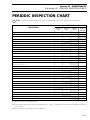
PERIODIC INSPECTION CHART
'
1
NOTE : Servicing period is given in hours. Shaded area shows the maintenance frequency.
FREQUENCY
DESCRIPTION
Every 10
hours
Lubrification / corrosion protection of metallic components
DESS operation / DESS post and safety lanyard cap terminal condition
Engine ignition timing
Spark plug replacement
Throttle / choke cables, inspection / lubrification
Flame arrester inspection
Carburetor adjustment including choke / throttle cable adjustment and linkage
Oil injection pump adjustment
Fuel filter and oil filter inspection
Fuel filter and oil filter replacement
Engine head screws, retorque
Steering system
Throttle / shifter VTS controller inspection / adjustment
Reverse system / reverse cable adjustment
Fastener tightening (flame arrester(s), carburator(s), engine(s),
exhaust system(s), etc.)
Muffler(s), battery and reservoir fastening devices
Fuel / oil lines, inspection, fuel system pressurization
Inspect / clean engine drain hose(s)
Bilge pump / deck drain hole inspection
Battery condition
Battery and starter cables
Monitoring beeper / electrical connections
Impeller shaft reservoir oil level / condition
Impeller condition and impeller / wear ring and clearance
➀
Drive shaft boot / spline condition (both ends)
PTO flywheel lubrification
Water intake grate condition
Hull / ride shoe condition
Cooling system flushing ➂
Zinc anodes
Bilge air blower inspection
Every 25
hours
Every 50
hours
Every 100
hours or
seasonally
➀
➀
Replace
➁
➁
➁
➀ Every 10 hours in salt water use.
➁ These items have to be initially checked after 25 hours. Thereafter, servicing to be made as specified
in this chart.
➂ Daily flushing in salt water or foul water use.
02-01-1
Section 02 MAINTENANCE
Sub-Section 02 (FLUSHING AND CARE)
FLUSHING AND CARE
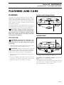
FLUSHING
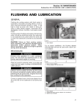
Flushing the cooling system with fresh water is
essential to neutralize corroding effects of salt or
other chemical products present in water. It will
help to clear sand, salt, shells or other particles in
water jackets (engine, exhaust manifold, tuned
pipe) and / or hoses.
Flushing should be performed when the boat is
not expected to be used further the same day or
when the boat is stored for any extended time.
CAUTION : Failure to flush cooling system, when necessary, will severely damage engine and / or exhaust system. Never
flush a hot engine. Make sure engine operates
during entire procedure.
-
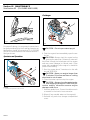
2
Sportster and Challenger Models
F04L2SA
1
1. Flushing connector
Speedster Model
PROCEDURE
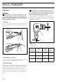
1
; well ventilated area. Do not touch any
electrical parts or jet pump area when engine
WARNING : Perform this operation in a
is running.
1. Clean jet pump by spraying water in its inlet and
outlet and then spray a soapy solution.
WARNING : Always remove safety lanyard
cap from DESS post to prevent accidental
engine starting before cleaning the jet pump area.
Engine must not be running for this operation.
2. Open rear storage compartment and remove
storage tray.
3. Connect a garden hose directly to the flushing
connector. To prevent water leak, ensure the
rubber washer is in the boat’s connector.
;
F04L2XA
1. Flushing connector for port engine (LH side)
2. Flushing connector for starboard engine (RH side)
' operation on each engine.
NOTE : On Speedster model, perform the
The engine can also be flushed from the flushing
connector that is located on the edge of the engine compartment. See illustration.
02-02-1
Section 02 MAINTENANCE
Sub-Section 02 (FLUSHING AND CARE)
Challenger
1
1
F04E0JA
1. Flushing connector with its cap
F04E0IA
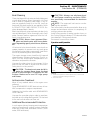
For proper flushing, it is necessary to prevent water going out directly by the flushing connector on
the transom. Install a hose pincher (P / N 529 030
400) on the hose between the transom and the Tfitting as shown.
Sportster and Speedster
1. Install a hose pincher in this section
-
4. Start the engine then immediately open the water tap.
CAUTION : Always start the engine before
opening the water tap. Otherwise, water will
back flow through the tuned pipe into the engine
and may cause damage to internal parts. Open
water tap immediately after engine is started to
prevent overheating.
5. Run the engine about 3 minutes at a fast idle
around 3500 RPM.
CAUTION : Never run engine longer than
5 minutes. Drive line seal has no cooling
when boat is out of water.
6. Close the water tap then stop the engine.
CAUTION : Always close the water tap before stopping the engine. Follow this procedure exactly otherwise severe engine
damage could occur.
7. Remove garden hose. Ensure the rubber washer remains in the boat’s hose connector.
8. Wipe off any residual water on the engine(s).
9. Reinstall tray and close storage compartment
cover.
1
F04E0HA
TYPICAL
1. Install a hose pincher in this section
02-02-2
CAUTION : Do not open water tap yet.
-
Section 02 MAINTENANCE
Sub-Section 02 (FLUSHING AND CARE)
CARE
1. Check joints for leaks to avoid water accumulation in the bilge.
2. Do not modify hose or socket size as coolant
flow could be altered.
3. When engine is running, water must flow from
bleed outlet(s) indicating that water circulates.
4. For hose clamp installation, use special pliers (P
/ N 295 000 070).
5. When installing hoses onto fittings or when
troubleshooting for water intake in the bilge area, confirm that all hoses are properly secured
to the fittings.
6. Check monitoring beeper operation by jumping
terminal of thermosensor wire to ground.
Beeper must operate.
At every verification of monitoring beeper always
apply dielectric grease on thermosensor connector.
Verify wire terminal on connector for tightness. If
too loose, squeeze terminal slightly at installation.
CAUTION : When investigating for no water flow in the cooling system, check all
elbows and straight fittings as well as all hoses
for blockage.
-
02-02-3
Section 02 MAINTENANCE
Sub-Section 03 (WATER-FLOODED ENGINE)
WATER-FLOODED ENGINE
General
If engine is water-flooded, it must be serviced
within a few hours after the event. Otherwise engine will have to be overhauled.
CAUTION : A water-flooded engine must
be properly lubricated, operated then lubricated again, otherwise parts will be seriously damaged.
-
Procedure
Check fuel and oil reservoirs for water contamination. If necessary, siphon and refill with fresh fluids.
Turn fuel valve(s) to OFF position then drain fuel
filter bowl(s). Refer to FUEL SYSTEM, 06-01.
Drain bilge if water is present.
Remove spark plug cables and connect them on
the grounding device.
WARNING : Never crank engine with
spark plugs removed unless spark plug
cables are connected to the grounding device.
;
3
3
-
CAUTION : Be careful when cranking engine(s), water will spray out from spark
plug holes.
Spray BOMBARDIER LUBE lubricant (P / N 293
600 006) into spark plug holes.
Crank engine(s) again.
Reinstall spark plugs and spark plug cables then
safety lanyard cap on DESS post.
Turn fuel valve(s) to ON position.
Start engine(s)þ; It may be necessary to use the
choke. If engine(s) do not start, repeat previous
steps as necessary.
CAUTION : To avoid starting motor overheating, the cranking period should not
exceed 5-10 seconds and a rest period of 30
seconds should be observed between cranking
cycles.
NOTE : If engine(s) do not start after several
aTtempts, check ignition system for spark
occurence. Refer to ELECTRICAL SYSTEM, 08.
Check crankshaft if needed, it can become misaligned or deflected. Refer to ENGINE, 04-04.
After engine has started, spray BOMBARDIER
LUBE lubricant through air intake silencer while
engine is running.
'
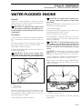
2
2
1
3
1
F01H27B
TYPICAL
1. Magneto housing
2. Grounding device
3. Spark plug cables
Remove spark plugs and dry them with a clean
cloth. A contact cleaner spray can be used. It may
be preferable to replace spark plugs. Do NOT install spark plugs on engine.
Crank engine(s) to drain crankcase.
F01F25A
1. Air intake silencer cover
2. Pull plug
3. Spray BOMBARDIER LUBE here
Run engine until it reaches its normal operating
temperature.
02-03-1
Section 02 MAINTENANCE
Sub-Section 03 (WATER-FLOODED ENGINE)
-
CAUTION : Water must be supplied to
cool engine(s) through the boat’s flushing
connector(s).
02-03-2
Section 02 MAINTENANCE
Sub-Section 04 (STORAGE)
STORAGE
4
Engine Draining
Fuel System
Check engine drain hose running from engine
manifold fitting to outlet socket. Make sure there
is no sand or other particles in it and that it is not
obstructed so that water can leave the engine.
Clean hose and outlet socket as necessary.
CAUTION : Water in engine drain hose
must be free to flow out, otherwise water
could be trapped in engine. Should water
freeze in engine, severe damage will occur.
Check engine drain hose for obstructions.
Sea-Doo Fuel Stabilizer (P / N 413 408 600) can be
added in fuel tank to prevent fuel deterioration
and carburetor gumming. Follow manufacturer’s
instructions for proper use.
CAUTION : Fuel stabilizer should be added prior engine lubrication to ensure carburetor protection against varnish deposit.
WARNING : Fuel is flammable and explosive under certain conditions. Always
work in a well ventilated area. Do not smoke or
allow open flames or sparks in the vicinity. Always wipe off any fuel spillage from the boat.
-
Sportster and Speedster
;
Cooling System Flushing and Engine
Internal Lubrication
Cooling system has to be flushed with fresh water to prevent salt, sand or dirt accumulation
which will clog water passages. This will be
achieved with a garden hose.
Refer to flushing, section 02-02 and follow the
procedure.
Internal Lubrication
Engine must be lubricated to prevent corrosion on
internal parts. This will be achieved by spraying
BOMBARDIER LUBE lubricant (P / N 293 600 006)
through air intake silencer.
1. After the flushing procedure and the engine has
been running as prescribed, spray BOMBARDIER LUBE lubricant through air intake silencer
cover keeping engine at fast idle.
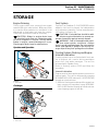
1
F04E0HC
TYPICAL
1. Drain tube
Challenger
1
F04E0IC
TYPICAL
1. Drain tube
02-04-1
Section 02 MAINTENANCE
Sub-Section 04 (STORAGE)
6. Remove both spark plugs and spray BOMBARDIER LUBE lubricant into each cylinder.
7. Crank the engine a few turns to distribute the
oil onto cylinder wall.
8. Apply antiseize lubricant (P / N 293 550 001) on
spark plug threads then reinstall them.
9. Reinstall plug on air intake silencer cover.
CAUTION : Do not run the engine during
the storage period.
2
1
3
-
Propulsion System
F01F25A
1. Air intake silencer cover
2. Pull plug
3. Spray BOMBARDIER LUBE here
Lubrication of engine should be done at least for
1 minute. After approximately half a minute, close
fuel valve to run engine out of fuel while lubricating.
CAUTION : When engine begins to run irreguIarly because of fuel starvation, immediately stop water flow before engine dies,
otherwise severe engine damage could occur.
2. Close the water tap then stop the engine.
3. Remove garden hose from boat’s connector.
Ensure rubber washer remains in the connector.
4. Wipe up any residual water from the engine.
5. Remove spark plug cables and connect them
on the grounding device.
-
Lubricant in impeller shaft reservoir should be
drained. Reservoir should be cleaned and refilled
with 90 mL (3 U.S. oz) of BOMBARDIER synthetic
75W 90 GL5 polyolester oil (P / N 293 600 011).
Refer to PROPULSION AND DRIVE SYSTEMS
09-01.
CAUTION : Use only BOMBARDIER jet
pump oil or equivalent synthetic gear oil,
otherwise component service life could be reduced. Do not mix oil brands or types.
Lubricate PTO flywheel at grease fitting with synthetic grease (P / N 293 550 010).
CAUTION : Do not lubricate excessively.
Immediately stop when a slight movement is noticed on rubber boot.
-
3
2
F01I0BA
1
1. Grease PTO flywheel
F01H27B
TYPICAL
1. Magneto housing cover
2. Grounding device
3. Spark plug cables
02-04-2
1
CAUTION : Never leave any clothing, tool
or other objects in engine compartment.
Battery
For battery removal, cleaning and storage, refer to
ELECTRICAL 08-03
Section 02 MAINTENANCE
Sub-Section 04 (STORAGE)
Boat Cleaning
Clean the bilge with hot water and mild detergent
or with bilge cleaner. Rinse thoroughly. Lift front
end of boat to completely drain bilge. If any repairs are needed to body or to the hull, touch up
paint and Gelcote® repair kit are available. Refer
to SERVICE TOOLS AND PRODUCTS 01-02. Replace damaged labels / decals.
Wash the body with soap and water solution (only
use mild detergent). Rinse thoroughly with fresh
water. Remove marine organisms from the hull.
Apply a nonabrasive wax.
CAUTION : Never clean apparent fiberglass and plastic parts with strong detergent, degreasing agent, paint thinner, acetone,
etc.
If the boat is to be stored outside, cover it with an
opaque tarpaulin to prevent sun rays and grime
from affecting the plastic components, boat finish
as well as preventing dust accumulation.
The engine storage cover should be left opened
during storage. Remove storage tray. Place it on
deck. This will avoid engine compartment condensation and possible corrosion.
Unscrew the drain plugs for the storage, lift the
boat so that the bow is higher then the stern.
Safely block it in this position.
CAUTION : The boat must never be Ieft in
water for storage. Never leave the boat
stored in direct sunlight. UV radiation will dull
finishes. Make sure to turn OFF bilge pump
and blower.
-
-
-
CAUTION : Always use ethylene-glycol
anti-freeze containing corrosion inhibitors specifically recommended for aluminum
engines.
NOTE : The engine will not have to run during this operation.
Two hoses have to be disconnected to allow air to
escape and antifreeze solution to completely fill
cooling system water jackets.
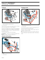
Install a hose pincher on water injection hose, on
the Cooling System Indicator (CSI) tube and outlet
hose between T-fitting and transom.
Disconnect hoses where shown.
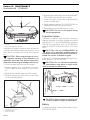
'
Sportster and Speedster
2
1
1
F04E0HB
TYPICAL
1. Install a hose pincher on water injection hose, CSI hose and
outlet hose between T-fitting and transom
2. Disconnect here
Anticorrosion Treatment
Wipe off any residual water in the engine compartment.
Spray BOMBARDIER LUBE lubricant over all metallic components in engine compartment.
Lubricate the throttle cable with BOMBARDIER
LUBE lubricant.
Unscrew the rear drain plug in order to avoid water build up in the bilge during rainfall. Tilt the boat
to the rear so that water can flow out.
Additional Recommended Protection
In cool regions (where freezing point temperature
may be encountered), cooling system should be
filled with water and antifreeze solution. (40%
water, 60% antifreeze).
02-04-3
Section 02 MAINTENANCE
Sub-Section 04 (STORAGE)
Challenger
Challenger Model
1
2
1
1
2
F04E0IB
TYPICAL
1. Install a hose pincher on water injection hose, CSI hose and
outlet hose between T-fitting and transom
2. Disconnect here
Raise all hoses above the highest point of tuned
pipe and temporarily tie them together.
Unscrew cap and insert a funnel into the flushing
fitting on the edge of the engine compartment.
Pour about 2 liters (1/2 gal) of antifreeze solution
through the funnel.
Tie up all hoses higher than tuned pipe.
NOTE : f hoses are not attached higher than
tuned pipe, coolant will drain out.
'
Sportster and Speedster
2
1
F04E0KA
TYPICAL
1. Hold hoses higher than tuned pipe
2. Flushing fitting
02-04-4
F04E0LA
TYPICAL
1. Hold hoses higher than tuned pipe
2. Flushing fitting
The following steps should be performed to provide the boat enhanced protection.
Remove muffler and drain out as much water as
possible. Reinstall muffler.
OR : Disconnect one hose from muffler and pour
some antifreeze liquid inside muffler. Reconnect
hose.
Section 03
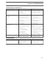
TROUBLESHOOTING
TROUBLESHOOTING
0
The following chart is provided to help in diagnosing the probable source of troubles. It is a guideline and
should not be assumed to have all causes for all problems.
ENGINE WILL NOT START
OTHER OBSERVATION
POSSIBLE CAUSE
REMEDY
Engine does not turn over
• Battery connections
• Safety lanyard cap worn or removed
• Turn to ON. Check, refer to section0805
• Replace / reinstall
• Start / stop button defective
• Burnt 5 A fuse (MPEM supply)
• Check, refer to section 08-05
• Check wiring then replace fuse
• 5 A fuse keeps on burning (MPEM sup- • Check wiring and MPEM refer to secply)
tion 08-05. Replace fuse
• Discharged battery
• Check / recharge
• Ignition switch not turned ON or defec- • Check / clean / tighten
tive
• Water / fuel hydrolock
• Check, refer to section 02-03
Engine slowly turns
• Starter or solenoid
• Seized engine
• Check, refer to section 08-07
• Check / repair as needed
• Seized jet pump
• Jammed pump
• Check, refer to section 09-01
• Check / clean out debris
• Discharged / weak battery
• Battery connections
• Check / charge / replace
• Check / tighten connections
• Restriction in jet pump
• Seizure in jet pump
• Check / clean pump
• Inspect, refer to section 09-01
• Seal carrier seizure
• Partial engine hydrolock
• Check, refer to section 09-01
• Check, refer to section 02-03
• Partial engine seizure
• Worn starter
• Check compression, refer to section
04-02
• Check, refer to section 08-07
• Wear ring improperly installed
• Check / replace, refer to section09-01
03-00-1
Section 03
TROUBLESHOOTING
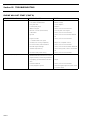
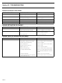
ENGINE WILL NOT START (CONT’D)
OTHER OBSERVATION
POSSIBLE CAUSE
REMEDY
Engine turns over
• Fuel tank empty
• Refill
• Fuel water-contaminated
• Dirty fuel filter
• Renew supply
• Clean / replace
• Fouled spark plugs
• Water in engine
• Replace
• Check, refer to section 02-03
• Misuse of choke (fuel flooded)
• Carburetion
• Use only with cold engine
• Check, refer to section 06-03
• Ignition
• Check, refer to section 08-03 and 0805
• Engine flooded
— Needle valve stuck open
• Choke(s) not closing completely
• Check, refer to section 06-03
• Excessive rotary valve clearance
• Internal engine damage
• Check, refer to section 04-05
• Check, refer to section 04-02 and04-04
• Sheared flywheel key
• Check timing mark, refer to section0803
• Incorrect rotary valve timing
• Grounded BLACK / RED / GREEN wire
(additional BLACK / RED wire on twin
engine models) connecting to MPEM
• Unproperly grounded MPEM BLACK
wire
• Defective MPEM
• Check, refer to section 04-05
• Repair
• Faulty magneto system
• Check wiring and ignition system, refer
to section 08-03
No spark at spark plugs
03-00-2
• Adjust for complete closure
• Repair
• Check, refer to section 08-05
Section 03
TROUBLESHOOTING
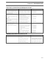
ENGINE MISFIRES, RUNS IRREGULARLY
OTHER OBSERVATION
POSSIBLE CAUSE
REMEDY
Weak spark
• Fouled, defective, worn spark plugs
• Check / verify heat range / gap /replace
• Faulty MPEM or start / stop switch
• Faulty ignition
• Check, refer to section 08-05
• Check, refer to section 08-03
• Sheared flywheel key
• Check timing mark, refer to section0803
• Fuel level low
• Stale or water fouled fuel
• Check / refill
• Check / siphon and refill
• Fuel filter dirty or restricted
• Carburetion dirty or out of adjustment
• Check / clean / replace
• Check / clean / adjust, refer to section
06-03
Lean fuel mixture
Dry spark plug (except when water
fouled)
• Leaking crankshaft seal(s), rotary valve • Check / test / replace, refer to engine
cover O-ring(s)
section 04-04 and 04-05
• Fuel valve restricted or partially opened • Check / replace / turn fully ON
• Loose carburetor
• Tighten carburetor(s)
Rich fuel mixture
Fouled spark plug
• Partially closed choke
• Flame arrester dirty or restricted
• Check / adjust choke cable
• Check / clean / replace
• Carburetor adjustment or setting
• Check / clean / adjust, refer to section
06-03
• Main jet loose
• Main jet O-ring damage
• Check, refer to section 06-03
• Check / replace, refer to section 06-03
• Rotary valve shaft seal leaking
• Oil pump adjustment
• Check / replace, refer to section 04-05
• Check / adjust, refer to section 07-02
• Boat transportation
• Worn needle(s) and seat(s)
• Turn fuel valve to OFF
• Check, refer to section 06-03
• Excessive rotary valve clearance
• Incorrect rotary valve timing
• Check, refer to section 04-05
• Check / adjust, refer to section 04-05
• Excessive rotary valve clearance
• Check, refer to section 04-05
OTHER OBSERVATION
POSSIBLE CAUSE
REMEDY
Monitoring beeper continuously sounds
• Restricted jet pump water intake
• Check / clean
Difficult to start
ENGINE OVERHEATS
• Cooling system restriction
• Check / flush, refer to section 02-02
• Grounded temperature sensor or sen- • Check / repair / replace
sor wire
03-00-3
Section 03
TROUBLESHOOTING
ENGINE CONTINUALLY BACKFIRES
OTHER OBSERVATION
POSSIBLE CAUSE
REMEDY
Weak spark
• Fouled, defective spark plugs
• Clean / replace
Ignition timing
• MPEM malfunction
• Incorrect setting
• Check, refer to section 08-05
• Check / reset, refer to section 08-03
Rotary valve
• Flywheel key sheared
• Timing incorrect
• Check / replace
• Check / reset, refer to section 04-05
Carburetor
Engine
• Carburetion too lean
• Intake leak / crankshaft seal failure
• Check / adjust, refer to section06-03
• Pressure check engine to 48 kPa(7 PSI)
ENGINE DETONATION OR PINGING
OTHER OBSERVATION
POSSIBLE CAUSE
REMEDY
Ignition
• Timing too far advanced
• Spark plug heat range too high
• Check / reset
• Check / change to correct range
Engine temperature
• Engine overheating
• Check, refer to section 02-03 and 0501 or to engine overheat
• Poor quality fuel
• Use good quality fuel
ENGINE LACKS ACCELERATION OR POWER
OTHER OBSERVATION
POSSIBLE CAUSE
REMEDY
• Weak spark
• Check / replace, refer to section08-03
• Carburetion, jetting too rich / lean
• Throttle does not open fully
• Check / adjust, refer to section06-03
• Check / readjust
• Low compression
• Exhaust system restriction
• Check / repair, refer to section 04-02
• Check / clean
• Water in gas or oil
• Debris in needle valve
• Check / siphon / replace
• Check / clean, refer to section 06-03
• Jet pump related problem
• Refer to ”POOR START,ACCELERATION OR PERFORMANCE OF BOAT”
below
• Check, refer to section 04-04
• Twisted crankshaft
• Cooling system water flow regulator
valve (challenger only)
03-00-4
• Check / adjust, refer to section05-01
Section 03
TROUBLESHOOTING
POOR START, ACCELERATION OR PERFORMANCE OF BOAT
OTHER OBSERVATION
POSSIBLE CAUSE
REMEDY
• Trailing edge of impeller is damaged
• Leading edge of impeller is damaged
• Check / Replace
• Check / Replace
Jet pump cavitation :
• Poor start / acceleration of boat
• Poor top performance of boat and / or
stator vanes erosion
Jet pump ventilation :
Engine RPM is high and boat is slow to
accelerate
OR engine does not react quickly when
pushing on throttle lever (assuming that
engine is correct)
OR engine does not keep a steady top
RPM (assuming that engine is correct)
Other problem with jet pump
(related to performance) :
Boat does not reach its top speed
• Pump improperly sealed to ride shoe; • Check / Reseal / Install a new neoprene
insufficient sealant on the ride shoe or
seal
missing neoprene seal
• Through-hull seal around drive shaft ; • Check / Replace
air comes from inside the boat
• Retaining screws of ride shoe; air
• Check / Reseal
comes from inside the boat.
• Retaining screws of intake grate; air
comes from inside the boat.
• Check / Reseal
• A wear ring with excessive clearance
• A damaged or worn pump housing
• Check / Replace
• Check / Replace
• A damaged impeller
• An impeller with the wrong pitch
(too low)
• Missing or damaged impeller boot
• Check / Replace
• Check / Replace
• Weeds or debris in intake grate
• Weeds or debris in intake grate
• Check / Clean
• Check / Clean
• Check / Install
ABNORMAL NOISE FROM PROPULSION SYSTEM
OTHER OBSERVATION
POSSIBLE CAUSE
REMEDY
• Weeds / debris caught in pump intake • Check / clean
or impeller
• Low oil level in pump housing
• Check / troubleshoot source of leak /
refill supply, refer to section 09-01
• Damaged or bent drive shaft
• Broken motor mounts
• Check / replace, refer to section 09-01
• Check / replace, refer to section 04-01
• Rusted / worn hull seal carrier
• Check / repair, refer to section 09-01
03-00-5
Section 04 ENGINE
Sub-Section 00 (TABLE OF CONTENTS)
TABLE OF CONTENTS
REMOVAL AND INSTALLATION............................................................................................................
717 ENGINE.........................................................................................................................................
787 ENGINE.........................................................................................................................................
GENERAL.............................................................................................................................................
REMOVAL FROM JET BOAT ...............................................................................................................
CLEANING ...........................................................................................................................................
INSTALLATION ....................................................................................................................................
04-01-1
04-01-1
04-01-2
04-01-3
04-01-3
04-01-7
04-01-7
TOP END ................................................................................................................................................. 04-02-1
ENGINE DESCRIPTION .......................................................................................................................
GENERAL.............................................................................................................................................
DISASSEMBLY ....................................................................................................................................
CLEANING ...........................................................................................................................................
INSPECTION ........................................................................................................................................
ASSEMBLY ..........................................................................................................................................
RAVE SYSTEM .....................................................................................................................................
SQUISH AREA .....................................................................................................................................
04-02-2
04-02-2
04-02-2
04-02-4
04-02-4
04-02-7
04-02-12
04-02-14
PTO FLYWHEEL AND MAGNETO.......................................................................................................... 04-03-1
717 ENGINE.........................................................................................................................................
787 ENGINE.........................................................................................................................................
GENERAL.............................................................................................................................................
REMOVAL............................................................................................................................................
CLEANING ...........................................................................................................................................
INSTALLATION ....................................................................................................................................
04-03-1
04-03-2
04-03-3
04-03-3
04-03-8
04-03-8
BOTTOM END ......................................................................................................................................... 04-04-1
717 ENGINE.........................................................................................................................................
787 ENGINE.........................................................................................................................................
CRANKSHAFT MISALIGNMENT AND DEFLECTION ..........................................................................
GENERAL.............................................................................................................................................
DISASSEMBLY ....................................................................................................................................
CLEANING ...........................................................................................................................................
INSPECTION ........................................................................................................................................
ASSEMBLY ..........................................................................................................................................
04-04-1
04-04-6
04-04-3
04-04-4
04-04-4
04-04-6
04-04-6
04-04-8
ROTARY VALVE ...................................................................................................................................... 04-05-1
GENERAL.............................................................................................................................................
DISASSEMBLY ....................................................................................................................................
CLEANING ...........................................................................................................................................
INSPECTION ........................................................................................................................................
ASSEMBLY ..........................................................................................................................................
ROTARY VALVE....................................................................................................................................
04-05-2
04-05-2
04-05-4
04-05-4
04-05-6
04-05-8
04-00-1
Sub-Section 01
Section 04 ENGINE
(REMOVAL AND INSTALLATION)
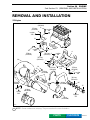
REMOVAL AND INSTALLATION
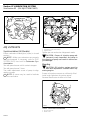
1
717 Engine
25 N•m
(18 lbf•ft)
9
25 N•m
(18 lbf•ft)
Loctite
242
Loctite
242
11
7
12
25 N•m
(18 lbf•ft)
Loctite
242
4
25 N•m 6
(18 lbf•ft)
8
25 N•m
(18 lbf•ft)
10
Loctite
242
1
2
3
12
25 N•m
(18 lbf•ft)
14
13
Loctite
242
35 N•m
(26 lbf•ft)
5
Loctite
242
4 N•m
(35 lbf•in)
30 N•m
(22 lbf•ft)
4 N•m
(35 lbf•in)
25 N•m
(18 lbf•ft)
16
15
14
Loctite
242
10 N•m
(88 lbf•in)
14
7 N•m
(62 lbf•in)
Sealant
732
F04D04S
'
NOTE : Some numbers are missing. They are used on the next illustration.
PARTS
FLAT RATE
04-01-1
Section 04 ENGINE
Sub-Section 01 (REMOVAL AND INSTALLATION)
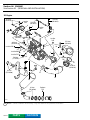
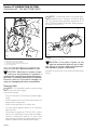
787 Engine
25 N•m
(18 lbf•ft)
Loctite
242
4
25 N•m
(18 lbf•ft)
25 N•m
(18 lbf•ft)
3
Loctite
242
2
25 N•m
(18 lbf•ft) Loctite
242
Loctite
242
40 N•m
(30 lbf•ft)
25 N•m
(18 lbf•ft)
6
Loctite 242
14
9
Loctite 648
7
13
44
3
Loctite 515
24 N•m
(17 lbf•ft)
8
Sealant
736
1
15
10 N•m
(88 lbf•ft)
2
4 N•m
(35 lbf•in)
11
10
4 N•m
(35 lbf•in)
Sealant
732
F04D05S
'
NOTE : Some numbers are missing. They are used on the previous illustration.
04-01-2
PARTS
FLAT RATE
Sub-Section 01
Section 04 ENGINE
(REMOVAL AND INSTALLATION)
GENERAL
It is not necessary to remove engine from jet boat
for TOP END nor PTO FLYWHEEL AND MAGNETO servicing. However engine removal is necessary to repair BOTTOM END AND ROTARY
VALVE.
Speedster Model
Although that basically the same engines are
used for port and starboard, there are differences
in hardware such as, choke / throttle cable
lengths, fuel / oil lines, electrical wiring etc. Properly identify engines prior to removal.
REMOVAL FROM JET BOAT
' ment, it is suggested to remove rear storage
compartment cover from boat.
NOTE : To ease working in engine compart-
In order to remove engine from jet boat proceed
as follows.
CAUTION : Whenever removing engine
from jet boat, engine / jet pump alignment must be performed.
-
F01D7NA
1
787 ENGINE SHOWN
1. Connector
Disconnect cooling system hoses from engine
head.
Disconnect bleed hose at T-fitting close to engine.
Disconnect muffler from tuned pipe.
To withdraw jet pump unit ass’y, refer to PROPULSION AND DRIVE SYSTEMS, 09-01 then refer to Jet Pump Removal.
Fuel System
Turn fuel valve to OFF position.
Disconnect fuel supply line from carburetor.
Disconnect fuel return line from carburetor.
Disconnect throttle and choke cables from carburetor.
Electrical Connections
Oil System
;
To prevent excessive oil spillage, use a hose
pincher (P / N 295 000 076).
Jet Pump Removal
WARNING : Always disconnect starter or
battery cables exactly in the specified order, BLACK negative cable first. Electrolyte or
fuel vapors can be present in the engine compartment and a spark might ignite them and
possibly cause personal injuries. It is recommended to disconnect electrical connections
prior to disconnecting fuel lines.
First, remove BLACK negative cable from battery(ies), then RED positive cable.
Disconnect thermosensor wire(s) and spark plug
cables.
Disconnect magneto wires at connector of engine.
295 000 076
A01B2JA
TYPICAL
04-01-3
Section 04 ENGINE
Sub-Section 01 (REMOVAL AND INSTALLATION)
Engine Support Mounts
Remove engine support mount screws.
NOTE : Be careful when removing engine
support mount screws, shims could have
been installed between engine support and rubber mounts. To ease engine / jet pump alignment,
indicate shim location for reinstallation.
'
Hook a sling into holes of special tools then using
a chain block, a hoist or other suitable equipment,
slowly lift engine.
787 Engine
Engine can be easily lifted by inserting a hook into
exhaust manifold eyelet.
All Models
Lift engine until oil pump supply line, rotary valve
oil lines (supply and return) are reachable. Install a
hose pincher on each line then disconnect.
Disconnect RED positive cable from starter post
and ground cable (where applicable).
1
F01D32A
TYPICAL - 717 ENGINE SUPPORT SHOWN
1. Shim
2
Lifting Engine
717 Engine
Engine can be easily lifted using the following
suggested tools.
– Cut porcelain from 2 old spark plugs.
– Weld a lock washer approximately 20 mm diameter on each spark plug as shown.
1
1
F01D3ZA
TYPICAL - 717 ENGINE SHOWN
1. Rotary valve supply line
2. Hose pincher installed
Carefully lift engine out of boat.
CAUTION : Be careful not to scratch body
with engine support or to hit any component.
-
1,2, Shim and Rubber Mount
Do not remove engine rubber mounts needlessly.
They sit on shims which control engine / jet pump
alignment. Alignment has been set at the factory.
Always remove rubber mounts one at a time and
reinstall each shim to its original location.
F01D0AA
2
1. Weld a lock washer here
2. Old spark plug
Remove spark plugs and replace by special tools.
04-01-4
Section 04 ENGINE
(REMOVAL AND INSTALLATION)
Sub-Section 01
Remove tuned pipe retaining screw from exhaust
manifold side.
Remove tuned pipe mounting screws and nut
from top of exhaust manifold.
NOTE : Slightly lift tuned pipe to release nut
as necessary.
Withdraw tuned pipe.
Disconnect drain hose on exhaust manifold fitting.
Remove exhaust manifold.
'
1
787 Engine
Disconnect water supply hose and water injection
hose at tuned pipe head.
F01D0DA
TYPICAL - 717 ENGINE MOUNTS SHOWN
1. Do not remove rubber mounts needlessly
-
CAUTION : If shims with different thickness are interchanged, engine and jet
pump will be misaligned.
NOTE : If shims location have been mixed
up or whenever removing the engine always
use engine / jet pump alignment tool (P / N 295
000 089) to check alignment.
'
Tuned Pipe Removal
717 Engine
Disconnect hoses from water inlet hose fitting, injection hose and bleed hoses from tuned pipe and
engine.
Cut tie rap retaining BLACK negative cable to water injection hose.
1
F01D38A
TYPICAL
1. Bleed hose removed
2. Injection hose removed
3. Inlet hose removed
2
F01D3YA
1
2
1. Water supply hose
2. Water injection hose
Slacken exhaust hose collar at tuned pipe cone
outlet.
Remove clamp securing tuned pipe cone to tuned
pipe head.
Remove screws and nut with lock washers at
tuned pipe head flange.
3
F01D7IA
04-01-5
Section 04 ENGINE
Sub-Section 01 (REMOVAL AND INSTALLATION)
Remove retaining screw of tuned pipe head.
Remove carburetors. Refer to FUEL SYSTEM,
CARBURETORS 06-03 for proper procedure.
Remove 8 screws and lock washers then withdraw exhaust manifold.
15,16, Exhaust Outlet and Nut
Sportster / Speedster
To unscrew / screw the nut, use the exhaust outlet tool (P / N 295 000 132).
F01D76A
1
1. Screw
Remove tuned pipe head.
Remove 2 screws retaining tuned pipe cone to
engine.
F01B2AA
TUNED PIPE REPAIR
All Models
This procedure is given to repair tuned pipe cracks
using T.I.G. welding process.
F01D7KA
F01D7LA
Remove tuned pipe cone.
Remove intake silencer and flame arrester base.
Refer to next page.
04-01-6
Procedure
– Sand the cracked area to obtain bare metal.
– Perform a 1.50 mm (1/16 in) depth chamfer
over crack.
– Use pure argon gas with 5.55 mm (3/32 in)
tungsten electrode (puretung “green”, zirtung
“brown”) and AC current.
– Use aluminum welding rod 5.55 mm (3/32 in)
(no. 4043), to fill crack.
– Sand welding slightly to remove material surplus.
Test :
– Use compressed air at 124 kPa (18 PSI) to pressurize tuned pipe.
NOTE : Prior to verify leaks, plug all holes
and pressurize tuned pipe while immerging
it in water.
CAUTION : Always ensure water passages are not blocked partially or completely
while welding tuned pipe.
'
-
Sub-Section 01
Air Intake Silencer Removal
Unlock retaining slides holding air intake silencer
cover and remove cover.
Section 04 ENGINE
(REMOVAL AND INSTALLATION)
Install and torque exhaust manifold screws to 12
N•m (9 lbf•ft) as per following illustrated sequence. Repeat the procedure, retightening
screws to 24 N•m (17 lbf•ft).
717 Engine
1
2
1
3
7
6
4
2
5
8
F01F2OA
TYPICAL
1. Air intake silencer cover
2. Unlock
Remove flame arrester retainer screws ; then, remove air intake silencer base.
F01D59A
787 Engine
Flame Arrester Base Removal
Remove screws holding flame arrester base support to the cylinder head cover.
Remove flame arrester.
Remove screws from flame arrester base then
withdraw base.
4
7
1
6
CLEANING
Wipe off any spillage in bilge. Clean with a bilge
cleaner.
Discard all gaskets and O-rings.
Clean external parts of engine.
3
5
8
2
F01D82A
INSTALLATION
Installation of engine in jet boat is essentially the
reverse of removal procedures. However pay particular attention to the following.
Make sure to install sealing ring on tuned pipe
cone.
7,18, Exhaust Manifold and Screw
Apply Loctite 242 (blue) on screw threads. (717
engine).
Apply Loctite 515 on screw threads (787 engine).
04-01-7
Section 04 ENGINE
Sub-Section 01 (REMOVAL AND INSTALLATION)
Refer to the following illustration for the torquing
sequence.
1
F01D69A
TYPICAL
1. Sealing ring
Apply a thin layer of heat resistant sealant (P / N
413 709 200) all around sealing ring.
Refer to the main illustration at the beginning of
this sub-section for torque specifications and
products to be used.
9,10,11,12,13,14, Nut, Tuned Pipe, Gasket,
Screw, Sleeve and Rubber Bushing
717 Engine
Make sure that gasket is properly located on exhaust manifold prior to finalizing pipe installation.
Ensure rubber bushings and sleeve are not damaged and are properly installed into tune pipe support(s).
CAUTION : Damage to bushings and / or
sleeve will eventually cause stress to tune
pipe and may cause cracking.
Apply Loctite 242 (blue) on stud and retaining
screw threads. Hand-tighten nut and top screws
only and assure that tuned pipe bushing(s) rests
against manifold.
Use 8 mm flat washers (P / N 293 050 001) at
tuned pipe flange instead of lock washers.
2 3
F01D0IB
1 3
TYPICAL
Step 1 : Torque screws of tuned pipe to 12 N•m (9 lbf•ft)
Step 2 : Torque nut and screws of tuned pipe flange in a criss-cross
sequence to 12 N•m (9 lbf•ft)
Step 3 : Repeat the torquing sequence by retightening all fasteners
to 25 N•m (18 lbf•ft)
-
CAUTION : This installation procedure
will im-prove the durability of the assembly and prevent breakage of stud and screws.
Install tuned pipe cone with collar and clamp.
Position clamp as illustrated. Do not tighten clamp
yet.
-
1
F01D41A
2
TYPICAL
1. Clamp
2. Exhaust collar
With hose removed, align cone outlet with muffler inlet.
F01P0CA
04-01-8
Sub-Section 01
Section 04 ENGINE
(REMOVAL AND INSTALLATION)
' have to be rotated to obtain alignment.
NOTE : Due to exhaust cone angle, it may
Push cone until it touches tuned pipe, then tighten exhaust collar clamp and torque to 10 N•m (88
lbf•in).
CAUTION : There must be no gap between tuned pipe cone and tuned pipe
head.
NOTE : Exhaust collar clamp nuts should be
tighten alternatively to assure no leakage
and to obtain specified torque.
1
'
F01L2RA
2,3, Rubber Mount and Screw
All Engines
Check tightness and condition of rubber mounts.
If they have been removed, apply Loctite 242
(blue) on screw threads. Torque screws to 25
N•m (18 lbf•ft).
CAUTION : Strict adherence to this torque
is important to avoid damaging threads of
aluminum insert in bilge.
-
4,5, Engine Support and Nut
1. Alignment tool (P / N 295 000 089)
-
CAUTION : Some jet boats require a shim
between hull and pump ; if shim has been
removed at time of pump disassembly, ensure
to reinstall it. If not reinstall, engine and jet
pump alignment will be altered.
To verify alignment proceed as followsþ:
– Install housing on hull with 4 nuts.
– Carefully slide shaft through housing and seal
carrier. Pay attention not to hit PTO flywheel.
Properly install support on crankcase so that
rounded portion of support matches with MAG
side of crankcase. Apply Loctite 242 (blue) on
threads then torque nuts in a criss-cross sequence to 35 N•m (26 lbf•ft).
Electric Cables, Oil Pump / Rotary Valve
Supply and Return Lines
Make sure to reinstall lines and electric cables before completely lowering engine in bilge.
NOTE : If fuel line ends are damaged, cut
damaged ends before reinstallation. For fuel
line clamping, use special pliers (P / N 295 000
054).
'
Engine / Jet Pump Alignment
Alignment is necessary to eliminate possible vibration and / or damage to components. Check
alignment of engine using alignment tool.
F01L2SA
TYPICAL
– Insert shaft end into PTO flywheel.
NOTE : If the alignment is correct, the shaft
will slide easily without any deflection in
PTO flywheel splines.
'
04-01-9
Section 04 ENGINE
Sub-Section 01 (REMOVAL AND INSTALLATION)
6, Screw and Loctite 242 (Blue)
2
Apply Loctite 242 (blue) on screw threads.
Retorque engine support screws to 25 N•m (18
lbf•ft) when procedure is completed.
NOTE : Whenever alignment tool is not utilized, apply BOMBARDIER LUBE lubricant
on its shaft and inside the housing to eliminate
possible corrosion.
'
Electrical Connections
1
Properly resecure electrical wires / cables.
WARNING : To prevent any possible
spark that may occur at the battery terminals while connecting the cables, unscrew and
disconnect the connector at the electrical box
PRIOR TO CONNECTING THE BATTERY CABLES.
;
F01L2TA
TYPICAL - 717 ENGINE SHOWN
1. Shaft end
2. PTO flywheel
1
If the alignment is incorrect loosen engine support screws to enable to align PTO flywheel with
shaft end.
NOTE : Use shim(s) (P / N 270 000 024) or (P
/ N 270 000 025) as necessary between engine support and rubber mounts to correct alignment.
'
F04H28A
1. Electrical box connector
1
F01D32A
TYPICAL - 717 ENGINE SUPPORT SHOWN
1. Shim
-
CAUTION : Whenever shims are used to
correct alignment, never install more then
6 mm (0.240 in) shim thickness. If alignment
cannot be obtained verify for engine support
bending.
04-01-10
After connecting the battery, reinstall the electrical box connector.
WARNING : Always connect RED positive
ca-ble first then BLACK negative cable
last.
;
Final Inspection
Check throttle cable condition and lubricate cable
with BOMBARDIER LUBE lubricant. After its installation, properly adjust and bleed oil injection
pump as specified in LUBRICATION SYSTEM, 0702.
Pressure test fuel system, refer to FUEL SYSTEM
06-03 and look for Fuel System Pressurization.
Verify all connections and hoses condition.
Run engine(s) and ensure there is no leakage.
Sub-Section 01
-
Section 04 ENGINE
(REMOVAL AND INSTALLATION)
CAUTION : Water must be supplied to
cool engine(s) with a garden hose.
04-01-11
Section 04 ENGINE
Sub-Section 02 (TOP END)
TOP END
Synthetic
grease 8
24 N•m
(17 lbf•ft) 11
2
Loctite
PST 592
8 Synthetic grease
40 N•m
24 N•m
11 (17 lbf•ft)
(30 lbf•ft)
on 717 engine on 787 engine
Loctite 242
1
Loctite 242
10
10
2
8 Synthetic grease
Synthetic
grease
8
24 N•m 9
(17 lbf•ft)
24 N•m
9 (17 lbf•ft)
Loctite 242
787 type
Synthetic grease
Loctite 242
7
717 type
6 5
4
Loctite primer N
Loctite 515
12
3
4
Synthetic
grease
5 6
Gasket set
Synthetic
grease
F04D06S
PARTS
FLAT RATE
04-02-1
Section 04 ENGINE
Sub-Section 02 (TOP END)
ENGINE DESCRIPTION
The 2-stroke ROTAX engine rotates counterclockwise seen from the rear (PTO flywheel). It has a
rotary valve to control fuel mixture intake. Lubrication is provided by a variable oil injection pump. It
is cooled by water supplied from the jet pump. It
has a NIPPONDENSO Capacitor Discharge Ignition System. The fuel is provided by diaphragm
MIKUNI carburetor having an integrated fuel
pump.
CAUTION : No engine components can
be interchanged between engines.
-
GENERAL
When repairing a seized engine, connecting rods
should be checked for straightness and crankshaft for deflection / misalignment. Refer to BOTTOM END for procedures.
DISASSEMBLY
Remove cylinders, being careful that connecting
rods do not hit crankcase edge.
WARNING : If screws need to be heated
for removal when engine is in jet boat,
fuel system pressurization must be done first.
Do not use open flameþ;þuse a heat gun. An
explosion might occur since vapors can be
present in engine compartment.
NOTE : Even if only 1 cylinder needs repair,
both cylinders should be lifted to allow 1piece cylinder base gasket replacement.
;
'
3,4,5,6, Piston, Piston Pin, Circlip and
Roller Bearing
'
NOTE : These engines feature cageless piston pin bearing.
Bring piston to Top Dead Center and install rubber
pad (P / N 295 000 101) over crankcase opening.
Secure with screws. Lower piston until it sits on
pad.
1
In order to repair engine top end proceed as followsþ:
Electrical Connections
Refer to ENGINE REMOVAL AND INSTALLATION
04-01, then look for Electrical Connections.
Exhaust System
To withdraw tuned pipe, refer to ENGINE REMOVAL AND INSTALLATION 04-01, then look for
Tuned Pipe Removal.
Intake System
To remove air intake silencer, refer to ENGINE REMOVAL AND INSTALLATION 04-01, then look for
Air Intake Silencer Removal.
1,2, Cylinder Head Cover and Cylinder
Head
Remove cylinder head cover.
If shells, sand, salt or any other particles are
present in cylinder head, clean with a vacuum
cleaner.
Remove cylinder head.
If shells, sand, salt water or any other particles are
present in cylinder cooling jacket, clean with a
vacuum cleaner.
04-02-2
F01B0JA
1. Rubber pad
If other cylinder has been removed, completely
cover its opening with a clean rag.
Section 04 ENGINE
Sub-Section 02 (TOP END)
1
2
3
5
4
1
F01D43A
F01B0VA
1. Openings covered with rag and rubber pad
To remove circlip, insert a pointed tool in piston
notch then pry it out and discard.
WARNING : Always wear safety glasses
when removing piston circlips.
;
PISTON PIN PULLER (PÞ/ÞN 290 000 105)
1. Locating sleeve (P / N 290 877 181)
2. Expansion sleeve (P / N 290 877 041)
3. Extractor sleeve
4. Extractor spindle
5. Extracting nut (P / N 290 877 155)
– Firmly hold puller and rotate handle to pull piston pin.
1
1
2
F01D2WA
1. Circlip at this side not to be removed
2. Grease expansion sleeve
F01D0PA
– By turning the spindle, pull out piston pin until
it is completely removed from bearing.
1. Piston notch
To extract piston pin, use piston pin puller (P / N
295 000 092) as followsþ:
– Fully thread on puller handle.
– Insert extractor spindle into the piston pin.
– Slide the expansion sleeve (P / N 290 877 041)
onto the spindle.
– Screw in extracting nut (P / N 290 877 155) with
the movable extracting ring towards spindle.
F01D2XA
– Rotate spindle until extracting nut can be removed.
– Remove spindle and extractor sleeve from piston pin.
– Carefully remove the piston.
04-02-3
Section 04 ENGINE
Sub-Section 02 (TOP END)
INSPECTION
Visually inspect all parts for corrosion damage.
Inspect piston for damage. Light scratches can be
sanded with a fine sand paper.
Inspect plane surfaces for warpage. Small deformation can be corrected by grinding surface with
a fine sand paper. Install sand paper on a surface
plate and rub part against oiled sand paper.
The inspection of engine top end should include
the following measurements.
F01D2YA
– The needles, thrust washers and the expansion
sleeve remain in the connecting rod bore and
may be used again.
To remove rollers with the thrust washers from
the connecting rod bore, push them together with
the expansion sleeve into the locating sleeve (P /
N 290 877 180) using any suitable 23 mm (.905 in)
diameter pusher.
CAUTION : Recover rollers, make sure
that 34 rollers are found for each piston.
-
ENGINE
MEASUREMENT
TOLERANCES
(ALL ENGINES)
NEW PARTS
(min.)
(max.)
WEAR
LIMIT
Cylinder Taper
N.A.
N.A.
0.1 mm
(.004 in)
Cylinder Out
of Round
N.A.
N.A.
0.08 mm
(.003 in)
Piston / Cylinder
Clearance for
717 Engine
0.06 mm 0.08 mm
(.0024 in) (.0031 in)
Piston / Cylinder
Clearance for
787 Engine
0.10 mm 0.06 mm 0.06 mm
(.0024 in) (.0024 in) (.0024 in)
Ring / Piston
Groove Clearance
0.06 mm 0.12 mm 0.15 mm
(.0039 in) (.0047 in) (.006 in)
Ring End Gap
0.25 mm 0.06 mm 0.06 mm
(.010 in) (.016 in) (.039 in)
0.2 mm
(.008 in)
1
' available if necessary. Consult a specialized
shop for installation.
NOTE : Replacement cylinder sleeves are
A21C04A
1. Pusher 23 mm (.905 in)
CLEANING
Discard all gaskets and O-rings.
Clean all metal components in a solvent.
Clean water passages and make sure they are not
clogged.
Remove carbon deposits from cylinder exhaust
port, cylinder head and piston dome.
Clean piston ring grooves with a groove cleaner
tool, or a piece of broken ring.
04-02-4
' sary.
NOTE : 0.25 annd rings available if neces-
Section 04 ENGINE
Sub-Section 02 (TOP END)
Cylinder Taper
Using a cylinder bore gauge, measure cylinder diameter 16 mm (5/8 in) from top of cylinder to just
below auxiliary transfer port, facing exhaust port.
If the difference between readings exceed specification, cylinder should be rebored and honed or
replaced.
A
A
2
1
1
F01D8BA
A
1. Measuring in piston pin axis
2. Measuring perpendicularly (90 °) to piston pin axis
A. 16 mm (5/8 in)
Piston / Cylinder Clearance
2
F01D8AA
1. Measuring perpendicularly (90 °) to piston pin axis
2. Auxiliary transfer port
A. 16 mm (5/8 in)
Clearance can be quickly checked with a long feeler gauge. Insert feeler gauge in cylinder then slide
piston (without piston rings installed) into cylinder
as shown in the following illustration.
1
Cylinder Out of Round
Using a cylinder bore gauge, measure cylinder diameter 16 mm (5/8 in) from top of cylinder. Measure diameter in piston pin axis direction then
perpendicularly (90°) to it. If the difference between readings exceed specification, cylinder
should be rebored and honed or replaced.
2
F01D0MA
1. Feeler gauge
2. Piston
Or, to accurately determine piston to cylinder wall
clearance. Measure piston 25 mm (1 in) below
skirt end perpendicularly (90°) to piston pin.
Measure cylinder 16 mm (5/8 in) below its top
edge.
04-02-5
Section 04 ENGINE
Sub-Section 02 (TOP END)
Ring End Gap
Position ring halfway between exhaust port and
top of cylinder.
NOTE : þIn order to correctly position ring in
cylinder, use piston as a pusher.
Using a feeler gauge, check ring end gap. If gap
exceeds specified tolerance, rings should be replaced.
'
A
1
B
1
F01D8CA
2
1. Measuring perpendicularly (90 °) to piston pin axis
A. 16 mm (5/8 in)
B. 25 mm (1 in)
F01D0OA
1
The difference between these 2 measurements
should be within specified tolerance.
1. Top of cylinder
2. Ring end gap
Ring / Piston Groove Clearance
12, Cylinder Base Gasket
Using a feeler gauge, check clearance between
rectangular ring and groove. If clearance exceeds
specified tolerance, replace piston.
NOTE : Ring / piston groove clearance can
be correctly measured only on rectangular
ring which is bottom ring.
Five thicknesses of cylinder base gaskets are
available for a precise adjustment of the squish
gap.
To determine gasket thickness, refer to the identification holes on the gasket.
'
1
1
2
F01D0XA
1. Feeler gauge
2. Rectangular ring (bottom)
04-02-6
F01D67A
1. Identification holes
Section 04 ENGINE
Sub-Section 02 (TOP END)
Carefully cover crankcase opening as for disassembly.
GASKET
THICKNESS
IDENTIFICATION
HOLES
0.3 mm (0.012 in)
3
4,6, Piston Pin and Roller Bearing
0.4 mm (0.016 in)
4
0.5 mm (0.020 in)
5
0.6 mm (0.024 in)
6
0.8 mm (0.031 in)
8
To install roller bearing and piston pin use piston
pin puller (P / N 290 877 092), proceed as followsþ:
– Replacement bearings are held in place by a locating sleeve outside and 2 plastic cage halves
inside.
– Push needle bearing together with inner halves
out of the locating sleeve into the connecting
rod bore.
– Use any suitable 23 mm (.905 in) diameter
pusher as a tool. Make sure thrust washers are
present each side of needles.
'
NOTE : Squish gap measurement is discussed further in this sub-section.
ASSEMBLY
Assembly is essentially the reverse of disassembly procedures. However pay particular attention
to the following.
1
3, Piston
At assembly, place the pistons over the connecting rods with the letters “AUS” (over an arrow on
the piston dome) facing in direction of the exhaust
port. On the 787, it is the same side as the intake.
1
AUS
F01D30A
1. Pusher
– Insert piston pin into piston until it comes flush
with inward edge of piston hub.
– Warm piston to approximately 50-60°C (122140°F) and install it over connecting rod.
– Insert extractor spindle into the piston pin,
screw on extracting nut.
– Rotate handle to pull piston pin carefully into
the piston.
A01C01A
1. Exhaust side
F01D7EA
1
F01D31A
787 ENGINE SHOWN
1. “AUS”
04-02-7
Section 04 ENGINE
Sub-Section 02 (TOP END)
PLASTIC MOUNTING DEVICE METHOD
As an alternate method when no service tool is
available proceed as followsþ:
Replacement roller bearings are delivered in a
convenient plastic mounting device. For installation, proceed as followsþ:
– Align replacement roller bearing with connecting rod bore.
– Carefully push inner plastic sleeve into connecting rod boreþ; outer plastic ring will release
rollers.
1
2
1
F01D0RA
1. Piston pin flush here
2. Thrust washers
– Place piston over connecting rod and align
bores, then gently tap piston pin with a fiber
hammer to push out inner plastic ring on opposite side. Support piston from opposite side.
F01D0Q A
1. Outer ring removal after inner sleeve insertion into bore
– Make sure thrust washers are present each
side of rollers.
F01D0SA
– As necessary, pull halves of inner sleeve with
long nose pliers.
1
F01D0VA
1. Thrust washer each side.
– Insert piston pin into piston until it comes flush
with inward edge of piston hub.
04-02-8
Section 04 ENGINE
Sub-Section 02 (TOP END)
1
1
F01B0KA
1. Circlip installer
F01D0TA
1. Pulling inner sleeve half
5, Circlip
Secure remaining circlip taking into consideration
the following.
CAUTION : To minimize the stress on the
circlips, install them so that their openings are located at 6 o’clock (at bottom).
– Remove pusher from tool then insert circlip into
its bore.
– Reinstall pusher into tool and push until circlip
comes in end of tool.
– Position end of tool against piston pin opening.
– Firmly hold piston against tool and push tool
pusher to insert circlip into its groove.
1
-
F01D45A
F01D0WA
1
1. Circlip opening at 6 o’clock (at bottom)
;
-
WARNING : Always wear safety glasses
when installing piston circlips.
CAUTION : Always use new circlips. At installation, take care not to deform them.
Overstressed circlips will come loose and will
damage engine. Circlips must not move freely
after installation, replace if circlip rotates after
installation.
To easily insert circlip into piston, use circlip installer (P / N 290 877 016).
717 ENGINE SHOWN
1. Aligning cylinders using exhaust manifold
7,8,9, Screw, Grease and Cylinder
717 Engine Type
Apply synthetic grease (Pþ/þN 293 550 010) below screw head. Apply Loctite 242 (blue) on
screw threads. Install and torque screws in a
criss-cross sequence for each cylinder to 24 N•m
(17 lbf•ft).
04-02-9
Section 04 ENGINE
Sub-Section 02 (TOP END)
1
4
1
4
3
2
3
2
F01D35A
1
F01D0ZA
1. Ring end gap aligned with piston locating pin
Install cylinder gasket and slide cylinder over piston.
F01D0YA
7, Cylinder
F01D10A
To easily slide cylinder over piston, install ring
compressor (P / N 295 000 112) over rings.
A01B1TA
1
1. Slide this edge
'
NOTE : Ring compressor will not fit on oversize piston / rings.
Make sure to align ring end gap with piston locating pin. Slide tool over rings.
04-02-10
When reassembling cylinders to crankcase, it is
important to have them properly aligned so that
exhaust flanges properly match up with exhaust
manifold. Use aligning tool (P / N 290 876 902) or
exhaust manifold itself.
Section 04 ENGINE
Sub-Section 02 (TOP END)
1
1
F01D5AA
1. O-ring
1
F01D44A
1,11, Cylinder Head Cover and Screw
717 ENGINE SHOWN
1. Exhaust flange aligning tool
787 Engine Type
Install M10 x 100 screws on exhaust side and the
M10 x 73.5 on opposite side.
Torque screws in a criss-cross sequence for each
cylinder to 20 N•m (15 lbf•ft). Repeat the procedure, re-tightening all cylinder screws to 40 N•m
(30 lbf•ft).
2
3
3
Apply synthetic grease (P / N 293 550 010) below
screw head.
Install cover over cylinder head. Apply Loctite 242
(blue) on screw threads.
Torque cylinder head screws to 24 N•m (17 lbf•ft)
as per following illustrated sequence.
10
4
1
1
2
4
6
12
1
5
11
2
F01D46A
F01D7FA
8
9
7
3
4
2,10, Cylinder Head and O-ring
Apply Loctite 515 Gasket Eliminator (P / N 293
800 007) in cylinder sleeve O-ring groove.
Make sure to install O-rings around spark plug
holes and cylinder head O-ring where shown.
04-02-11
Section 04 ENGINE
Sub-Section 02 (TOP END)
RAVE SYSTEM
1
5
Theory
For a 2-stroke-cycle engine to have high power capacity at high crankshaft speeds, a high volumetric or breathing efficiency is required and the fresh
charge losses must be minimized. The result is
achieved by opening the exhaust port early and
utilizing the resonant effects of the tuned exhaust
system to control fresh charge losses.
When an engine of this design is run at a medium
speed, efficiency falls off quickly. The relatively
high exhaust port effectively shortens the useful
power stroke and because the exhaust system is
tuned for maximum power, there is a large increase of fresh charge losses. As a result, the
torque decreases along with a dramatic increase
of the specific fuel consumption. Higher torque
along with lower fuel consumption can be obtained at lower engine speeds if the time the exhaust port is open is shortened.
Bombardier-Rotax has patented a remarkably simple system to automatically change the exhaust
port height based on pressure in the exhaust system.
Located above the exhaust port is a guillotinetype slide valve. This rectangular valve is connected by a shaft to a diaphragm which is working
against the return spring. Two small passages in
the cylinder just outside the exhaust port allow exhaust gas pressure to reach the diaphragm.
To the outside of the return spring is a red plastic
adjustment knob. Turning the adjustment in or out
changes the preload on the return spring which, in
turn, will change the RPM at which the RAVE
valve opens and closes.
3
2
4
A18C01A
TYPICAL
1. Sliding valve
2. Diaphragm
3. Spring
4. Exhaust port
5. Adjustment knob
As the throttle is opened and the engine begins
producing more power, the pressure against the
diaphragm will overcome the pressure of the return spring and the RAVE valve will open.
F01D7GA
VALVE FULLY OPENED
F01D7HA
VALVE FULLY CLOSED
04-02-12
Section 04 ENGINE
Sub-Section 02 (TOP END)
P1
P2
7
6
1
5
3
POWER
The RAVE valve does not allow an engine to make
higher peak horsepower than an engine not so
equipped, it can make moving the peak higher
practical because of its effect on the rest of the
power curve. Item 2 in the following figure is the
power curve of an engine with the RAVE valve
held fully open through its entire RPM range. Item
6 notes the peak power produced. That peak will
not change if the exhaust port time of a similar
engine without a RAVE valve was the same (with
all other features equal).
Item 1 is the power curve of the engine with the
RAVE valve closed through its entire RPM range.
The shaded area (item 3) is the improvement in
power at lower engine speeds that is gained because of the lower exhaust port. If the port remains at this height, however, the power would
peak as noted in item 5. Raising the exhaust port
at the proper RPM (item 7) will allow the engine
peak power to continue to rise (item 6).
Item P1 in figure is the pressure of the return
spring against the diaphragm. The exhaust pressure must be high enough to overcome this pressure before the valve begins opening. Item P2 is
the pressure required to completely open the
RAVE valve. Between P1 and P2, the useable
power curve of the engine is moving from power
curve 1 to power curve 2. This transition takes
place very rapidly at full throttle and from a practical standpoint can be considered to be instantaneous at item 7. Gradual application of the
throttle, however, will result in the RAVE valve
opening much later.
If the RAVE valve opens too late, the engine will
bog or hesitate momentarily as the RPM increases. Full peak performance (item 6) is still available.
From a functional point of view. It is better to have
the valve open a bit early than a bit late.
1
A18C02A
4
2
RPM
Maintenance
There are no wear parts anywhere in the system
and there are no adjustments to be periodically
checked. The only possible maintenance required
would be cleaning of carbon deposits from the
guillotine slide. Cleaning intervals would depend
upon the user’s riding style and the quality of the
oil used. Using FORMULA XP-S synthetic injection oil, we would suggest annual cleaning of the
valve. If a customer uses a lower quality oil, more
frequent cleaning may be required.
No special solvents or cleaners are required when
cleaning the valve.
Boring Precaution
In its stock configuration the RAVE valve guillotine
has a minimum of 0.5 mm (.020 in) clearance to
the cylinder bore measured at the center line of
the cylinder. This is the minimum production
clearance.
There is only a first oversize piston available for
the 787 engine. That piston is 0.25 mm (.010 in)
larger in diameter than the stock piston. When the
oversize is installed, the guillotine will have a minimum clearance of 0.375 mm (.015 in) with the
cylinder bore. This is the minimum operating
clearance the guillotine should be used with.
Clearance less than 0.375 mm (.015 in) will require reworking of the guillotine to achieve the
proper clearance and radius.
04-02-13
Section 04 ENGINE
Sub-Section 02 (TOP END)
Troubleshooting
SYMPTOM
CAUSE
Engine revs 500 to 1. Bend valve rod
1000 RPM lower
than its maximum 2. Stuck valve
operational
3. Wrong spring
RPM ; RAVE valve
tension (too
does not open at
high)
all.
4. Clogged passages
5. Damaged diaphragm
Engine hesitation. 1. Broken or
weak spring
Peak performance
is delayed until
2. Adjustment
higher RPM range
screw too far
is reached. RAVE
out
valave opens too
early.
3. Valve stuck
open
REMEDY
Replace
1
Clean
Replace
Clean
Replace
Replace
Turn until it bottoms
Clean
F01D5WA
1. Squish gap
If the squish gap is increased, a loss in power will
occur, while too small a squish gap will lead to
detonation.
SQUISH AREA
Squish Gap Measurement
Rotax rotary valve engines incorporate a combustion chamber which feature a squish area. This
area is basically a “ledge” projecting beyond combustion chamber area. In operation, as the piston
ascends and approaches the ledge, a rapid
squeezing action is applied to the air / fuel mixture
contained in the area immediately between the
piston dome and the ledge. This squishing action
forces the entrapped mixture rapidly into the combustion chamber area, creating a greater mixture
turbulence. Additionally, the small volume and
large surface area of the squish band allow a better cooling of the end gases to help prevent detonation.
CAUTION : When reassembling an engine, always measure squish gap to make
sure it is within the specified tolerance.
The squish gap can be measured by inserting a
piece of resin core solder into the combustion
chamber.
– Insert solder in combustion chamber.
– Rotate the engine through Top Dead Center ;
remove the solder and measure the thickness
of the compressed solder.
NOTE : The solder should be inserted above
and in line with the wrist pin.
-
04-02-14
'
Section 04 ENGINE
Sub-Section 02 (TOP END)
1
2
F01D64A
1. Solder
2. Measure here
-
CAUTION : Do not use acid core solder ; the
acid can damage the piston and cylinder.
– Take another measurement at the opposite
side of the piston.
– Repeat procedure for the other cylinder.
The lowest and the highest values of both cylinders must be within the specified range.
ENGINE
SQUISH GAP
717
1.3 - 1.7 mm (.051 - .067 in)
787
1.2 - 1.6 mm (.047 - .063 in)
If adjustment is required, replace cylinder base
gasket accordingly, using a thicker or thinner cylinder base gasket.
04-02-15
Section 04 ENGINE
Sub-Section 03 (PTO FLYWHEEL AND MAGNETO)
PTO FLYWHEEL AND MAGNETO
3
717 Engine
Anti-seize lubricant
8
3
110 N•m
(81 lbf•ft)
Loctite
242
Loctite 242
7
6 N•m
(53 lbf•in)
Loctite 242
5 N•m
(44 lbf•in)
6
9
10 N•m
(89 lbf•in)
4 N•m
(35 lbf•in)
1
4
Anti-seize
lubricant
Loctite
648
F04D07S
5
Loctite
242
10
105 N•m
(77 lbf•ft)
Anti-seize lubricant
5 N•m
2
(44 lbf•ft)
PARTS
FLAT RATE
04-03-1
Section 04 ENGINE
Sub-Section 03 (PTO FLYWHEEL AND MAGNETO)
787 Engine
Anti-seize
lubricant
110 N•m
(81 lbf•ft) 3
8
Loctite
242
9
10 N•m
(89 lbf•in)
Synthetic
grease
5
4
Loctite
648
10 N•m
(89 lbf•in)
Loctite
648
7
Loctite 242
105 N•m
(77 lbf•ft)
10 N•m
(89 lbf•in)
6
10 N•m
(89 lbf•in)
Anti-seize
lubricant
9 N•m
2 (80 lbf•in)
1
F04D08S
04-03-2
PARTS
Synthetic
grease
FLAT RATE
6 N•m
(53 lbf•in)
Section 04 ENGINE
Sub-Section 03 (PTO FLYWHEEL AND MAGNETO)
GENERAL
3, PTO Flywheel
The following procedures can be performed without removing engine from jet boat. For only PTO
flywheel removal withdraw jet pump unit ass’y,
refer to PROPULSION AND DRIVE SYSTEMS 0901 then refer to Jet Pump Removal.
To ease the removal of PTO flywheel heat center
of flywheel with a heat gun to break bond. Always
pressurize fuel system first.
WARNING : Never use a torch in the engine compartment. Electrolyte or fuel vapors can be present and may ignite.
717 Engine
Using 3 M8 x 35 screws (P / N 290 841 591), install screws through puller plate and slide sleeves
on screws then secure puller plate on MAG flywheel so that sleeves are against flywheel.
Install extension handle on end of puller plate.
;
1
REMOVAL
1,2, Ignition Cover and Screw
Remove screws, wire support and spark plug
grounding device (if applicable) then withdraw
cover.
NOTE : PTO side flywheel must be removed
prior removing MAG side flywheel since puller has to be installed on MAG flywheel.
'
717 Engine
For removal of both flywheels, MAG flywheel is
locked with puller plate (P / N 290 876 080),
sleeves (P / N 290 847 220) and extension handle
(P / N 295 000 111).
F01D48A
TYPICAL
1. Sleeves on opposite side
Rotate MAG flywheel so that extension handle
end can be held easily before PTO flywheel loosening.
PTO flywheel is loosen using PTO flywheel remover (P / N 295 000 001).
1
2
3
F01J0TA
4
F01D47A
1.
2.
3.
4.
Screw
Extension handle
Puller plate
Sleeve
-
CAUTION : Never lock crankshaft by inserting any tool through connecting rod
bores nor through impulse fitting.
04-03-3
Insert special tool in PTO flywheel splines.
Section 04 ENGINE
Sub-Section 03 (PTO FLYWHEEL AND MAGNETO)
1
1
F01D4AA
TYPICAL
1. Extension handle locking crankshaft
F01D1AA
TYPICAL
1. PTO flywheel remover (P / N 295 000 001)
Using a suitable wrench or socket, unscrew PTO
flywheel COUNTERCLOCKWISE when facing it.
787 Engine
Remove starter.
Lock ring gear using special tool (Pþ/þN 295 000
134).
1
F01D49A
TYPICAL
1. Extension handle locking crankshaft
As an alternate method to remove PTO flywheel
when PTO flywheel splines are worn out and PTO
flywheel remover cannot be used.
Use a pipe wrench and install it on PTO flywheel
as illustrated.
1. Tool
Install PTO flywheel locking tool (Pþ/þN 295 000
001) in flywheel splines.
Using a suitable socket, unscrew PTO flywheel
COUNTERCLOCKWISE when facing it.
F01J0TA
Insert special tool in PTO flywheel splines.
04-03-4
Section 04 ENGINE
Sub-Section 03 (PTO FLYWHEEL AND MAGNETO)
1
A00C1AA
F01D1AA
TYPICAL
1. PTO flywheel remover (P / N 295 000 001)
4, Magneto Flywheel
Fully thread on puller in puller plate.
Tighten puller bolt and at the same time, tap on
bolt head using a hammer to release MAG flywheel from its taper.
717 Engine
With puller plate properly secured as for PTO flywheel removal, rotate MAG flywheel so that extension handle end can be held easily before
loosening.
1
1
3
F01D4CA
2
1. Puller plate
2. Puller
3. Extension handle
Magneto Rotor and Engine Flywheel
Removal
F01D4BA
TYPICAL
1. Extension handle locking crankshaft
Using a suitable socket, unscrew retaining nut
COUNTERCLOCKWISE when facing it.
NOTE : If socket is found too large to be inserted in puller plate, machine or grind its
outside diameter as necessary.
Remove nut and lock washer from MAG flywheel.
MAG flywheel is easily freed from crankshaft with
puller (P / N 295 000 106).
'
787 Engine
If desired, magneto rotor can be removed without
the engine flywheel. Remove the 6 screws.
NOTE : Make sure ring gear is locked with
the PTO flywheel locking tool.
'
04-03-5
Section 04 ENGINE
Sub-Section 03 (PTO FLYWHEEL AND MAGNETO)
4,5, MAG Flywheel and Ring Gear
717 Engine
Lay MAG flywheel on a steel plate, then to ease
removal heat ring gear with a propane torch to approximately 150 °C (300 °F) to break the Loctite
bond. Tap lightly on ring gear using a hammer to
release it from MAG flywheel.
1
F01D7XA
1
1. Screw
Using a suitable socket, unscrew retaining nut of
engine flywheel COUNTERCLOCKWISE when
facing it.
Remove special tool locking ring gear.
Engine flywheel is easily freed from crankshaft
with puller (P / N 420 976 235) and crankshaft protective cap (P / N 290 876 557).
Insert crankshaft protector to outer end of crankshaft and fully thread puller in engine flywheel.
F01D3AA
1. Magneto flywheel
6,7, Screw and Armature Plate Ass’y
717 Engine
To ease reassembly and further ignition timing, indexing marks should be made on armature plate
and crankcase.
1
All Engines
Remove 3 retaining screws and withdraw armature plate.
Crankcase Replacement
F01D7YA
1. Puller
Tighten puller screw and at the same time, tap on
screw head using a hammer to release engine flywheel from its taper.
04-03-6
717 Engine
Since replacement crankcases do not have timing
mark for armature plate location, indexing marks
should be made on armature plate and crankcase
to ease reassembly and further ignition timing.
The following procedure is to find a common reference point on both crankcases (old and new) to
position armature plate.
Proceed as followsþ:
– Find a crankcase locating lug (the top one in this
example).
– Place a cold chisel at the end of choosen lug,
then punch a mark on armature plate at this
point.
Section 04 ENGINE
Sub-Section 03 (PTO FLYWHEEL AND MAGNETO)
– Find manufacturer’s mark on armature plate. In
line with this mark, punch another mark on adjacent crankcase lug.
1
2
2
1
F01D4DA
1. Crankcase locating lug
2. Mark armature plate at the end of lug
– At assembly, align armature plate mark (previously punched) with the end of the same locating lug on the new crankcase.
1
F01D4FA
TYPICAL
1. Manufacturer’s mark on armature plate
2. Punch a mark on crankcase lug aligned with plate mark
From now on, these marks will be used for further
assembly positioning as a pre-timing position.
2
1
F01D4GA
F01D4EA
TYPICAL
1. Lug end of crankcase
2. Align mark and lug end here
TYPICAL
1. For further assembly, use these marks
04-03-7
Section 04 ENGINE
Sub-Section 03 (PTO FLYWHEEL AND MAGNETO)
8,9, Ignition Housing and Screw
4,5, MAG Flywheel and Ring Gear
717 Engine
To remove ignition housing, starter has to be removed. Refer to ELECTRICAL 08-07 under Starting System for procedures.
717 Engine
Apply Loctite 648 (green) to MAG flywheel mating surface. Lay ring gear on a steel plate, then
heat with a propane torch in order to install it on
MAG flywheel.
Pay particular attention to position ring gear teeth
chamfer side as per following illustration.
All Engines
Unscrew retaining screws, then withdraw housing.
CLEANING
Clean all metal components in a solvent.
CAUTION : Clean armature coils and
magneto magnets using only a clean
cloth.
Clean crankshaft taper and threads.
-
INSTALLATION
Installation is essentially the reverse of removal
procedures. However pay particular attention to
the following.
8,9, Ignition Housing and Screw
On 787 engine, apply lithium grease on seal lip of
ignition housing. To install a new seal, refer to bottom end sub-section.
Install gasket on housing / crankcase mating surfaces.
Apply Loctite 242 (blue) on screw threads then
torque them in a criss-cross sequence to 10 N•m
(89 lbf•in).
After housing installation, make sure before reinstalling electric starter, that oil outlet fitting is installed on crankcase on 787 engine, do not install
starter yet.
6,7, Screw and Armature Plate Ass’y
Position armature plate on crankcase. Align previously traced marks on both parts (717 engine).
Apply a drop of Loctite 242 (blue) on screw
threads and torque to 6 N•m (53 lbf•in) on 717
engine and 10 N•m (89 lbf•in) on 787 engine.
04-03-8
F01D3BA
1
1. Teeth chamfer
'
NOTE : Ensure that ring gear contacts MAG
flywheel flange.
Whenever replacing either ring gear or MAG flywheel, Gun Kote must be applied to prevent possible corrosion.
CAUTION : Always assemble MAG flywheel and ring gear prior to apply Gun
Kote. If not done correctly, ring gear won’t contact MAG flywheel flange.
To apply Gun Kote proceed as follows :
1. Clean thoroughly and degrease replacement
part using a non oil base solvent.
2. Apply coating in light thin coats using a spray
gun.
NOTE : Do not spray Gun Kote into MAG flywheel threaded holes.
3. Bake parts in oven at 175 °C (350 °F) for 1 hour
to cure Gun Kote.
CAUTION : Do not eliminate Gun Kote
heatcuring time because it will lose all its
resistance and it won’t give any protection.
CAUTION : At installation of magneto,
ring gear teeth chamfer and starter clutch
should be facing each other.
-
'
-
Section 04 ENGINE
Sub-Section 03 (PTO FLYWHEEL AND MAGNETO)
4,10, Magneto and Nut
3, PTO Flywheel
787 Engine
When reinstalling magneto rotor to engine flywheel, one of the protuberance end of magneto
rotor must align with hole of engine flywheel.
Apply lubricant Anti-Seize on crankshaft threads
then screw on PTO flywheel.
Using same tool as for removal, torque PTO flywheel to 110 N•m (81 lbf•ft).
CAUTION : Never use any type of impact
wrench at PTO flywheel installation.
1
2
-
Ignition Timing
For procedures, refer to ELECTRICAL 08-03 under Ignition System.
1,2, Ignition Housing Cover and Screw
Properly install O-ring in ignition housing. Apply
Loctite 767 Anti-Seize on screw threads, install
cover, wire support and spark plug grounding device then torque screws in a criss-cross sequence
to 5 N•m (44 lbf•in).
F01D83A
1. Protuberance
1. Hole
Prior to installing PTO flywheel, insert O-ring onto
crankshaft.
1
F01D84A
1. O-ring
All Engines
Apply Loctite 242 (blue) on crankshaft taper.
Position Woodruff key, magneto, apply Loctite
242 (blue) on nut threads and install fasteners on
crankshaft.
Torque nut to 105 N•m (77 lbf•ft).
CAUTION : Never use any type of impact
wrench at magneto installation.
-
04-03-9
Section 04 ENGINE
Sub-Section 04 (BOTTOM END)
BOTTOM END
4
717 Engine
Loctite
515
12
Anti-seize
lubricant
7
1
2
2
5
6
Anti-seize
lubricant
Anti-seize
lubricant
4
Primer "N" and
Loctite 515
Loctite
242
5
3
5
3
Lithium
grease
10
24 N•m
(17 lbf•ft)
Loctite 515
12
Synthetic
grease
F04D09S
9
24 N•m
(17 lbf•ft)
Loctite
515
Loctite 515
8
40 N•m
(30 lbf•ft)
Synthetic grease
Loctite
515
11
10 N•m
(88 lbf•in)
PARTS
FLAT RATE
04-04-1
Section 04 ENGINE
Sub-Section 04 (BOTTOM END)
787 Engine
30 ml (1 oz) FORMULA XP-S
Synthetic injection oil
Loctite
515
Anti-seize
lubricant
Synthetic
grease
1
2
7
2
Synthetic
grease
Anti-seize
lubricant
5
Anti-seize
lubricant
6
Anti-seize
lubricant
Anti-seize
lubricant
Loctite 242
Synthetic
grease
5
Loctite 515
Anti-seize
lubricant
3
Loctite
515
8
40 N•m
(30 lbf•ft)
9
12
Synthetic
grease
Loctite
515
Synthetic
grease
24 N•m
(17 lbf•ft)
F04D0AS
'
Loctite
515
40 N•m
(30 lbf•ft)
Synthetic
grease
Loctite 515
24 N•m
(17 lbf•ft)
Synthetic
grease
NOTE : Some numbers are missing. They are used on the previous illustration.
04-04-2
PARTS
FLAT RATE
Anti-seize
lubricant
Section 04 ENGINE
Sub-Section 04 (BOTTOM END)
CRANKSHAFT MISALIGNMENT
AND DEFLECTION
Since it is an assembled crankshaft it can become
misaligned or deflected. Crankshaft can be twisted on center main journal, changing timing of 1
cylinder in relation with the other.
–
–
–
–
Remove spark plugs.
Insert a screwdriver in one spark plug hole.
Insert a longer screwdriver in the other hole.
Lay a forearm over both screwdriver handles to
feel piston displacements.
– With the other hand, slowly rotate engine by
PTO flywheel.
1
2
1
F01D1NA
1. Main journal alignment here
Counterweights can also be twisted on connecting rod journal on any or both cylinder(s).
F01D1IA
1. Lay 1 hand over screwdrivers to feel movement
2. Screwdrivers in spark plug holes
1
F01D1NB
1. Connecting rod journal alignment here
Crankshaft Alignment at Center Main
Journal
'
NOTE : The following checks can be performedwith engine in watercraft without
overhauling engine.
To quickly check, without accuracy, if crankshaft is
twisted on center main journal, proceed as followsþ:
– Remove PTO flywheel guard.
As soon as one piston starts going up, the other
must immediately go down. Any interval between
strokes indicates a misaligned crankshaft.
Or, to accurately check crankshaft alignment, proceed as followsþ:
– Remove ignition housing cover.
– Remove MAG flywheel nut. Refer to PTO FLYWHEEL AND MAGNETO 04-03 for procedures.
– Install Bombardier degree wheel (P / N 295 000
007) on crankshaft end. Hand-tighten nut only.
– Remove both spark plugs.
– Install a TDC gauge (P / N 295 000 065) in spark
plug hole on MAG side.
– Bring MAG piston at Top Dead Center.
– As a needle pointer, secure a wire with a cover
screw and a washer.
– Rotate degree wheel (NOT crankshaft) so that
needle pointer reads 360°.
04-04-3
Section 04 ENGINE
Sub-Section 04 (BOTTOM END)
DISASSEMBLY
Remove the following partsþ:
– Ignition housing and PTO flywheel on opposite
side.
1
2
1
3
4
F01D4JA
F01D4IA
1.
2.
3.
4.
TDC gauge
Degree wheel
Hand tighten nut
Needle pointer
– Remove TDC gauge and install on PTO side.
– Bring PTO piston at Top Dead Center.
Interval between cylinders must be exactly 180°
therefore, needle pointer must indicate 180° on
degree wheel (360° - 180° = 180°).
Any other reading indicates a misaligned crankshaft.
1. Separating ignition housing / armature plate from crankcase
– Rotary valve cover and valve.
– Engine support.
– Crankcase retaining screws.
Insert screwdrivers between crankcase lugs and
pry to separate halves being careful not to damage precision machined surfaces.
Crankshaft Alignment at Connecting
Rod Journal
Such misalignment may cause a crankshaft hard
to be manually turned. Verification can be done by
measuring deflection each end of crankshaft. Refer to INSPECTION paragraph.
If deflection is found greater than specified tolerance, this indicates worn bearing(s), bent and / or
disaligned crankshaft.
GENERAL
Engine has to be removed from boat to open bottom end.
If crankshaft end seal(s) has / have to be replaced,
bottom end must be opened except for MAG side
seal on 787 engine.
04-04-4
1
F01D1KA
1. Separate halves by prying at provided lugs
Section 04 ENGINE
Sub-Section 04 (BOTTOM END)
1
2
3
4
5
6
8
7
1
F01D1LA
1. Separate halves by prying at provided lugs
Remove counter balance shaft and crankshaft on
787 engine.
F01B09A
1.
2.
3.
4.
5.
6.
7.
8.
Puller (P / N 290 876 298)
Protective cap (P / N 290 876 557)
Distance ring, MAG side (P / N 290 876 569)
Ring (both side) (P / N 290 977 490)
AG side ring halves (P / N 290 276 025)
PTO side ring halves (P / N 290 977 475)
Screw M8 x 40 (P / N 290 840 681)
Screw M8 x 70 (P / N 290 841 201)
1,2,3,4, Seal and Bearing
'
NOTE : Do not needlessly remove crankshaft bearings.
Remove end seal(s).
To remove end bearings from crankshaft, use
crankshaft end protective cap (P / N 290 876 557)
and puller (P / N 290 876 298).
On PTO side, use ring (P / N 290 977 490) with
ring halves (P / N 290 977 475).
On MAG side, use distance ring (P / N 290 876
569) and ring (P / N 290 977 490) with ring halves
(P / N 290 276 025).
NOTE : To facilitate ring or distance ring installation lubricate their inside diameters.
'
1
F01D1OA
1. Removing crankshaft bearing
Or, use a bearing extractor such as Proto no. 4332
and a press to remove 2 bearings at a time.
04-04-5
Section 04 ENGINE
Sub-Section 04 (BOTTOM END)
If crankshaft and / or components are found defective, it must be repaired by a specialized shop
or replaced.
1
787 Engine
New oil seals do not necessitate the use of a
cage.
1
F01D1PA
2
1. Press bearings out
2. Bearing extractor
' can be quickly removed using an air hammer
NOTE : If bearings are to be replaced, they
787 Engine
Bearings can be removed by using puller (P / N
290 876 298), ring halves (P / N 290 876 330) and
ring (P /þN 290 977 480).
CLEANING
All Engines
Discard all oil seals, gaskets, O-rings and sealing
rings.
Clean water and oil passages and make sure they
are not clogged.
Clean all metal components in a solvent.
Remove old Loctite from crankcase mating surfaces with stripper (P / N 295 500 110).
CAUTION : Never use a sharp object to
scrape away old sealant as score marks
incurred are detrimental to crankcase sealing.
-
INSPECTION
Visually inspect parts for corrosion damage.
Inspect plane surfaces for warpage. Small deformation can be corrected by grinding surface with
a fine sand paper. Install sand paper on a surface
plate and rub part against oiled sand paper.
Inspect crankshaft bearings. Check for scoring,
pitting, chipping or other evidence of wear. Make
sure plastic cage is not melted. Rotate and make
sure they turn smoothly.
04-04-6
F01D7ZA
1. Seals
Counterbalance Shaft
Inspect condition of bearings, gear and seals.
If gear or oil seals need servicing, counterbalance
shaft must be factory-repaired.
All Engines
The inspection of engine bottom end should include the following measurements :
TOLERANCES
MEASUREMENT
NEW PARTS
WEAR
LIMIT
(min.)
(max.)
Crankshaft
deflection center
N.A.
N.A.
0.08 mm
(.0031 in)
MAG side
N.A.
N.A.
0.05 mm
(.002 in)
PTO side
N.A.
N.A.
0.03 mm
(.001 in)
Connecting rod
big end axial play
0.39 mm .737 mm
(.015 in) (.029 in)
1.2 mm
(.047 in)
Connecting Rod Straightness
Align a steel ruler on edge of small end connecting rod bore. Check if ruler is perfectly aligned
with edge of big end.
Section 04 ENGINE
Sub-Section 04 (BOTTOM END)
1
1
F01D1QA
2
F01D1TA
1. Ruler must be aligned with edge of connecting rod here
2. Align ruler here
1. Measuring MAG side deflection in crankcase
Remove crankshaft bearings and check deflection
again on V-shaped blocks as illustrated.
Crankshaft Deflection
' correctly measured between centers of a
lathe.
NOTE : Crankshaft deflection can not be
Crankshaft deflection is measured each end with
a dial indicator.
First, check deflection with crankshaft in crankcase. If deflection exceeds the specified tolerance, it can be either ball bearings wear, bent or
twisted crankshaft at connecting rod journal.
1
1
F01D1UA
1. Measuring MAG side deflection on V-shaped blocks
1
F01D1SA
1. Measuring PTO side deflection in crankcase
F01D1VA
1. Measuring PTO side deflection on V-shaped blocks
If the deflection exceeds the specified tolerance,
crankshaft should be repaired or replaced.
04-04-7
Section 04 ENGINE
Sub-Section 04 (BOTTOM END)
Connecting Rod Big End Axial Play
1
Using a feeler gauge, measure distance between
thrust washer and crankshaft counterweight.
1
2
3
F01D1XA
2
F01D1WA
1. Measuring big end axial play
2. Feeler gauge
ASSEMBLY
1. Bearing against a steel plate
2. Propane torch
3. Heat plate through bearing bore
To properly locate outer PTO bearing, temporarily
install distance gauge (P / N 290 876 827 for 717
engine and 290 876 828 for 787 engine) against
inner bearing. Slide outer bearing until stopped by
gauge then remove gauge.
Assembly is essentially the reverse of disassembly procedures. However pay particular attention
to the following.
1
2,3,6, Bearing and Crankshaft
Apply Loctite 767 Anti-Seize on part of crankshaft
where bearing fits.
Prior to installation, place bearings into a container
filled with oil, previously heated to 75°C (167°F).
This will expand bearing and ease installation.
Or, as an alternate method, apply heat with a propane torch. Lay bearing on a steel plate, then heat
plate through bearing bore until smoke is noticed
from bearing. Install bearing carefully on crankshaft.
CAUTION : Immediately stop heating as
soon as smoke is noticed. Overheating
bearing will melt plastic cage. Practice with
used bearings on first try.
F01B0HA
1. Distance gauge
1
-
2
F01D1YA
TYPICAL
1. Distance gauge
2. PTO side outer bearing
04-04-8
Section 04 ENGINE
Sub-Section 04 (BOTTOM END)
1,4 Seal
787 Engine
At seal assembly, apply a light coat of lithium
grease on seal lips.
On 787 engine, use a pusher (P / N 290 877 740)
and an handle (P / N 420 877 650) to install seal in
ignition housing.
5, Drive Pin
Make sure drive pins of bearings are properly installed in crankcase recesses at assembly.
7, Crankcase
Crankcase halves are factory matched and therefore, are not interchangeable or available as single
halves.
Prior to joining crankcase halves, apply a light coat
of Loctite 515 on mating surfaces. Do not apply in
excess as it will spread out inside crankcase.
NOTE : On aluminum material it is recommended to use Loctite Primer N to reduce
curing time and increase gap filling capability. Refer to manufacturer’s instructions.
CAUTION : Rotary valve shaft must be installed in crankcase before closing halves.
Before joining crankcase halves, make sure
that crankshaft gear is well engaged with rotary valve shaft gear. Make sure drive pins of
bearings are properly installed in crankcase recesses.
'
1
F04D0BA
1. Seal pusher
1
A00C3VA
787 Engine
Install crankshaft first in crankcase.
After crankshaft installation, install counterbalance shaft. Make sure to properly index crankshaft and counterbalance shaft by aligning marks
of gears.
1
1. Handle
F01D80A
1. Marks
F04D0CA
All Engines
Position crankcase halves together and handtighten bolts.
04-04-9
Section 04 ENGINE
Sub-Section 04 (BOTTOM END)
-
CAUTION : On 717 engine, temporarily
install armature plate to align crankcase
halves with each other.
11
7
21
1
3
4
2
22
5
9
8,9, Screw
Apply Loctite 515 on screw threads and synthetic
grease below head screws.
12
8
13
6
10
14
717 Engine
8,9,10, Screw
Torque crankcase screws to 24 N•m (17 lbf•ft) as
per following illustrated sequence.
11
7
9
1
5 13
3
19
17
15
16
18
20
F01D81A
As a final step, torque only M10 screws of crankcase to 40 N•m (30 lbf•ft) as per following sequence.
8
4
12
2
6 14
11
7
1
3
4
2
5
9
10
F01D20A
12
8
6
10
11, Stud
At assembly in crankcase, apply Loctite 271 (red)
on stud threads. Torque to 12 N•m (9 lbf•ft).
787 Engine
8,9, Screw
Torque crankcase screws to 12 N•m (9 lbf•ft) as
per following sequence. Repeat procedure, retightening all screws to 24þN•m (17 lbf•ft).
04-04-10
F01D81B
When bottom end is assembled, add 30 mL (1 oz)
of injection oil in the small hole near the transfer
of the PTO cylinder.
Section 04 ENGINE
Sub-Section 04 (BOTTOM END)
1
F01D86A
TYPICAL
1. Add 30 mL (1oz) of injection oil
Finalizing Assembly
12, Oil Outlet Fitting
All Engines
If oil outlet fitting has been removed from crankcase, reinstall it with its end pointing towards ignition housing. Apply Loctite PST 592 on fitting
threads.
For rotary valve timing and assembly procedures,
refer to ROTARY VALVE 04-05.
If engine support is installed on crankcase before
ignition housing, electric starter must be installed
before engine support.
1
F01D4KB
2
1. End towards ignition housing
2. Install starter before engine support
04-04-11
Section 04 ENGINE
Sub-Section 05 (ROTARY VALVE)
ROTARY VALVE
5
5
9
6
7
8
10
3
4
20 N•m
(15 lbf•ft)
F01D4LS
1
2
PARTS
FLAT RATE
04-05-1
Section 04 ENGINE
Sub-Section 05 (ROTARY VALVE)
GENERAL
1
The following verification procedures such as
clearance of rotary valve cover or rotary valve
shaft gear backlash can be performed without removing engine from boat. Refer to INSPECTION
further in this section.
However engine must be removed from boat to
work on rotary valve shaft / components. Refer to
REMOVAL AND INSTALLATION 04-01 for procedures.
Bottom end must be opened to remove rotary
valve shaft.
DISASSEMBLY
F01D23C
1. Rotary valve shaft remover
Place puller over rotary valve shaft end and screw
on puller bolt into shaft. While retaining bolt with
a wrench, turn puller nut CLOCKWISE until shaft
comes out.
1,2, Rotary Valve Cover and Screw
Unscrew 4 retaining screws and withdraw rotary
valve cover and valve.
NOTE : It is necessary to withdraw carburetors prior removing rotary valve cover. Refer
to FUEL SYSTEM 06-03 then refer to Carburetor
Removal.
'
3,4, Rotary Valve Shaft and Snap Ring
To remove rotary valve shaft assembly from
crankcase, first remove snap ring from crankcase.
1
F01D61A
1
TYPICAL
1. Hold bolt
F01D22A
TYPICAL
1. Removing snap ring
-
CAUTION : Bottom end must be opened
to remove rotary valve shaft.
To remove rotary valve shaft, use puller (P / N 290
876 487 for 717 engine and 290 876 488 for 787
engine).
04-05-2
F01D27A
TYPICAL
5,6, Circlip and Spring Seat
If it is necessary to disassemble components of
rotary valve shaft assembly, use seat to compress
spring and remove circlips.
Section 04 ENGINE
Sub-Section 05 (ROTARY VALVE)
1
1
2
F01D25A
F01D4OA
1. Compress seat
2. Remove circlips
1. Do not remove this plug
7,8, Snap Ring and Bearing
To remove bearing use a bearing extractor such as
Snap-on no. CJ-950 as illustrated. Slide off distance sleeve, remove snap ring and press shaft
out.
End bearing can be easily removed using the following suggested tool.
Snap-on hammer puller including : Handle CJ93-1,
hammer CJ125-6 or claws CJ93-4.
1
F01J0ZA
F01D4NA
2
1. Bearing
2. Bearing extractor Snap-on CJ-950
Close puller claws so that they can be inserted in
end bearing. Holding claws, turn puller shaft
clockwise so that claws open and become firmly
tight against bearing.
Slide puller sleeve outwards and tap puller end.
Retighten claws as necessary to always maintain
them tight against bearing. Continue this way until bearing completely comes out.
-
1
CAUTION : Ensure that rotary valve shaft
is perfectly perpendicular with press tip or
damage will occur.
9, Bearing
'
NOTE : Do not remove plug against bearing
in upper crankcase half.
F01D28A
1. End bearing
04-05-3
Section 04 ENGINE
Sub-Section 05 (ROTARY VALVE)
CLEANING
NOTE : If the clearance is below 0.25 mm
Discard all seals and O-rings.
Clean all metal components in a solvent.
Clean oil passages and make sure they are not
clogged.
Clean rotary valve shaft and inside of distance
sleeve.
INSPECTION
Inspect rotary valve cover for warpage. Small deformation can be corrected by surfacing with fine
sand paper on a surface plate. Surface part
against oiled sand paper.
Inspect bearings. Check for scoring, pitting, chipping or other evidence of wear. Make sure plastic
cage (on bigger bearing) is not melted. Rotate
them and make sure they turn smoothly.
Check for presence of brass filings in gear housing.
Visually check gear wear pattern. It should be
even on tooth length all around. Otherwise it
could indicate a bent shaft, check deflection. Replace gear if damaged.
The inspection of rotary valve system should include the following measurements.
MEASUREMENTS
(0.014 in) this could create a hard starting situation.
45° Feeler Gauge Method
Remove rotary valve cover and its O-ring.
Reinstall cover in place WITHOUT its O-ring and
torque screws to 20 N•m (15 lbf•ft).
Feeler gauge blade from 0.25 mm (.010 in) to 0.35
mm (.014 in) thickness should fit between rotary
valve and cover.
Insert feeler gauge blade through cover inlet ports
to verify clearance. At least verify clearance at 2
different places in each port.
1
TOLERANCE
NEW PARTS
WEAR LIMIT
Rotary Valve / Cover 0.25 - 0.35 mm
Clearance
(.010 - .014 in)
0.35 mm
(.014 in)
Rotary Valve Shaft
Deflection
0.08 mm
(.003 in)
N.A.
' performed with engine in jet boat without
overhauling engine.
NOTE : The following verifications can be
Rotary Valve / Cover Clearance
There is a choice of 2 measuring methods :
One with a 45° feeler gauge, the other one with
solder.
The clearance between the rotary valve and the
cover must be 0.30 ± 0.05 mm (0.012 ± 0.002 in).
04-05-4
' (0.010 in) this could create an overheating
situation and if the clearance is over 0.35 mm
F01D53A
1. 45 ° feeler gauge
Solder Method
Remove rotary valve cover and its O-ring.
Use the following type of solder :
– rosin core
– diameter : 0.8 mm (0.032 in)
– electronic application (available at electronic
stores)
Install 2 short pieces (13 mm (1/2 in) long) of solder directly on rotary valve, 1 above and 1 below
rotary valve gear. Apply grease to hold solder in
position.
Reinstall cover in place WITHOUT its O-ring and
torque screws to 20 N•m (15 lbf•ft).
Remove cover then clean and measure compressed solder thickness, it must be within the
specified tolerance 0.30 ± 0.05 mm (0.012 ± .002
in).
Section 04 ENGINE
Sub-Section 05 (ROTARY VALVE)
1
2
1
F01D3PA
TYPICAL
1. Solder
If rotary valve cover clearance is out of specification, machine rotary valve cover seating surface
or replace the cover.
Machining Information
The amount of material over tolerance must be
removed from the rotary valve cover seating surface.
Also cut the O-ring groove an equal amount to obtain 1.0 ± .03 mm (.039 ± .001 in) between the
bottom of the groove and the seating surface.
Remove burrs on the edges of the seating surface
and O-ring groove.
F01D3OA
SAME AMOUNT REMOVED FROM COVER SEATING SURFACE
AND O-RING GROOVE BASE
1. Cover seating surface
2. O-ring groove depth must be 1.0 ± .03 mm (.039 ± .001 in)
Reverify the clearance.
At assembly the rotary valve timing must remain
as per original setting.
NOTE : If rotary valve crankcase surface is
worn, it is possible to have it rework at the
factory. Contact Bombardier service department.
'
Rotary Valve Shaft Gear Backlash
Remove PTO flywheel guard.
Remove spark plugs, rotary valve cover and valve.
Manually feel backlash at 1 position, then turn
crankshaft about 1/8 turn and recheck. Continue
this way to complete 1 revolution.
Backlash must be even at all positions. Otherwise
overhaul engine to find which part is faulty (gear,
rotary valve shaft or crankshaft with excessive deflection).
Rotary Valve Shaft Deflection
Deflection is measured with a dial gauge. Install
rotary valve shaft in crankcase half, without its
gear.
NOTE : End bearing must be in crankcase
half.
'
04-05-5
Section 04 ENGINE
Sub-Section 05 (ROTARY VALVE)
Measure shaft deflection near gear mounting area.
2
1
F01D2DA
1
TYPICAL
1. Shielded side here (towards gear)
Push bearing until it stops on its seat.
F01D2CA
TYPICAL
1. Rotary valve shaft
2. End bearing in place
1
Deflection must not exceed specified value. Replace shaft as necessary.
ASSEMBLY
Assembly is essentially the reverse of disassembly procedures. However pay particular attention
to the following.
1, Bearing
To install end bearing in crankcase, use a pusher
(P / N 290 876 500).
1
F01D33A
2
TYPICAL
1. Bearing
2. Pusher
' in crankcase half.
NOTE : Do not remove plug against bearing
A00B2JA
1. Pusher
Position ball bearing shielded side towards rotary
valve.
04-05-6
Section 04 ENGINE
Sub-Section 05 (ROTARY VALVE)
1
2
3
1
F01D2FA
F01D4OA
TYPICAL
1. Plug
If plug has been removed, clean plug and crankcase hole with Loctite Safety Primer (P / N 293
800 019).
Apply Loctite Primer “T” and Loctite 648 (green)
inside crankcase hole, then press plug into crankcase.
3,10, Rotary Valve Shaft and Seal
Apply lithium grease on seal lips. Position seal
with shielded portion against shaft splines.
3,7,8, Rotary Valve Shaft, Snap Ring
and Bearing
1.
2.
3.
4.
5.
6.
5
4
6
Seal
Ball bearing
Snap ring
Distance sleeve
Shim 0.5 mm (.020 in)
Rotary valve shaft
3,4, Rotary Valve Shaft Ass’y and
Snap Ring
-
CAUTION : Crankcase halves must be
separated and crankshaft must not be
present to install rotary valve shaft ass’y in
crankcase.
717 Engine
To install rotary valve shaft in crankcase, use a
pusher (P / N 290 876 605).
Install ball bearing as illustrated.
1
A00C0YA
1. Pusher
1
Push shaft until its stops on bearing seat.
2
3
A13C0FB
1. Seal
2. Ball bearing
3. Bearing extractor Snap-on CJ-950
Install shim, snap ring and slide distance sleeve
on shaft.
04-05-7
Section 04 ENGINE
Sub-Section 05 (ROTARY VALVE)
1
2
F01D34A
F01D8OA
1. Rotary valve shaft ass’y
2. Push shaft until it stops
787 Engine
To install rotary valve in crankcase, use a pusher
(P / N 290 876 609) with an handle (P / N 420 877
650).
All Engines
At snap ring installation, position it so that its
sharp edge faces outwards.
ROTARY VALVE
The rotary valve controls the opening and closing
of the inlet ports. Therefore its efficiency will depend on the precision of its installation.
Identification of the Rotary Valve
1
F01B2BA
1. Shaft pusher
1
A00C3VA
1. Handle
04-05-8
Engine type
Rotary Valve
P/N
Valve
Duration
All
290 924 502
159°
There is no identification code on the valves. To
find out the duration, place an angle finder on the
valve and measure the valve cut-out angle or use
the following template :
Section 04 ENGINE
Sub-Section 05 (ROTARY VALVE)
TEMPLATE
159°
(cut-out-angle)
290 924 502
actual size
F01D73S
TEMPLATE
04-05-9
Section 04 ENGINE
Sub-Section 05 (ROTARY VALVE)
Rotary Valve Timing
-
CAUTION : Never use the ridge molded in
crankcase as a timing mark.
The following tools are required to measure rotary
valve opening and closing angles in relation with
MAG side piston.
32
350 360 10
20
340
10 360 350 3
20
40
30
30
33
0
40
32
30
0
22
0
80 190
2
170 1
0
0
21
160
0
200 190 180 17
22
0
210
16
0
0
15
0
270
70
80
0
14
15
0
130
1
30
0
0
2
23
13
0
24
24
120
250
40
280
290
120
90 100 11
0
280 270 26
0
110 100 90
80
290
250
70
300
260
0
60
295 000 007
0
31
60
0
50
0
40
50
31
33
0
1
0
F01D2IA
1. TDC gauge on MAG side. Bring piston to TDC
– For opening mark, first align 360° line of degree wheel with BOTTOM of MAG side inlet
port. Then, find 130° line on degree wheel and
mark crankcase at this point.
295 000 065
A00B44A
Rotary valve must be set so that timing occurs as
follows :
1
TIMING
ENGINE TYPE
OPENING
BTDC
CLOSING
ATDC
717
147 ± 5°
65 ± 5°
787
146.5 ± 5°
64 ± 5°
For the following instructions, let’s use these
specifications as example :
OPENING : 130° BTDC
CLOSING : 65° ATDC
Proceed as follows :
– Turning crankshaft, bring MAG side piston to
Top Dead Center using a TDC gauge.
F01D2IA
EXAMPLE
Step 1 : Bottom of MAG inlet port. Align 360 ° line of degree wheel
here
Step 2 : Find 130 ° on degree wheel and mark here
1. Opening mark
'
NOTE : Do not rotate the crankshaft.
– For closing mark, first align 360° line of degree
wheel with TOP of MAG side inlet port. Then,
find 65° line on degree wheel and mark crankcase at this point.
04-05-10
Section 04 ENGINE
Sub-Section 05 (ROTARY VALVE)
1
65°
1
2
F01D3EA
EXAMPLE
Step 1 : Top of MAG inlet port. Align 360 ° line of degree wheel
here
Step 2 : Find 65 ° on degree wheel and mark here
1. Closing mark
– Remove degree wheel.
– Position rotary valve on shaft splines to have
edges as close as possible to these marks with
the MAG piston at TDC.
NOTE : Rotary valve is asymmetrical. Therefore, try flipping it over then reinstall on
splines to obtain best installation position.
Apply BOMBARDIER injection oil on rotary valve
before reassembling rotary valve cover.
– Remove TDC gauge.
'
1,2, Rotary Valve Cover and Screw
Install O-ring and cover then torque screws to 20
N•m (15 lbf•pi) in a criss-cross sequence.
04-05-11
Section 05 COOLING SYSTEM
Sub-Section 00 (TABLE OF CONTENTS)
TABLE OF CONTENTS
COMPONENTS ....................................................................................................................................... 05-01-1
SPORTSTER AND SPEEDSTER........................................................................................................... 05-01-1
GENERAL............................................................................................................................................. 05-01-2
WATER FLOW REGULATOR VALVE................................................................................................... 05-01-3
CIRCUIT ................................................................................................................................................... 05-02-1
GENERAL............................................................................................................................................. 05-02-1
717 ENGINE COOLING SYSTEM ........................................................................................................ 05-02-4
787 ENGINE COOLING SYSTEM ........................................................................................................ 05-02-5
05-00-1
Section 05 COOLING SYSTEM
Sub-Section 01 (COMPONENTS)
COMPONENTS
1
Sportster and Speedster
2
1
1
1
1
2
Loctite
592
Loctite
592
1
Loctite
592
3
Loctite
592
Loctite
592
F04E0GS
PARTS
FLAT RATE
05-01-1
Section 05 COOLING SYSTEM
Sub-Section 01 (COMPONENTS)
GENERAL
All Models
CAUTION : All hoses and fittings of the
cooling system have calibrated inside diameters to assure proper cooling of the engine. Always replace using appropriate
Bombardier part number.
-
-
CAUTION : The elbow fittings are calibrated for each engine model and can not
be interchanged with one of a different size as
severe engine damage could result.
The elbow fitting can be identified by using the 2
digits number stamped onto the fitting or by measuring its inside diameter. Refer to the following
illustration and chart.
1, Clamp
1
To cut or secure non-reusable Oetiker clamps of
cooling system hoses, use pliers (P / N 295 000
070).
22
2
3
1
F01E0YA
TYPICAL
1. Outlet diameter
2. Stamped number
3. Inlet diameter
2
F01B2KA
Stamped
Number
On Fitting
Fitting
P/N
Inlet
Diameter
Oulet
Diameter
22
293 700 022
5.5 mm
(.219 in)
4.6 mm
(.181 in)
24
293 700 024
5.5 mm
(.219 in)
3.5 mm
(.139 in)
48
293 710 048
4.0 mm
(.157 in)
3.5 mm
(.139 in)
1. Cutting clamp
2. Securing clamp
2, Flushing Connector
The flushing connector is used to flush cooling
system. Refer to MAINTENANCE 02-02.
3, Elbow Fitting
Water injection used on exhaust system cools the
exhaust gases to obtain maximum performance
from the tuned pipe. The elbow fitting has a calibrated inside diameter to optimize water flow.
The water injection also helps in reducing noise
level and cools components of the exhaust system.
05-01-2
Section 05 COOLING SYSTEM
Sub-Section 01 (COMPONENTS)
Challenger
A water flow regulator valve has been developed
so that the engine can produce the maximum
horsepower output and yet maintain the necessary diameter of the injection fitting at the tuned
pipe head for unobstructed water flow.
The water flow regulator valve is mounted directly
onto the resonnator.
1
F01E1HA
1. Needle position at low speed
At higher speed, water pressure increases in the
supply hose of the regulator valve and gradually
overcomes the return spring of the regulator
valve. Less water is being delivered to the injection fitting at the tuned pipe.
F01E1FA
3
1
2
1. Water supply hose of regulator valve
2. Regulated water to injection fitting at tuned pipe head
3. Water injected into the resonnator
'
NOTE : The water injected into the resonnator is not regulated by the valve. A calibrated
water injection fitting of 3.0 mm (.118 in) inside
diameter limits water flow into the resonnator.
1
WATER FLOW REGULATOR
VALVE
The water flow regulator valve has a calibrated
spring and a tapered needle which regulate the
injected water in the tuned pipe.
CAUTION : Do not change the calibration
of the spring, otherwise serious engine
damage can occur.
At low speed, water pressure in the supply hose
of the regulator valve is not sufficient to overcome
the spring of the regulator valve ; more water is
being delivered to the injection fitting at the tuned
pipe.
-
F01E1IA
1. Needle position at high speed
05-01-3
Section 05 COOLING SYSTEM
Sub-Section 01 (COMPONENTS)
ADJUSTEMENT
NOTE : The water flow regulator valve has
been calibrated at the factory and should not
be tampered with or modified in any way.
CAUTION : Strictly adhere to the calibration procedure below, otherwise serious
engine damage can occur.
If engine does not attain its maximum RPM or
your customer is experiencing poor performance,
the water flow regulator valve might be out of adjustment.
The nominal adjustment as done at the factory is
as follows :
On the top of the water flow regulator valve locate
the red plastic adjustment screw.
Mark the location of the screw with a dab of paint
for reference purposes.
Turn the screw clockwise (tighten) until the top
edge of the screw is flush with the top of the
black valve cap.
'
-
1
2
F01E1FC
1. Turn this screw
2. Black valve cap
Turn the screw 2 clicks counterclockwise (loosen).
The verification is now complete.
05-01-4
Section 05 COOLING SYSTEM
Sub-Section 02 (CIRCUIT)
CIRCUIT
GENERAL
TECHNICAL DATA
TYPE :
TLCS (Total Loss Cooling System).
COOLANT FLOW :
Pressure build-up at impeller housing (no water pump).
2
Challenger Only
Prior to entering the engine, the main inlet hose
from the jet pump has a T-fitting to supply the water
flow regulator valve which is mounted directly on
the muffler. This mounting position provides immediate cooling for the muffler.
TEMPERATURE CONTROL :
Calibrated outlet fittings (no thermostat).
SYSTEM BLEEDING :
Self-bleed type (hose at uppermost point of circuit and at tuned pipe).
SYSTEM DRAINING :
Self-drain type (hose at lowest point of circuit).
SYSTEM FLUSHING :
Flushing connector on boat transom and in engine compartment area.
MONITORING BEEPER :
Turns on at 96-99°C (205-210°F).
The cooling system is equipped with flushing connectors for flushing purposes.
For flushing operation, a garden hose is to be connected to flush the whole system by backwash.
For flushing procedure, refer to MAINTENANCE
02-02.
For winterization of cooling system, refer to
MAINTENANCE 02-04.
The cooling system is made up of the following
major items : jet pump, engine top end, tuned
pipe, exhaust manifold, engine cylinders and a
water flow regulator valve on Challenger only.
The water supply is taken from a pressurized area
in the jet pump between the impeller and venturi.
The tuned pipe and exhaust manifold are designed with a double wall to allow water circulation.
2
F01E1FB
1
1. Engine water supply hose
2. Water injected directly into the muffler
The remaining outlet from the water flow regulator valve supplies the water injection fitting at the
tuned pipe head with a predetermined volume of
water throughout the engine RPM range.
F01E1KA
1
2
3
1. Regulated water to injection fitting
2. Fresh water entering head assembly
3. Water flow regulator valve
05-02-1
Section 05 COOLING SYSTEM
Sub-Section 02 (CIRCUIT)
All Models
Fresh water from the jet pump enters the head
assembly, cooling the combustion chamber to
prevent detonation.
3
2
F01E0FA
F01E1LA
1
4
1. Cylinder head cover
2. Fresh water from jet pump
3. Water exiting head assembly to tuned pipe, exhaust manifold and
cylinders
4. Water from cylinder water jackets exiting engine
On Sportster / Speedster, water flows out of cylinder head toward tuned pipe water jackets. A T-fitting
on the hose allows water to be injected with the
exhaust gases.
On Challenger, water flows out of cylinder head
toward tuned pipe water jackets. The water to be
injected with the exhaust gases is controlled by
the water flow regulator valve as explained previously.
All Models
Water injected through the exhaust gases continues to flow out through the exhaust outlet. Water
in the tuned pipe water jackets continues to flow
through the exhaust manifold water jackets toward the engine cylinder water jackets via passages below exhaust ports.
1
TYPICAL - SPORTSTER / SPEEDSTER
1. Water enters cylinder cooling jacket
2. Drain hose
The water continues to the engine cylinder head
and then goes out through the outlet fitting there.
No water enters crankcase.
For a minimum of back pressure in the exhaust,
engine water outlet hose is not connected to the
exhaust. It has its own fitting at the transom (the
same used for flushing the cooling system).
F04L2YB
TYPICAL - SPORTSTER / CHALLENGER
1. Engine water outlet
05-02-2
2
1
Section 05 COOLING SYSTEM
Sub-Section 02 (CIRCUIT)
F04L2XB
1
2
SPEEDSTER
1. Port engine water outlet
2. Starboard engine water outlet
On Sportster / Speedster, draining of the system
is accomplished by a fitting to the bottom of exhaust manifold. Refer to illustration above.
On Challenger, draining of the system is accomplished by a fitting at the bottom of each cylinder.
Fittings are linked to a common line. The line is
connected to the exhaust outlet at the stern of the
craft.
F01E1MA
1
CHALLENGER
1. Drain hose
For a complete view of cooling system arrangement, refer to the next pages.
CAUTION : Never modify cooling system
arrangement, otherwise serious engine
damage could occur.
-
05-02-3
Section 05 COOLING SYSTEM
Sub-Section 02 (CIRCUIT)
717 Engine Cooling System
Temperature sensor activates
monitoring beeper when
temperature exceeds 96-99°
(205-210°F)
Uppermost point
of circuit
(tuned pipe)
allows bleeding
Fresh water
enters engine
head to prevent
Calibrated
detonation
cylinder head
limits water flow
Additional
flushing
connector
(capped)
Calibrated outlet
fitting limits water
flow. ALSO used
as flushing
connector
Engine water
hose outlet
Water flows
through
tuned pipe
and manifold
water jackets
Water injected
directly into
exhaust gases for
noise reduction
and performance
improvement
Tuned pipe bleed
hose injects water
into muffler to
cool exhaust
components
Lowest point of
circuit allows
Calibrated outlet
draining whenever
fitting limits
engine is stopped
water flow
F04E0HS
TYPICAL - SPORTSTER AND SPEEDSTER
05-02-4
PARTS
FLAT RATE
Pressure
zone
Cooling System Indicator
(CSI) : Small stream of water
flows out of bleed outlet
located behind stern ring
Section 05 COOLING SYSTEM
Sub-Section 02 (CIRCUIT)
787 Engine Cooling System
Ce tuyau de purge est situé au
Cette sonde
point de purge le plus élevé
actionne
du moteur , soit au niveau du
l'avertisseur
tuyau d'échappement calibré sonore lorsque
la température
exède 96-99°
(205-210°F)
L'eau circule dans les
chemises d'eau du tuyau
d'échappement calibré
et du collecteur
d'échappement
L'eau fraîche
entre dans la
culasse pour
empêcher la
détonnation
Indicateur du
Système de
refroidissement
(I.S.R.) : l'eau gicle
de l'orifice situé
derrière l'anneau
de poupe
Le raccord de
sortie d'eau
calibré contrôle
le débit d'eau.
AUSSI utilisé
comme raccord
de rinçage
Tuyau de
sortie d'eau
du moteur
Cette
culasse
calibrée
limite le
débit d'eau
Raccord de
rinçage
supplémentaire
(avec un
bouchon)
L'eau
contrôlée par
la soupape
est injectée
directement
dans les gaz
d'échappement afin de
réduire le
bruit et
d'améliorer la
performance
Ce tuyau de
vidange est situé
au point le
moins élevé
du circuit et
permet au
L'eau est directement injectée
système de
dans le résonnateur par le trou
se vidanger (eau non régularisé par la soupape).
chaque fois
Cela refroidit les composants
que le moteur
du système de refroidissement
est arrêté
Zone de
pression
Soupape régularice de débit
d'eau :
À bassse vitesse, il y a
injection d'eau dans le tuyau
d'échappement calibré.
À haute vitesse, il n'y aucune
injection d'eau dans le tuyau
d'échappement calibré.
Le raccord de
sortie d'eau
limite le débit
d'eau
F04E0IS
TYPICAL - CHALLENGER
PARTS
FLAT RATE
05-02-5
Section 06 FUEL SYSTEM
Sub-Section 00 (TABLE OF CONTENTS)
TABLE OF CONTENTS
FUEL CIRCUIT ......................................................................................................................................... 06-01-1
SPORTSTER AND CHALLENGER........................................................................................................ 06-01-1
SPEEDSTER......................................................................................................................................... 06-01-2
GENERAL............................................................................................................................................. 06-01-3
AIR INTAKE ............................................................................................................................................. 06-02-1
CARBURETORS ...................................................................................................................................... 06-03-1
GENERAL.............................................................................................................................................
CARBURETOR REMOVAL ...................................................................................................................
CLEANING ...........................................................................................................................................
DISASSEMBLY AND INSPECTION ......................................................................................................
PUMP VERIFICATION ..........................................................................................................................
CARBURETOR ASSEMBLY .................................................................................................................
CARBURETOR INSTALLATION............................................................................................................
ADJUSTMENTS ...................................................................................................................................
FUEL SYSTEM PRESSURIZATION ......................................................................................................
06-03-2
06-03-2
06-03-2
06-03-2
06-03-2
06-03-3
06-03-5
06-03-7
06-03-9
06-00-1
Section 06 FUEL SYSTEM
Sub-Section 01 (FUEL CIRCUIT)
FUEL CIRCUIT
1
Sportster and Challenger
To engine
4
Loctite
242
3
5
Loctite
242
1
2
F04F05S
PARTS
FLAT RATE
06-01-1
Section 06 FUEL SYSTEM
Sub-Section 01 (FUEL CIRCUIT)
Speedster
Left engine
Right engine
To engine
Loctite
242
To engine
3
4
Loctite
242
5
1
2
F04F06S
06-01-2
PARTS
FLAT RATE
Section 06 FUEL SYSTEM
Sub-Section 01 (FUEL CIRCUIT)
GENERAL
; plosive under certain conditions. Always
work in a well ventilated area. Do not smoke or
WARNING : Fuel is inflammable and ex-
Whenever repairing the fuel system, always verify for water infiltration in reservoir.
When replacing fuel lines on SEA-DOO JET
BOATS be sure to use «B1» hoses as available
from the BOMBARDIER parts department. This
will ensure continued proper and safe operation.
WARNING : Use of improper fuel lines
could compromise fuel system integrity.
Whenever repairing the fuel system always
pressure test.
;
1,2, Gear Clamp and Filler Neck Hose
allow open flames or sparks in the vicinity. Always wipe off any fuel spillage from the boat.
Challenger Only
Remove ski post braces and fuel filter bracket.
All Models
Remove hoses from baffle pick up and disconnect
fuel sensor wiring harness.
Remove lower clamp from baffle pick up adapter
and pull out baffle from fuel tank.
Verify fuel filler neck hose for damage. Always ensure that clamps are well positioned and tightened. Torque clamps to 4.5 N•m (40 lbf•in).
3, Baffle Pick Up
' fuel sensor.
NOTE : The baffle pick up has an integrated
1
1
2
F01F21A
2
3
F01F20A
1. Pick-up tube
2. Fuel sensor
3. Baffle pick-up
Disconnect BLACK negative cable, then RED positive cable of battery.
WARNING : Always disconnect battery
cables exactly in the specified order,
BLACK negative cable first. Electrolyte or fuel
vapors can be present in the engine compartment and a spark might ignite them and possibly cause personal injuries.
Empty fuel tank.
;
TYPICAL
1. Wiring harness
2. Baffle pick up adapter
Remove upper clamp from adapter and slide
adapter from baffle.
NOTE : Assembly is essentially the reverse
of disassembly procedures.
Slide adapter onto baffle pick up until it stops on
rib. Install clamp.
Install baffle pick up into fuel tank and push it until
it sits on fuel tank neck. Install clamp and torque
both clamps to 3 N•m (27 lbf•in).
'
4,5, Fuel Valve and Fuel Tank Vent
To reach fuel valve, fuel lines and fuel tank air vent
line, remove throttleþ/þshifter control to gain access.
NOTE : Sportster and Challenger only,
vent line fitting can be reached from engine
compartment.
'
06-01-3
Section 06 FUEL SYSTEM
Sub-Section 01 (FUEL CIRCUIT)
Fuel Tank Removal
Remove the following parts to allow fuel tank
removal :
– jet pump(s)
– engine(s)
– electrical box (Speedster only)
– battery and its case (when applicable)
06-01-4
Section 06 FUEL SYSTEM
Sub-Section 02 (AIR INTAKE)
AIR INTAKE
2
10 N•m
(88 lbf•in)
10 N•m
(88 lbf•in)
Loctite
242
Loctite
242
Loctite
242
18
7
Loctite 242
10 N•m
(88 lbf•in)
Loctite 515
F04F04S
PARTS
FLAT RATE
06-02-1
Section 06 FUEL SYSTEM
Sub-Section 03 (CARBURETORS)
CARBURETORS
3
Loctite
242
13
12
6
15
Loctite
242
9
16
Loctite
242
8
MAG
11
10
7
3
Synthetic
grease
1
14
5
4
2
Synthetic
grease
PTO
F04F07S
PARTS
FLAT RATE
06-03-1
Section 06 FUEL SYSTEM
Sub-Section 03 (CARBURETORS)
GENERAL
-
To remove carburetors from engine, proceed as
follows :
CAUTION : Be careful at carburetor cleaning not to remove paint. Paint removal
will cause carburetor to rust very rapidly. Repaint if necessary.
Carburetor body and jets should be cleaned in a
carburetor cleaner following manufacturer’s instruction.
WARNING : Solvent with a low flash point
such as gasoline, naphtha, benzol, etc.,
should not be used as they are flammable and
explosive.
WARNING : Heavy duty carburetor cleaner may be harmful to the rubber parts, Oring, etc. Therefore, it is recommended to remove those parts prior to cleaning.
Discard O-rings, diaphragms and gaskets.
Intake and Fuel Systems
DISASSEMBLY AND INSPECTION
Unlock retaining slides holding air intake silencer
cover and remove cover.
Remove screws holding retainer and air intake silencer base. Remove air intake silencer base from
jet boat.
Remove screws holding flame arrester base support to cylinder head cover.
Unscrew base retaining screws then remove
base from carburetors and move it to front of jet
boat.
Turn fuel valve(s) to OFF position.
NOTE : For fuel line removal, use pliers (P / N
295 000 054).
Disconnect pulse line from fuel pump.
Disconnect fuel supply line from fuel pump.
Disconnect fuel return line.
Disconnect oil injection pump cable, throttle cable
and choke cable.
Remove screws and lock washers retaining carburetors.
Remove linkage rod from carburetors.
Remove carburetors from intake manifold.
Inspect parts for corrosion damage (shaft, butterfly, spring, screw, check valve housing, etc.).
Some carburetor components and / or settings
can be changed to improve boat performance in
high altitude regions between 1500-3000 m
(5000-10000 ft).
Refer to the service department for the latest
specifications.
CAUTION : Such modifications should
only be performed by experience mechanics since they can greatly affect boat performance.
-
CARBURETOR REMOVAL
'
;
;
1, Needle Valve
Inspect needle valve tip for a grooved condition. If
worn, needle and seat must be replaced as a
matched set.
2, Low Speed Mixture Screw
Check tip for a grooved condition. Replace if necessary.
PUMP VERIFICATION
Plug carburetor inlet nipple.
1
2
CLEANING
The entire carburetor should be cleaned with a
general solvent and dried with compressed air before disassembly.
06-03-2
F01F0WA
TYPICAL
1. Fuel outlet nipple
2. Pulse nipple
3. Plug inlet nipple
3
Section 06 FUEL SYSTEM
Sub-Section 03 (CARBURETORS)
Check fuel pump valves operation as follows :
Connect a clean plastic tubing to the inlet nipple
and alternately apply pressure and vacuum with
the mouth. The inlet valve should release with
pressure and hold under vacuum.
Repeat the same procedure at the outlet nipple.
This time the outlet valve should hold with pressure and release under vacuum.
WARNING : Some fuel may be present in
fuel pump. Be careful not to swallow fuel
when under vacuum.
Remove filter from carburetor body then clean filter and blow carefully with compressed air (low
pressure).
Replace filter if damaged.
;
1
3, Diaphragm
Pump Diaphragm Leak Test
Using a suitable pump gauge tester, perform the
following test proceeding as follows :
– Install pump gauge tester (P / N 295 000 083)
on pulse nipple.
– Pump tester until it reaches 28 kPa (4 PSI).
1
F01F0YA
TYPICAL
1. Filter
CARBURETOR ASSEMBLY
When assembling pump, ensure to properly position components together. Refer to previous illustrations if necessary.
6,7, Choke Plate and Throttle Plate
When installing butterfly onto shaft, close butterfly so that it centers into carburetor bore. Firmly
tighten screws.
CAUTION : Always apply Loctite 242 (blue)
on screw threads prior to installing screws.
-
8, Needle Valve Lever
F01F0XA
2
TYPICAL
1. Pump gauge tester
2. Install on pulse nipple
Diaphragm must stand pressure for 10 seconds.
If pressure drops, replace diaphragm.
Inlet Control Lever
Rounded end of needle valve lever must be flush
with surrounding metering chamber floor and not
with body assembly. Place the end of a ruler over
lever to check adjustment.
4, Pump Body
Inspect valves. The pumping area should be free
of holes, tears or imperfections. Replace as needed.
5, Filter
To verify filter condition proceed as followsþ:
Remove pump cover, gasket, diaphragm and then
pump body and gasket.
06-03-3
Section 06 FUEL SYSTEM
Sub-Section 03 (CARBURETORS)
1
2
3
2
1
F01F34A
LOW LEVER
Step 1 : Depress here
Step 2 : Pry up here
F01F0ZA
TYPICAL
1. Metering chamber floor
2. Lever end
3. Flush
To adjust, bend lever very slightly to change its
height.
CAUTION : When adjusting lever, do not
pry it so that it applies pressure on needle. This could damage valve seat / needle.
-
Pressure Test
Proceed as follows :
– Install pump gauge tester on carburetor inlet
nipple.
– Obstruct outlet nipple with a finger.
– Pump tester until inlet release pressure is
reached (seen by a sudden pressure drop). This
must occur within 280-392 kPa (40-56 PSI). On
Sportster and Speedster and within 189-273
kPa (27-39 PSI) on Challenger.
The pressure drop will vary, but it should not go
less then 83 kPa (12 PSI).
NOTE : Pressure test should be performed
3 times to obtain a valid reading.
'
3
1
1
2
F01F0HA
HIGH LEVER
Step 1 : Depress here
Step 2 : Push tab down
2
F01F10A
TYPICAL
1. Pump gauge tester
2. Install on inlet nipple
3. Obstruct outlet nipple
If release pressure is not within specification,
check control lever adjustment. Replace spring as
necessary.
CAUTION : Do not stretch or cut spring.
06-03-4
Section 06 FUEL SYSTEM
Sub-Section 03 (CARBURETORS)
Leak Test
Needle valve must stand a pressure of 69 kPa (10
PSI) for 30 seconds. Otherwise, hold carburetor
upside down, pour oil over needle valve and apply
pressure.
Check for bubbles. If they come from seat O-ring,
bubbles will exit around seat. Retighten as necessary.
If it still leaks remove needle and seat and replace
O-ring.
If bubbles come from needle, replace needle and
seat.
11, Check Valve Assembly
The check valve is needed if a back pressure occurs into carburetor. It will prevent fuel from flowing back into carburetor lower portion.
Inspect check valve, it should be free of holes,
tears or imperfections. Replace as needed.
1
9,10, Main Jet and Pilot Jet
Pilot jet and main jet are replaceable. Different jet
sizes are available to suit temperature and altitude
conditions. Always inspect spark plug tip condition when dealing with pilot jet and main jet. Spark
plug tip condition gives a good indication of carburetor mixture setting.
CAUTION : Adjustments vary with temperature and altitude. Always observe
spark plug condition for proper jetting.
NOTE : To have access to pilot jet or main
jet, check valve housing must be removed.
'
F01F12A
1. Check valve
' lation, remember to set gasket.
NOTE : Prior to check valve assembly instal-
12,13, Diaphragm and Cover
Install diaphragm with its integrated O-ring into
carburetor groove. Make sure that the tab of cover is inserted into carburetor notch.
14,15, O-ring
When installing O-rings of low speed and high
speed screws, apply some BOMBARDIER LUBE
(P / N 293 600 006) to prevent sticking.
2
1
CARBURETOR INSTALLATION
3
At installation, pay attention to the following :
Install carburetors with gaskets to intake manifold.
Synchronize carburetor before installation. Refer
to Carburetor Synchronization.
Apply Loctite 242 (blue) on screw threads. Then,
install screws with lock washers and torque to 20
N•m (15 lbf•ft).
4
F01F11A
TYPICAL
1. Pilot jet
2. Gasket
3. Main jet
4. Check valve housing
06-03-5
Section 06 FUEL SYSTEM
Sub-Section 03 (CARBURETORS)
Carburetor Synchronization
' the marks located near PTO carburetor throttle lever to ease adjustment if to be performed in
NOTE : The linkage installation is done with
With idle speed screw not touching throttle lever
stopper on MAG carburetor, both throttle plates
are in closed position.
the boat.
1
1
2
2
F01F1ZD
F01F1XA
717 ENGINE SHOWN
1. Throttle lever PTO side
2. Marks
717 ENGINE SHOWN
1. Stopper
2. Idle speed screw
Loosen jam nuts on carburetor linkage and adjust
linkage with adjustment nut.
Make sure threads length is the same on each
side of linkage and flat surfaces of both ends are
parallel with each other.
-
CAUTION : Throttle plates must open simultaneously, otherwise this will cause
engine to vibrate and / or back fire.
Turn idle speed screw until it contacts throttle lever stopper. Then, turn 2 additional turns.
Fuel Lines and Hose Clamps
2
If fuel line ends are damaged, cut damaged end
before reinstallation.
Properly tighten clamps with pliers (P / N 295 000
054).
WARNING : Make sure there is no leak in
fuel system.
Refer to Fuel System Pressurization.
3
Flame Arrester
1
;
F01F1YA
1. Jam nuts
2. Adjustment nut
3. Flat surfaces
Tighten jam nuts and torque to 3 N•m (27 lbf•in).
NOTE : Grease carburetor linkage at both
ends with synthetic grease (P / N 293 550
010).
Connect linkage between both carburetor levers.
Ensure both throttle plates are still in closed position.
'
06-03-6
Always verify if flame arrester is dirty or restricted.
WARNING : Never operate boat without
flame arrester.
;
Section 06 FUEL SYSTEM
Sub-Section 03 (CARBURETORS)
ADJUSTMENTS
1
2
The following illustration shows which part of the
carburetor begins to function at different throttle
valve openings.
2
717 ENGINE SHOWN
1. Throttle lever stoppers (behind levers)
2. Adjustment nut
4
5
Speedster Only
Ensure that at full throttle, both throttle levers (operator’s control) are synchronized at the same position.
6
3
1
F01F13A
VIEW FROM AIR INTAKE OPENING
1. Throttle plate openings
2. Close
3. Wide open
4. Low-speed screw
5. Pilot jet
6. Main jet and high-speed screw
Throttle Cable(s)
-
F01F07A
CAUTION : Make sure engine is turned off
before adjusting throttle cable(s).
Lubricate cable(s) with BOMBARDIER LUBE lubricant.
Fully push throttle lever(s). Validate that there is
no strain in cable or in carburetor cable bracket.
Ensure carburetor butterflies are fully open at full
throttle position. At this position, throttle stop lever will almost contact carburetor body (0.4 mm
(1/64 in)).
All Models
CAUTION : Improper cable adjustment
will cause strain on cable and / or damage
cable support or throttle lever at carburetor.
To adjust, loosen jam nut ; turn adjustment nut as
necessary.
Tighten jam nut and recheck adjustment.
If more adjustment is required than carburetor cable adjuster can provide, adjust cable at throttle /
shifter control. Ensure that cable housing end
does not touch throttle lever cam when moving it.
Unscrew throttle / shifter control from boat.
CAUTION : Use a protective mat in throttle
shifter area when withdrawing it for adjustment.
-
-
06-03-7
Section 06 FUEL SYSTEM
Sub-Section 03 (CARBURETORS)
1
F04H28A
1. Electrical box connector
1
F04L0GB
TYPICAL-SPEEDSTER SHOWN
1. Throttle cable adjustments
; cable first then BLACK negative cable last.
WARNING : Always connect RED positive
After connecting the battery, reinstall the electrical box connector.
2, Low-Speed Mixture Screw
; contacts stopper when throttle lever is fully pulled back at throttle lever control.
WARNING : Make sure idle speed screw
After throttle cable adjustment, always proceed
with oil injection pump adjustment.
CAUTION : Improper oil injection pump
synchronization with carburetor can
cause serious engine damage.
Reconnect battery (ies) cables.
WARNING : To prevent any possible spark
that may occur at the battery terminals
while connecting the cables, unscrew and disconnect the connector at the electrical box PRIOR TO CONNECTING THE BATTERY CABLES.
;
F01F07B
1
2
717 ENGINE SHOWN
1. PTO low speed screw
2. MAG low speed screw (not shown)
-
CAUTION : Do not attempt to set engine
idle speed with low-speed mixture screw.
Severe engine damage can occur.
As a preliminary set-up, tighten screw in until a
slight resistance is felt then back off 1-1/4 turn on
Sportster and Speedster and 1 turn on Challenger.
Spray soapy solution on wear ring of jet pump.
Start and warm up engine.
06-03-8
Section 06 FUEL SYSTEM
Sub-Section 03 (CARBURETORS)
-
CAUTION : If boat is out of water, water
must be supplied to cool engine with a
garden hose.
Turning screw clockwise leans mixture and turning screw counterclockwise enriches mixture.
Turn low-speed mixture screw so that engine
reaches the most suitable idle and runs smoothly.
Make sure engine reacts quickly when pushing
throttle lever(s).
Both low-speed mixture screws must be adjusted
exactly the same way. Never adjust screws more
than 1/4 turn at a time.
15, Idle Speed Screw
16, High-Speed Mixture Screw
The high-speed mixture screw is sealed with a
plastic cap that allows an adjustment of 1/4 turn.
NOTE : Turning screw 1/4 turn counterclockwise enriches mixture and turning screw
clockwise leans mixture.
CAUTION : Do not attempt to adjust highspeed mixture screw. Severe engine damage can occur.
'
-
F01F07C
1
717 ENGINE SHOWN
1. Idle speed screw
Turning screw clockwise increases engine idle
speed and turning screw counterclockwise decreases engine idle speed.
NOTE : There is only one idle speed screw
for both carburetors. It is located on the
MAG side carburetor.
Connect an induction-type tachometer (P / N 295
000 100) on spark plug cable of magneto side to
measure engine speed.
NOTE : To adjust idle speed, ensure flame
arrester and air intake silencer are installed.
Spray a soapy solution on wear ring of jet pump.
Start engine and bring to normal operating temperature.
CAUTION : If boat is out of water, water
must be supplied to cool engine with a
garden hose.
Turn screw so that engine idles at 1500 RPM (in
water). If boat is out of water, idle speed should
be 3000 RPM.
WARNING : Make sure idle speed screw
contacts stopper when throttle lever is fully pulled back. Otherwise, readjust throttle cable.
'
'
F01F2QA
TYPICAL
1. High speed screws
1
;
FUEL SYSTEM PRESSURIZATION
; repair on jet boat or if any components of
the fuel system are disconnected, a pressure
WARNING : Whenever doing any type of
test must be done before starting engine and /
or releasing jet boat to customer.
06-03-9
Section 06 FUEL SYSTEM
Sub-Section 03 (CARBURETORS)
-
CAUTION : Ensure to verify fuel line ends
for damage. Always cut damaged end before reinstallation.
Pressure Test
Proceed as follows :
– Fill up fuel tank.
– Ensure to firmly tighten fuel tank cap. Remove
vent hose from boat’s body.
– Install an adapter on pump gauge tester to
match vent hose (1/4 to 5/8 in)
– Connect pump gauge tester (P / N 295 000
085) to vent hose.
– Turn fuel valve(s) to OFF and pressurize fuel
system to 34 kPa (5 PSI). If no leaks are found,
turn fuel valves to ON (one at a time on Speedster) and pressurize once more.
– If pressure is not maintained locate leak and repair /replace component leaking. To ease leak
search spray a solution of soapy water on components, bubbles will indicate leak location. Ensure the leak does not come from vent hose
that could not be sealed completely.
NOTE : To minimize time of fuel system
pressurization the fuel tank should be quite
full. The system must maintain a pressure of
34þkPa (5þPSI) during 10 minutes. Never pressurize over 34 kPa (5þPSI).
WARNING : If any leak is found, do not
start the engine and wipe off any fuel
leakage. Failure to correct a leak could lead to
an explosion. Do not use electric powered
tools on watercraft unless system has been
verified for no leaks.
Reconnect vent hose of fuel tank vent on body.
'
;
06-03-10
Section 07 LUBRICATION SYSTEM
Sub-Section 00 (TABLE OF CONTENTS)
TABLE OF CONTENTS
OIL INJECTION RESERVOIR .................................................................................................................. 07-01-1
SPORTSTER AND CHALLENGER........................................................................................................ 07-01-1
SPEEDSTER......................................................................................................................................... 07-01-2
GENERAL............................................................................................................................................. 07-01-3
OIL INJECTION PUMP............................................................................................................................ 07-02-1
SPORTSTER AND SPEEDSTER...........................................................................................................
CHALLENGER......................................................................................................................................
CLEANING ...........................................................................................................................................
DISASSEMBLY ....................................................................................................................................
ASSEMBLY ..........................................................................................................................................
ADJUSTMENTS ...................................................................................................................................
CHECKING OPERATION ......................................................................................................................
OIL SYSTEM PRESSURIZATION .........................................................................................................
07-02-1
07-02-2
07-02-3
07-02-3
07-02-3
07-02-4
07-02-5
07-02-6
07-00-1
Section 07 LUBRICATION SYSTEM
Sub-Section 01 (OIL INJECTION RESERVOIR)
OIL INJECTION RESERVOIR
1
Sportster and Challenger
3
1
2
1
F04G0BS
PARTS
FLAT RATE
07-01-1
Section 07 LUBRICATION SYSTEM
Sub-Section 01 (OIL INJECTION RESERVOIR)
Speedster
3
1
2
1
Left engine
F04G0CS
07-01-2
PARTS
FLAT RATE
Right engine
Section 07 LUBRICATION SYSTEM
Sub-Section 01 (OIL INJECTION RESERVOIR)
GENERAL
Whenever repairing the oil injection system, always verify for water infiltration in reservoir.
1,2, Clamp and Hose
Verify oil filler neck hose for damage. Always ensure that clamps are well positioned and tightened. Torque clamps to 3 N•m (27 lbf•in).
3, Check Valve
Black side of the one-way check valve is the valve
outlet. It allows air to get in reservoir.
07-01-3
Section 07 LUBRICATION SYSTEM
Sub-Section 02 (OIL INJECTION PUMP)
OIL INJECTION PUMP
2
Sportster and Speedster
6 N•m
(53 lbf•in)
2
Loctite
242
Loctite
242
1
10 N•m
3 (89 lbf•in)
6 N•m
(53 lbf•in)
8 N•m
(71 lbf•in)
8 N•m
(71 lbf•in)
X
4.5 N•m
(40 lbf•in)
X
X
Loctite
242
X
4.5 N•m
(40 lbf•in)
5 N•m
(44 lbf•in)
X
X
X
Loctite
242
X
X
F04G0FS
PARTS
FLAT RATE
07-02-1
Section 07 LUBRICATION SYSTEM
Sub-Section 02 (OIL INJECTION PUMP)
Challenger
6 N•m
(53 lbf•in)
6
Loctite
242
Loctite
242
Loctite
242
4.5 N•m
(40 lbf•in)
4.5 N•m
(40 lbf•in)
Loctite
242
F04G0DS
07-02-2
PARTS
FLAT RATE
Section 07 LUBRICATION SYSTEM
Sub-Section 02 (OIL INJECTION PUMP)
Challenger Only
The oil injection pump is located on the magneto
housing cover and is driven directly by the crankshaft.
Oil pump flow rate at 1500 RPM for 30 seconds is
0,71 - 0,87 mL for each port.
Check valves are located on the rotary valve cover.
1
1
A00C17B
1. Gear holder
ASSEMBLY
3, Screw (Sportster and Speedster)
Torque to 10 N•m (89 lbf•in).
F01G0QA
1. Check valves
CLEANING
All Models
Discard all seals and O-rings. Clean metal components in a solvent.
DISASSEMBLY
' able in single parts.
NOTE : Some oil pump parts are not avail-
1,2, Oil Pump Gear and Lock Nut
(Sportster and Speedster)
To remove retaining nut, lock gear using gear holder (P / N 290 277 905).
F01D4RC
A
TYPICAL
A. 10 N•m (89 lbf•in)
2, Lock Nut (Sportster and Speedster)
Apply Loctite 242 (blue) on nut threads and torque
to 6 N•m (53 lbf•in).
CAUTION : Whenever oil injection lines
are removed, always make the routing as
shown.
-
07-02-3
Section 07 LUBRICATION SYSTEM
Sub-Section 02 (OIL INJECTION PUMP)
1
F02D05A
1
2
1. Oil injection lines
F01G0KA
ADJUSTMENTS
Synchronization (All Models)
Ensure carburetor butterfly(ies) is(are) in closed
position.
NOTE : Make sure carburetors are properly
synchronized. If necessary, refer to FUEL
SYSTEM 06-03, then look for Carburetor Synchronization.
Turn idle speed screw until it contacts stopper.
Turn idle speed screw 2 turns.
Turn cable adjustment screw of pump to align
marks on pump.
NOTE : A mirror may be used to facilitate
this verification.
'
'
TYPICAL
1. Adjustment screw (not shown)
2. Aligned marks
Tighten jam nut and recheck alignment marks.
CAUTION : Proper oil injection pump adjustment is very important. Any delay in
the opening of pump can result in serious engine damage.
-
Bleeding
-
CAUTION : Oil injection system must be
bled and adjustment checked before operating engine.
Ensure oil injection reservoir is sufficiently filled.
Install a dry rag below oil injection pump.
Remove bleed screw to allow oil to flow.
1
2
F01D4RD
TYPICAL - SPORTSTER AND SPEEDSTER
1. Must be full of oil
2. Bleed screw
07-02-4
Section 07 LUBRICATION SYSTEM
Sub-Section 02 (OIL INJECTION PUMP)
1
3
F04G0EA
1
2
1
CHALLENGER
1. Must be full of oil
2. Bleed screw
Keep bleeding until all air has escaped from line.
Make sure no air bubbles remain in oil feed line.
Reinstall and tighten bleed screw.
Wipe any oil spillage.
Check small oil lines between pump and intake
manifold. They must be full of oil.
If not, run engine at idle speed while manually
holding pump lever in fully open position. Do not
activate throttle lever.
CAUTION : Water must be supplied to
cool engine with a garden hose.
-
CHECKING OPERATION
On Boat
Sportster and Speedster Only
NOTE : Oil line supply must be full of oil.
See bleeding procedure above.
Unscrew banjo fittings from pump. Start engine
and stop it as soon as it fires.
Ensure that oil level in small oil lines is passed the
unpainted area. Repeat the procedure until this
condition is attained.
Reconnect banjo fittings with a washer on each
side and torque screws to 8 N•m (71 lbf•in). Start
engine and run at idle while holding the pump lever in fully open position. Oil columns must advance into small oil lines.
'
F01G0EA
2
TYPICAL
1. Engine at idle
2. Fully open position
3. Oil columns advancing
If not, remove pump assembly and check the
pump gear for defects, replace as necessary. Test
pump as described belowþ:
NOTE : Through normal use, oil level must
not drop in small tubes. If oil drops, verify
check valve operation in banjo fittings. Replace as
necessary.
'
On a Bench Test
All Models
The oil pump must be removed out of boat.
Connect a hose filled with injection oil to main line
fitting. Insert other hose end in an injection oil
container. Using a counterclockwise (reverse position) rotating drill rotate pump shaft. Oil must
drip from fittings in parts of rotary valve cover
while holding lever in a fully open position. If not
replace pump.
07-02-5
Section 07 LUBRICATION SYSTEM
Sub-Section 02 (OIL INJECTION PUMP)
' surization the oil reservoir should be quite
full. The system must maintain a pressure of 21
NOTE : To minimize time of oil system pres-
2
kPa (3 PSI) for at least 10 minutes. Never pressurize over 21 kPa (3 PSI).
1
1
4
3
F01G0IA
F01G02A
TYPICAL
1. Main oil line to an oil container
2. Hold lever in fully open position
3. Counterclockwise (reverse) rotating drill
4. Oil must drip here
OIL SYSTEM PRESSURIZATION
-
CAUTION : Whenever oil system components are disconnected or replaced, a
pressure test must be done before starting engine and / or releasing watercraft to customer.
Ensure to verify oil line ends for damage. Always cut damaged end before reinstallation.
Pressure Test
' oil lines for each engine.
NOTE : On Speedster model, ensure to plug
Proceed as follows :
– Fill up oil reservoir. Ensure cap is properly tightened.
– Install hose pinchers on oil inlet lines close to oil
pump and to rotary valve.
– Install a hose pincher on oil return line.
– Connect pump gauge tester to oil reservoir
vent inlet line.
– Pressurize oil system to 21 kPa (3 PSI). If pressure is not maintained, locate leak and repair /
replace component leaking. To ease leak
search spray a solution of soapy water on components, bubbles will indicate leak location.
07-02-6
TYPICAL
1. Connect pump to check valve
-
CAUTION : If any leak is found, do not
start the engine and wipe off any oil leakage. Failure to correct a leak could cause serious damage to engine components.
Remove hose pinchers from inlet lines and return
line(s).
Section 08 ELECTRICAL
Sub-Section 00 (TABLE OF CONTENTS)
TABLE OF CONTENT
OVERVIEW .............................................................................................................................................. 08-01-1
717 ENGINE ........................................................................................................................................
MAGNETO SYSTEM............................................................................................................................
IGNITION SYSTEM (SINGLE GENERATOR COIL)...............................................................................
MPEM (MULTI-PURPOSE ELECTRONIC MODULE) ...........................................................................
CHARGING SYSTEM ...........................................................................................................................
STARTING SYSTEM .............................................................................................................................
GAUGES / ACCESSORIES ...................................................................................................................
08-01-1
08-01-1
08-01-1
08-01-2
08-01-2
08-01-2
08-01-2
787 ENGINE ........................................................................................................................................
MAGNETO SYSTEM............................................................................................................................
CHARGING SYSTEM ...........................................................................................................................
CHARGING CIRCUIT SCHEMATIC ......................................................................................................
IGNITION SYSTEM ..............................................................................................................................
STARTING SYSTEM AND GAUGES / ACCESSORIES .........................................................................
08-01-4
08-01-4
08-01-4
08-01-4
08-01-5
08-01-5
MAGNETO SYSTEM .............................................................................................................................. 08-02-1
717 ENGINE.........................................................................................................................................
REMOVAL ............................................................................................................................................
DISASSEMBLY.....................................................................................................................................
ASSEMBLY ..........................................................................................................................................
INSTALLATION.....................................................................................................................................
787 ENGINE.........................................................................................................................................
MAGNETO ROTOR AND ENGINE FLYWHEEL REMOVAL .................................................................
ASSEMBLY ..........................................................................................................................................
08-02-1
08-02-2
08-02-2
08-02-3
08-02-3
08-02-4
08-02-5
08-02-5
IGNITION SYSTEM ................................................................................................................................. 08-03-1
ELECTRICAL SYSTEM........................................................................................................................ 08-03-1
SPORTSTER......................................................................................................................................... 08-03-1
ELECTRICAL BOX............................................................................................................................... 08-03-2
SPORTSTER......................................................................................................................................... 08-03-2
ELECTRICAL SYSTEM........................................................................................................................ 08-03-3
SPEEDSTER......................................................................................................................................... 08-03-3
ELECTRICAL BOX............................................................................................................................... 08-03-4
SPEEDSTER......................................................................................................................................... 08-03-4
IGNITION SYSTEM TESTING PROCEDURE, 717 ENGINE .............................................................. 08-03-5
IGNITION TIMING, 717 ENGINE.......................................................................................................... 08-03-8
IGNITION TIMING ADJUSTMENT, 717 ENGINE ................................................................................. 08-03-11
IGNITION SYSTEM TESTING PROCEDURE, 787 ENGINE .............................................................. 08-03-12
IGNITION TIMING, 787 ENGINE.......................................................................................................... 08-03-15
08-00-1
Section 08 ELECTRICAL
Sub-Section 00 (TABLE OF CONTENTS)
SPARK PLUGS ........................................................................................................................................ 08-04-1
SPARK PLUG SYMBOL EXPLANATION ........................................................................................... 08-04-1
DISASSEMBLY .................................................................................................................................... 08-04-2
HEAT RANGE ...................................................................................................................................... 08-04-2
FOULING ............................................................................................................................................. 08-04-2
SPARK PLUG ANALYSIS ..................................................................................................................... 08-04-2
SPARK PLUG INSTALLATION.............................................................................................................. 08-04-2
SPARK PLUG CHART .......................................................................................................................... 08-04-3
THE DESS (DIGITALLY ENCODED SECURITY SYSTEM)..................................................................... 08-05-1
SAFETY LANYARD ..............................................................................................................................
PROGRAMMING OF SAFETY LANYARD(S)........................................................................................
FEATURES OF THE DESS...................................................................................................................
MONITORING SYSTEM ......................................................................................................................
08-05-1
08-05-1
08-05-1
08-05-3
MPEM (MULTI-PURPOSE ELECTRONIC MODULE)............................................................................. 08-06-1
OPERATION OF MPEM ......................................................................................................................
ELECTRICAL TESTS FOR THE MPEM................................................................................................
08-06-1
08-06-2
CHARGING SYSTEM ............................................................................................................................. 08-07-1
TESTING PROCEDURE 717 ENGINE ..................................................................................................
TESTING PROCEDURES 787 ENGINE................................................................................................
08-07-1
08-07-2
STARTING SYSTEM ............................................................................................................................... 08-08-1
ELECTRIC STARTER........................................................................................................................... 08-08-1
STARTING SYSTEM TROUBLESHOOTING......................................................................................... 08-08-3
REMOVAL ........................................................................................................................................... 08-08-4
DISASSEMBLY .................................................................................................................................... 08-08-4
CLEANING........................................................................................................................................... 08-08-4
INSPECTION........................................................................................................................................ 08-08-5
ASSEMBLY .......................................................................................................................................... 08-08-5
STARTER INSTALLATION .................................................................................................................... 08-08-7
STARTER SPECIFICATION .................................................................................................................. 08-08-8
BATTERY.............................................................................................................................................
TROUBLESHOOTING..........................................................................................................................
REMOVAL ...........................................................................................................................................
CLEANING...........................................................................................................................................
INSPECTION........................................................................................................................................
HYDROMETER TEST ..........................................................................................................................
BATTERY STORAGE............................................................................................................................
ACTIVATION OF NEW BATTERY .........................................................................................................
SERVICING ..........................................................................................................................................
TIPS FOR CHARGING A USED BATTERY ...........................................................................................
BATTERY CHARGING EQUIPMENT....................................................................................................
INSTALLATION OF BATTERY ..............................................................................................................
08-0-2
08-08-9
08-08-9
08-08-9
08-08-9
08-08-9
08-08-10
08-08-10
08-08-10
08-08-13
08-08-13
08-08-13
08-08-14
Section 08 ELECTRICAL
Sub-Section 00 (TABLE OF CONTENTS)
INSTRUMENTS AND ACCESSORIES.................................................................................................... 08-09-1
SPORTSTER......................................................................................................................................... 08-09-1
SPEEDSTER......................................................................................................................................... 08-09-2
FUEL / OIL GAUGE .............................................................................................................................. 08-09-3
WIRING DIAGRAM ................................................................................................................................. 08-010-1
WIRE COLOR ......................................................................................................................................
WIRE TERMINAL REMOVAL...............................................................................................................
ACCESSORIES INSTALLATION ...........................................................................................................
FUSES LOCATION...............................................................................................................................
08-010-1
08-010-1
08-010-1
08-010-1
08-0-3
Section 08 ELECTRICAL
Sub-Section 01 (OVERVIEW)
OVERVIEW
1
717 ENGINE
The electrical system consist of different sub-systems where some are inter-related.
The magneto is coupled to the engine and produces electrical energy for the ignition system and
the charging system. Its outputs are directed toward the ignition coil as well as the charging system and some circuits through the MPEM (MultiPurpose Electronic Module).
In the charging system, the battery supplies the
MPEM, the starting system and the accessories.
The following gives an outline of each components.
There are different voltage types (A.C. (alternativa
current) and D.C. (direct current)) and voltage levels (0 to 40 000 Vac, 5 Vdc and 12 Vdc). There is
unregulated A.C. from magneto for the charging
system and the ignition system. For the charging
system, the A.C. current is rectified to D.C. and
regulated to 12 Vdc for MPEM, gauges, accessories and electrical system. The MPEM lowers the
voltage level to 5 Vdc for its internal circuitry and
some external components (neutral switch). For
the ignition system, the A.C. voltage from the
magneto is stepped up to 40 000 V. Keep that in
mind when dealing with voltages in the electrical
system.
MAGNETO SYSTEM
It is the primary source of electrical energy. It
transforms magnetic field into electric current
through generator coil for the ignition system and
through another separate 3-pole generator coil for
the charging system.
1
2
3
F04H0UA
1. Ignition system generator coil
2. Magneto flywheel
3. Charging system generator coil
IGNITION SYSTEM
(single generator coil)
IGNITION COIL (with integrated ignition
module)
AND SPARK PLUGS
The ignition coil integrates the electronic circuitry
of the CDI (ignition module). The CDI circuitry receives its primary electric current from magneto
via 2 wires which charges its capacitor. The CDI
circuitry controls the ignition timing and generates
the spark occurrence by discharging the current
stored in its capacitor to ignition coil.
The primary windings of ignition coil (connected
to CDI circuitry internally) receives the electrical
energy from the CDI circuitry. The ignition coil
jumps this voltage to a high level in secondary
windings to produce a spark at spark plug.
08-01-1
Section 08 ELECTRICAL
Sub-Section 01 (OVERVIEW)
3
3
1
1
2
2
4
F04H0VA
1.
2.
3.
4.
Spark plugs
Ignition coil with integreted ignition module
Magneto system
MPEM (Multi-purpose Electronic Module)
MPEM (MULTI-PURPOSE
ELECTRONIC MODULE)
F04H0WA
1. Voltage regulator / rectifier
2. Battery
3. Magneto system
STARTING SYSTEM
The battery supplies the D.C. current to the electric starter via a solenoid to start the engine.
It is powered by the battery. The MPEM is the distribution center for electrical components and it
includes an engine RPM limiter.
1
CHARGING SYSTEM
It receives its primary electric current from magneto via 2 wires which charges the battery. The
magneto supply unregulated A.C. current to a
voltage regulator / rectifier.
The half-wave rectifier receives the A.C. current
and changes it to D.C. current to allow battery
charging.
This regulated D.C. current then supplies the
MPEM, starting system, the fuse block and the
accessories.
2
3
F04H0XA
1. Battery
2. Solenoid
3. Electric starter
GAUGES / ACCESSORIES
The battery supplies the D.C. current through the
fuse block to the gauges and accessories.
08-01-2
Section 08 ELECTRICAL
Sub-Section 01 (OVERVIEW)
2
1
F04H0YA
3
1. Battery
2. Fuse block
3. Accessories
08-01-3
Section 08 ELECTRICAL
Sub-Section 01 (OVERVIEW)
787 ENGINE
CHARGING SYSTEM
The electrical system consist of different sub-systems where some are inter-related.
The magneto is coupled to the engine and produces electrical energy for the charging system. Its
outputs are directed toward the charging system
and some circuits through the MPEM (Multi-Purpose Electronic Module).
In the charging system, the battery supplies the
ignition system MPEM, the starting system, the
fuse block and the accessories. The following
gives an outline of each components.
There are different voltage types (A.C. (alternative
current) and D.C. (direct current)) and voltage levels (0 to 40 000 Vac, 5 Vdc and 12 Vdc). There is
unregulated A.C. from magneto for the charging
system. For the charging system, the A.C. current
is rectified to D.C. and regulated to 12 Vdc for the
ignition system MPEM, gauges, fuse block, accessories and electrical system. The MPEM lowers the voltage level to 5 Vdc for its internal
circuitry and some external components (neutral
switch). For the ignition system, the D.C. voltage
from the battery is stepped up to 40 000 V. Keep
that in mind when dealing with voltages in the
electrical system.
It receives its primary electric current from magneto via 3 wires which charges the battery. The
magneto supplies unregulated AC current to a
voltage regulator / rectifier.
MAGNETO SYSTEM
Battery
It is the source of electrical energy to charge the
battery and keep it at a full state of charge. It
transforms magnetic field into electric current
through a 3 phase, “Y” wound stator on 18 poles.
The battery is the DC source for the electric starter, multi-purpose electronic module (MPEM), DCCDI module, fuse block and all accessories.
1
2
3
F04H24A
1. Magneto system
2. Voltage regulator / rectifier
3. Battery
Rectifier / Regulator
A dual 1/2 wave series rectifier / regulator receives the AC voltage and rectifies it into DC. The
system is regulated to a maximum of 14.5 - 14.8
volts (DC).
CHARGING CIRCUIT SCHEMATIC
DUAL 1/2 WAVE SERIES REGULATOR
2
POSITIVE
(RED)
CONTROL CIRCUIT
1
GROUND
(BLACK)
AC 1
(YE)
AC 2
(YE)
F04H23A
ALTERNATOR
180 WATT
3-PHASE
1. Charging system generator coil
2. Magneto flywheel
F01H4VA
08-01-4
BATTERY
AC 3
(YE)
Section 08 ELECTRICAL
Sub-Section 01 (OVERVIEW)
IGNITION SYSTEM
A Digital DC-CDI (Direct Current-Capacitor Discharge Ignition) system is utilized on the 787 engine. The ignition system is made up of the
following components:
3
4
1
6
1
5
1
N
N
2
7
2
S
S
A00E4JA
2
6
3
4
5
1. Coil
2. Magnet
3. Protrusion
4. Magnetic field outside of coil
5. Magnetic field crossing coil
6. Current to CDI module
Ignition Module DC-CDI
F04H25A
TYPICAL
1. Battery
2. MPEM module
3. Digital DC-CDI module
4. Flywheel / rotor
5. Trigger coil
6. Ignition coil
7. Spark plugs
Magneto Rotor / Trigger Coil
The trigger coil is mounted outside the rotor (inside the magneto cover of the engine) and is not
adjustable. It’s purpose is to signal the DC-CDI to
be conductive at the proper number of degrees
before TDC (Top Dead Center). The rotor has two
protrusions (180 degrees apart) that, when coupled with the trigger coil, accomplish the signaling.
The DC-CDI module receives the input from the
trigger coil and signals the ignition coil when to
fire. It also has the rev limiter function built into its
circuitry, as well as the ignition timing curve. The
DC-CDI module is mounted in the electrical box.
Multi-Purpose Electronic Module
(MPEM)
The MPEM has a micro-controller inside of its
sealed case and basically is responsible for the
DESS (Digitally Encoded Security System), interpreting information, distribution of information,
and as a timed / untimed power source. The
MPEM is mounted in the electrical box.
A relay is used to prevent discharge of the battery,
through the ignition system, when the craft is not
running. The relay is in the MPEM.
Ignition Coil
The ignition coil steps up the voltage input from
the DC-CDI module and the end result is firing of
the spark plugs. The coil is housed in the electrical
box.
STARTING SYSTEM AND
GAUGES / ACCESSORIES
These systems are the same as 717 engine. Refer
to the previous pages.
08-01-5
Section 08 ELECTRICAL
Sub-Section 02 (MAGNETO SYSTEM)
MAGNETO SYSTEM
2
717 Engine
24 N•m
(17 lbf•ft)
Dielectric
grease
Loctite
242
10 N•m
(89 lbf•in)
Loctite
242
Loctite
242
6
5
6 N•m
(53 lbf•in)
2
7
5 N•m
(44 lbf•in)
4 N•m
(35 lbf•in)
Loctite
242
1
Loctite
242
4
Loctite
648
105 N•m
(77 lbf•ft)
5 N•m
(44 lbf•in)
F04H0ZS
PARTS
FLAT RATE
08-02-1
Section 08 ELECTRICAL
Sub-Section 02 (MAGNETO SYSTEM)
REMOVAL
Refer to ENGINE section 04-03 then look for PTO
Flywheel and Magneto for parts removal.
DISASSEMBLY
1, Ignition System Generator Coil
(Single)
1
To replace generator coil :
– Heat the armature plate to 93°C (200°F) around
the screw holes to break the threadlocker
bond.
A25E0QA
1. Uncrimp and unsolder wire here
1
A01C03A
2
1. Heat
-
CAUTION : Protect harness from flame.
– Remove screws.
– Uncrimp and unsolder BLACK / RED wire from
coil.
– Strip end of old wire then crimp and solder on
new coil.
1,2, Ignition System Generator Coil and
Screw
Apply Loctite 242 (blue) to screws and install the
new coil on armature plate.
Use magneto coil centering tool (P / N 290 876
922) and install so that it fits around armature
plate before tightening screws.
420 8769 22
A25E0RD
1. Magneto coil centering tool (P / N 290 876 922)
-
CAUTION : Before reinstalling the magneto, remove the loose epoxy from harness.
08-02-2
Section 08 ELECTRICAL
Sub-Section 02 (MAGNETO SYSTEM)
3, Charging System Generator Coil
– Position new coil, crimp and solder all wires.
To replace :
– Heat the armature plate to 93°C (200°F) around
the screw holes to break the threadlocker
bond.
3,4, Charging System Generator Coil
and Screw
Prior to assembly, apply Loctite 242 (blue).
Use magneto coil centering tool (P / N 290 876
922) and install it so that it fits around armature
plate before tightening screws.
420 8769 22
1
2
A01C2JA
1. Heat
-
CAUTION : Protect harness from flame.
– Remove screws.
– Uncrimp and unsolder YELLOW and YELLOW /
BLACK wires from coil.
– Uncrimp and unsolder ground wire (BLACK)
from coil core.
A25E0RD
1. Magneto coil centering tool (P / N 290 876 922)
ASSEMBLY
' electrical connections.
NOTE : Always apply dielectric grease on all
5,6, Screw and Armature Plate
1
Position the armature plate on the crankcase,
aligning the marks on both parts.
Apply a drop of Loctite 242 (blue) on screw
threads and tighten.
7, Ignition Coil
Connect BLACK / RED / GREEN wire to ignition
coil terminal (additional BLACK / RED on port engine of Speedster model).
INSTALLATION
Refer to ENGINE section 04-03 then look for PTO
Flywheel and Magneto for installation.
Perform ignition timing. Refer to Ignition System.
A25E0SA
2
1. Uncrimp and unsolder ground wire (BLACK) here
2. Uncrimp and unsolder YELLOW and YELLOW / BLACK wires
here
08-02-3
Section 08 ELECTRICAL
Sub-Section 02 (MAGNETO SYSTEM)
787 Engine
Loctite 242
Synthetic
grease
10 N•m
(88 lbf•in)
Loctite 648
10 N•m
(88 lbf•in)
Loctite 242
105 N•m
(77 lbf•ft)
Loctite 648
10 N•m
(88 lbf•in)
10 N•m
(88 lbf•in)
9 N•m
(80 lbf•in)
Anti-seize
lubricant
1
F01D7TT
08-02-4
PARTS
FLAT RATE
Synthetic
grease
6 N•m
(53 lbf•in)
Section 08 ELECTRICAL
Sub-Section 02 (MAGNETO SYSTEM)
MAGNETO ROTOR AND ENGINE
FLYWHEEL REMOVAL
Remove starter.
Lock ring gear using special tool (P / N 295 000
134).
Engine flywheel is easily freed from crankshaft
with puller (P / N 420 976 235) and crankshaft protective cap (P / N 290 876 557).
Insert crankshaft protector to outer end of
crankshaft and fully thread puller in engine
flywheel.
1
F01D7YA
1. Tool
1. Puller
Remove engine magneto cover.
If desired, magneto rotor can be removed without
the engine flywheel. Remove the 6 screws.
NOTE : Make sure ring gear is locked with
special tool.
Tighten puller screw and at the same time, tap on
screw head using a hammer to release engine flywheel from its taper.
'
F01D7XA
ASSEMBLY
Assembly is essantially the reverse procedure of
removal. However, pay attention to the following.
Refer to the main illustration at the begining of
this sub-section for torque specifications and service products to be used.
Perform ignition timing. Refer to Ignition System.
1
1. Screw
Using a suitable socket, unscrew retaining nut of
engine flywheel COUNTERCLOCKWISE when
facing it.
Remove special tool locking ring gear.
08-02-5
Section 08 ELECTRICAL
Sub-Section 03 (IGNITION SYSTEM)
IGNITION SYSTEM
3
ELECTRICAL SYSTEM
Sportster
See Electrical Accessories
See Electric Box
Dielectric
grease
Wires
BLACK
RED
F04H10S
PARTS
FLAT RATE
08-03-1
Section 08 ELECTRICAL
Sub-Section 03 (IGNITION SYSTEM)
ELECTRICAL BOX
Sportster
F04H11S
08-03-2
PARTS
FLAT RATE
Section 08 ELECTRICAL
Sub-Section 03 (IGNITION SYSTEM)
ELECTRICAL SYSTEM
Speedster
See electrical
accessories
Dielectric
grease
Dielectric
grease
See electrical
box
Dielectric
grease
Dielectric
grease
Dielectric
grease
Wires
BLACK
F04H27S
RED
LEFT
engine
PARTS
RIGHT
engine
FLAT RATE
08-03-3
Section 08 ELECTRICAL
Sub-Section 03 (IGNITION SYSTEM)
ELECTRICAL BOX
Speedster
F04H26S
08-03-4
PARTS
FLAT RATE
Section 08 ELECTRICAL
Sub-Section 03 (IGNITION SYSTEM)
IGNITION SYSTEM TESTING PROCEDURE, 717 ENGINE
General
' tion for both Sportster and Speedster models. To make the section shorter, the Sportster is
NOTE : The following section gives informa-
actually described and the differences for the
Speedster are added. Relative to the Speedster,
the Sportster MPEM is roughly half the Speedster
MPEM, actually the starboard (RH) portion.
NOTE : On occasion a component will statically check good but in fact be defective. In
this instance, removing the original part and replacing it with a known good part is the most accurate procedure.
The MPEM (Multi-Purpose Electronic Module) is
part of the ignition system as well as part of electrical system. This section gives testing procedure for ignition-related problems. For other type
of problems, refer to MPEM section.
CAUTION : Whenever replacing a component in ignition system, check ignition
timing.
Spark occurrence can be checked with a tester
from Superex Canada Ltd P / N 15-785.
To perform verifications, a good quality multimeter such as Fluke 73 (P / N 529 022 000) can be
used.
When dealing with ignition problems, the following items should be checked in this order :
1. Spark occurrence / spark plug condition.
2. Battery condition.
3. MPEM supply fuse condition.
4. Electrical connections.
5. Engine stop / safety lanyard
6. MPEM
7. Magneto output.
8. Ignition coil output.
The first 5 items can be checked with common
automotive equipment. For item 6, refer to
MPEM section. For items 7 and 8, refer to the following procedures.
'
-
MPEM (Multi-Purpose Electronic
Module)
ENGINE RPM LIMITER
On Speedster model, there is one RPM limiter for
each engine in the MPEM.
A defective RPM limiter may cause the following
problems :
• No spark.
• Misfiring / black fouled spark plugs.
• Uninterrupted spark when engine stop / safety
lanyard / ignition switch is used.
• Incorrectly controlled engine maximum RPM.
To diagnose spark problems that might come
from the MPEM, first check that its BLACK wire
is perfectly grounded, then if there is no spark,
temporarily bypass the RPM limiter by disconnecting the BLACK / RED /GREEN wire coming
from engine magneto system. If everything now
works normally, the RPM limiter is defective and
the MPEM must be replaced.
NOTE : The Speedster has an additional
BLACK /RED wire for port (LH) side engine.
Each engine has its own RPM limiter circuitry inside the MPEM.
If engine does not stop when using stop / safety
lanyard / ignition switch, ensure that BLACK / RED
/GREEN (additional BLACK / RED wire on Speedster) wire is well connected to MPEM, check operation of all switches and if everything test good,
the MPEM is defective and must be replaced.
To check engine RPM limitation function, run engine with shifter in forward or reverse position
and check its maximum speed. It should be
around 7000 RPM. Otherwise, the RPM limiter is
defective and the MPEM must be replaced.
If the engine maximum speed does not go over
3500 RPM, the problem might come from the
neutral switch. Refer to MPEM section.
'
08-03-5
Section 08 ELECTRICAL
Sub-Section 03 (IGNITION SYSTEM)
Magneto / Ignition Coil Output Tests
These items can be easily checked with Bombardier ignition tester (P / N 295 000 008) and the 4pin magneto test harness (P / 295 000 131).
3. Install cap over safety lanyard post and depress
starting button until light turns on, or otherwise,
for a maximum of 5 seconds.
4. If engine starts when performing some test, allow it to idle while observing indicator. Then,
shut engine off.
5. After every test that lights the indicator lamp,
RESET the indicator circuit by depressing the
reset button.
ANALYSIS OFf TEST RESULT
Indicator Lamp Lights at Specific Setting
Output is as specified. Test results should repeat
3 times. If readings do not repeat, output is erratic
and cause should be investigated (loose connections or components, etc.).
A00E0EA
For more information concerning operation and
maintenance of the tester, refer to its instruction
manual.
USE OF BOMBARDIER IGNITION TESTER
This tester can verify generating coil, ignition
module, ignition coil and battery charging coil.
Always make sure that tester batteries are in
good condition.
TEST CONDITION
All tests are performed on boat at cranking speed
with spark plugs installed.
Always proceed in the following order :
1. Connect tester P and N clip leads as indicated
for each specific test.
Indicator Lamp Lights at Lower Setting
This indicates that the output is less than that designed to operate in a satisfactory manner. However, before coming to the conclusion of a faulty
condition be certain that correct engine cranking
conditions were met before condemning the tested part.
Indicator Lamp Does Not Light
One component is defective. Proceed as instructed to find defective component.
Intermittent Ignition Problems
In dealing with intermittent problems there is no
easy diagnosis. For example, problems that occur
only at normal engine operating temperature have
to be tested under similar conditions.
In most cases of temperature and / or vibration
failure, only parts replacement can solve the problem as most of these failures return to normal
when engine is not running.
IGNITIO
N TESTER
40 50 60
30
70
20
80
10
ELECTRO
-SPECIAL
TIES, INC.
90
0
LOW
100
HIGH
F01H2UA
TYPICAL
2. Follow test procedure sequence.
08-03-6
Multiple Problems
There is always the possibility of more than one
faulty part. If after a component has been replaced, the problem still persists, carefully repeat
the complete test procedure to find the other
faulty part.
Section 08 ELECTRICAL
Sub-Section 03 (IGNITION SYSTEM)
Safety Precautions
WARNING : To prevent powerful electric
shocks while cranking engine, neither
touch any electronic ignition components (ignition coil, high tension wire, wire harness,
etc.) nor tester lead clips. Also make sure that
tester leads do not touch any metallic object.
Ventilate bilge at least 2 minutes prior to performing any test.
;
Ignition System Generator Coil Output
1. Unplug magneto connector at engine. Connect
the 4-pin magneto test harness (P / N 295 000
131) between the unplugged connectors.
2. Connect tester wires then set switch and dial
as follows :
Tester
wires
Component
wires
N
BLACK / RED
of magneto harness
P
BLACK
of magneto harness
Tester switch
position
Ignition Coil Output
A paper clip of approximately 20 mm (3/4 in) will
be used as a test adapter for the following test.
1. Install the test adapter to spark plug cable close
to MAG side spark plug.
2. Connect tester wires then set switch and dial
as follows :
Tester
wires
Component
wires
Tester switch
position
Tester dial
position
N
Tester adapter
(paper clip) on
spark plug cable
LOW
35
P
Engine ground
Tester dial
position
1
LOW
85
IGNITION
TESTER
40 50 60
30
70
20
80
10
90
ELECTR
O-SPECIALT
IES, INC
.
0
LOW
100
HIGH
1
3
2
F01H2YA
TYPICAL
1. BLACK / RED
2. BLACK
3. Start engine and observe indicator.
4. Push reset button and repeat step 3 twice.
RESULTS :
a. Indicator lamp lights : Ignition system generator coil output is up to specifications.
b. Indicator lamp does not light : The problem
is a faulty ignition system generator coil. Replace it.
2
F01H5MA
TYPICAL
1. Paper clip
2. P lead to GROUND
3. N lead on spark plug cable
3. Start engine and observe indicator.
NOTE : If engine starts, allow it to idle while
observing indicator. Then, shut engine off.
4. Push reset button and repeat step 3 twice.
'
RESULTS :
a. Indicator lamp lights : Ignition coil is OK.
b. Indicator lamp does not light on one or
both cylinder(s) : Ignition coil is faulty. Replace it.
08-03-7
Section 08 ELECTRICAL
Sub-Section 03 (IGNITION SYSTEM)
Summary Table for Bombardier
Ignition Tester
Test to
perform
Tester
wires
Component wires
N
BLACK / RED
of magneto harness
Ignition
system
generator
coil output
Ignition
coil
output
BLACK
of magneto harness
N
Tester adapter
on MAG spark
plug cable
P
PART NAME
WIRE COLOR
RESISTANCE
(OHM) (Ω)
Secondary
winding
End of each
spark plug
cable, spark
plug caps
removed
9-15 k
Switch Dial
LOW
P
IGNITION COIL
85
' close to) on ohmmeter.
NOTE : A short circuit will read 0 ohm (or
LOW
35
Engine ground
The spark plug caps must be removed from high
tension cables, because they are resistor caps.
The cap resistance is 4.5-5.5 K ohms.
Ignition System Components
Resistance Measurement
1
As an alternate method, ignition components can
be checked with an ohmmeter (preferably a digital
one). Proceeding by elimination, check ignition
system generator coil then ignition coil / ignition
module.
NOTE : CDI module is part of ignition coil
and therefore, there is no probe point to specifically test primary winding of ignition coil. Only
the secondary winding can be measured.
Disconnect connectors at ignition coil and magneto connector at engine. Connect the 4-pin magneto test harness (P / N 295 000131) at the engine.
Do not connect the other end at the boat’s harness. Check resistance between each terminal
with a high-sensitivity ohmmeter. Refer to the following table for values and wire colors.
NOTE : An ignition coil with good resistance
measurement can still be faulty. Voltage leak
can occur at high voltage level which is not detectable with an ohmmeter.
'
'
MAGNETO
PART NAME
WIRE COLOR
RESISTANCE
(OHM) (Ω)
Ignition
system
generator
coil
BLACK with
BLACK / RED
40-76
2
A00E0QA
1. Resistor cap
2. High-tension cable
IGNITION TIMING, 717 ENGINE
This section is mainly divided in 2 parts, the first
one using a top dead center (TDC) gauge to verify
PTO Flywheel Timing Mark Position. The second
one using a stroboscopic timing light to check Ignition Timing.
Flywheel timing mark position verification is required to :
1. Troubleshoot a missing or broken magneto flywheel woodruff key.
2. Troubleshoot a magneto flywheel corresponding to a different engine type.
3. Scribe the timing mark on a new service PTO
flywheel.
Always verify PTO flywheel timing mark position
before checking ignition timing.
Verifying PTO Flywheel Timing Mark
Position
1. Disconnect MAG side spark plug wire and connect wire to grounding device then remove
spark plug.
2. Remove PTO flywheel guard.
08-03-8
70
60
40
30
20
50
10
1
0
90
3. Install timing mark tool (P / N 295 000 130) on
engine right side using wing nut previously removed.
80
Section 08 ELECTRICAL
Sub-Section 03 (IGNITION SYSTEM)
1
F01H2GA
1. Timing mark tool
4. Install and adjust a TDC gauge (P / N 295 000
143) in spark plug hole as follows :
1
F01H4LA
TYPICAL
1. Adjust gauge dial at zero
– Loosen adapter lock nut then holding gauge
with dial facing toward PTO, screw adapter in
spark plug hole.
– Slide gauge far enough into adapter to obtain a
reading then finger tighten adapter lock nut.
– Rotate PTO flywheel counterclockwise until
piston is at Top Dead Center.
– Unlock outer ring of dial and turn it until zero (0)
on dial aligns with pointer.
– Lock outer ring in position.
5. From this point, rotate flywheel back 1/4 turn
then rotate it counterclockwise to reach 2.59
mm (.102 in).
6. Using timing tool slot as reference mark, scribe
in middle of tool slot a mark onto PTO flywheel.
F01H2HA
TYPICAL
1. TDC gauge on MAG side
Rotate PTO flywheel counterclockwise (when
facing it) until piston is just before top dead center.
08-03-9
Section 08 ELECTRICAL
Sub-Section 03 (IGNITION SYSTEM)
1
00
60
2
1
F01H31A
1. Tool slot
2. Flywheel mark
This mark becomes the reference when using
stroboscopic timing light.
CAUTION : Timing mark position verification cannot be used as a timing procedure, therefore, always check the timing with a
stroboscopic timing light at 6000 RPM after the
marks have been checked.
-
Checking Ignition Timing
F01H2IA
TYPICAL
1. Timing light pick-up on MAG side
2. Connect an induction-type tachometer to spark
plug wire.
3. Start engine and point timing light straight in
line with timing tool slot. Bring engine to 6000
RPM for a brief instant.
IMPORTAN : Place shifter in forward or reverse
position to allow engine reaching 6000 RPM.
NOTE : On this NIPPONDENSO system,
timing advance decreases as engine speed
increases. When marks are aligned at 6000 RPM,
spark occurrence is still Before Top Dead Center.
4. Check if PTO flywheel mark (or reference one
previously scribed) aligns with timing tool slot.
CAUTION : If engine is to be run more
than a few minutes, connect coupler hose
(P / N 295 500 099) to properly cool engine.
If timing marks align, timing is correct.
CAUTION : Always verify timing marks
with TDC gauge before checking the timing. Particularly if PTO flywheel has been replaced, it could possibly move slightly.
' ommended to use a stroboscopic timing '
light rated to work up to 6000 RPM.
NOTE : To perform this procedure it is rec-
To check ignition timing, use a timing light (P / N
295 000 078).
NOTE : This timing light is battery powered
(2 batteries, type C) and therefore needs no
auxiliary power source.
The ignition components are affected by temperature variation, therefore, timing must be checked
when engine is cold, after MAXIMUM 20 seconds
idling
1. Connect timing light pick-up to MAG side spark
plug lead.
'
08-03-10
-
Section 08 ELECTRICAL
Sub-Section 03 (IGNITION SYSTEM)
IGNITION TIMING ADJUSTMENT,
717 ENGINE
Timing is performed by moving armature plate,
clockwise to retard spark occurrence or counterclockwise to advance.
1
1
F01H32A
1. Too advanced timing
In this case, turn armature plate clockwise.
When PTO flywheel mark is on left side of timing
tool slot, it indicates retarded timing.
2
A25E0RA
TYPICAL
1. To retard
2. To advance
To adjust, loosen 3 armature plate retaining
screws and slightly rotate armature plate in proper direction.
1
1
F01H33A
1. Retarded timing
1
1
A25E0VA
TYPICAL
1. Retaining screw
When PTO flywheel mark is on right side of timing
tool slot, it indicates advanced timing.
In this case, turn armature plate counterclockwise.
After adjustment, tighten armature plate retaining
screws.
CAUTION : Armature plate screws must
have Loctite 242 (blue) applied before
tightening. Make sure armature plate screws
are well secured.
Reinstall removed parts.
Recheck ignition timing (make sure engine is
cold).
-
08-03-11
Section 08 ELECTRICAL
Sub-Section 03 (IGNITION SYSTEM)
IGNITION SYSTEM TESTING PROCEDURE, 787 ENGINE
General
' cally check good but in fact be defective. In
this instance, removing the original part and reNOTE : On occasion a component will stati-
placing it with a known good part is the most accurate procedure.
The MPEM (Multi-Purpose Electronic Module) is
part of the ignition system as well as part of electrical system. This section gives testing procedure for ignition-related problems. For other type
of problems, refer to MPEM section.
CAUTION : Whenever replacing a component in ignition system, check ignition
timing.
Spark occurrence can be checked with a tester
from Superex Canada Ltd P / N 15-785.
To perform verifications, a good quality multimeter such as Fluke 73 (P / N 529 022 000) can be
used.
When dealing with ignition problems, the following items should be checked in this order :
1. Spark occurrence / spark plug condition.
2. Battery condition.
3. MPEM supply fuse condition.
4. Electrical connections.
5. Engine stop / safety lanyard
6. MPEM
7. DC-CDI module
8. Magneto output.
9. Ignition coil output.
The first 5 items can be checked with common
automotive equipment. For item 6, refer to
MPEM section. For items 7,8 and 9, refer to the
following procedures.
-
MPEM (Multi-Purpose Electronic
Module)
ENGINE RPM LIMITER
A defective RPM limiter may cause the following
problems :
• No spark.
• Misfiring / black fouled spark plugs.
• Uninterrupted spark when engine stop / safety
• lanyard / ignition switch is used.
08-03-12
• Incorrectly controlled engine maximum RPM.
To diagnose spark problems that might come
from the MPEM, first check that its BLACK wire
is perfectly grounded, then if there is no spark,
temporarily bypass the RPM limiter by disconnecting the BLACK / RED /GREEN wire coming
from engine magneto system. If everything now
works normally, the RPM limiter is defective and
the MPEM must be replaced.
If engine does not stop when using stop / safety
lanyard / ignition switch, ensure that BLACK / RED
/GREEN wire is well connected to MPEM, check
operation of all switches and if everything test
good, the MPEM is defective and must be replaced.
To check engine RPM limitation function, run engine with shifter in forward or reverse position
and check its maximum speed. It should be
around 7200
RPM. Otherwise, the RPM limiter is defective and
the MPEM must be replaced.
If the engine maximum speed does not go over
3500 RPM, the problem might come from the
neutral switch. Refer to MPEM section.
Trigger Coil
STATIC TEST : CONTINUITY
1. Disconnect the stator / trigger coil plug at the
engine magneto cover. Connect the 6-pin magneto test harness (P / N 295 000 136) at the
engine. DO NOT connect the other end at the
boat’s harness.
2. Connect the multimeter leads as shown (BK /
YL to one meter lead, YL / WH to the other
lead). Resistance should be approximately 242
ohms (± 10%).
Section 08 ELECTRICAL
Sub-Section 03 (IGNITION SYSTEM)
STATIC TEST : CONTINUITY
YL
YL
YL
BK
BK-YL
YL-WH
F01H5OA
TYPICAL
'
NOTE : The trigger coil encompasses a
small permanent magnet. Using a medium
sized common screwdriver in the proximity of the
magnet, verify magnetism is present (magneto
cover removed).
DC-CDI Module
WIRE COLOR
RE / PU
+ Meter Lead
- Meter Lead
Value
RE / PU
BK
2.6 KΩ
YL / WH
BK
0.380 MΩ
WH
BK
2.208 MΩ
BK / OR
BK
infinity
BK / GR
BK
infinity
BK
BK
0.2 Ω
WH / BL
BK
30.38 KΩ
BK
RE / PU
2.690 KΩ
BK
YL / WH
0.390 MΩ
BK
WH
2.2 MΩ
BK
BK / OR
infinity
BK
BK / GR
infinity
BK
BK
2.69 KΩ
BK
GY / WH
33.07 KΩ
FUNCTION
CDI Power source from MPEM
Ignition Coil
BK
Ground
STATIC TEST : CONTINUITY
WH
To ignition coil
Primary Winding
1. Remove the 2 female spade connectors from
the primary side of the ignition coil.
2. With the meter set on the resistance scale,
connect the meter leads to the primary terminals of the coil.
3. Resistance should be approximately .3-.6 ohm.
YL / WH
Impluse from trigger coil
BK / OR
Blanks-not used at this time
BK / GR
Blanks-not used at this time
BK
Ground between DC-CDI and MPEM
GY / WH
RPM data to MPEM
WH / BL
Data to MPEM (low voltage)
Secondary Winding
1. With the ignition coil electrically isolated from
the rest of the system, remove the spark plug
caps from the ends of the high tension leads.
2. The meter function should be on resistance,
connect the meter leads to the spark plug leads
of the MAG and PTO cylinders, and your resistance should be 12.71K ohms (±10%).
3. Lastly, check resistance of spark plug caps. Install a meter lead where the high tension wire
normally goes and the other meter lead where
the spark plug connects. A reading of 4.5 to
5.5K ohms is normal.
08-03-13
Section 08 ELECTRICAL
Sub-Section 03 (IGNITION SYSTEM)
DYNAMIC TEST
Test can be performed with either the Bombardier
ignition tester (P / N 295 000 008) OR the KOWA
ignition coil tester (typical), available from after
market tool / equipment suppliers.
Testing with the Bombardier Ignition Tester
For more information how to perform the test and
interpret the results, refer to ‘’USE OF BOMBARDIER IGNITION TESTER’’ earlyer in the 717 engine section.
A paper clip of approximately 20 mm (3/4 in) will
be used as a test adapter for the following test.
1. Install the test adapter to spark plug cable close
to MAG side spark plug. Unplug magneto connector at engine. Connect the 6-pin magneto
test harness (P / N 295 000 136) between the
unplugged connectors.
2. Connect tester wires then set switch and dial
as follows :
Tester
wires
Component
wires
N
Tester adapter
(paper clip) on
spark plug cable
P
Engine ground
Tester switch
position
LOW
Tester dial
position
35
1
IGNITION
TESTER
40 50 60
30
70
20
80
10
90
ELECTR
O-SPECIALT
IES, INC
.
0
LOW
100
HIGH
3
2
F01H5MA
TYPICAL
1. Paper clip
2. P lead to GROUND
3. N lead on spark plug cable
3. Start engine and observe indicator.
NOTE : If engine starts, allow it to idle while
observing indicator. Then, shut engine off.
4. Push reset button and repeat step 3 twice.
'
RESULTS :
a. Indicator lamp lights : Ignition coil is OK.
b. Indicator lamp does not light on one or
both cylinder(s) : Repeat the test 3 times to
get conclusive results. Ignition coil is faulty.
Replace it.
Testing with the KOWA ignition coil tester
WARNING : Do NOT use coil tester on
metal work bench. Follow manufacturer
instructions.
1. With ignition coil removed from craft, disconnect spark plug caps from high tension leads.
2. Hook high tension leads from tester to ignition
coil high tension leads.
3. Connect 2 smaller tester leads to primary of ignition coil.
;
08-03-14
Section 08 ELECTRICAL
Sub-Section 03 (IGNITION SYSTEM)
Ignition Timing Procedure
1
STATIC TEST
1. To install the new timing mark pointer tool, first
remove PTO flywheel guard. Then remove middle screw securing the engine to the rear crossover motor mount. Reinstall screw with timing
mark pointer tool attached.
ON
OFF
12 V
6V
2
F01H55A
TYPICAL
1. Leads to secondary
2. Leads to primary
4. Turn power switch to 12 volts and you should
observe spark jumping at a predetermined gap
of 7 to 8 mm (.276 to .311 in).
If there is no spark, if it is weak or intermittent, the
coil is defective and should be replaced.
5. Observe tester operating time recommendations, usually about 5 minutes per coil is sufficient.
IGNITION TIMING, 787 ENGINE
Overview
Normally ignition timing adjustment should not be
required. It has been set at factory and it should
remain correctly adjusted since every part is fixed
and is not adjustable. The only time the ignition
timing might have to be changed would be when
replacing the crankshaft, the magneto flywheel,
the trigger coil, the Nippondenso DC-CDI module
or the MPEM. If the ignition timing is found incorrect, you should first check for proper crankshaft
alignment. This might be the indication of a twisted crankshaft.
With this new CDI system, the ignition timing can
be checked with either the engine hot or cold. Besides the ignition timing is to be checked at
3500 RPM with the timing light.
Within 3000 and 4000 RPM, the spark advance
does not change. So when checking timing at
3500 RPM, a change in engine speed within ± 500
RPM will not affect the timing mark when
checked with the timing light.
F01H54A
1
1. Timing mark pointer tool (P / N 295 000 135)
2. Install a TDC gauge in MAG side spark plug
hole. Rotate PTO flywheel until piston is at top
dead center.
3. From this point, rotate flywheel clockwise
(when facing it) until piston is at 3.38 mm (.133
in) before top dead center.
4. Scribe a mark on PTO flywheel aligned with
timing mark pointer tool.
5. Remove TDC gauge, reinstall spark plug and
connect wire.
DYNAMIC TEST
1. Connect an induction-type tachometer (P / N
295 000 100) to spark plug wire.
2. Check ignition timing using a stroboscopic timing light connected to the MAG side spark plug
cable. Rev the engine to 3500 RPM and point
beam of timing light straight in line with timing
mark pointer.
CAUTION : If engine is to be run more
than a few seconds, connect a garden
hose and supply water to the engine to properly cool it.
NOTE : If mark on PTO flywheel is perfectly
aligned with timing mark pointer, no adjustment is required. If it is not the case, refer to the
following procedure.
'
08-03-15
Section 08 ELECTRICAL
Sub-Section 03 (IGNITION SYSTEM)
Ignition Timing Adjustment
Since the trigger coil on this engine is fixed and
not movable to correct the ignition timing, the
MPEM programmer (P / N 295 000 127) is now
used to set the timing when an adjustment is required. The programmer will act as if you were
moving the trigger coil to advance or retard the
ignition timing.
Through the MPEM programmer, the ignition timing can be advanced up to 3° or retarded up to 4°.
If the timing is adjusted too retarded, a performance decrease of the engine will be noticed. If
the timing is adjusted too advanced, serious engine damage will occur.
CAUTION : If the ignition timing is adjusted too advanced, this will cause serious
damage to the engine.
-
TIMING CORRECTION CHART
THE TIMING CORRECTION CHART
The timing marks refer to the physical component
position when the spark must occur. The DC-CDI
module must be synchronized with these marks.
The timing correction just do that. For instance, on
a particular engine, the timing correction may
need to be advanced to 2° so that the marks align.
This is not the real spark advance, just a correction
for the tolerances of the mechanical components.
A timing light is still used to check the marks alignment. If the marks are found aligned, the ignition
timing is correct and no further action is required.
If the marks are found misaligned, the ignition timing must be corrected. When using the programmer, it will give you the actual correction number
that is programmed inside the MPEM. Referring
to the chart below, find the corresponding degree
and if the correction was made to advance or retard the timing.
Knowing that, you select the higher or lower number to advance or retard the actual timing correction by referring to the chart.
Advanced
Retarded
Number from the programmer
(read from MPEM)
2
3
4
1
5
6
7
8
Correction of ignition timing in
degrees
3°
2°
1°
0
-1°
-2°
-3°
-4°
Simply put, you just have to change the number the programmer gave to have the timing marks aligned.
If the flywheel mark goes in the bad direction after you tried the neighbor value given by the programmer, try the other neighbor value to move the mark in the opposite direction. E.g.: the programmer gave
no. 3. You tried no. 4 and the flywheel mark moved in the wrong direction, try the no. 2.
Examples :
a. You found the flywheel mark advanced. You
must retard the timing.
– The programmer gives you the number 3. Referring to the chart, number 3 returns 2°. The
timing correction is actually set at 2° (advanced)
and this is too much.
– You estimate the correction should be set to 1°
(advanced) to retard flywheel mark so that the
timing marks align. Back in the chart, look to
find 1° (advanced). This gives number 4. Enter
this number with the programmer.
– You recheck the marks with the timing light and
they are now aligned. The adjustment is finished.
08-03-16
b. You found the flywheel mark advanced. You
must retard the timing.
– The programmer gives you the number 3. Referring to the chart, number 3 returns 2°. The
timing correction is actually set at 2° (advanced)
and this is too much.
– You estimate the correction should be set to 1°
(advanced) to retard flywheel mark so that the
timing marks align. Back in the chart, look to
find 1° (advanced). This gives number 4. Enter
this number with the programmer.
Section 08 ELECTRICAL
Sub-Section 03 (IGNITION SYSTEM)
– You recheck the marks with the timing light and
found that the flywheel mark is still too advanced. You know now that the correction
made previously was not enough and you estimate the correction should be set to 2° (retarded) to retard flywheel mark more. Back in the
chart, look to find 2° (retarded). This gives number 6. Enter this number with the programmer.
– You recheck the marks with the timing light and
they are now aligned. The adjustment is finished.
c. You found the flywheel mark retarded. You
must advance the timing.
– The programmer gives you the number 4. Referring to the chart, number 4 returns 1°. The
timing correction is actually set at 1° (advanced)
and this is too much.
– You estimate the correction should be set to 2°
(advanced) to advance flywheel mark so that
the timing marks align. Back in the chart, look
to find 2° (advanced). This gives number 3. Enter this number with the programmer.
– You recheck the marks with the timing light and
they are now aligned. The adjustment is finished.
11. Press Enter to confirm yes you want to save
modifications to the MPEM.
12. You must see Operation successful. This
confirms that the new timing has been stored
in the MPEM.
13. Unplug communication cable from safety lanyard post on craft.
At this point, you can install the craft’s safety lanyard and start the engine to check the effect of
the correction on the timing marks. If further adjustment is required, repeat the procedure.
14. Press Off to close the programmer.
NOTE : The MPEM module features a permanent (non-volatile) memory and keeps the
ignition timing programmed even when the craft’s
battery is disconnected.
'
Adjusting the Ignition Timing with the
Programmer
1. Connect the communication cable to the
MPEM programmer and the other end to the
safety lanyard post on the craft.
2. Press the ON / C button on programmer and
enter you password.
3. Press 3 to choose Vehicle info in programmer.
4. Press 4 to choose Engine param.
5. Press 2 to choose Timing adjust.
6. The programmer display a number that is actually stored in the MPEM.
7. Press__ to choose yes for modify then press
Enter.
8. Now punch in the number that corresponds to
the degree you want for the ignition timing
then press Enter.
9. Press Menu to go back one level.
10. Press 8 to choose Save + Quit (even if item
no. 8 is not visible on the display, it is active
when you select it).
08-03-17
Section 08 ELECTRICAL
Sub-Section 04 (SPARK PLUGS)
SPARK PLUGS
4
SPARK PLUG SYMBOL EXPLANATION
WIDE GAP
SUFFIX
PREFIX
15
B P 5 E S
Thread
diameter
Heat rating
numbers
A : 18 mm
2
B : 14 mm
C : 10 mm
D : 12 mm
E : 8 mm
mm x 19 mm
J : 12
Reach
mm
E : 19
(3/4")
A : Special Design
F : Taper
Seat
Ground
B : Single
Special Alloy
mm
H : 12.7
(1/2")
Ground
C : Dual
Special Alloy
4
5
G : Racing Type
mm
L : 11.2
(7/16")
Z:
6
Construction
M:
Firing end
construction
Reach
Hot
10 : 1.0 mm (.040")
11 : 1.1 mm (.044")
13 : 1.3 mm (.050")
14 : 1.4 mm (.055")
15 : 1.5 mm (.060")
20 : 2.0 mm (.080")
Version
GV : Racing
of V-Type
21 mm
(53/54")
L : Half Heat Range
7
Center
S : Standard
Electrode
Compact Type
Blank
P : Projected
Insulator Type
8
R : Resistor Type
U : Surface Discharge
9
Z : Inductive
Suppressor Type
10
Wire Center
V : Fine
Electrode
18 mm ø 12 mm
(31/64")
X : Booster Gap
Center
Y : V-Grooved
Electrode
14 mm ø 9.5 mm
(3/8")
Cold
F02H08S
CROSSCUTS AND GAP STYLES OF SPARK PLUGS
A01E1PS
Standard
Type
Projected
Insulator Type
Taper
Seat Type
V-Type
Surface
Discharge Type
08-04-1
Section 08 ELECTRICAL
Sub-Section 04 (SPARK PLUGS)
DISASSEMBLY
FOULING
First unscrew the spark plug one turn.
Clean the spark plug and cylinder head with pressurize air then completely unscrew.
Fouling of the spark plug is indicated by irregular
running of the engine, decreased engine speed
due to misfiring, reduced performance, and increased fuel consumption. This is due to a loss of
compression. Other possible causes
are : prolonged idling, or running on a too rich mixture due to a faulty carburetor adjustment or incorrect fuel. The plug face of a fouled spark plug has
either a dry coating of soot or an oily, glossy coating given by an excess either of oil or of oil with
soot. Such coatings form a conductive connection
between the center electrode and ground.
HEAT RANGE
The proper heat range of the spark plugs is determined by the spark plugs ability to dissipate the
heat generated by combustion.
The longer the heat path between the electrode
tip to the plug shell, the hotter the spark plug operating temperature will be – and inversely, the
shorter the heat path, the colder the operating
temperature will be.
A “cold” type plug has a relatively short insulator
nose and transfers heat very rapidly into the cylinder head.
Such a plug is used in heavy duty or continuous
high speed operation to avoid overheating.
The “hot” type plug has a longer insulator nose
and transfers heat more slowly away from its firing end. It runs hotter and burns off combustion
deposits which might tend to foul the plug during
prolonged idle or low speed operation.
SPARK PLUG ANALYSIS
1
2
3
A00E0AA
1. Overheated (light grey)
2. Normal (brownish)
3. Fouled (black)
1
2
A00E09A
1. Cold
2. Hot
-
CAUTION : Severe engine damage might
occur if a wrong heat range plug is used.
A too “hot” plug will result in overheating and preignition, etc.
A too “cold” plug will result in fouling (shorting
the spark plug) or may create carbon build up
which can heat up red-hot and cause pre-ignition
or detonation.
08-04-2
The plug face (and piston dome) reveals the condition of the engine, operating condition, method
of driving and fuel mixture. For this reason it is
advisable to inspect the spark plug at regular intervals, examining the plug face (i.e. the part of the
plug projecting into the combustion chamber) and
the piston dome.
SPARK PLUG INSTALLATION
Prior to installation make sure that contact surfaces of the cylinder head and spark plug are free of
grime.
1. Using a wire feeler gauge, set electrode gap according to the following chart.
2. Apply anti-seize lubricant over the spark plug
threads to prevent possible seizure.
3. Hand screw spark plug into cylinder head and
tighten with a torque wrench and a proper
socket.
Section 08 ELECTRICAL
Sub-Section 04 (SPARK PLUGS)
1
2
A00E0BA
1. Proper socket
2. Improper socket
SPARK PLUG CHART
Engine
type
Spark
plugs
All
NGK
BR8ES
Torque
Gap
N•m (lbf•ft) mm (inch)
24 (17)
0.55 (.022)
08-04-3
Section 08 ELECTRICAL
Sub-Section 05 (THE DESS (DIGITALLY ENCODED SECURITY SYSTEM))
THE DESS (DIGITALLY ENCODED
SECURITY SYSTEM)
SAFETY LANYARD
The basic operation of the DESS safety lanyard is
the same as other types. It must be installed on
the boat’s DESS post to allow engine starting and
you pull it to stop the engine.
After stopping the engine with the start / stop button while the safety lanyard remains on the DESS
post, it can be restarted as usual within approximately 10 minutes by pressing again the start /
stop button. After this delay, it may be necessary
to push and turn the safety lanyard on the DESS
post until 2 short beeps are heard to indicate the
system is ready to allow engine starting.
WARNING : While the boat’s engine can
be stopped using the start / stop button,
good driving habits recommend that the safety
lanyard also be disconnected when stopping.
;
PROGRAMMING OF SAFETY
LANYARD(S)
You must use the MPEM programmer (P / N 295
000 127). Refer to its guide for proper use.
FEATURES OF THE DESS
The DESS comprises the MPEM (Multi-Purpose
Electronic Module) purposely designed for, a
DESS post and a cap that contains both a magnet
and a ROM chip. This system allows an anti-start
protection against unauthorized use of the boat.
The DESS safety lanyard cap specifically contains
an electronic circuit that gives it a unique digital
serial number so no other lanyard can be used (unless otherwise programmed). Other type of non
DESS safety lanyard will not work on a DESS system.
At least one safety lanyard must be programmed
to operate a boat. At this point, only this lanyard
allows starting the engine on this particular boat
which has been programmed to recognize only
this safety lanyard. This safety lanyard can not be
used on another boat and conversely, the one
from another boat can not be used on your boat
unless otherwise programmed as explained below.
5
' component that is actually programmed to
recognize a safety lanyard. The MPEM stores the
NOTE : Technically, the boat’s MPEM is the
digital serial number from the safety lanyard cap
in its memory. However, for the sake of clarity, we
will refer to “safety lanyard programming” in the
following technical discussions.
However, the DESS brings a great flexibility. You
can sell additional lanyard(s) and program it(them)
to a boat so that more than one lanyard can be
usable on a particular boat. Up to 8 safety lanyards
can be programmed to a boat. The same lanyard
can not be programmed 2 times on a particular
boat.
All of these lanyards can be programmed to a boat
during the same programming session or thereafter is desired. The safety lanyards cumulate up to
8 in the MPEM’s memory of the boat. If you add
safety lanyard(s) and reach the 9th lanyard you will
have the choice to keep the previous 8 lanyards or
restart from the 1st and thus erasing all previous
lanyards.
NOTE : If a customer sells his boat, you can
permanently erase all lanyards that were
programmed for the boat and program a new one
for the new customer (remember at least one lanyard MUST be programmed in the boat’s MPEM).
Or, reprogram only the lanyards that the new customer wants.
You can program a lanyard to operate other boats
(if equipped with the DESS). The same safety lanyard can be programmed to as many boats as desired.
Lanyard(s) programmed for other boats (if
equipped with the DESS) can be used on your
own boat when programmed for. When buying a
new safety lanyard for the DESS from the factory,
it can be used on any boat equipped with the
DESS. At this point, it is only physically interchangeable and it will not allow engine starting
unless programmed for. After it has been programmed to a boat, the lanyard will be the only
one that allows engine starting (unless otherwise
programmed as explained above).
'
08-05-1
Section 08 ELECTRICAL
Sub-Section 05 (THE DESS (DIGITALLY ENCODED SECURITY SYSTEM))
The boat MPEM features a permanent (non-volatile) memory and keeps programmed safety lanyard(s) active even when the boat’s battery is
disconnected.
When replacing an MPEM, reprogramming safety
lanyard(s) is required.
08-05-2
Section 08 ELECTRICAL
Sub-Section 05 (THE DESS (DIGITALLY ENCODED SECURITY SYSTEM))
MONITORING SYSTEM
To assist you when using the boat, a system monitors the DESS and sends audible signals through a
beeper to warn you of a particular condition. It is self-activated when the safety lanyard is being installed
on the boat’s DESS post. It gives immediate monitoring. Some codes may occur only when pressing the
start / stop button. Refer to the following chart.
NUMBER OF BEEPS
CAUSE
REMEDY
2 shorts
(while installing
safety lanyard
on boat’s DESS post)
• Everything is correct
with the safety lanyard
(good contact and right
lanyard cap).
• Engine can be started normally.
1 long
(while installing
safety lanyard
on boat’s DESS post
or when pressing
start / stop button
in some cases)
• Bad connection
between safety lanyard
cap and DESS post.
• Push and turn the safety lanyard on the
DESS post until 2 shorts beeps are heard
to indicate the system is ready to allow
engine starting.
• Wrong safety lanyard.
• Use the safety lanyard that has been programmed
for the boat. If it does not work, check safety
lanyard condition with the MPEM programmer.
Replace safety lanyard if reported defective. If it
still does not work, enable the advanced
diagnostic mode to obtain more detail about
the failure.
• Salt water or dirt in safety • Shake and / or clean safety lanyard cap to
lanyard cap.
remove salt water / dirt.
• Improper operation of
MPEM or defective
wiring harness.
• Enable advanced diagnostic mode to obtain
more detail about the failure.
4 shorts
(while pressing start /
stop button with
safety lanyard already
installed).
• Shifter is NOT in neutral.
• Place shifter in neutral. While moving the shifter, 1
short beep indicates you reached the neutral position.
1 short
(while moving
shifter to neutral).
• Confirmation that shifter is • Engine is now ready to be started.
now in neutral.
• Check fuse on MPEM located in electrical box.
• Boat’s MPEM can not
4 longs
communicate with the DC(while installing
• Check connector between MPEM and DC-CDI
CDI modules.
safety lanyard on boat’s
modules.
(787 engine only).
DESS post).
8 shorts
• Defective MPEM
(memory)
• Remplace MPEM.
Continuous
• Engine overheating.
• Check connections and engine everheat sensor.
If everything is correct, troubleshoot engine.
' mode. Refer below.
NOTE : From these error codes, we can get more information by entering the advanced diagnostic
The Advanced Diagnostic Mode
It needs to be enabled manually. Preceed as follows :
08-05-3
Section 08 ELECTRICAL
Sub-Section 05 (THE DESS (DIGITALLY ENCODED SECURITY SYSTEM))
1. Remove safety lanyard from boat’s DESS post and set shifter in NEUTRAL.
2. Press 5 times on the boat starting button.
• 1 short beep and 1 long beep must be heard.
They validate beginning of diagnostic mode.
3. Install safety lanyard on boat’s DESS post.
4. Press the boat’s starting button again.
• If everything is correct, engine will start. Otherwise, refer to the following chart.
ADVANCED DIAGNOSTIC MODE
NUMBER OF BEEPS
CAUSE
REMEDY
No beep
• Engine actually starts.
• Everything is correct.
1 long and 1 short
• No safety lanyard has ever
been programmed in boat’s
MPEM.
• Us programmer and program a safety lanyard.
This code can occur only when you receive a new
MPEM from the factory and no key has ever been
progammed.
2 shorts
• MPEM can not read the
electronic circuit in safety
lanyard or the magnet is
defective in safety lanyard.
• Check safety lanyard condition with the MPEM
programmer. Replace safety lanyard if reported
defective.
• Mixed wires at DESS post
c o n n e c t i on o f t h e D ES S
wires.
• Check DESS post wiring harness.
2 longs
• Wrong safety lanyard or bad
c o n n e c t i on o f t h e D ES S
wires.
• Use the safety lanyard that has been programmed for the boat. If it does not work, check
safety lanyard condition with the MPEM programmer. Replace safety lanyard if reported defective. Check wiring harness connections.
3 shorts
• Wiring harness of DESS post
is grounded or there is a short
circuit.
• Check wiring harness and DESS post.
NOTES :
• If you need to listen again the coded beeps, remove safety lanyard and repeat the procedure to activate
the diagnostic mode.
• If many problems are encountered, the MPEM will send only one error code. When the problem is
solved, the MPEM will send a second code and so on until there is no problem.
08-05-4
Sub-Section 06
Section 08 ELECTRICAL
(MPEM (MULTI-PURPOSE ELECTRONIC MODULE))
MPEM
(multi-purpose electronic module)
' tion for both Sportster and Speedster models. To make the section shorter, the Sportster is
NOTE : The following section gives informa-
actually described and the differences for the
Speedster are added. Relative to the Speedster,
the Sportster MPEM is roughly half the Speedster
MPEM, actually the starboard (RH) portion.
OPERATION OF MPEM
Accessories
All accessories (bilge pump, blower, navigation
lights, auxiliary supply) are directly supplied by the
battery. These are protected by fuses located on
the fuse block. The fuse block is protected by a
separate fuse located in electrical box. Accessories can work with or without the safety lanyard
and ignition key.
On Speedster, the accessories are connected to
both batteries.
Safety Lanyard
This switch is activated by a cap. When cap is
over the DESS post, the switch is electrically
closed and engine can be started. When the cap
is NOT over the DESS post, the switch is opened
and engine can not be started.
On Speedster, pulling cap from DESS post stops
both engines simultaneously when they are running.
33-Second Temporization
Activating the start / stop switch (any switch on
Speedster) while the safety lanyard is NOT on
DESS post will give access to temporization
mode. When in temporization mode, the MPEM
gauges outlet (PURPLE, PURPLE / TAN and PURPLE / GREY wires) will be activated for 33 seconds. This provides 12 Vdc to each gauge and to
the monitoring beeper. Obviously, when in temporization mode, engine will not start. The main
function of this mode is to read fuel level.
6
To Start Engine
Install safety lanyard on boat’s DESS post. The
MPEM will be energized instantly and will check
the safety lanyard cap. If the lanyard is not programmed for the boat, the beeper emits one long
beep. If it is programmed, the beeper emits 2
short beep and the gauges outlet will be activated
for 33 seconds.
When pressing the start / stop switch (any switch
on Speedster) while shifter lever is NOT in neutral
position, beeper will emit 4 short beeps. To start
engine, shifter lever must be in neutral position. A
short beep while moving shifter confirms the right
position.
When the safety lanyard cap is installed, AND that
the shifter lever is in neutral position, engine starting is now allowed by pressing on the start / stop
switch (any switch on Speedster).
When engine is running, the gauges outlet is activated. A signal from the magneto is sent to the
MPEM in order to determine the engine’s RPM.
When in neutral, the engine’s speed is limited to
3500 RPM. When in forward or in reverse, the engine’s speed is limited to 7000 RPM.
On Speedster, each magneto sends the signal to
the MPEM.
To Stop Engine
When engine runs above 1000 RPM, it is possible
to stop it by pressing on the start / stop switch. If
safety lanyard is removed from DESS post, engine will stop no matter what its RPM is. If the
MPEM’s ground wire is cut, engine will stop instantly.
On Speedster, each engine can be stopped individually by pressing the start / stop switch of the
same side of the engine you want to stop. Removing the safety lanyard will stop both engines
simultaneously.
08-06-1
Section 08 ELECTRICAL
Sub-Section 06 (MPEM (MULTI-PURPOSE ELECTRONIC MODULE))
RPM Limiter
It has 4 functions :
• Keeps high voltage away from safety lanyard
switch.
• Provides engine stop by shorting the ignition
system generator coil on 717 engine and using
the MPEM on the 787 engine.
• Limits engine RPM to 3500 when shifter is in
neutral position.
• Limits engine RPM to prevent overreving at full
throttle when in forward or reverse.
ELECTRICAL TESTS FOR THE
MPEM
The following gives general electrical-related
problems, for ignition problems, refer to IGNITION SYSTEM
08-03.
General
To ease working, the engine compartment cover
may be removed. Also, the electrical box may be
removed from its mounting location then laid flat
on engine. For that, loose cable retaining nuts and
pull cables out of electrical box.
Always use resistor type spark plugs, otherwise
RFI (Radio Frequency Interference) might affect
MPEM operation.
If there is an electrical problem, first check battery
condition. Never use a battery charger to temporarily substitute the battery ; this might give erratic
operation or no operation at all.
Check the MPEM supply fuse (2 on Speedster).
Then, make sure to visually inspect all wirings,
connections and fuse tightness.
Wire numbers and connector positions refer to
wiring diagram.
When replacing a MPEM, always have battery(ies) disconnected.
Prior to replacing a MPEM, always check electrical connections. Disconnecting and reconnecting
the MPEM may cure a “defective” module. The
voltage and current may be to low to flow across
dirty wire terminals. Carefully inspect terminals
for moisture, corrosion or dull appearance. Clean
properly then apply silicone dielectric grease
when reassembling.
08-06-2
Speedster Only
– Both batteries must be properly connected.
Never alter connections of batteries. They are
connected in parallel.
– Electric systems are simply doubled, 2 ignition
coils, 2 starting solenoids, 2 charging systems
etc. Basically the components (ignition coil, rectifier / voltage regulator, starting solenoid etc.)
located on one side belong to the engine of the
same side (ex : ignition coil located on port side
(LH) belongs to the port side engine).
– In the electrical system, basically the same
wire colors are used for starboard (RH) and port
(LH) sides. To differentiate sides, the starboard
(RH) side wires have an additional GREEN tracer on the main wiring harness and on the
MPEM.
All Models
IMPORTANT : The following troubleshooting procedures will apply if the problem is not due to one
of the above items.
DESS Post
If it is impossible to stop engine with safety lanyard, check BLACK / RED / GREEN wire (additional BLACK /RED wire for port side (LH) of
Speedster) connection first.
Disconnect DESS post connector behind dashboard to check its operation. Using an ohmmeter,
take a resistance reading between BLACK and
BLACK /YELLOW of DESS post wires. When
safety lanyard cap is not over its post, the resistance reading should be greater than 20 MW.
When cap is over post, the reading should be not
greater than 1 W.
When safety lanyard cap is on its post, it is possible to check wiring continuity between positions
no. N and no. dd of the electrical box connector.
The wire position of the electrical box connector
should also be checked. The BLACK / YELLOW
wire from the MPEM is in position no. dd, and the
BLACK wire, also from the MPEM, is in position
no. N.
Sub-Section 06
Section 08 ELECTRICAL
(MPEM (MULTI-PURPOSE ELECTRONIC MODULE))
If the DESS system is not working, you can check
the DESS wire as follow. Disconnect the connector behind dashboard. Measure the resistance between center post terminal and the WHITE /
GREY wire. The reading should not be greater
than 1 MW. Otherwise replace DESS post. the
DESS system can be diagnosed with the beep
codes.
NOTE : If DESS post removal is required,
use the safety lanyard post tool (P / N 295
000 121).
'
Start / Stop Switch
The start / stop switch’s configuration is a SPST
NO (Single Pole, Single Throw, Normally Open)
type. This means that the contact is open when
the switch is not pressed. It is necessary to disconnect the switch connectors behind the dashboard to check the switch condition.
Take a resistance reading at the switch’s terminals. When the switch is not pressed, resistance
should be infinite. When the switch is activated,
resistance should not exceed 1 W.
With the switch disconnected, check voltage in
the harness where the switch is connected. Safety lanyard must be on DESS post. To do so, connect voltmeter’s positive test probe to position A
of weather pack. Voltmeter’s negative test probe
is connected to position B of weather pack. The
voltmeter reading should be about 12 Vdc (battery
voltage). If such is not the case, do as follows :
1. Disconnect harness from electrical box.
2. Using a voltmeter, take a reading between positions no. ee and no. 1 of the box connector.
(On Speedster, work with additional no. and
no. for port side (LH)). The reading must be 12
Vdc. If such is the case, the problem is related
to the harness. Consequently, check the continuity of wire no. ee (additional no. for port side
(LH) of Speedster).
Unplug the connector from the fuse block (in
front storage compartment). Check the wire
continuity at position no. 6 (additionnal no. for
port side (LH) of Speedster).
3. If problem originates from the electrical box,
check the condition of the MPEM supply fuse
(2 on Speedster). Also check the wire condition
in positions no. ee and no. 1 of connector (additional no. and no. for port side (LH) of Speedster).
4. If the start / stop switch still does not work, the
MPEM can be suspected.
If the STOP function of the start / stop switch
does not work, it is necessary to check if engine
runs over 1000 RPM. If it does so, check the
BLACK / RED / GREEN wire connection (additional
BLACK / RED wire for port side (LH) of Speedster). If this does not solve the problem, the
MPEM is faulty.
Starting Solenoid Activation
When engine does not start, the second item to
check, after the start / stop switch, is the starting
solenoid activation. When the start / stop switch
is pressed with safety lanyard on DESS post,
MPEM solenoid outlet YELLOW / RED / GREEN
wire (additional YELLOW /RED for port side (LH)
of Speedster) is activated and it provides a 12 Vdc
voltage. In order to check this circuit, it is necessary to disconnect connector from solenoid. Ensure that there is 12 Vdc at the connector’s
terminals when start / stop switch is activated. If
not, the MPEM can be the cause.
If everything tests good, check starting solenoid.
Refer to STARTING SYSTEM 08-07.
Neutral Switch
When shifter lever is in neutral position, the neutral switch is electrically closed. Take a resistance
reading at the switch’s terminals. First remove
connectors from switch. When the switch is not
pressed, resistance should be infinite. When the
switch is activated, resistance should not exceed
1 W. Reinstall connectors.
The MPEM’s neutral inlet corresponds to RED /
WHITE wire in position no. aa of electrical box
connector. To check harness, disconnect it from
the electrical box. Ensure wire continuity between positions no. aa and no. 1 of connector
when shifter is in neutral. Also ensure that BLACK
wire, in position no. 1, is perfectly grounded. Unplug the large connector from the fuse block (in
front storage compartment). Check continuity of
wire at position no. 5. If the problem is not solved,
replace the MPEM.
NOTE : Vibration can cause a malfunction of
the neutral position switch. Indeed, vibration
causes contacts to shut off, which may bring
about the engine not to run over 3500 RPM.
'
08-06-3
Section 08 ELECTRICAL
Sub-Section 06 (MPEM (MULTI-PURPOSE ELECTRONIC MODULE))
RPM Limiter
Accessories
If maximum engine’s speed is not limited to 7000
RPM, check the connection of BLACK / RED /
GREEN wire (additional BLACK / RED wire for port
(LH) side of Speedster). Otherwise, replace the
MPEM.
If an accessory does not work, first check accessory fuse (on MPEM). It is also possible to check
the operation of an accessory by connecting it directly to an external 12 Vdc source. Unplug the 2wire connector from the fuse block (in front storage compartment). Check the voltage with the
meter + probe connected to the RED wire and the
– probe to the BLACK wire. The voltage should be
of 12 Vdc. If there is no voltage, check the separate 20 A fuse in the electrical box (engine compartment).
If everything above is good, disconnect the large
connector from the fuse block. Using a voltmeter,
take a reading of the fuse block outlet corresponding with the faulty accessory (see chart below).
Gauge Supply Outlet
Gauge supply, as well as beeper supply, come
from the MPEM via a relay. If this outlet malfunctions, check the gauge fuse (on MPEM) first.
Measure the voltage between the gauge outlet
and a ground (ensure ground is perfect). It should
be 12 Vdc. Otherwise, the MPEM is faulty (possibly the gauge relay).
If gauge outlet supplies 12 Vdc, check the wire
position of PURPLE, PURPLE / TAN and PURPLE
/ GREY wires in the electrical box connector (see
wiring diagram). To check harness, disconnect it
from electrical box. Check continuity between
ends of wires (see wiring diagram).
ACCESSORY
COLOR
Pump
BROWN /
ORANGE
Connector’s
pin no. 21
Ground
Nav / Anc
GREY /
ORANGE
Connector’s
pin no. 18
Ground
Auxiliary
supply (for
additionnal
accessory
ORANGE
Connector’s
pin no. 16
Ground
Blower
YELLOW /
ORANGE
Connector’s
pin no. 17
Ground
Monitoring Beeper
If beeper does not emit diagnostic codes anymore, while the MPEM gauge supply outlet
works, check if beeper functions well, as follows :
1. Access 33-second temporization mode.
2. Disconnect engine overheating sensor wire
(any wire on Speedster).
3. Ground the disconnected wire.
4. Beeper should be functional. Otherwise, check
wiring harness. Also check the beeper by supplying an external 12 Vdc directly to its harness.
Polarity is mandatory. Connect the positive supply wire to the PURPLE / TAN wire.
Overheat Sensor
In order to check the engine’s overheat sensor
wires, proceed as for beeper.
08-06-4
VOLTMETER
TEST
PROBE
-
VOLTMETER
TEST
PROBE
+
If there is voltage at the fuse block outlet, problem
originates from harness. Check connector wire
position, as well as wires continuity in the harness. Refer to wiring diagram.
Switches can be checked using an ohmmeter.
When switch is activated, resistance should be
below 1 W. When switch is deactivated, resistance should be infinite. The following chart
shows switch connections for each accessory.
Sub-Section 06
Section 08 ELECTRICAL
(MPEM (MULTI-PURPOSE ELECTRONIC MODULE))
ACCESSORY
SWITCH
TYPE
COUNTER
CENTER CLOCKWISE
CLOCKWISE
Blower
On / Off
NONE
OFF
ON
B1-L1
closed
Bilge Pump
On / Off
NONE
OFF
ON
B1-L1
closed
Nav / Anc
L2 :
On / Off
L1 & L2 :
On
ON
B1-L2
closed
OFF
ON
B1-L1-L2
closed
' identification of the switch tabs.
NOTE : B1, B2, L1, and L2 represent the
Charging System
MPEM’s RED / GREEN wire (additional RED wire
for port (LH) side of Speedster) with a female bullet is linked to regulator / rectifier. It allows to
charge the battery when the engine runs. If the
charging system does not work, check charging
system fuse then RED /GREEN wire connection.
For testing procedures, refer to CHARGING SYSTEM 08-07.
08-06-5
Section 08 ELECTRICAL
Sub-Section 07 (CHARGING SYSTEM)
CHARGING SYSTEM
TESTING PROCEDURE 717
ENGINE
' condition prior to performing the following
test using current inductive ammeter such as
7
Tester
wires
Component
wires
N
YELLOW
of magneto harness
P
YELLOW/ BLACK
of magneto harness
NOTE : First, ensure that battery is in good
Snap-on MT 110.
Current Test
Proceed as follows :
– Start engine.
– Install tester over battery positive cable.
– Bring engine to approximately 5500 RPM.
Depending on battery charge, current reading
should be approximately 5 amperes. If not, check
magneto output prior to concluding that rectifier is
faulty.
'
Magneto, Charging System Generator
Coil
OUTPUT TEST WITH BOMBARDIER IGNITION
TESTER
Operate it as for ignition system verifications.
1. Unplug magneto connector at engine. Connect
the 4-pin magneto test harness (P / N 295 000
131) between the unplugged connectors.
2. Connect tester wires then set switch and dial
as follows :
Tester
dial
position
LOW
70
1
Voltage Test
– Proceed as follows :
– Start engine.
– Connect a voltmeter (set on DC volt scale) on
battery posts.
Bring engine to approximately 5500 RPM.
If voltmeter reads over 15 volts, regulator is defective. Replace it.
NOTE : Whatever the voltmeter type used
(peak voltage or RMS), the voltage must not
exceed 15 V. A faulty regulator will allow voltage
to exceed 15 V as engine speed is increased.
Tester
switch
position
2
F01H2YA
TYPICAL
1. YL
2. YL / BK
3. Start engine and observe indicator.
4. Push reset button and repeat step 3 twice.
Results :
a. Indicator lamp lights : Charging system
generator coil output is up to specifications.
b. Indicator lamp does not light : Charging
system generator coil is faulty. Replace it.
Resistance Measurement
As an alternate method, charging system generator coil can be checked with an ohmmeter (preferably a digital one).
Unplug magneto connector at engine. Connect
the 4-pin magneto test harness (P / N 295 000
131) at the engine. DO NOT connect the other
end at the boat’s harness.
08-07-1
Section 08 ELECTRICAL
Sub-Section 07 (CHARGING SYSTEM)
Use the following table :
MAGNETO
PART NAME
Charging
system
generator coil
WIRE COLOR
RESISTANCE
(OHM) (Ω)
YELLOW with
YELLOW / BLACK
of magneto harness
0.05 - 0.6
YL
YL
YL
BK
BK-YL
YL-WH
TESTING PROCEDURES
787 ENGINE
Stator
F01H4XA
STATIC TEST : CONTINUITY
1. Disconnect the magneto wiring harness connector. Connect the 6-pin magneto test harness (P / N 295 000 136) on the engine
connector only. With a good multi-meter (preferably a digital), place the 2 meter leads onto
the stator wire leads AC-1 and AC-2 of the stator. The resistance should be within 0.1-1.0
ohm.
F01H4WA
STATIC TEST : INSULATION
With the stator leads disconnected, insert either
meter lead onto AC-1 and ground the other meter
lead to the engine or the stator iron core and note
the reading. There should be no continuity (infinity) between the stator insulated coils and ground.
If there is a reading, the stator coils and / or the
wiring from the coils is grounded and needs to be
replaced / repaired respectively.
YL
YL
YL
BK
BK-YL
YL-WH
TYPICAL
2. Place either meter lead into the remaining stator lead (AC-3) and note the resistance (same
as step no. 1). If the readings are out of specification, the stator will need to be replaced.
08-07-2
TYPICAL
YL
YL
YL
BK
BK-YL
YL-WH
F01H4YA
TYPICAL
Section 08 ELECTRICAL
Sub-Section 07 (CHARGING SYSTEM)
Rectifier / Regulator
STATIC TEST : CONTINUITY
1. Due to internal circuitry, there is no static test
available.
DYNAMIC TEST
1. Disconnect the RED lead coming out of the
rectifier / regulator.
2. Connect the multimeter + lead to the rectifier /
regulator RED wire and the - lead to ground.
3. With the engine running at 5500 RPM, DC output should be above 13.5 volts, but below 14.8
volts. If voltage is above or below these readings, the rectifier / regulator is defective and
needs to be replaced.
All Engines
NOTE : If it is continually necessary to add
distilled water to the battery, this indicates
an over voltage situation, requiring replacement
of the rectifier / regulator. If, on the other hand,
the battery will not stay charged, the problem can
be any of the charging circuit components. If
these all check good, you would be accurate in
assuming the problem to be in the rectifier / regulator.
'
08-07-3
Section 08 ELECTRICAL
Sub-Section 08 (STARTING SYSTEM)
STARTING SYSTEM
8
ELECTRIC STARTER
10
11
15
6
7
8
9
1
2
3
13
5
4
5 N•m
(44 lbf•in)
Dielectric
grease
12
16
Loctite 271
Ground cable
Dielectric grease
18
17
F01H1MS
14
22 N•m
(16 lbf•ft)
PARTS
FLAT RATE
08-08-1
Section 08 ELECTRICAL
Sub-Section 08 (STARTING SYSTEM)
GENERAL
Causes of troubles are not necessarily related to
starter but may be due to a burnt fuse, faulty battery, ignition switch, start / stop switch, safety lanyard switch, solenoid, electrical cables or
connections.
Check these components before removing starter. Consult also the Starting System Troubleshooting, table on next page for a general view of
possible problems.
WARNING : Short circuiting electric starter is always a danger, therefore disconnect the battery ground cable before carrying
out any king of maintenance on starting system. Do not place tools on battery.
;
MPEM Supply Fuse
Make sure the MPEM supply fuse in good condition.
Battery
To check battery condition, refer to ELECTRICAL
SYSTEM 08-07.
Ignition Switch, Engine Start / Stop
Switch and Safety Lanyard Switch
Refer to MPEM 08-05 for procedures.
Solenoid
'
NOTE : Solenoid is located in electrical box.
Disconnect large cables from solenoid.
Inspect connections and clean as necessary. Solenoid condition can be checked with an ohmmeter.
Install test probes on large connectors of solenoid. Measure resistance when current is applied
to small connectors ; if it is more than a few ohms,
replace solenoid.
Electrical Cables or Connections
Check all connections, cables and wires. Tighten
any loose cables. Replace any chafe wires.
08-08-2
Section 08 ELECTRICAL
Sub-Section 08 (STARTING SYSTEM)
STARTING SYSTEM TROUBLESHOOTING
SYMPTOM
CAUSE
REMEDY
Starter does not turn.
Burnt MPEM supply fuse.
Check wiring condition and replace
fuse.
Poor contact of battery terminal(s) or
ground cable connections.
Clean and tighten terminal(s).
Weak battery.
Recharge battery.
Poor contact or open circuit of :
ignition switch, start / stop switch,
safety lanyard switch or solenoid.
Check and replace defective part.
Refer to MPEM 08-05.
Poor contact of battery terminal(s).
Clean and tighten terminal(s).
Poor battery ground cable connection.
Clean and tighten.
Burnt or poor contact of solenoid
switch contact disc.
Replace solenoid switch.
Poor contact of brush.
Straighten commutator and brush.
Burnt commutator.
Turn commutator in lathe.
Worn commutator segments.
Undercut mica.
Shorted armature.
Repair or replace armature.
Weak brush spring tension.
Replace brush holder
Weak magnet.
Replace bushings.
Worn bushings.
Replace bushings.
Weak battery.
Recharge or replace battery.
Worn clutch pinion gear.
Replace clutch.
Defective clutch.
Replace clutch.
Poor movement of clutch on splines.
Clean and correct.
Worn clutch bushing.
Replace clutch.
Worn ring gear.
Recharge ring gear.
Shorted solenoid switch winding.
Replace solenoid switch.
Melted solenoid contacts.
Replace solenoid switch.
Sticking or defective starter clutch.
Lubricate or replace.
Presence of salt water in the electrical
box which gives continuity.
Verify electrical box watertightness
Starter turns ; but does
not crank the engine.
Starter turns, but overrunning
clutch pinion does not mesh
with ring gear.
Starter motor keeps running
08-08-3
Section 08 ELECTRICAL
Sub-Section 08 (STARTING SYSTEM)
REMOVAL
Disconnect BLACK cable ground connection from
battery.
WARNING : Always disconnect ground
cable first and reconnect last.
Disconnect RED cable connection from battery.
Remove the following parts.
– cables from starter
– screw of starter rear support (no. 23)
– starter mount screws (no. 19)
1
;
DISASSEMBLY
1,2,3,4,5, Yoke, Brush Holder, End
Frame, Through Bolt and Nut
Before disassembling, trace index marks on yoke
and clutch housing to ease further assembly.
1
A03E04A
1. Pinion stop collar
6,7,8,9, Clutch Ass’y, Housing, O-ring
and Armature
Turn assembly clockwise to remove it from armature assembly.
Pull housing from armature.
CLEANING
-
F01H0PA
TYPICAL
1. Trace indexing marks here
Remove starter support nuts then through bolts.
Separate end frame from yoke assembly. Withdraw yoke assembly from armature.
Brush holder can be removed from end frame by
unscrewing nut retaining terminal.
Check that the radial play between the armature
shaft and end frame is not greater than 0.20 mm
(.008 in). Replace end frame if so.
CAUTION : Yoke ass’y and drive unit assembly must not be immersed in cleaning
solvent.
Discard all O-rings and gasket.
Clean brushes and holders with a clean cloth
soaked in solvent. Brushes must be dried thoroughly with a clean cloth.
Blow brush holders clean using compressed air.
WARNING : Always wear safety glasses
when using compressed air.
Remove dirt, oil or grease from commutator using
a clean cloth soaked in suitable solvent. Dry well
using a clean, dry cloth.
Clean engine ring gear teeth and drive unit
(clutch).
NOTE : Bushings must not be cleaned with
grease dissolving agents.
Immerse all metal components in cleaning solution. Dry using a clean, dry cloth.
;
'
10,11,15 Circlip, Pinion Stop Collar and
Spring
INSPECTION
Tap the pinion stop collar using a screwdriver. Remove circlip. Disassemble pinion stop collar and
spring.
Armature
08-08-4
'
NOTE : An ohmmeter may be used for the
following testing procedures, except for the
one concerning shorted windings in armature.
Section 08 ELECTRICAL
Sub-Section 08 (STARTING SYSTEM)
Check commutator for roughness, burnt or
scored surface. If necessary, turn commutator on
a lathe, enough to resurface only.
Check commutator for mica depth. If depth is less
than 0.20 mm (.008 in), undercut mica. Be sure
that no burrs are left and no copper dust remains
between segments after undercutting operation
is completed.
2
1
1
A03E05A
1. New
2. Wear limit, 8.5 mm (.335 in)
Overrunning Clutch
F01H0RA
1. Commutator undercut 0.20 mm (.008 in)
Check commutator out of round condition with Vshaped blocks and an indicator. If commutator out
of round is more than 0.40 mm (.016 in), commutator should be turned on a lathe.
Check commutator outer diameter. If less than 27
mm (1.063 in), replace.
Pinion of overrunning clutch should turn smoothly
in clockwise direction, and should not slip in a
counterclockwise direction. If defective, replace.
Check pinion teeth for wear and damage. If defective, replace.
NOTE : Always check engine ring gear teeth
for wear and damage. If defective replace
ring gear. Refer to ENGINE 03-04 then refer to
Ring Gear.
'
ASSEMBLY
Reverse the order of disassembly to reassemble
starter. However, attention should be paid to the
following operations.
Prior to assembling, coat sliding surfaces on armature shaft splines, overrunning clutch and
bushing with G.E. Versilube G 341 M or ESSO
Beacon 325 lubricant or equivalent.
Apply motor oil on metal bushings.
A03E06A
10,11, Circlip and Pinion Stop Collar
Brush Holder
Check brush holder for insulation using an ohmmeter. Place one test probe on insulated brush
holder and the other test probe on brush holder
plate. If continuity is found, brush holder has to be
repaired or replaced.
After placing stop collar on armature shaft, fit circlip into armature shaft, then make sure that it is
properly secured.
Slide stop collar over circlip and secure in place by
punching it at 2 or 3 places.
Brush Length
Measure brush length. If less than 8.5 mm (.335
in), replace them.
NOTE : New brush length is 12 mm (.472
in).
'
08-08-5
Section 08 ELECTRICAL
Sub-Section 08 (STARTING SYSTEM)
1
4
1
2
3
F01H0SA
A03E0EA
1.
2.
3.
4.
Armature shaft
Circlip
Pinion stop collar
Punch
1. Locating protrusion is the higher one
1
1,7, Yoke Ass’y and Housing
Align previously traced indexing marks.
1
F01H0TA
1. Brush holder locating notch
F01H0QA
TYPICAL
1. Align marks
1,3,4, Yoke Ass’y, End Frame and
Through Bolt
Open brushes and slide over commutator.
Align end frame locating notch with yoke locating
protrusion and properly sit brush holder into yoke.
08-08-6
To ease end frame installation, retain brush holder
with a small screwdriver while installing end
frame.
Section 08 ELECTRICAL
Sub-Section 08 (STARTING SYSTEM)
12, Nut
Connect the RED battery cable to the starter and
torque nut to 6 N•m (53 lbf•in). Apply dielectric
grease on terminal and nut.
16,18, Screw and Teeth Washer
2
Apply Loctite 271 (red) on screw.
Connect BLACK cable to starter using flat washer,
teeth washer and screw. Torque screws to 22
N•m (16 lbf•ft). Apply dielectric grease on terminal and screw.
WARNING : Always connect RED positive
cable first then BLACK negative cable last.
Whenever connecting the RED positive cable
to the starter motor make sure the battery cables are disconnected to prevent electric
shock.
;
1
F01H0UA
1. Step : Retaining brush holder with a screwdriver
2. Step : Align here
Align end frame notch with brush holder notch /
yoke protrusion.
CAUTION : Make sure end frame fits perfectly on yoke.
-
STARTER INSTALLATION
Installation is essentially the reverse of removal
procedure. However, pay particular attention to
the following.
Make sure that starter and engine mating surfaces are free of debris. Serious trouble may arise if
starter is not properly aligned.
3-4
2
1
4
F01H1JA
TYPICAL - 717 ENGINE SHOWN
1. Torque to 6 N•m (53 lbf• in)
2. Loctite 271
3. Torque to 22 N•m (16 lbf•ft)
4. Dielectric grease
13,17, Screw
Torque starter screws to 22 N•m (16 lbf•ft).
08-08-7
Section 08 ELECTRICAL
Sub-Section 08 (STARTING SYSTEM)
STARTER SPECIFICATION
Nominal output
0.6 kW
Voltage
12 V
Rated time
30 seconds
Rotation
Counterclockwise (viewed from pinion side)
Weight
Approx. 2 kg (4.4 lb)
Performance specification
at 20°C(68°F)
No load
11.5 V
Load
717 engine :
8.5 V
170 A max.
2200 RPM
2.2 N•m (20 lbf•in)
787 engine :
8.5 V
170 A max.
2200 RPM
2.2 N•m (20 lbf•in)
717 engine :
5V
350 A max.
0 RPM
3 N•m (27 lbf•in)
787 engine :
5V
350 A max.
0 RPM
3.2 N•m (29 lbf•in)
Stall
Battery
20 A max.
5500 RPM
Sportster and Challenger :
Every RV24-130, 25 A•h (130 minutes reserve minimum) or
RV24-160 (160 minutes) or equivalent.
;
WARNING : Never use automotive type battery. Its
mechanical construction does not allow to meet the
shock conditions where boats operate. Only use the type of
battery recommended.
Speedster : 2 x 19 A
08-08-8
Section 08 ELECTRICAL
Sub-Section 08 (STARTING SYSTEM)
-
BATTERY
TROUBLESHOOTING
SYMPTOM : DISCHARGED OR WEAK BATTERY
CAUSE
REMEDY
1. Battery posts and / or
cable terminal oxidized.
Clean and coat with
dielectric grease.
2. Loose or bad connections.
Check wiring and
connector cleanliness,
damaged or short circuit.
3. Faulty battery
(sulfated, doesn’t keep
a full charge, damaged
casing, loose rectifier.
Replace.
4. Charging system fuse
burnt or faulty rectifier.*
First check charging
system generator coil.
If it is in good condition
replace fuse or rectifier.
5. Faulty charging system
generator coil.**
Replace.
*To test charging system, refer to CHARGING
SYSTEMS 08-06 then look for Current Test.
**To test charging system generator coil, refer to
CHARGING SYSTEMS 08-06 then look for
Charging System Generator Coil.
REMOVAL
'
;
NOTE : All the following information about
battery vent pertains to Speedster only.
WARNING : Battery BLACK negative cable must always be disconnected first and
connected last. Never charge or boost battery
while installed on boat. Electrolyte or fuel vapors can be present in engine compartment
and a spark might ignite them and possibly
cause personal injuries.
Proceed as follows :
1. Disconnect the BLACK negative cable first.
2. Then disconnect the RED cable last.
3. Remove the vent line from the battery.
4. Remove the holding straps.
5. Withdraw battery from boat being careful not
lean it so that electrolyte flows out of vent elbow.
CAUTION : Should any electrolyte spillage occur, immediately wash off with a
solution of baking soda and water to prevent
damage to boat components.
WARNING : Electrolyte is poisonous, dangerous and explosive. It contains sulfuric
acid and can cause severe burns. Avoid contact with eyes, skin and clothing.
;
CLEANING
Clean the battery casing, caps, cables and battery
posts using a solution of baking soda and water.
CAUTION : Do not allow cleaning solution to enter battery interior since it will
destroy the electrolyte chemical properties.
-
1
A17E0LA
TYPICAL
1. Baking soda
Remove corrosion from battery cable terminals
and battery posts using a firm wire brush. Rinse
with clear water and dry well.
INSPECTION
Visually inspect battery casing for cracks or other
possible damage. If casing is damaged, replace
battery and thoroughly clean battery tray and
close area with water and baking soda.
WARNING : Should the battery casing be
damaged, wear a suitable pair of non-absorbent gloves when removing the battery by
hand.
Inspect battery posts for security of mounting.
Inspect for cracked or damaged battery caps, replace defective caps.
WARNING : Battery caps do not have vent
holes. Make sure that vent line is not obstructed.
;
;
08-08-9
Section 08 ELECTRICAL
Sub-Section 08 (STARTING SYSTEM)
-
HYDROMETER TEST
A17E0JA
1. Specific gravity 1.260
A hydrometer measures the charge of a battery in
terms of specific gravity of the electrolyte. Most
hydrometers give a true reading at 21°C (70°F).
In order to obtain correct readings, adjust the initial reading by adding .004 points to the hydrometer readings for each 5.5°C (10°F) above 21°C
(70°F) and by subtracting .004 point for every
5.5°C (10°F) below 21°C (70°F).
This chart will be useful to find the correct reading.
°C
°F
38
100
OPERATION TO PERFORM
.008
to the
reading
32
90
27
80
.004
21
70
correct reading
16
60
.004
10
50
.008
4
40
-1
30
subtract
.012
from the
reading
.016
EXAMPLE NO. 1
EXAMPLE NO. 2
Temperature below 21°C (70°F) :
Hydrometer reading : 1.250
Electrolyte temperature : –1°C (30°F)
Subtract .016 Sp. Gr.
Corrected Sp. Gr. is 1.234
Temperature above 21°C (70°F) :
Hydrometer reading : 1.235
Electrolyte temperature : 38°C (100°F)
Add .012 Sp. Gr.
Corrected Sp. Gr. is 1.247
BATTERY STORAGE
Disconnect and remove battery from boat.
Check electrolyte level in each cell, add distilled
water up to upper level line.
08-08-10
-
ACTIVATION OF NEW BATTERY
.012
add
The battery must always be stored in fully
charged condition. If required, charge until specific gravity of 1.260 is obtained.
CAUTION : Battery electrolyte temperature must not exceed 50°C (122°F). The
casing should not feel hot.
Clean battery terminals and cable connections using a wire brush. Apply a light coat of dielectric
grease on terminals.
Clean battery casing and caps using a solution of
baking soda and water.
CAUTION : Do not allow cleaning solution to enter battery, otherwise it will destroy the electrolyte.
Rinse battery with clear water and dry well using
a clean cloth.
Store battery on a wooden shelf in a cool dry
place. Such conditions reduce self-discharging
and keep fluid evaporation to a minimum. Keep
battery away from dew, high moisture and direct
sunlight.
During the storage period, recheck electrolyte level and specific gravity readings at least every
month. If necessary, keep the battery at its upper
level line and near full charge as possible (trickle
charge).
-
1
ELECTROLYTE
TEMPERATURE
CAUTION : Do not overfill.
;
'
WARNING : Never charge or boost battery while installed in boat.
NOTE : The following is specific for the
Speedster.
For Sportster and Challenger, follow battery manufacturer instructions.
A new battery is factory fresh dry charged. For
storage purposes, it is fitted with a temporary
sealing tube.
CAUTION : Do not remove the sealing
tube or loosen battery caps unless activation is desired.
In case of accidental premature removal of caps
or sealing tube, battery should be given a full
charge.
Perform the following operations any time a new
battery is to be installed.
-
Section 08 ELECTRICAL
Sub-Section 08 (STARTING SYSTEM)
1. Remove the sealing tube from the vent elbow.
WARNING : Failure to remove the sealing
tube could result in an explosion.
;
2
3
A17E0HA
1
5. Readjust the electrolyte level to the UPPER
LEVEL line.
A17E0FB
1. Sealing tube
2. Battery electrolyte
3. Upper level line
1
2. Remove caps and fill battery to UPPER LEVEL
line with electrolyte (specific gravity : 1.260 at
21°C (70°F)).
3. Allow the battery to stand for 30 minutes MINIMUM so that electrolyte soak through battery
cells.
2
A17E0RB
1. Battery electrolyte
2. Upper level line
6. Connect a 2 A battery charger for 3 to 5 hours.
3
1
2
-
+
1
A17E0GA
1. 30 min
4. Allow gas bubbles to escape by lightly shaking
battery by hand.
A17E0IA
-
CAUTION : If charging rate raises higher
than 2.4 A reduce it immediately. If cell
temperature rises higher than 50°C (122°F) or if
the casing feels hot, discontinue charging temporarily or reduce the charging rate.
08-08-11
Section 08 ELECTRICAL
Sub-Section 08 (STARTING SYSTEM)
; being charged are highly explosive. Always charge in a well ventilated area. Keep
WARNING : Gases given off by a battery
battery away from cigarettes or open flames.
Always turn battery charger off prior to disconnecting cables. Otherwise a spark will occur
and battery might explode.
7. Disconnect battery charger.
1
2
-
+
A17E0HA
10. If electrolyte level has dropped after charging,
fill with distilled water to UPPER LEVEL line.
After water is added, continue charging for 1
to 2 hours to mix water with electrolyte.
11. Reinstall caps and clean any electrolyte spillage using a solution of baking soda and water.
3
A17E0IB
8. Test battery state of charge. Use a hydrometer.
1
1
A17E0LA
1. Baking soda
A17E0JA
1. Specific gravity 1.260
9. Allow gas bubbles to escape by slightly shaking
battery.
12. Reinstall battery. Hook up battery cables observing correct polarity and coat terminals
with dielectric grease.
Install vent line.
NOTE : A check valve is installed on vent
line to prevent water infiltration into battery.
CAUTION : Negative battery terminal
should always be disconnected FIRST and
reconnected LAST.
WARNING : Vent line must be free and
open. A kinked or bent line will restrict
ventilation and create gas accumulation that
might result in an explosion.
NOTE : It is recommended to verify the battery charge once a month. If necessary, fully
charge battery.
'
;
'
08-08-12
Section 08 ELECTRICAL
Sub-Section 08 (STARTING SYSTEM)
SERVICING
Electrolyte Level
Since a battery has been activated (see above),
add distilled water to top up electrolyte.
TIPS FOR CHARGING A USED
BATTERY
;
WARNING : Prior to charging the battery,
always remove it from jet boat to prevent
electrolyte spillage and to prevent the possibility of a spark in engine compartment.
For best results, battery should be charged when
the electrolyte and the plates are at room temperature. A battery that is cold may not accept current for several hours after charging begun.
Do not charge a frozen battery. If the battery
charge is very low, the battery may freeze. If it is
suspected to be frozen, keep it in a heated area
for about 2 hours before charging.
WARNING : Do not place battery near
open flame.
The time required to charge a battery will vary depending on some factors such as :
– Battery temperature : The charging time is increased as the temperature goes down. The
current accepted by a cold battery will remain
low. As the battery warms up, it will accept a
higher rate of charge.
– State of charge : Because the electrolyte is
nearly pure water in a completely discharged
battery, it cannot accept current as well as electrolyte. This is the reason the battery will not
accept current when the charging cycle first begins. As the battery remains on the charger, the
current from the charger causes the electrolytic
acid content to rise which makes the electrolyte a better conductor and then, the battery
will accept a higher charging rate.
– Type of charger : Battery chargers vary in the
amount of voltage and current that they can
supply. Therefore, the time required for the battery to begin accepting measurable current will
also vary.
;
Charging a Very Flat or Completely
Discharged Battery
– Measure the voltage at the battery posts with
an accurate voltmeter. If it is below 10 volts, the
battery will accept current at very low rate, in
term of milliamperes, because electrolyte is
nearly pure water as explained above. It could
be some time before the charging rate increases. Such low current flow may not be detectable on some charger ammeters and the
battery will seem not to accept any charge.
– Exceptionally for this particular case, set the
charger to a high rate.
NOTE : Some chargers have a polarity protection feature which prevents charging unless the charger leads are connected to the
correct battery terminals. A completely discharged battery may not have enough voltage to
activate this circuitry, even though the leads are
connected properly. This will make it appear that
the battery will not accept a charge. Follow the
charger manufacturer’s instruction on how to bypass or override this circuitry so that the charger
will turn on and charge a low-voltage battery.
– Since the battery chargers vary in the amount
of voltage and current they provide, the time
required for the battery to accept measurable
charger current might be up to approximately
10 hours or more.
– If the charging current is not up to a measurable
amount at the end of about 10 hours, the battery should be replaced.
– If the charging current is measurable before the
end or at the end of about 10 hours, the battery
is good and charging should be completed in
the normal manner as specified in Activation of
a new battery.
– It is recommended that any battery recharged
by this procedure be load tested prior to returning it to service.
'
BATTERY CHARGING
EQUIPMENT
The battery charger should have an adjustable
charging rate. Variable adjustment is preferred,
but a unit which can be adjusted in small increments is acceptable.
The battery charger must be equipped with an
ammeter capable of accurately measuring current
of less than one ampere.
Unless this procedure is properly followed, a good
battery may be needlessly replaced.
08-08-13
Section 08 ELECTRICAL
Sub-Section 08 (STARTING SYSTEM)
Charging 2 or More Batteries at a Time
Connect all positive battery posts together and
use a charger with a capacity (rated) equal to :
number of battery to be charged multiply by 2 A.
For example : Charging 5 batteries at a time requires a 10 A rated charger (5 x 2 A = 10 A).
1
-
; that may occur at the battery terminals
while connecting the cables, unscrew and disWARNING : To prevent any possible spark
connect the connector at the electrical box PRIOR TO CONNECTING THE BATTERY CABLES.
1
+
F04H28A
-
+
A17E0PA
TYPICAL
1. 2 batteries = 4 A
INSTALLATION OF BATTERY
Proceed as follows :
1. Install battery in its emplacement.
2. Secure vent line to the battery. Ensure vent line
is not kinked or obstructed. Ensure check valve
is not blocked.
WARNING : Vent line must be free and
open. If not, it will restrict ventilation and
create a gas accumulation that could result in
an explosion. Gases given off by a battery being charged are highly explosive. Always
charge in a well ventilated area. Keep battery
away from cigarettes or open flames. Avoid
skin contact with electrolyte.
;
08-08-14
1. Electrical box connector
;
WARNING : Always connect RED positive
cable firts then BLACK negative cable last.
3. First connect RED positive cable.
4. Then connect BLACK negative cable last.
5. Apply anticorrosion product (salt water resistant) such as dielectric grease on battery posts.
6. Verify cable routing and attachment.
7. Reinstall the electrical box connector.
Section 08 ELECTRICAL
Sub-Section 09 (INSTRUMENTS AND ACCESSORIES)
INSTRUMENTS AND ACCESSORIES
9
Sportster
Dielectric
grease
Dielectric
grease
Dielectric
grease
Dielectric
grease
Dielectric
grease
Dielectric
grease
Dielectric
grease
See
Electrical
System
Dielectric
grease
Dielectric
grease
Dielectric
grease
F04H14S
Dielectric
grease
PARTS
FLAT RATE
08-09-1
Section 08 ELECTRICAL
Sub-Section 09 (INSTRUMENTS AND ACCESSORIES)
Speedster
Dielectric
grease
Dielectric
grease
Dielectric
grease
Dielectric
grease
Dielectric
grease
Dielectric
grease
Dielectric
grease
Dielectric
grease
See
Electrical
System
Dielectric
grease
Dielectric
grease
Dielectric
grease
Dielectric
grease
F04H17S
08-09-2
PARTS
FLAT RATE
Dielectric
grease
Section 08 ELECTRICAL
Sub-Section 09 (INSTRUMENTS AND ACCESSORIES)
FUEL / OIL GAUGE
Speedster
The fuel / oil gauge has a pointer which indicates
fuel level. To verify if fuel pointer works, first
touch start /stop button (with safety lanyard removed) to activate electrical system for about 33
seconds.
The oil level pilot lamp is part of the fuel gauge. It
will light when injection oil level is low.
1
0
1
Bombardier
F01G07A
FUEL LEVEL AND RESISTANCE
FUEL LEVEL
mm
RESISTANCE
(in)
(Ω)
From 46.6 @ 68.6
(1-27/32 à 2-45/64)
0 ± 0.1
From 68.6 @ 92.3
(2-45/64 à 3-41/64)
17.8 ± 0.2
From 92.3 @ 116.0
(3-41/64 à 4-37/64)
27.8 ± 0.3
From 116.0 @ 139.7
(4-37/64 à 5-1/2)
37.8 ± 0.4
From 139.7 @ 163.4
(5-1/2 à 6-7/16)
47.8 ± 0.54
From 163.4 @ 187.1
(6-7/16 à 7-3/8)
57.8 ± 0.6
From 187.1 @ 210.8
(7-3/8 à 8-19/64)
67.8 ± 0.7
From 210.8 @ 234.5
(8-19/64 à 9-15/64)
77.8 ± 0.8
From 234.5 and more
(9-15/64) and more
89.8 ± 0.9
Challenger
1. Low oil warning light
FUEL LEVEL AND RESISTANCE
Fuel Baffle Pick-Up Sensor Verification
The baffle pick-up has an integrated fuel sensor.
To verify fuel sensor, a resistance test should be
performed with an ohmmeter allowing the float to
move up through a sequence.
1
2
FUEL LEVEL
RESISTANCE
mm
(in)
(Ω)
full
299 and more
11.8 and more
0 ± 2.2
7/8
272 @ 298
10.7 @ 11.7
17.8 ± 2.2
3/4
247 @ 271
9.7 @ 10.6
27.8 ± 2.2
5/8
220 @ 246
8.7 @ 9.6
37.8 ± 2.2
1/2
194 @ 219
7.6 @ 8.6
47.8 ± 2.2
3/8
162 @ 193
6.4 @ 7.5
57.8 ± 2.2
1/4
130 @ 161
5.1 @ 6.3
67.8 ± 2.2
1/8
86 @ 129
3.4 @ 5.0
77.8 ± 2.2
0 @ 85
0 @ 3.3
89.8 ± 2.2
empty
3
Low-Level Oil Sensor
F01F20A
1. Pick-up tube
2. Fuel sensor
3. Baffle pick-up
The resistance measured between BLACK /
GREEN and GREEN wires must be in accordance
with fuel level (measured from under the flange)
as specified in the following charts.
The sensor sends the signal to the low-oil level
light in the fuel gauge.
The bottom of the sensor has a small reservoir
with 2 small holes underneath to let the oil enter
inside and 1 at the top to let the air enter to allow
the oil flowing out.
08-09-3
Section 08 ELECTRICAL
Sub-Section 09 (INSTRUMENTS AND ACCESSORIES)
When there is enough oil inside the oil tank (and
therefore in the sensor reservoir), the sensor detects the liquid and the light DOES NOT turn on.
When the oil level goes at a critical LOW level inside the oil tank (and therefore in sensor reservoir), the sensor detects the absence of liquid and
the light turns on.
To check the oil sensor, unplug its connector and
pull sensor out of oil tank.
Using an ohmmeter, check the continuity between the BLUE and BLUE / BLACK terminals.
When sensor is out of oil tank and its reservoir is
empty, resistance must be infinite (open circuit).
Soak sensor in oil so that its reservoir fills up. Resistance must be 1 Ω max. (closed circuit).
NOTE : Wait about 15-20 seconds before
taking any reading to give the oil enough
time to flow out or inside sensor reservoir.
'
SUMMARY
TEST CONDITION
READING (W)
Sensor OUT of oil.
∞ (open circuit).
Sensor soaked IN oil.
1 Ω max. (closed circuit).
To reinstall sensor :
– Remove rubber seal from sensor.
– Install seal in oil tank sensor.
– Push sensor in seal.
– Plug connectors.
NOTE : This sensor turns the low-level oil
light to ON if the connector has been forgotten unconnected even when there is enough oil in
tank. This warns the operator that something is
wrong.
1
2
F03H0BA
1. Measure resistance here
2. Sensor reservoir
Speed Sensor Verification (If Equipped)
The speedometer gives a reading through a
speed sensor. Speed sensor is installed on ride
shoe. It works with the water flow which turns a
magnetic paddle wheel that triggers on electronic
pick-up that in turn sends a speed signal to the
speedometer.
The paddle wheel is protected by the pick-up
housing.
'
1
F01H3VA
1. Pick-up housing
2. Paddle wheel
08-09-4
2
Section 08 ELECTRICAL
Sub-Section 09 (INSTRUMENTS AND ACCESSORIES)
To verify speed sensor, use a voltmeter as
follows :
– Disconnect speed sensor from inside the bilge.
– Provide a 12 Vdc to the sensor. Connect the +
wire to the PURPLE / YELLOW wire and connect the - wire to the BLACK wire.
– Connect the voltmeter + probe to the BLUE /
PURPLE wire and the - probe to the BLACK
wire.
– Slowly turn the paddle wheel. You should read
a voltage variation with the voltmeter
BLACK
PURPLE /
YELLOW
BLUE /
PURPLE
BAT
TER
Y
VOLTMETER
F04H20A
08-09-5
Section 08 ELECTRICAL
Sub-Section 10 (WIRING DIAGRAM)
WIRING DIAGRAM
0
WIRE COLOR
FUSES LOCATION
First color of a wire is the main color. Second color
is the tracer color.
MPEM, Sportster / Challenger
Speedster Only
In the electrical system, basically the same wire
colors are used for starboard (RH) and port (LH)
sides. To differenciate sides, the starboard (RH)
side wires have an additional GREEN tracer on the
main wiring harness and on the MPEM (Multi-Purpose Electronic Module).
Ex. : YELLOW / BLACK is a YELLOW wire with a
BLACK tracer. YELLOW / BLACK / RED is a YELLOW wire with a BLACK tracer and a RED tracer.
4
20 A
1
2
5A
3
5A
15 A
WIRE TERMINAL REMOVAL
To remove terminal from connector housing use
Snap-on TT600-4 tool.
ACCESSORIES INSTALLATION
;
WARNING : Never secure electrical wires
/cables
with fuel lines. Keep wires away from any rotating, moving, heating, vibrating or sharp edge. Use
proper fastening devices as required.
F04H21A
1.
2.
3.
4.
Gauges
Charging system
MPEM supply
Fuse block supply
Fuse Block, All Models
1
2
3
3A
4
10 A
7.5 A
3A
F04H22A
1.
2.
3.
4.
Bilge pump
Nav / Anc lights
Blower
Accessories
08-10-1
Section 09 PROPULSION AND DRIVE SYSTEMS
Sub-Section 00 (TABLE OF CONTENTS)
TABLE OF CONTENTS
PROPULSION AND DRIVE SYSTEMS................................................................................................... 09-01-1
JET PUMP UNIT ................................................................................................................................. 09-01-1
ALL MODELS ...................................................................................................................................... 09-01-1
DRIVE SHAFT AND SEAL CARRIER ..................................................................................................
GENERAL.............................................................................................................................................
JET PUMP INSPECTION ON JET BOAT ..............................................................................................
JET PUMP REMOVAL .........................................................................................................................
CLEANING ...........................................................................................................................................
PARTS INSPECTION ............................................................................................................................
JET PUMP ASSEMBLY ........................................................................................................................
PUMP PRESSURIZATION ....................................................................................................................
JET PUMP INSTALLATION ..................................................................................................................
09-01-2
09-01-3
09-01-3
09-01-4
09-01-11
09-01-11
09-01-15
09-01-20
09-01-22
REVERSE SYSTEM ................................................................................................................................. 09-02-1
ALL MODELS ......................................................................................................................................
DISASSEMBLY.....................................................................................................................................
INSPECTION ........................................................................................................................................
ASSEMBLY ..........................................................................................................................................
09-02-1
09-02-2
09-02-2
09-02-2
VARIABLE TRIM SYSTEM (VTS) ........................................................................................................... 09-03-1
CHALLENGER...................................................................................................................................... 09-03-1
ADJUSTMENTS ................................................................................................................................... 09-03-2
09-00-1
Section 09 PROPULSION AND DRIVE SYSTEMS
Sub-Section 01 (PROPULSION AND DRIVE SYSTEMS)
PROPULSION AND DRIVE SYSTEMS
1
JET PUMP UNIT
All Models
15
Loctite 598
Loctite
242
12
14
Speedster only
Sealant 732
31
13
16
21
22
19
20
30
Loctite 515
Loctite PST 592
7
If required
8
22
35 N•m
(26 lbf•ft)
Sportster / Challenger
26
27
7 N•m
25 (62 lbf•in)
Loctite PST 592
Loctite
271 28
29
Loctite 515
Loctite
242
11
9
17
7 N•m
(62 lbf•in)
18
20 N•m
(15 lbf•ft)
Speedster
Loctite 242
2
4
Loctite
515
5
3
Loctite 242
F04J0TS
3
10 25 N•m
(18 lbf•ft)
PARTS
1
Loctite 242
20 N•m
(15 lbf•ft)
FLAT RATE
09-01-1
Section 09 PROPULSION AND DRIVE SYSTEMS
Sub-Section 01 (PROPULSION AND DRIVE SYSTEMS)
DRIVE SHAFT AND SEAL CARRIER
Loctite
271
23
Loctite
515
36
34
33
35
Loctite
495
2 N•m
(18 lbf•in)
25
Synthetic
grease
Synthetic
grease
25
24
32
Loctite
495
F04J0US
09-01-2
PARTS
FLAT RATE
Section 09 PROPULSION AND DRIVE SYSTEMS
Sub-Section 01 (PROPULSION AND DRIVE SYSTEMS)
GENERAL
1
Some pump components can be changed to improve boat performance in high altitude regions
between 1500 - 3000 m (5000 - 10 000 ft). Refer
to the service department for the latest specifications.
CAUTION : Such modifications should
only be performed by experience mechanics since they can greatly affect vehicle
performance.
-
JET PUMP INSPECTION ON JET
BOAT
To work on boat, securely install it on a stand.
Thus, if access is needed to water inlet area, it will
be easy to slide underneath boat.
A lift kit (P / N 295 000 120) can be used to install
boat on a stand.
F01J0EA
MEASURING FROM WATER INLET SIDE
1. Feeler gauge
Impeller Condition and Impeller / Wear
Ring Clearance
Impeller Condition
Condition of impeller, boot and ring can be quickly
checked from underneath of the jet boat. Remove
grill and look through water inlet opening.
F01J0FA
1
F01J0DA
1. Boot with ring
Impeller / Wear Ring Clearance
This clearance is critical for jet pump performance.
Clearance can be checked from water inlet opening, after inlet grill removal, or from venturi side,
after venturi / nozzle assembly removal.
1
MEASURING FROM VENTURI SIDE
1. Feeler gauge
Using a long feeler gauge 30 cm (12 in) blades,
measure clearance between impeller blade tip
and wear ring. Measure each blade at its center.
Clearance should not exceed 1.02 mm (.040 in). If
clearance is greater, disassemble jet pump and inspect impeller and wear ring. Renew worn parts.
Oil Inspection
Detach adjuster of steering cable from nozzle.
Detach ball joint of VTS from trim ring (Challenger).
Detach ball joint of shifter cable from reverse
gate.
09-01-3
Section 09 PROPULSION AND DRIVE SYSTEMS
Sub-Section 01 (PROPULSION AND DRIVE SYSTEMS)
Remove reverse gate support (with gate), venturi
and nozzle assembly from impeller housing.
Remove housing cover plug.
Check oil level, it should be at bottom of hole
threads.
If oil level is low, check impeller shaft housing for
leaks. A pressure test must be performed. Refer
to pump pressurization in this section.
To check oil condition, insert a wire through
opening then withdraw. A whitish oil indicates
water contamination.
This may involve defective impeller shaft seal and
/ or O-ring of housing cover. Jet pump unit should
be overhauled to replace seal.
If everything is correct, apply Loctite PST 592 on
plug and reinstall it on cover. Properly reinstall removed parts.
JET PUMP REMOVAL
Remove PTO flywheel guard.
Sportster and Speedster
1
Oil Replacement
Remove parts as described in Oil Inspection.
Remove 3 screws retaining cover.
Using a fiber hammer, gently tap cover to release
it from housing cover.
Thoroughly clean reservoir and inside of cover
with a solvent.
Apply Loctite 518 and reinstall cover with its Oring. Remove plug from cover.
Pour approximately 90 mL (3 oz) of oil through
hole until oil reaches the bottom of hole threads.
Use SEA-DOO JET PUMP SYNTHETIC OIL (P / N
293 600 011) only. Oil will penetrate slowly in
housing, wait a few minutes and readjust oil level.
CAUTION : This is a synthetic oil. Do not
mix with mineral based oil. Do not mix oil
brands.
Apply Loctite PST 592 on plug and reinstall it on
cover.
Properly reinstall removed parts.
F01L1DA
2
TYPICAL
1. PTO flywheel guard
2. Wing nuts
Challenger Model
2
-
F01I0AA
1
1. Flywheel guard
2. Wing nuts
Unfasten small clamp on drive shaft boot as follows :
– Use pliers (P / N 295 000 069).
09-01-4
Section 09 PROPULSION AND DRIVE SYSTEMS
Sub-Section 01 (PROPULSION AND DRIVE SYSTEMS)
F01J0GA
– Insert pointed tips of pliers in closing hooks.
F02J0PC
1
TYPICAL
1. Unfasten small clamp
– Keep clamp for later use.
Hold floating ring and compress protective boot ;
then, pull out O-ring from driveshaft groove.
2
F01J2AA
1
1. Closing hooks
– Squeeze pliers to draw hooks together and disengage windows from locking hooks.
3
1
4
1
F01J29A
1. Locking hooks
F05I0BA
TYPICAL
1. Floating ring
2. O-ring
3. Protective boot
4. Remove this O-ring
09-01-5
Section 09 PROPULSION AND DRIVE SYSTEMS
Sub-Section 01 (PROPULSION AND DRIVE SYSTEMS)
From inside bilge, disconnect coolant inlet hose
from impeller housing.
7,8, Nut and Impeller Housing
Remove nuts retaining impeller housing to hull.
Withdraw pump unit and drive shaft together.
CAUTION : When removing pump unit, a
shim could have been installed between
hull and pump housing, be careful not to damage shim. If shim is not reinstalled engine and
jet pump alignment will be altered.
If the drive shaft is jammed into PTO flywheel or
if bearing is seized on shaft at floating ring level, a
hammer puller can be 1used to withdraw drive
shaft.
1
F04J0BA
TYPICAL
1. Coolant inlet hose
Disconnect adjuster of steering cable from nozzle.
Remove ball joint fasteners to release reverse cable from reverse gate.
Detach ball joint of VTS from trim ring (Challenger).
1,2,3,4,5, Screw, Sleeve, Bushing and
Nozzle
Remove 2 retaining screws and withdraw nozzle.
Push sleeves and bushings out of nozzle.
On challenger, withdraw nozzle / trim ring assembly by removing 2 retaining screws of trim
ring.
DRIVE SHAFT PROTECTOR
If it is required to remove the protector tube, first
remove the boot on the thru-hull fitting (from inside of hull).
Squeeze retaining tabs of protector to withdraw
tube from thru-hull.
9,10,11, Venturi, Screw and O-ring
Remove 4 retaining screws and withdraw venturi
and reverse gate support (with gate).
F01J4ZB
TYPICAL
1. Remove screws
12,13,14,15, Ride Shoe, Screw and Grill
' to loosen tight screws of grill.
NOTE :An impact screwdriver can be used
Remove retaining screws of grill then withdraw it.
Remove retaining screws of ride shoe.
1
1
F01J4IA
TYPICAL
1. Remove screws
09-01-6
1
F01J0OB
TYPICAL
1. Ride shoe screws
2. Grill screws
2
Section 09 PROPULSION AND DRIVE SYSTEMS
Sub-Section 01 (PROPULSION AND DRIVE SYSTEMS)
An hydraulic jack can be used to remove ride
shoe.
Place a steel plate on ride shoe and a long piece
of wood underneath swim platform. Shim as necessary for proper jack installation.
JET PUMP DISASSEMBLY
'
NOTE :Whenever removing a part, visually
check for damage such as : corrosion, crack,
split, break, porosity, cavitation, deformation, distortion, heating discoloration, wear pattern, missing plating, missing or broken needle on needle
bearing, water damage diagnosed by black-colored spots, etc. Renew any damaged part. As a
quick check, manually feel clearance and end play,
where applicable, to detect excessive wear.
16, Boot
Pull out ring from boot.
F05J03A
2
1
1
TYPICAL
1. Hydraulic bottle jack
2. Steel plate
Pump jack until ride shoe unsticks from hull.
CAUTION : Prying ride shoe is likely to be
damageable. Proceed with care. Ride
shoe may be heated with a heat gun to weaken
silicone bond.
-
F01J09A
31, Jet Pump Support
TYPICAL
1. Pull out ring
Speedster
NOTE : To remove the jet pump support,
ride shoe must be removed first. Since the
support is used to seal the hull and thus easing
pump removal, the support should not be removed needlessly.
Remove ball joints, boots, nuts, half rings and Oring from cables.
From inside of hull, disconnect water supply hose
from its fitting. Remove fasteners retaining support to hull.
Using a heat gun, heat support until it can be
pulled off.
Insert a screwdriver blade between impeller and
boot flange. Carefully pry boot all around to release from impeller. To ease this operation, apply
liquid soap between boot and impeller, as they begin to separate.
'
09-01-7
Section 09 PROPULSION AND DRIVE SYSTEMS
Sub-Section 01 (PROPULSION AND DRIVE SYSTEMS)
– Drill deep socket with a 14 mm (9/16 in) drill bit,
starting at hexagon head end as shown in following illustration.
– Drill a 2.40 mm (3/32 in) hole in center of deep
socket as shown in following illustration.
– Install 2.40 mm (3/32 in) roll pin in the center
hole.
1
A
1
F01J0RA
TYPICAL
1. Pry boot cut
Withdraw drive shaft.
NOTE :A jammed drive shaft can be removed by holding pump unit by drive shaft,
slightly raised unit above a smooth surface, then
strike all around of impeller housing with a fiber
hammer. Corroded parts can be loosened by applying BOMBARDIER LUBE (P / N 293 600 006)
lubricant.
B
'
2
F01J2RA
1.
2.
A.
B.
Deep socket 14 mm (9/16 in)
Roll pin 2.40 mm (3/32 in)
42.50 mm (1-43/64 in)
36.80 mm (1-29/64 in)
17,18, Housing Cover and Screw
1
With pump assembly in horizontal position, remove 3 retaining screws.
Place container under cover to catch oil.
Using a fiber hammer, gently tap cover to release
it from impeller housing.
19, Impeller
F01J0SA
TYPICAL
1. Hold raised with drive shaft while striking
30, Fitting
Fitting can be removed with deep socket or vise
grip. Do not touch hose mounting area.
Fitting can be removed from pump housing with
following suggested tool :
– Use a 14 mm (9/16 in) deep socket.
09-01-8
Insert impeller shaft holder (P / N 295 000 082) on
impeller shaft flat end.
Using 2 screws previously removed from venturi,
secure shaft holder to housing. To ease removal
heat impeller center with a propane torch to approximately 150° C (300° F) to break the Loctite
bond.
Impeller is loosen using impeller remover tool (P /
N 295 000 001).
Install shaft holder in a vice.
Insert special tool in impeller splines.
Rotate impeller remover tool counterclockwise
and unscrew completely impeller.
Section 09 PROPULSION AND DRIVE SYSTEMS
Sub-Section 01 (PROPULSION AND DRIVE SYSTEMS)
1
2
F01J2HA
1. Impeller remover installer tool
2. Impeller shaft holder tool
F01J0VA
TYPICAL
-
CAUTION : Never use any impact wrench
to loosen impeller.
To remove impeller, apply a rotating movement
and pull at same time. Slide impeller out of housing and remove tool from impeller.
Remove 2 screws holding impeller housing to
shaft holder.
Lift impeller housing away from impeller shaft.
Slide thrust washer and thrust bearing off from
shaft.
1
20, Wear Ring
Place impeller housing in a brass jaw vise so that
it is firmly retained by a lug.
Cut wear ring at 2 adjacent places.
NOTE :Wear ring can be cut using a jigsaw,
a small buffer or a low clearance hacksaw
such as Snap-on HS3 or equivalent.
CAUTION : When cutting ring, be careful
not to damage impeller housing.
'
-
F01J0WA
1. Snap-on HS3
After cutting ring, insert a screwdriver blade between impeller housing and one end of ring.
Lift ring end so that both ends overlap each other.
Pull ring out.
21, Seal
To remove seal, proceed as follows :
CAUTION : It is not recommended to
push seal out with a punch. Housing and
/ or bearing(s) could be damaged.
Seal should be removed using the following suggested tool.
Seal puller, Snap-on no. S6129.
-
09-01-9
Section 09 PROPULSION AND DRIVE SYSTEMS
Sub-Section 01 (PROPULSION AND DRIVE SYSTEMS)
F01J0XA
1
1
F01J10A
1. Pulling seal out of housing
' newed, the special pusher described further
on in bearing removal can be used. Simply insert
NOTE :If bearings and seal need to be re-
pusher from the rear and push towards the front.
F01J0YA
1. Pulling seal out of housing
Or, use a Snap-on hammer puller including :
HandleCJ93-1
HammerCJ125-6
ClawsCJ93-4
2
1
F01J12A
1. Same tool for bearing removal
2. Removing seal and bearings out from rear
F01J0ZA
Close puller claws so that they can be inserted between seal and bearing. Holding claws, turn puller
shaft clockwise so that claws open and tighten
against seal.
Slide puller sleeve outwards and gently tap puller
end. Work with small strikes otherwise claws will
slip out. As soon as seal begins to slide out, retighten claws to always maintain them tight
against seal. Continue pulling until seal is out.
09-01-10
22, Needle Bearing
' both bearings, even if only one needs to be
replaced.
NOTE :It is always recommended to renew
Bearings can be easily removed with the following suggested pusher.
Use a 30 mm dia. x 345 mm long (1-1/8 dia. x 131/2 in) steel shaft. Machine shaft as per the following drawing.
Section 09 PROPULSION AND DRIVE SYSTEMS
Sub-Section 01 (PROPULSION AND DRIVE SYSTEMS)
A
Properly clean all threads.
Discard all O-rings and clean parts in a solvent.
Carefully check water passages (Cooling system)
and oil passages. Blow low pressure compressed
air through them and make sure they are not
clogged.
B
C
1
D
F01J11A
A.
B.
C.
D.
22 mm (.865 in) dia.
28 mm (1.115 in) dia.
90 mm (3-1/2 in)
345 mm (13-1/2 in)
Insert pusher into one bearing then push tool using a arbor press until bearings are out. However,
care should be taken not to damage bearing journals.
F01J13B
2
1. Water passages
2. Oil passages
PARTS INSPECTION
1
33,34,35,36, Protective, Boot, Carbon
Ring, O-Ring and Floating Ring
Inspect carbon ring for wear at the inside and at
the flange where it contacts the floating ring.
Inspect the floating ring flange where it contacts
the carbon ring.
Inspect O-rings and protective boot for cracks,
cuts etc.
Replace parts as necessary.
F01J12B
1. Press bearings out
CLEANING
' moved to ease cleaning of impeller housing
mating surface (not required on Speedster).
NOTE :Cooling supply fitting can be re-
Sealant can be removed with a steel brush (disc)
mounted on a drill or a scraper.
Bombardier stripper (P / N 295 500 110) can be
used to remove remaining sealant. Carefully apply
on mating surface taking care not to exceed this
area because paint will be damaged. Let product
dissolve sealant then scrape it.
19,23,24, Impeller, PTO Flywheel and
Drive Shaft
Visually inspect drive shaft splines, impeller and
PTO flywheel. Check for wear or deformation. Renew any damaged part.
NOTE :If PTO flywheel splines are very
worn, a pipe wrench can be used to remove
PTO flywheel instead of special tool (P / N 295
000 001). Refer to ENGINE 04-03 then look for
PTO flywheel and magneto.
Inspect drive shaft protector tube condition.
Check inside of tube and its retaining tabs. Replace tube as necessary.
'
09-01-11
Section 09 PROPULSION AND DRIVE SYSTEMS
Sub-Section 01 (PROPULSION AND DRIVE SYSTEMS)
24,25,34, Drive Shaft, Carbon Ring and
Damper
Wear
Visually inspect shape of dampers for deformation or other damage. Ensure they are firmly retained.
Inspect carbon ring and its contact surface. Check
for scoring, pitting, chipping or other evidence of
wear.
With a finger nail, feel contact surfaces of bearing
and seals. If any irregular surface is found, renew
drive shaft.
1
2
F01J15A
1
2
MEASURING DRIVE SHAFT DEFLECTION
1. Dial gauge
2. V-blocks
19, Impeller
Identification
To identify the impellers refer to the following illustration and chart.
F01J14A
3
1. Carbon ring contact surface
2. Splines condition
3. Seal contact surface
Deflection
Excessive deflection could cause vibration and
damage to drive shaft splines, impeller, flywheel
or seal carrier.
Install drive shaft in V-blocks and set a dial gauge
in center of shaft. Slowly rotate shaft ; difference
between highest and lowest dial gauge reading is
deflection. Refer to the following illustration.
Maximum permissible deflection is 0.5 mm (.020
in).
09-01-12
1
XXXXXXXXX
F01J4LA
1. Stamped part number
BOAT
MODEL
IMPELLER
P/N
MATERIAL
PITCH
SPORTSTER
271 000 470
Stainless
steel
Progressive
pitch
11° - 25°
CHALLENGER
271 000 620
Stainless
steel
Progressive
pitch
11° - 25°
SPEEDSTER
_
Stainless
steel
Progressive
pitch
_
Section 09 PROPULSION AND DRIVE SYSTEMS
Sub-Section 01 (PROPULSION AND DRIVE SYSTEMS)
19,20, IMPELLER AND WEAR RING
Examine impeller in wear ring for distortion.
Check if blade tips are blunted round, chipped or
broken. Such impeller is unbalanced and will vibrate and damage wear ring, impeller shaft, shaft
seal or bearings. Renew if damaged.
1
F01J16A
1. Replaced if blunted round or damaged
Check impeller for cavitation damage, deep
scratches or any other damage.
22,25, Needle Bearing and Impeller
Shaft
Wear
Inspect needle bearings and their contact surface.
Check for scoring, pitting, chipping or other evidence of wear.
With a finger nail, feel contact surface of seal. If
any irregular surface is found, renew impeller
shaft.
Install bearings then install impeller shaft and rotate it. Make sure it turns smoothly.
Radial Play
Radial play is critical for jet pump unit life span.
Radial play of impeller shaft is checked with shaft
in housing, without impeller.
Retain housing in a brass jaw vise making sure not
to damage housing lug.
Set a dial gauge and position its tip onto shaft end,
close to end of threads.
Move shaft end up and down. Difference between highest and lowest dial gauge reading is
radial play.
Maximum permissible radial play is 0.05 mm
(.002 in).
1
1
F01J17A
1. Check for cavitation, deep scratches or other damage
Check wear ring for deep scratches, irregular surface or any apparent damage.
If impeller / wear ring clearance is too large and
impeller is in good shape, renew wear ring.
F01J18A
2
MEASURING IMPELLER SHAFT RADIAL PLAY
1. Dial gauge
2. Measure close to threads at shaft end
To check both bearings, proceed the same way
with other shaft end. Position gauge tip on diameter, close to flats on shaft.
09-01-13
Section 09 PROPULSION AND DRIVE SYSTEMS
Sub-Section 01 (PROPULSION AND DRIVE SYSTEMS)
26,27, Thrust Washer and Thrust
Bearing
1
Visually inspect thrust washer, thrust bearing and
their contact surface. Check for scoring, pitting,
flaking, discoloration or other evidence of wear.
1
2
3
2
F01J19A
MEASURING IMPELLER SHAFT RADIAL PLAY
1. Dial gauge
2. Measure close to flats at shaft end
Excessive play can come either from worn bearings or impeller shaft or damaged impeller housing bearing surfaces.
Measuring shaft diameter will determine defective part.
Using a micrometer, measure diameter on bearing contact surfaces. Minimum shaft diameter
should be 22.24 mm (.876 in).
1
F01J52A
TYPICAL
1. Worn roller (trunnion worn on end of roller)
2. Good roller (cylindrical shape)
3. Lock for scoring on retainer
' bearing, it is recommended to renew both.
NOTE :When replacing either washer or
17,25, Housing Cover and Impeller Shaft
2
F01J1AA
1. Inspect for wear at the bearing pilot
2. Radial bearing raceway
' mended to replace both bearings at the
same time. In addition, it is suggested to replace
NOTE :If shaft is to be replaced, it is recom-
thrust bearing and thrust washer.
09-01-14
End Play
End play of impeller shaft is checked with shaft in
housing, without impeller and with housing cover
installed.
Retain housing in a brass jaw vise making sure not
to damage housing lug. Set a dial gauge and position its tip on the end of shaft. Move shaft end by
pulling and pushing. Difference between highest
and lowest dial gauge reading is end play. Maximum permissible end play (new) is 0.12 - 0.54
mm (.005 - .021 in).
Section 09 PROPULSION AND DRIVE SYSTEMS
Sub-Section 01 (PROPULSION AND DRIVE SYSTEMS)
1
F01J2SA
F01J53A
1. Tip on shaft end
1. Impeller shaft nose
Excessive play comes from worn protrusion inside housing cover and wear of impeller shaft
nose.
Visually inspect protrusion inside cover. If worn, a
small peak in center will be apparent.
21, Seal
1
Carefully inspect seal lips. Make sure that lips are
not worn, distorted, cracked or present any other
damages. Renew as necessary.
JET PUMP ASSEMBLY
Speedster Only
The jet pump and all its components are the same
on port and starboard (LH / RH).
However, there are different ride shoes, intake
grill on port and starboard (LH / RH).
20, Wear Ring
1
F01J1CA
1. End stop
Inspect impeller shaft nose for wear.
The wear ring features a lip on one edge ; position
lip outwards of housing.
NOTE :To ease insertion into housing, apply
a soapy solution (P / N 293 600 006) onto
outside circumference of wear ring.
To install ring in housing, use a square steel plate
approx. 180 x 180 mm x 6 mm thick (7 x 7 in x 1/
4 in) and a press.
Manually engage ring in housing making sure it is
equally inserted all around. Press ring until it seats
into bottom of housing.
'
09-01-15
Section 09 PROPULSION AND DRIVE SYSTEMS
Sub-Section 01 (PROPULSION AND DRIVE SYSTEMS)
21,22, Seal and Needle Bearing
Bearings and seal will be properly installed in
housing using bearing / seal installer tool (P / N
295 000 107).
1
1
2
F01J4KA
2
BEARING / SEAL INSTALLER TOOL
1. Seal end
2. Bearing end
F01J5DA
1. Seal lip
2. Press wear ring
If a press is not readily available, a piece of wood
such as a 2 x 4 x 12 in. long, can be used.
Manually engage ring in housing making sure it is
equally inserted all around. Place wood piece over
ring. Using a hammer, strike on wood to push
ring. Strike one side then rotate wood piece about
90° and strike again. Frequently rotate wood
piece so that ring slides equally all around until it
seats into bottom of housing.
Stamped end of bearings (showing identification
markings) must be located toward outside of
housing.
Properly insert bearing on tool. Using an arbor
press only, push tool until tool flange contacts
housing. Proceed the same way for both bearings.
1
3
F01J1HA
2
1
F01J5EA
1. Piece of wood
2. Seal lip here
3. Wear ring
09-01-16
1. Stamped end this side
-
CAUTION : Never hammer the bearing
into its housing.
Section 09 PROPULSION AND DRIVE SYSTEMS
Sub-Section 01 (PROPULSION AND DRIVE SYSTEMS)
Apply Loctite 515 (P / N 293 800 007) in seal housing, all around outer diameter and on seal seat.
Properly insert seal on tool.
NOTE :Be careful when installing seals to
pack seal with grease before inserting bearing / seal installer tool. Properly insert tool in seal
with a rotating movement.
'
1
F01J1IA
1. Press on tool until it stops
-
CAUTION : This tool have been designed
to properly position bearings and seal,
thus providing space for lubrication purposes.
The tool flanges allow this. If a different pusher
type is being used, components must be properly positioned as follows.
Bearing on impeller side must be 1.5 to 2.5 mm
(.060 - .100 in) inside reservoir measured from
seal seat. Bearing on venturi side must be 2 to 3
mm (.080 - .120 in) inside reservoir measured
from thrust washer seat. Refer to following illustration.
1
F01J1KA
1. Raise edge of seal this side
-
CAUTION : Take care that no sealant contacts any roller of bearing.
Push on tool end with a press until tool flange contacts housing.
1
A
1
2
B
3
4
F01J1LA
1. Press on tool until it stops
F01J1JA
1.
2.
3.
4.
A.
B.
Seal seat
Stamped end of bearing
Thrust washer seat
Stamped end of bearing
1.5 - 2.5 mm (.060 - .100 in)
2 - 3 mm (.080 - .120 in)
Apply synthetic grease (P / N 293 550 010) between seal lips.
Seal must be installed so that lips raised edges
are toward outside of housing (toward impeller).
09-01-17
Section 09 PROPULSION AND DRIVE SYSTEMS
Sub-Section 01 (PROPULSION AND DRIVE SYSTEMS)
1
F01J1OA
2
Insert tool onto shaft end then carefully slide
housing over shaft.
1
F01J1MA
1. Loctite 518 all around and behind
2. Raised edge of seal lip this side
8,19,25,26,27, Impeller Housing,
Impeller, Impeller Shaft, Thrust Washer
and Thrust Bearing
Insert impeller shaft flats in a vise so that shaft is
vertical.
Apply synthetic grease (P / N 293 550 010) on
both sides of thrust bearing then insert onto shaft
followed by thrust washer. Make sure bearing is
leaning against shaft flange and washer is properly centered. Grease will prevent parts from sliding
at installation and thus possibly wedging thrust
bearing into shaft groove.
1
F01J1NA
1. Apply oil on faces of parts to prevent them to slide and wedge
into shaft groove
To prevent seal lip damage when inserting impeller shaft, use impeller shaft guide (P / N 295 000
002).
09-01-18
2
F01J1PA
1. Carefully insert housing onto shaft
2. Impeller shaft guide tool
Remove special tool.
Brush and clean impeller shaft threads and impeller splines with Loctite Safety solvent 755 (P / N
293 800 019) or equivalent. Free threads and
splines from any residue. Allow solvent to dry
thoroughly.
CAUTION : Be careful not to damage impeller shaft diameter.
Apply Loctite primer N (P / N 293 600 012) on impeller shaft threads. Allow to dry for 2 minutes.
NOTE :Loctite primer is used to reduce Loctite 271 curing time and to activate stainless
steel and aluminum surfaces for better bonding
action. If applied, complete curing time is 6 hours,
if not, 24 hours is needed.
Apply Loctite 271 (red) to shaft threads.
'
Section 09 PROPULSION AND DRIVE SYSTEMS
Sub-Section 01 (PROPULSION AND DRIVE SYSTEMS)
1
1
2
F01J1QA
F01J2HA
TYPICAL
1. Apply Loctite 271 (red) on threads
1. Impeller remover installer tool
2. Impeller shaft holder tool
-
17,28,29, Housing Cover, O-ring and
Loctite 518
CAUTION : Make sure thrust washer and
bearing have not slipped in shaft groove.
Using 2 screws previously removed from venturi,
secure impeller shaft holder tool to housing. Install shaft holder tool in a vice.
NOTE :Pump pressurization should be performed at this time. If it leaks, it is easier to
determine where. Refer to pump pressurization
further in this section.
To ease impeller installation, apply liquid soap on
wear ring.
Insert impeller into wear ring. Manually rotate impeller and push so that it slides on impeller shaft
threads. Carefully engage threads making sure
they are well aligned.
Install impeller remover tool into impeller splines
and tighten.
CAUTION : Make sure thrust washer and
bearing are not wedged in shaft groove.
To check, manually pull and push impeller
housing, an axial play must be felt.
Torque impeller to 70 N•m (52 lbf•ft) then remove
tools.
CAUTION : Never use any impact wrench
to tighten impeller.
'
-
Apply Loctite 518 on O-ring and install on housing
cover then carefully insert cover on impeller housing making sure to properly position plug on top
side.
1
F01J1RA
1. Filler plug toward top side of pump housing
Apply Loctite 242 (blue) on screw threads and
evenly tighten cover screws. Torque to 7 N•m (62
lbf•in).
09-01-19
Section 09 PROPULSION AND DRIVE SYSTEMS
Sub-Section 01 (PROPULSION AND DRIVE SYSTEMS)
Oil Fill
Place housing horizontally as in its operating position so that fitting in cover is located in top. Remove fitting from cover. Pour SEA-DOO JET
PUMP SYNTHETIC OIL (P / N 293 600 011) in reservoir until oil comes level with bottom of hole.
Let oil penetrates in housing and after a few minutes pour oil again until it is level with bottom of
hole. Oil capacity is 90 mL (3 oz).
CAUTION : This is a synthetic oil. Do not
mix with mineral based oil. Do not mix oil
brands.
NOTE : When filling, oil must be poured into
cover quite slowly to allow complete housing fill.
'
1
F01J1SA
1. Pour oil slowly until it flows out of hole
PUMP PRESSURIZATION
Whenever doing any type of repair on the pump,
pressure test should be done to check for any
leakage.
NOTE : After complete rebulding of the jet
pump, oil MUST be added to the housing
BEFORE performing the pressure test in order to
seat the new seal, otherwise it will leak.
Proceed as follows :
– Apply Loctite PST 592 on threads fitting tool (P
/ N 295 000 086) then secure on cover.
– Connect pump gauge tester (P / N 295 000 083)
to fitting.
– Pressurize pump to a maximum of 70 kPa (10
PSI).
'
09-01-20
F01J2IA
– Pump must maintain this pressure for 10 minutes.
CAUTION : Repair any leak, failure to correct a leak will lead to premature wear of
pump components.
If there is a pressure drop spray soapy water
around housing cover. If there are no bubbles, impeller shaft, impeller shaft seal, or impeller housing is leaking through porosity and has to be
replaced. Jet pump unit has to be overhauled.
– Disconnect pump gauge tester and remove fitting.
– Check oil level. Refill as necessary.
Apply Loctite PST 592 on plug threads then secure it on cover.
-
9,10,11, Venturi, Screw and O-ring
Install new O-rings around bailer passages. Position venturi with bailer passages on top. Install reverse gate support. Apply Loctite 518 Gasket
Eliminator on mating surface. Apply Loctite 242
(blue) on threads and install screws and washers
then torque to 25 N•m (18 lbf•ft) in a criss-cross
sequence.
Section 09 PROPULSION AND DRIVE SYSTEMS
Sub-Section 01 (PROPULSION AND DRIVE SYSTEMS)
Insert drive shaft in impeller then carefully insert
boot in impeller. Use screwdriver blade to push on
boot.
2
1
1
F01J1TA
1. Loctite 518 on mating surface
2. Loctite 242 (blue)
3. Bailer passages aligned
F01J1UB
'
NOTE :Speedster only, on aluminum material it is recommended to use Loctite primer
N to reduce curing time and to increase gap filling
capability. Refer to manufacturer’s instructions.
TYPICAL
1. Insert boot in impeller
Push ring over boot.
30, Fitting
Jet Pump Support
Apply Loctite PST 592 on plastic fitting threads.
Then thread fitting into pump housing until
threads are bottomed.
Speedster Only
Apply Ultra Black sealant onto jet pump support
as per shaded area in the following illustrations.
16, Boot
Slide a new boot and the ring on drive shaft. To
ease installation, apply some liquid soap on outer
circumference of boot.
1
F05J05A
F02J0JA
1. Boot
Clean drive shaft splines with Loctite solvent 755.
Free splines from any residue. Allow solvent to
dry thoroughly.
Generously apply synthetic grease (P / N 293 550
010) on drive shaft splines and impeller splines.
Make sure rubber damper is on drive shaft end.
TYPICAL
12,13,14,15, Ride Shoe, Screw and Grill
Sportster and Challenger
Apply Loctite 598 Ultra Black on ride shoe as
shown in the following illustration.
09-01-21
Section 09 PROPULSION AND DRIVE SYSTEMS
Sub-Section 01 (PROPULSION AND DRIVE SYSTEMS)
Apply epoxy glue on aluminum insert (P / N 292
000 075) knurled surface and on plastic insert inner bore.
CAUTION : A clearance between plastic
insert and aluminum insert could possibly
be noticed. If so, ensure to fill gap with epoxy
glue to obtain aluminum insert adhesion.
-
1
2
1
F01J1VA
TYPICAL
1. Apply Loctite 598 Ultra Black as indicated by shaded area
2. Apply Loctite 598 Ultra Black on left and right ribs
Carefully install ride shoe on hull. Apply Loctite
242 (blue) on screw threads, install and tighten in
a criss-cross sequence. Torque to 10 N•m (88
lbf•in).
JET PUMP INSTALLATION
32, Hull Insert
Repair
For hull insert repair proceed as follows :
Cut plastic hull insert flush with hull using a saw.
2
F01L2VA
1. Knurled surface
2. Inner bore
Install insert into plastic hull insert.
NOTE :Align aluminum insert as much as
possible with PTO flywheel.
'
2
1
F01L2WB
F01L2UA
2
1. Hull
2. Plastic hull insert
Mix epoxy glue (3M-05900), follow manufacturer
instructions.
1
1. Aluminum insert
2. PTO flywheel
'
NOTE : The epoxy glue curing time is 30 minutes.
Jet Pump Pre-installation Check
Check the length of the attachment studs that secure the jet pump to the transom.
09-01-22
Section 09 PROPULSION AND DRIVE SYSTEMS
Sub-Section 01 (PROPULSION AND DRIVE SYSTEMS)
Incorrect stud installation may strip the threads in
the aluminum anchor plate that retains the stud or
the nut may not engage the stud properly.
Check the length of each of the 4 studs protruding
from the ride shoe for each of the jet pump housings. Refer the following illustration.
Jet Pump Unit
Apply Loctite 598 Ultra black on pump as shown
in the following illustration.
1
1
2
F04J0CA
1. Apply Loctite 598 Ultra Black where indicated by dark area
F04J0RA
Install a new neoprene seal on ride shoe.
TYPICAL
1. Stud length 30 mm ± 1 (1.18 in ± .04)
2. 3 threads showing
If the length of any of the studs is incorrect remove studs from transom.
Clean the threads and apply 271 (red) Loctite to
the threads of the stud.
Reinstall, leaving 30 mm ± 1 (1.18 in ± .04) of the
stud extending from the transom surface, refer to
the following illustration.
1
F01J50A
TYPICAL
1. Neoprene seal
F04J0SA
TYPICAL
Generously apply synthetic grease (P / N 293 550
010) on drive shaft splines and inside O-ring’s
grooves.
Make sure rubber damper is on drive shaft end.
CAUTION : Some boats have a shim between hull and pump, if shim has been removed ensure to reinstall it. If not install,
engine and jet pump alignment will be altered.
-
09-01-23
Section 09 PROPULSION AND DRIVE SYSTEMS
Sub-Section 01 (PROPULSION AND DRIVE SYSTEMS)
Reinstall drive shaft protector tube and protective
boot w / carbon ring.
Install the small O-rings (2) on drive shaft then
slide the floating ring over O-rings.
Temporarily install the remaining O-ring on drive
shaft end.
Push on pump until shaft comes close to PTO flywheel.
While holding pump, guide and engage shaft
splines in PTO flywheel. Rotate shaft to properly
index splines. Make sure boot is well positioned
over shaft end.
If necessary, tap pump end with a rubber hammer
until retaining nuts and washers can be installed.
Apply Loctite 242 (blue) on threads and equally
tighten nuts in a criss-cross sequence and torque
to 35 N•m (26 lbf•ft).
If the stud is properly installed approximately 3
threads will extend beyond the nut. This will allow
for full thread engagement of the nut on the stud
while maximizing the installed length of the stud
in the transom anchor plate.
At PTO flywheel : compress the protective boot,
slide floating ring toward the boot and properly install the remaining O-ring in drive shaft groove.
Release boot and firmly push floating ring against
the O-ring.
Secure PTO flywheel boot clamp as follows :
– Use pliers (P / N 295 000 069) as for removal.
– Manually engage holding hook in large window.
This is a pre-clamping position only.
1
F01J2BA
1. Closing hooks
– Squeeze pliers. When both large and small windows are directly over the 2 locking hooks,
press those windows down to engage hooks in
windows.
Using a grease gun, carefully lubricate PTO flywheel with synthetic grease (P / N 293 550 010),
until boot is just beginning to expand. From this
point, immediately stop.
1
F01I0BA
1
1. Grease PTO flywheel
2
F01J23A
PRE-CLAMPING POSITION
1. Holding hook
2. Large window
– Insert pointed tips of pliers first in closing
hooks.
09-01-24
Secure flywheel guard to engine studs with washers and wing nuts.
Secure coolant inlet to impeller housing using tie
raps.
Section 09 PROPULSION AND DRIVE SYSTEMS
Sub-Section 01 (PROPULSION AND DRIVE SYSTEMS)
1,2,3,4,5, Screw, Sleeve, Bushing and
Nozzle
Insert bushings in nozzle, positioning their flanges
from inside of nozzle. Apply BOMBARDIER LUBE
lubricant (P / N 293 600 006) on outer circumference of sleeve then insert in nylon bushings.
Install nozzle on venturi, position its steering arm
on RH side. Apply Loctite 242 (blue) on threads.
Install screws position bottom screw in one of the
holes then torque to 20 N•m (15 lbf•ft). The holes
give a trim adjustment (not applicable to Challenger and Sportster).
F01J4IA
1
TYPICAL
1. Torque screws to 14 N•m (10 lbf•ft)
All Models
Reinstall adjuster of steering cable and ball joint of
reverse cable. Torque bolts to 7 N•m (63 lbf•in).
1
F01J3BC
3
2
TYPICAL
1. Torque to 20 N•m (15 lbf•ft)
2. 5 ° raise front and give a little more speed
3. 0 ° factory position
; screw threads and screw must be torqued
as specified.
WARNING : Loctite must be applied on
F04J04B
Challenger
Install nozzle / trim ring assembly.
Torque screws to 14 N•m (10 lbf•ft).
NOTE :Trim ring has a tight fit ; to install, insert both sides at the same time, taking care
not to break plastic bushings. Carefully use a plastic tip hammer if necessary. Make sure steering
arm of jet pump is on right side and trim arm is
above venturi housing.
'
09-01-25
Section 09 PROPULSION AND DRIVE SYSTEMS
Sub-Section 01 (PROPULSION AND DRIVE SYSTEMS)
1
F04J0DA
2
1. Ball joint parallel with cable lever
2. Latching mechanism
' lever. If not, slacken jam nut and adjust ball
joint. Torque jam nut to 2.5 N•m (23 lbf•in).
NOTE :Ball joint must be parallel with cable
Check steering alignment. Refer to STEERING
SYSTEM 10-02 then refer to adjustment.
Proper install VTS cable (Challenger). For adjustments, refer to VARIABLE TRIM SYSTEM 09-03.
Slightly lubricate wear ring with a soapy solution
before starting to minimize friction during initial
start.
To allow impeller adjustment into wear ring, start
engine to let impeller rotate for a few seconds.
CAUTION : Water must be supplied to
cool engine with a garden hose.
-
09-01-26
Section 09
PROPULSION AND DRIVE SYSTEMS
Sub-Section 02 (REVERSE SYSTEM)
REVERSE SYSTEM
2
All Models
3
4
Loctite 271
1
Loctite 242
2
Loctite 242
Loctite 242
Loctite
242
Loctite 242
F04J0ES
PARTS
FLAT RATE
09-02-1
Section 09 PROPULSION AND DRIVE SYSTEMS
Sub-Section 02 (REVERSE SYSTEM)
DISASSEMBLY
Fully push shifter in forward position. A latching
sound should be heard. Try manually pulling reverse gate(s) down. They must be locked by the
latching mechanism.
Pay attention to the following :
1,2, Screw and Stopper
Prior to slacken screws, heat to break the Loctite
bond.
4, Reverse Gate Support
1
– Detach steering / shifter cables
– Remove nozzle
– Remove reverse gate support
INSPECTION
Check all moving parts and bushings for wear,
straightness, corrosion and free movement. Replace parts as required.
Check sacrificial zinc anode for oxydation and replace if required.
IN FORWARD POSITION
1. Must be locked when manually pulling downward
1. Latching mechanism
ASSEMBLY
Prior to assemble moving parts, lubricate with
synthetic grease.
Reinstall steering and shifter cables. For steering
alignment, refer to STEERING SYSTEM 10-2
then look for alignment. Ensure that steering cable ball joint is parallel with cable lever.
Reverse Gate Locking System
Verification and Adjustment
Fully pull throttle lever(s) to idle position then pull
shifter in reverse position. Ensure reverse gate
ear contacts the stopper.
F04J05A
IN REVERSE POSITION
1. Must touch
09-02-2
2
F04J06A
1
If either check fail, readjust cable to meet both
conditions.
Shifter Cable Adjustment
Unscrew throttle / shifter control from boat.
CAUTION : Use a protective mat (P / N 295
000 129) in shifter area when withdrawing
it for adjustment.
-
Section 09
PROPULSION AND DRIVE SYSTEMS
Sub-Section 02 (REVERSE SYSTEM)
2
1
F04L0GA
TYPICAL - SPEEDSTER MODEL SHOWN
1. Adjust reverse gates individually here
Shifter Cable Replacement
Detach cable ball joint from cable lever on reverse
gate then unscrew ball joint from cable.
From inside of hull, slacken lock nut. From outside
of hull, pull cable to allow half rings removal.
For the other end of cable, remove throttle shifter
control from boat and detach cable from mechanism.
At assembly, ensure to properly tighten lock nut.
Check watertightness.
Adjust as explained above.
09-02-3
Section 09 PROPULSION AND DRIVE SYSTEMS
Sub-Section 03 (VARIABLE TRIM SYSTEM (VTS))
VARIABLE TRIM SYSTEM (VTS)
3
Challenger
14 N•m
(10 lbf•ft)
Loctite
242
Loctite
242
Loctite
242
14 N•m
(10 lbf•ft)
14 N•m
(10 lbf•ft)
F04J0WS
PARTS
FLAT RATE
09-03-1
Section 09 PROPULSION AND DRIVE SYSTEMS
Sub-Section 03 (VARIABLE TRIM SYSTEM (VTS))
Trim Cable Replacement
Detach cable adjuster from trim ring then unscrew adjuster from cable end.
From inside of hull, slacken lock nut. From outside
of hull, pull cable to allow half rings removal.
For the other end of cable, remove the controller
from the deck and detach cable from its mechanism.
At assembly, ensure to properly tighten lock nut.
Check watertightness.
Adjust as explained below.
ADJUSTMENTS
F01J3JD
Cable Adjustment
Set the shifter to FORWARD.
Completely move the VTS lever in one direction
and ensure the trim ring and / or nozzle is not interfering with the venturi housing. Check in both
directions. If adjustment is required, it can be
done at the jet pump unit. Turn adjuster as required. Ensure the cable end remains protruding
the adjuster.
CAUTION : Trim ring and / or nozzle must
not interfere with venturi. Damage to cables and /or venturi housing may occur if adjustment is not done adequately. After
adjustment, ensure the cable end remains protruding the adjuster at the jet pump.
-
2
1
F01J3IB
TYPICAL
1. Nozzle up
2. No interference
09-03-2
2
1
TYPICAL
1. Nozzle down
2. No interference
If not enough adjustment is available at the nozzle, detach the controller from the deck and check
the VTS auto-centering adjustment. While the
shifter is in the FORWARD position, the slider
blocks must hold together with a tension in their
cable. Adjust as necessary as show in illustration.
Section 09 PROPULSION AND DRIVE SYSTEMS
Sub-Section 03 (VARIABLE TRIM SYSTEM (VTS))
4
1
2
F04K0BA
3
TYPICAL
1. Adjust slider mechanism cable here while shifter is at FORWARD
2. Adjust cable so that blocks hold together with a tension in the
cable
3. Ensure cable locking devices are properly installed
4. VTS lever
09-03-3
Section 10 STEERING SYSTEM
Sub-Section 00 (TABLE OF CONTENTS)
TABLE OF CONTENTS
STEERING SYSTEM ............................................................................................................................... 10-01-1
SPORTSTER.........................................................................................................................................
SPEEDSTER.........................................................................................................................................
STEERING SYSTEM INSPECTION.......................................................................................................
STEERING CABLE REPLACEMENT ....................................................................................................
STEERING HELM REPLACEMENT......................................................................................................
10-01-1
10-01-2
10-01-3
10-01-3
10-01-3
ALIGNMENT ........................................................................................................................................... 10-02-1
THROTTLE / SHIFTER / VTS CONTROLLER ......................................................................................... 10-03-1
REMOVAL ............................................................................................................................................
INSPECTION ........................................................................................................................................
LUBRICATION......................................................................................................................................
ADJUSTMENTS ...................................................................................................................................
ASSEMBLY ..........................................................................................................................................
10-03-1
10-03-1
10-03-1
10-03-1
10-03-3
10-00-1
Section 10 STEERING SYSTEM
Sub-Section 01 (STEERING SYSTEM)
STEERING SYSTEM
1
Sportster
6 N•m
(53 lbf•in)
10
10 N•m
(89 lbf•in)
8
9
10 N•m
(89 lbf•in)
7
6
Loctite
242
40 N•m
(30 lbf•ft)
12
5
11
Silicone
sealant
2
Loctite 242
F04K0DS
20 N•m
1 (15 lbf•ft)
Loctite
242
4
3
40 N•m
(30 lbf•ft)
PARTS
Loctite
242
FLAT RATE
10-01-1
Section 10 STEERING SYSTEM
Sub-Section 01 (STEERING SYSTEM)
Speedster
6 N•m
(53 lbf•in)
10
10 N•m
(89 lbf•in)
8
9
10 N•m
(89 lbf•in)
7
6
Loctite
242
40 N•m
(30 lbf•ft)
12
11
5
Silicone
sealant
2
Loctite 242
20 N•m
1 (15 lbf•ft)
F04K0CS
10-01-2
PARTS
FLAT RATE
Loctite
242
3
40 N•m
(30 lbf•ft)
4
Loctite
242
Section 10 STEERING SYSTEM
Sub-Section 01 (STEERING SYSTEM)
STEERING SYSTEM INSPECTION
STEERING CABLE REPLACEMENT
Check operation of steering. It must turn easily
and smoothly with a regular resistance from side
to side. Rotating resistance must be at a minimum. No friction should be felt. No frictional
sound should be heard. Check steering end play.
If something is wrong, isolate cable(s) from steering helm to diagnose faulty part. Proceed as follows :
– Visually check cable(s) for wear and oxidation at
steering helm and at nozzle. Check at end of
cable housing(s). Replace as necessary.
– Detach cable end from helm arm. On Speedster model, separate cables from each other.
Removal
2
1
F04K08A
1
SPEEDSTER SHOWN
Step 1 : Detach from helm arm
Step 2 : Separate cables
1. Check for wear (particularly brass bushing wear) or oxydation in
this area
– Check cable movement (individually on Speedster). Replace as necessary.
NOTE : Speedster only, if one cable is damaged, it is likely that the other one will be too.
Turn steering from side to side, if rotation movement is abnormal or if end play is excessive, replace steering helm as an assembly.
WARNING : Disassembly of the steering
helm can lead to steering failure. Replace
complete assembly. For cable assembly, use
supplied hardware only. Do not use substitutes.
'
;
– Remove nut no. 1 from adjuster no. 2, then
from nozzle.
– Remove nut no. 3 from cable.
– From inside of hull, remove silicone around lock
nut no. 4 of cable.
– Pull cable out of transom.
– Detach cable end from helm arm.
– Detach cable housing from helm.
– Remove cable from hull.
Installation
Reinstall removed parts and pay attention to the
following :
– Pass cable through transom.
– Screw external nut no. 3 and keep 1-2 threads
protruding out of nut.
– Tighten internal nut no. 4.
– Position adjuster half way on threaded length of
cable end.
– Secure adjuster on nozzle.
– Secure cable housing to helm then cable end to
helm arm.
– Proceed with steering adjustment. Refer to
ALIGNMENT, section 10-02.
– From inside of hull, apply sealant adhesive (P /
N 293 800 033) on cable and nut area to seal
hull.
– Check cable / hull watertightness.
STEERING HELM REPLACEMENT
Removal
– Remove steering cover no. 6 by removing caps
and screws.
– Remove lock nut no. 7 and withdraw steering.
Be careful to keep Woodruff key for reinstallation.
– Remove steering collar no. 8.
– Disconnect steering cable(s) as described before.
– Remove screws no. 9 and withdraw steering
helm no. 10.
10-01-3
Section 10 STEERING SYSTEM
Sub-Section 01 (STEERING SYSTEM)
Installation
Reinstall removed parts and pay attention to the
following :
Prior to installing steering helm to boat, position
helm arm as shown.
2
1
F04K09A
1. Correct position
2. Helm arm
– When installing steering helm to boat, position
screws no. 9 as required in slots on mounting
plate to keep space between helm / cable and
body. Centering screws in slots is a good starting point.
1
F04K06A
2
1. Screw centered in slot
2. Mounting plate
– Torque screws as indicated in exploded view.
– Ensure to install Woodruff key.
– Torque lock nut of steering as indicated in exploded view.
– Proceed with steering alignment. Refer to
ALIGNMENT, section 10-02.
10-01-4
Section 10 STEERING SYSTEM
Sub-Section 02 (ALIGNMENT)
ALIGNMENT
2
Position steering in straight ahead position.
F04K01A
F04J03A
Sportster and Challenger Models
Check jet pump nozzle alignment and steering
centering by placing a straight edge on nozzle
end. Straight edge must be parallel with transom.
1
1. Straight edge across nozzle ends
All Models
A small adjustment can be made with adjuster on
nozzle. On Speedster, any nozzle can be adjusted.
CAUTION : Cable end must remain protruding adjuster.
-
2
2
1
F04J0GA
1
TYPICAL
1. Parallel with transom
2. Measure distance between transom and straight edge
Speedster Model
Check jet pump nozzle alignment / synchronization by placing a straight edge across both nozzle
ends.
F04J04A
TYPICAL
1. Cable end must protrude here
2. Adjuster
If not enough adjustment is available here, adjust
cable end on steering helm arm.
CAUTION : Cable end must remain protruding helm mounting block.
-
10-02-1
Section 10 STEERING SYSTEM
Sub-Section 02 (ALIGNMENT)
Sporster and Challenger Models
2
3
F04K0AA
1
1
Step 1 : Remove nut
Step 2 : Slacken lock nuts
Step 3 Turn to adjust
1. Cable end must protude here
Speedster model
1
F04K02A
2
1. Adjust here
2. Cable end must protrude here
Ensure to apply Loctite on parts as indicated on
exploded view.
10-02-2
Section 10 STEERING SYSTEM
Sub-Section 03 (THROTTLE / SHIFTER / VTS CONTROLLER)
THROTTLE / SHIFTER / VTS CONTROLLER3
REMOVAL
Sportster
Unscrew retaining screws.
CAUTION : Use a protective mat (P / N 295
000 129) in shifter area when withdrawing
controller.
-
1
INSPECTION
Check all moving parts for free movement and for
excessive play. Pay attention to pivot plate nos.
11-12 and the VTS slider mechanism.
Check cables for wear and oxidation.
Replace parts as required.
LUBRICATION
Lubricate moving parts with synthetic grease.
Where not possible, apply BOMBARDIER LUBE.
Spray BOMBARDIER LUBE on cable of the VTS
slider mechanism.
F04K05A
ADJUSTMENTS
Throttle, shifter and VTS cable adjustment are
covered in FUEL SYSTEM, Carburetors section
06-03, PROPULSION AND DRIVE SYSTEM, Reverse System section 09-02 and Variable Trim
System section 09-03 respectively.
1. Set screw (1 screw each side for each lever)
To adjust shifter friction, turn set screw that is on
the same side as shifter lever. For throttle, turn
set screw on the same side as its lever.
Lever Friction Adjustment
Lever friction can be adjusted to suit operator’s
preferences. Throttle lever friction can be synchronized on speedster model.
Turn set screw clockwise to increase friction and
counterclockwise to decrease it.
10-03-1
Section 10 STEERING SYSTEM
Sub-Section 03 (THROTTLE / SHIFTER / VTS CONTROLLER)
Speedster
Challenger
1
1
3
2
F04K07A
1. Set screw of shifter and starboard throttle (outer lever)
2. Set screw of port throttle (inner lever)
To adjust shifter friction, turn set screw that is on
the same side as shifter lever.
To adjust starboard throttle lever (outer lever), turn
set screw on the same side as its lever.
To adjust port throttle lever (inner lever), turn set
screw on center of pivot point of lever.
Ensure that both throttle levers have the same
friction.
3
2
F04K07B
TYPICAL
1. Set screw of shifter and VTS
2. Set screw of throttle
3. Screws and springs for “ratchetting” effect of the VTS lever
To adjust shifter friction, turn set screw that is on
the same side as shifter lever.
The set screw of the VTS lever has very little effect because of the “ratchetting” mechanism.
To adjust throttle lever turn set screw on center of
pivot point of lever.
The “ratchetting” effect for the VTS lever is provided by 2 spring-loaded steel balls (see illustration). If the “ratchetting” is not felt, check those
components.
Shifter Lock Adjustment
All Models
The locking action can be adjusted. The positions
Forward / Neutral / Reverse are “notched” by
means of a steel ball pushed by a spring against a
notch on shifter plate.
Turning the set screw clockwise will increase
spring pressure and therefore “hardens” shifter
lock action. Conversely turning screw counterclockwise “softens” lock action.
The set screw is located on the same side as
shifter lever.
10-03-2
Section 10 STEERING SYSTEM
Sub-Section 03 (THROTTLE / SHIFTER / VTS CONTROLLER)
1
4
1
2
3
2
F04K05B
1. Shifter lever
2. Shifter plate
3. Set screw (shifter lock)
ASSEMBLY
When reinstalling throttle / shifter control to boat,
be careful not to bend cables.
Ensure everything works properly.
VTS Auto-Centering Feature
GENERAL
This feature allows the jet pump nozzle to be autocentered by the water flow whatever the position
of the VTS lever while the shifter is in neutral or in
reverse. This contributes to keep the right water
flow direction toward the reverse gate for proper
neutral and reverse efficiency.
F04K0BA
3
TYPICAL
1. Adjust the slider mechanism cable here while shifter is at
FORWARD
2. Adjust cable so that blocks hold together with a tension in the
cable
3. Ensure cable locking devices are properly installed
4. VTS lever
Place the shifter in NEUTRAL or in REVERSE.
Check the operation by moving the VTS lever. The
lower slider block should move over the outer
shell of the VTS cable while the nozzle must not
move.
ADJUSTMENT
Place the shifter in FORWARD position. Adjust
the slider mechanism cable so that a tension in
the cable maintains the slider blocks together.
Check the operation by moving the VTS lever. The
blocks must remain together while the nozzle responds to the lever movement via the inner part
of the cable.
10-03-3
Section 11 HULL/DECK
Sub-Section 00 (TABLE OF CONTENTS)
TABLE OF CONTENTS
COMPONENTS ....................................................................................................................................... 11-01-1
BUMPER REPLACEMENT...................................................................................................................
DECAL REPLACEMENT ......................................................................................................................
REAR STORAGE COMPARTMENT COVER GAS SHOCKS .................................................................
LATCH ADJUSTMENT .........................................................................................................................
DRAIN / COOLING OUTLET(S) LOCATION..........................................................................................
DRAIN REPLACEMENT .......................................................................................................................
SEAT REMOVAL / INSTALLATION .......................................................................................................
11-01-6
11-01-6
11-01-7
11-01-7
11-01-7
11-01-8
11-01-8
REPAIR ..................................................................................................................................................... 11-02-1
HULL AND DECK REPAIR ..................................................................................................................
GENERAL.............................................................................................................................................
AIR BUBBLES ......................................................................................................................................
BLISTERS.............................................................................................................................................
MINOR GELCOAT FRACTURES ..........................................................................................................
COMPOUND FRACTURES ..................................................................................................................
TOOLS AND MATERIALS LIST............................................................................................................
11-02-1
11-02-1
11-02-1
11-02-2
11-02-2
11-02-2
11-02-4
PAINTING ................................................................................................................................................ 11-03-1
PARTS THAT CAN BE PAINTED ........................................................................................................... 11-03-2
CONCEPTTM PAINTING PROCEDURE .............................................................................................
SURFACE PREPARATION ....................................................................................................................
FULL PANEL AND OVERALL REPAIRS ...............................................................................................
SPOT / PANEL REPAIRS ......................................................................................................................
11-03-4
11-03-4
11-03-4
11-03-4
DELTATM PAINTING PROCEDURE....................................................................................................
SURFACE PREPARATION ....................................................................................................................
DELTATM 2800, COLOR ......................................................................................................................
RECOMMENDED SPRAY EQUIPMENT ..............................................................................................
11-03-5
11-03-5
11-03-5
11-03-5
011-00-1
Section 11 HULL / DECK
Sub-Section 01 (COMPONENTS)
COMPONENTS
1
Loctite
242
Loctite
242
Loctite
242
Loctite
271
Some models
only
Loctite
242
5 N•m
(44 lbf•in)
F04L3FS
PARTS
FLAT RATE
11-01-1
Section 11 HULL / DECK
Sub-Section 01 (COMPONENTS)
SPEEDSTER and
CHALLENGER
models
Synthetic
grease
SPORTSTER
model only
Loctite
242
Loctite
271
5 N•m
(44 lbf•in)
F04L3GS
11-01-2
PARTS
FLAT RATE
Silicone
sealant
Section 11 HULL / DECK
Sub-Section 01 (COMPONENTS)
SPEEDSTER
model only
Silicone
sealant
(clear)
SPEEDSTER and
SPORTSTER
models only
Silicone
sealant
(clear)
Loctite
271
F04L1QS
PARTS
FLAT RATE
11-01-3
Section 11 HULL / DECK
Sub-Section 01 (COMPONENTS)
Silicone
sealant
(clear) Loctite
271
Loctite
242
Silicone
sealant
(clear)
CHALLENGER
model only
SPEEDSTER
model only
Some
models
only
Sealant
"Ultra-Black"
F04L3HS
11-01-4
PARTS
FLAT RATE
Section 11 HULL / DECK
Sub-Section 01 (COMPONENTS)
Loctite
242
F04L3IS
PARTS
FLAT RATE
11-01-5
Section 11 HULL / DECK
Sub-Section 01 (COMPONENTS)
BUMPER REPLACEMENT
Installation
Bumper and Trim
There are 2 types of decals used on jet boat. One
has a protective film on back side and the other
has a protective film on both sides. They are used
on 3 types of materials ; plastic, gelcoat and metal.
' trim in a container of hot water to soften material and ease installation. In cool weather,
NOTE : Prior to beginning job, place bumper
bumper rail may be warmed too.
1. Remove bumper cover at rear of boat.
2. Remove trim from bumper rail.
3. Drill pop rivets to remove bumper rail.
4. Mark hole positions on body.
5. Using a 4.80 mm (3/16 in) drill bit, drill a first
hole through bumper rail at any rear end. Use
locating mark as a guide and install a rivet.
CAUTION : When drilling, be careful not
to damage bumper rail and / or hull.
NOTE : Check condition of silicone joint between hull and body. Reseal as necessary
with sealant adhesive (293 800 033) or equivalent
without acetic acid vapors.
6. Position bumper rail properly onto body all
around coming back to other rear end and cut
excess length if necessary.
NOTE : Masking tape may be used to temporarily retain bumper rail ahead of your
work.
7. Install trim using soapy water. Gently tapping
trim with a rubber hammer will help to fit trim
in rail.
8. Reinstall bumper cover.
9. Check fit between bumper and body. Fill gaps
with silicone sealant as necessary.
'
'
DECAL REPLACEMENT
Removal
Using a heat gun, warm up one end of decal for a
few seconds until decal can roll off when rubbing
decal edge with your finger.
Pull decal slowly and when necessary apply more
heat to ease removal on the area that has to be
peeled off.
If decal tears while pulling off, it has to be heated
for a few seconds longer. If decal tends to stretch
while pulling off, stop heating and wait a few seconds to let it cool, then peel it off.
11-01-6
Decals Having a Protective Film on Back Side
Only
These decals usually contain written information
(ex. : warning) and are used on gelcoat or metal.
Clean surface with a good solvent such as
ACRYLICLEAN DX 330 from PPG or equivalent
(refer to manufacturer instructions).
Using a pencil and the new decal as a template,
mark the area where decal will be located.
Remove half of the decal back protective film and
align decal with marks. Start sticking it from center and remove the other half of the film to stick it
completely. Carefully squeegee decal beginning
at center and working outward using, firm, short,
overlapping strokes.
Decals Having a Protective Film on Both Sides
These decals usually contain graphics and are
used on gelcoat or plastic.
Installation on Gelcoat
Clean surface with a good solvent such as
ACRYLICLEAN DX 330 from PPG or equivalent
(refer to manufacturer instructions).
For best result apply an activator (P / N 293 530
036) to prepare the surface using a clean cloth.
After a few seconds, when the activator evaporates, the surface is ready.
Using a pencil and the new decal as a template,
mark the area where decal will be located.
For better adhesion a dry application is recommended, however, to ease decal installation a
mild solution of soapy water can be sprayed over
surface where decal will be installed.
Remove back protective film from decal and align
decal with marks. When well aligned squeegee
decal beginning at center and working outward
using, firm, short, overlapping strokes.
Remove protective film once decal has adhered
to hull.
Installation on Plastic Front (Front Storage
Cover)
Clean surface with isopropyl alcohol.
Section 11 HULL / DECK
Sub-Section 01 (COMPONENTS)
Using a pencil and the decal as a template, mark
the area where decal will be located.
Gently heat the marked surface with a flame (a
heat gun does not work). Heat until the material
begins to change (color and texture).
Apply an activator (P / N 293 530 036) to prepare
the surface using a clean cloth. After a few seconds, when the activator evaporates, the surface
is ready.
CAUTION : Do not use soapy water to locate decal on plastic parts.
Remove back protective film from decal and carefully align decal with marks. When well aligned
squeegee decal beginning at center and working
outward using, firm, short, overlapping strokes.
Remove protective film once decal has adhered.
1. Locking pin
2. Adjuster nut
3. Lock nut. Torque to 5 N•m (44 lbf•in)
REAR STORAGE COMPARTMENT
COVER GAS SHOCKS
DRAIN / COOLING OUTLET(S)
LOCATION
1
2
-
3
F02L25B
If cover does not lift by itself, when latch is released, replace gas shock(s). Each shock should
be checked individually by detaching them one at
a time. At shock installation, position it so that the
piston rod is at bottom.
LATCH ADJUSTMENT
Front and rear storage compartment cover latches are adjustable. If cover is not tight enough or if
it is hard to close, adjust as necessary.
1. Using a heat gun, heat nuts of lock pin to release Loctite bond.
2. Turn adjustment nut as required and check cover fit and locking action.
3. When adjustment is satisfactory, temporarily
remove lock nut and apply Loctite 271 (red) on
lock pin threads.
4. Torque nut to 5 N•m (44 lbf•in).
F04L2XC
1
1
2
1. Engine cooling system outlet(s) / flushing connector(s)
2. Bilge pump outlet
F04L2YA
1
2
1. Engine cooling system outlet(s) / flushing connector(s)
2. Bilge pump outlet
11-01-7
Section 11 HULL / DECK
Sub-Section 01 (COMPONENTS)
DRAIN REPLACEMENT
Rear Backrest
Bilge Pump Drain
The 4 rear retaining screws can be reached from
engine compartment. Remove electrical box to
reach starboard retaining screw.
The starboard (RH) retaining screw can be
reached by removing throttle / shifter controller.
The port (LH) retaining screw can be reached by
removing the cup holder.
Apply Loctite 242 (blue) on screw threads at assembly.
• Disconnect drain tube from transom fitting.
• Cut locking ties all along drain tube from transom toward bilge pump.
• Disconnect drain tube from bilge pump and remove tube.
• Cut new tube to proper length.
• Reconnect tube at each end and resecure tube
with locking ties.
• Ensure tube does not leak in bilge.
Front Seat
Carefully pry seat up to release the darts.
Deck Drain
• Disconnect drain tube from transom fitting.
• Cut locking ties all along drain tube from transom toward deck storage compartment.
• Remove throttle / shifter controller to gain access.
• From the controller opening, disconnect drain
tube from deck fitting.
• Cut new tube to proper length.
• Reconnect tube at each end and resecure with
locking ties.
• Ensure tube does not leak in bilge.
Scupper Valve
Check rubber valve condition (cracks, tears etc.),
and operation (should remain closed or near to
closed). Replace as necessary.
If scupper valve cover has been removed, ensure
to position tabs on top at reinstallation. See illustration above.
SEAT REMOVAL / INSTALLATION
' to pry seat / backrest out.
NOTE : A screwdriver may be used carefully
-
CAUTION : Ensure to protect body prior
to prying.
Whenever removing seat and / or backrest, always replace darts prior to reinstalling.
Rear Seat
Carefully pry sides of seat to release the darts.
The 4 retaining screws can be reached from engine compartment underneath seat.
11-01-8
Front Backrest
Carefully pry bottom of backrest to release the
darts. Lift backrest to remove.
Spotter Seat
Challenger
BACKREST
The backrest is retained by 3 screws which can be
accessed by lifting the cooler cover.
SEAT
Start to pry out darts in the corners of the seat
below the backrest area. Lift the front portion of
the seat to release the retaining bracket and at the
same time, pull the seat out.
Section 11 HULL / DECK
Sub-Section 02 (REPAIR)
REPAIR
2
HULL AND DECK REPAIR
GENERAL
1) Preparation of Surface
Gelcoat is the smooth and durable cosmetic finish
which coats the fiberglass hull and body of a SeaDoo jet boat. It also provides a protective barrier
against water and sun. It consists of a mixture of
resin, pigment (coloring), fillers, monomers and
catalyst which is sprayed into the mold.
The body and hull of the Sea-Doo jet boat are constructed of chopped fiberglass, saturated with
resin. It is sprayed on the layer of gelcoat along
with pieces of fiberglass mat, cloth and woven
rowing which are added at required areas. This
type of construction is very accommodating for
high quality repairs. With patience, the proper
techniques and materials, a damaged area can be
restored to an original finish.
The content is not intended to replace the use of
a complete fiberglass and gelcoat repair manual.
Its main purpose is to help you understand what
factors are involved when making a damage assessment or estimate.
NOTE : Fiberglass repair kit is available
through automotive or marine suppliers.
Gelcoat repair kits are available through regular
channel. Refer to SERVICE TOOLS AND PRODUCTS 01-03 section.
WARNING : Protect skin, wear gloves
when in contact with resin, hardeners and
gelcoat. A barrier skin cream may also be used.
Do not expose area to open flame or lit cigarette. Some of the materials are flammable.
Protect eyes, wear safety glasses when grinding, sanding or spraying. Use a dust mask
when sanding or grinding. When spraying
wear a respirator or paint mask. Always read
warning labels on products.
Remove all of the damaged gelcoat surrounding
the air bubble with a putty knife or preferably a
carbide grinding tip. Make sure all loose and weak
areas are completely removed. Sand a small area
of the gelcoat surface with 220-grit sandpaper. If
needed, sand the cavity itself. These areas must
have a rough surface to allow the gelcoat putty to
bond properly.
'
;
AIR BUBBLES
Possible Cause
– Air pocket trapped between layers of laminate
and gelcoat.
2) Filling the Cavity
The prepared surface must be cleaned with acetone on a cloth. Use the Bombardier gelcoat repair
kit (P / N 295 500 100). Follow the mixing instructions in the kit when preparing the gelcoat putty.
Carefully mix the required amount while making
sure there are no air bubbles in the mixture. With
a putty knife fill the repair area and cover with
plastic film. Curing time may depend on temperature, amount of putty and percentage of catalyst.
After 2 hours, press lightly on the surface with fingers to test the hardness. When the area becomes hard, remove the plastic film.
3) Sanding
Begin block sanding the patch with 320-grit sandpaper until you come close to the original surface.
Remove dust with a water soaked cloth and continue sanding with a 400-grit wet paper. Finish
wet sanding with a 600-grit to remove deeper
scratches. If needed you can wet sand with finer
grit paper such as 1000-grit.
4) Buffing and Waxing
Buff the surface using a heavy duty polisher with
a buffing pad. Make sure the pad is free of dirt or
you may damage the gelcoat. Carefully begin
buffing with a white medium compound RM 856.
Finish off using a fine RM 852 compound. While
buffing, pay close attention to avoid overheating
the surface.
11-02-1
Section 11 HULL / DECK
Sub-Section 02 (REPAIR)
BLISTERS
Possible Causes
– Inert catalyst.
– Improper catalyst / gelcoat ratio.
A blister is a visible bump on the Sea-Doo jet boat
surface that may not necessarily come right
through the gelcoat layer. In the case of only a few
blisters, you may follow the same repair procedure as for air bubbles. If they are numerous and
in close concentration, you may have to spray liquid gelcoat to achieve proper repair. This procedure is covered in the next problem.
CAUTION : Ensure blistered area is completly dry before attempting repairs.
-
MINOR GELCOAT FRACTURES
Mix the needed quantity of gelcoat and catalyst
according to suppliers recommendations. The
gelcoat can be thinned with acetone up to 10%. If
it needs more consistency you can add cabosil.
Make sure that the air supply is free of oil, dirt and
water.
Test spray the gelcoat mixture on paper to verify
its consistency and pattern. You may have to apply 5 or 6 coats to cover the area properly. Overlap
each coat further than the last, leaving at least 30
seconds between passes. Avoid trying to coat the
surface with only a few heavy coats, this will not
allow the gelcoat to dry properly.
Apply a coat of polyvinyl alcohol to seal off the air
and protect the gelcoat surface from dust. PVA
speeds up the curing process because gelcoat
will not cure properly when exposed to air.
Possible Causes
3) Sanding
– Flexing of fiberglass laminate.
– Gelcoat thickness.
– Direct result of impact.
In case of fractures which have not penetrated
past the gelcoat layer, the repair concerns the
gelcoat only. If flex cracking or impact are evident,
then additional reinforcement may be necessary.
This subject will be covered in the next problem.
Wash the polyvinyl alcohol off with water. Depending on the size of the area repaired, you can
either block sand as per previous procedure or
you may use an air sander. Sand the surface down
with progressively finer grits of sandpaper until
the desired finish is achieved.
1) Preparing the Surfaces
Small Fractures :
Open the cracks up with a sharp triangular can
opener or preferably a carbide tipped die grinder.
The V groove will provide a good bonding area for
the gelcoat. With 220-grit sandpaper, sand the
sides of the notched out areas.
Numerous Fractures :
Using a grinder with a 24-grit disk, remove the
gelcoat. Sand the area edge with 220-grit sandpaper.
2) Filling the Repair Area
Small Fractures :
Refer to the same procedure as in the air bubbles.
Numerous Fractures Over Large Surface :
Prepare the area for spray application of liquid
gelcoat. Wipe down the surface with acetone.
Mask the area off to protect the boat from overspray.
11-02-2
4)Buffing and Waxing
Buff the surface using a heavy duty polisher with
a buffing pad. Make sure the pad is free of dirt or
you may damage the gelcoat. Carefully begin
buffing with a white medium compound RM 856.
Finish off using a fine RM 852 compound. While
buffing, pay close attention to avoid overheating
the surface.
COMPOUND FRACTURES
Possible Causes
– Thickness of fiberglass laminate.
– Direct result of impact.
Section 11 HULL / DECK
Sub-Section 02 (REPAIR)
Compound fractures are those that have gone
past the gelcoated surface and in through the layers of fiberglass laminate. Two types of repairs
have to be performed. The first is to restore the
structural integrity of the damaged area. Fracture
types can vary from a simple crack to a large hole.
Usually, fiberglass reinforcement becomes necessary, especially if the fracture can be attributed
to weakness. The final part of the repair is the
gelcoating, which cannot be done until the interior
and exterior laminate surfaces have been repaired.
Outside :
Remove the damaged gelcoat and fiberglass with
a 24-grit disk using a power sander. Grind outward
at least 2 inches from the fracture to allow the
patch to bond to strong material. Cut enough pieces of fiberglass mat necessary to build up the area. The pieces should be cut so they overlap each
other by at least a half inch. For a smoother finish,
the last layer should be fiberglass cloth. If the fracture is small enough all you may have to do is fill
the area with an epoxy filler.
Inside :
For the interior repair, you can grind more. This
will allow for more fiberglass material which will
strengthen the area. If the fracture opening is too
large after surface preparation, you may need a
backing support to cover the opening. Cut alternating pieces of fiberglass mat and cloth in overlapping sizes.
Using a clean paintbrush, brush the mixed resin
on the surface. Place the smallest piece of mat
over the fracture and then wet out the mat. Follow with the remaining pieces of mat and final layer of cloth. While wetting the pieces make sure
you work the air bubbles out and saturate all the
pieces evenly. Try to work quickly, you may only
have 15 or 20 minutes. You may clean the brush
with acetone.
Wait until the repair has hardened before moving
on to the interior repair. If the size of the opening
is too large for the pieces to maintain the proper
shape, you will have to use a backing support. It is
a shaped piece of cardboard that fits flush to the
interior surface and has a plastic layer on the repair side. It is held in place by tape or a support.
Inside :
Wipe down the area with acetone on a cloth. Apply the same procedure as for outside repair when
laminating the alternating pieces of fiberglass material. If a backing support was used, remove it
before starting the repair. After the area has hardened, remove sharp edges of material from surface. If required paint the surface.
Sanding
Outside :
This surface will have to be prepared for application of gelcoat. The size of the area will determine
the gelcoating procedure to be used. Refer to the
repair procedure for minor gelcoat fractures.
Patching the Repair Area
Buffing and Waxing
Outside :
The outside should be done first. Wipe clean the
area with acetone on a cloth, then mask off area.
For a small crack use an epoxy filler in the same
way you would use Bombardier’s gelcoat repair
putty. When laying up a larger area you will use
mat, cloth and fiberglass resin and hardener. Use
a clean container to mix the resin, mix only what
you will need. Follow the recommended catalyst
ratio.
Refer to the buffing and waxing for minor gelcoat
fractures. If painting the exterior is preferred, refer to Painting sub-section 03.
11-02-3
Section 11 HULL / DECK
Sub-Section 02 (REPAIR)
TOOLS AND MATERIALS LIST
Tools
Materials
–
–
–
–
–
–
–
–
–
–
–
–
–
–
–
–
–
–
–
–
–
–
–
–
–
–
–
–
–
–
–
–
–
safety glasses
air mask
white cloths
sanding block
putty knife
plastic film
stirring stick
cover sheets (for Sea-Doo)
scissors
buffing pad
heavy-duty polisher
power sander
paint brush
plastic container (mixing)
spray gun
plastic squeegee
11-02-4
fiberglass mat
fiberglass cloth
polyester resin
cardboard
masking tape
sandpaper
(100-grit, 220-grit, 220-grit, 320-grit, 400-grit,
600-grit, 1000-grit)
24-grit sanding disks
Bombardier gelcoat putty
Bombardier liquid gelcoat
acetone
cabosil
epoxy filler
medium compound (white)
fine compound (white)
wax
Section 11 HULL / DECK
Sub-Section 03 (PAINTING)
PAINTING
3
The following was prepared in conjunction with PPG Industries Inc. It contains a list of SEA-DOO jet boat
parts with their respective PPG color codes and 2 painting procedures ; CONCEPTTM the most commonly
used and DELTATM (with low VOC) mainly used in California.
PPG Industries Inc. sells paint and related products and these are not available from Bombardier Inc. To
find your nearest PPG dealer, dial one of the following numbers.
NORTH
AMERICA
EUROPE
PACIFIC RIM
CANADA
Quebec
Phone :
1-800-363-2816
All Other Provinces
Phone : 1-905-855-5802
Communications are available in english and
french.
U.S.A.
Phone : (216) 572-6100
This phone number is also good for all countries.
Communications are available in english, frech and spanish.
DENMARK
Phone :
45-31-54-9211
PORTUGAL
Phone :
351-230-17-43
FRANCE
Phone :
33-1-48-35-7777
33-27-14-9700
33-27-14-4600
SPAIN
Phone :
34-3-588-2000
34-3-711-51-54
34-6-154-7035
34-83-54-0400 / 04
GERMANY
Phone :
49-202-788-1
SWEDEN
Phone :
46-479-14-445
ITALY
Phone :
39-81-831-1222
39-2-37-701
39-131-7701
UNITED
KINGDOM
Phone :
44-21-455-9866
44-926-410-255
JAPAN
Phone :
81-3-3280-2851
KOREA
Phone :
82-32-529-8141
82-32-523-8600
82-51-624-8221
82-2-792-2477
PPG paint for Sea-Doo jet boat is not available in spray can. For best result it must be applied by a
professional painter.
For fast touch up on metallic and gelcoat surfaces, refer to the appropriate Bombardier Sea-Doo Jet Boat
Parts Catalog, it contains a few spray can part numbers.
11-03-1
Section 11 HULL / DECK
Sub-Section 03 (PAINTING)
PARTS THAT CAN BE PAINTED
12
1
13
11
2
19
5
3
10
9
18
4
14
7
8
6
16
17
15
F04L3KS
1.
2.
3.
4.
5.
6.
7.
8.
9.
Body
Hull
Rear Storage Cover
Engine
Tuned Pipe
Muffler
Exhaust Manifold
Engine Support
Ignition Housing
11-03-2
10. Ignition Housing Cover
11. Deck Storage Compartment Cover
12. Flame Arrester Support
13. Flame Arrester Base
14. Ride Shoe
15. Reverse Gate and Support
16. Venturi
17. Steering Nozzle
18. Rear Storage Compartment Tray
19. Throttle / Shifter Controller Cover
Section 11 HULL / DECK
Sub-Section 03 (PAINTING)
PART
PPG COLOR
Nos. FOR SEA-DOO JET BOATS
SPORSTER
CHALLENGER
SPEEDSTER
1.Body
Super White
98260
Super White
98260
Super White
98260
2.Hull
Super White
98260
Super White
98260
Super White
98260
3.Rear Storage Cover
Super White
98260
Super White
98260
Super White
98260
4.Engine
White
98209
White
98209
White
98209
5.Tuned Pipe
Purple
59962
Purple
59962
Purple
59962
6.Muffler
Purple
59962
Purple
59962
Purple
59962
7.Exhaust
White
98209
White
98209
White
98209
8.Engine Support
Black
9551
Black
9551
Black
9551
9.Ignition Housing
White
98209
White
98209
White
98209
White
98209
White
98209
White
98209
Super White
98260
Super White
98260
Super White
98260
12.Flame Arrester Support
White
98209
White
98209
White
98209
13.Flame Arrester Base
Black
9551
Black
9551
Black
9551
14.Ride Shoe
Black
9551
Black
9551
Black
9551
15.Reverse Gate and Support➀
Black
9551
Black
9551
Black
9551
16.Venturi➀
Black
9551
Black
9551
Black
9551
17.Steering Nozzle
Black
9551
Black
9551
Black
9551
18.Rear Storage Compartment Tray
Super White
98260
Super White
98260
Super White
98260
19.Throttle / Shifter Controller Cover
Super White
98260
Super White
98260
Super White
98260
10.Ignition Housing Cover
11.Deck Storage Compartment Cover
➀ Aluminum parts only
NOTE : Due to natural discoloration it may be necessary to completely repaint the part.
'
11-03-3
Section 11 HULL / DECK
Sub-Section 03 (PAINTING)
CONCEPTTM PAINTING PROCEDURE
For additional information refer to PPG P-Bulletin no. 168.
SURFACE PREPARATION
Prepare and clean surface consistent with good
painting practices.
Primer
DP Epoxy Primer / DP 401 Catalyst ; DX 1791 /
1792 (Prime before topcoating).
Primer Surfacer
K36 / K201, K200 / K201 or DZ KONDAR® Primer
Surfacers.
NOTE : KONDAR must be sealed before applying CONCEPTTM color.
'
Sealer
KTS30 2K Sealer, DP Epoxy Primer reduced as a
sealer or DAS 1980 or DAS 1987.
Direct Gloss Color
How to Mix
Standard Air Dry : Mix CONCEPTTM Color 2:1:1
- 2 parts color with 1 part DT Reducer best suited
to shop temperatures and 1 part DU 4 Hardener
below 29°C (85°F) or DU 5 Hardener above 29°C
(85°F).
Standard Force Dry : Mix CONCEPTTM Color
2:1:1 - Application temperatures below 29°C
(85°F) use DU 5 Hardener, above 29°C (85°F) use
DU 6.
Medium Solids (MS) Application : For faster
film build, when using solid colors, mix 2 parts
CONCEPTTM color with half part DT Reducer and
1 part DU 5 or DU 6 Hardener. Select the DT Reducer appropriate for shop temperature.
Pot Life
Pot life of ready-to-spray CONCEPTTM color is 6 to
8 hours at 21°C (70°F). Medium solids option is 2
to 4 hours at 21°C (70°F).
11-03-4
FULL PANEL AND OVERALL
REPAIRS
Application
Apply 1 medium wet coat and give 5-10 minutes
flash, followed by 2 wet coats with 15 minutes
flash time between each coat. Adjust metallic on
the last full wet coat. If necessary, apply a mist
coat. For medium solids option apply 2 full wet
coats.
Air Pressure
275-345 kPa (40-50 PSI) at the gun.
Dry Time
– Dust free : 30 minutes.
– Tack free : 2 to 3 hours.
– Tape print free : 6 hours.
– Dry to handle : 6 to 8 hours at 21°C (70°F).
– Force dry : 40 minutes at 60°C (140°F).
Faster dry times may be obtained by using 15 mL
(1/2 oz) of DXR 81 Accelerator per sprayable
quart, however, the pot life is reduced to 2 hours.
SPOT / PANEL REPAIRS
Application
Spray medium wet coat of color on the repair area
and allow 5-10 minutes flash time. Apply 2 additional full coats until hiding is achieved, extending
each coat beyond the previous coat. Flash 15 minutes between each coat. For medium solids option apply 2 full wet coats.
Blending
Add DT 95 Reducer to a second gun cup. Reduce
the fluid feed of the gun and lower the air pressure to 207 kPa (30 PSI). Dust the dry edge until a
slight wet look appears, then stop. Or mix reduced and catalyzed color with equal parts of reduced and catalyzed CONCEPT TM DCU 2020
Clear.
Section 11 HULL / DECK
Sub-Section 03 (PAINTING)
DELTATM PAINTING PROCEDURE
(with low VOC, mainly in California)
For additional information refer to PPG P-Bulletin no. 157.
SURFACE PREPARATION
Primer : DELTATM PRIME DPU 166.
DELTATM 2800, COLOR
How to Mix
Mix DELTATM 2800 2:1, 2 parts Colors to 1 DU 6 Catalyst.
Application
Apply 2 coats of DELTATM Polyurethane Color. Apply the first coat at 1.5 -1.8 wet mils. Allow a minimum
of 15 minutes flash time prior application of the second coat. Apply a second coat of DELTATM using the
same technique as the first application, paying strict attention to gun set up and proper equipment choices.
RECOMMENDED SPRAY EQUIPMENT
GUN
MANUFACTURER
DE VILBISS
BINKS
GRACO
HVLP
JGA
62
800N
Can Am Model 900
FF
1.4 mm (0.055 in)
63D
1.5 mm (0.059 in)
02N
1.2 mm (0.047 in)
HT no. 9072
2.5 mm (0.098 in)
AIR CAP
797 / 264
63 PW
02 / 03
C9062
GUN DISTANCE
25 - 30 cm
(10 - 12 in)
25 - 30 cm
(10 - 12 in)
25 - 30 cm
(10 - 12 in)
25 - 30 cm
(10 - 12 in)
GUN MODEL
FLUID TIP SIZE
FLUID DELIVERY
AIR PRESSURE
(AT-THE-GUN)
227 - 340 mL / min. 227 - 340 mL / min. 227 - 340 mL / min. 227 - 340 mL / min.
(8 - 12 oz / min.)
(8 - 12 oz / min.)
(8 - 12 oz / min.)
(8 - 12 oz / min.)
414 - 517 kPa
(60 - 75 PSI)
414 - 517 kPa
(60 - 75 PSI)
414 - 517 kPa
(60 - 75 PSI)
62 kPa
(9 PSI)
Dry Time at 21°C (70°F)
– Dust free : 25-35 minutes.
– Tack free : 2-1/2 to 3 hours.
– Tape / Sand : Overnight.
Force Dry
Allow 20 minutes purge time at 27-32°C (80-90°F) before bake. Bake 75 minutes at 65°C (150°F) or 40
minutes at 82°C (180°F). Allow to cool after force dry, before sanding or taping.
11-03-5
Section 12 TECHNICAL DATA
Sub-Section 01 (ALL MODELS)
ALL MODELS
ENGINE
Number of engine
Engine type
Water injection fittings
2
Water cooled, water injected
3.5 mm (.139 in)
VROI (Variable Rate Oil Injection)
Gear driven
Oil type
Bombardier-Rotax injection oil
Standard
82.00 mm (3.228 in)
First oversize
82.25 mm (3.238 in)
Second oversize
82.50 mm (3.248 in)
Number of cylinders
2
Stroke
68 mm(2.68 in)
Displacement
Compression ratio
1
Electric start
Fuel / oil mixture
Oil injection pump
Bore
SPEEDSTER (5894)
Rotary valve
Type
Starting system
Lubrication
SPORSTER (5895)
Bombardier-Rotax 717, water cooled
Induction type
Exhaust type
1
718.2 cm³ (43.81 in³)
Uncorrected
Corrected
12.25 : 1
6.2 : 1 ➀
Engine maximum torque
91 N•m (67 lbf•ft)
@ 6250 RPM
Cylinder head warpage (maximum)
0.05 mm (.002 in)
Piston ring type and quantity
Ring end gap
1 Semi-Trapez — 1 Rectangular
New
Wear limit
Ring / piston groove clearance
New
Wear limit
Piston / cylinder wall clearance
New
Wear limit
Cylinder taper (maximum)
0.2 mm (.008 in)
0.06 - 0.08 mm (.002 - .003 in)
0.20 mm (.008 in)
0.08 mm (.003 in)
New
Wear limit
0.39 - 0.74 mm(.015 - .029 in)
1.2 mm (.047 in)
0.08 mm(.003 in) ➁
Crankshaft deflection (center)
Rotary valve timing
1.00 mm (.039 in)
0.025 - 0.070 mm (.001 - .003 in)
0.10 mm (.004 in)
Cylinder out of round
Connecting rod big end axial play
0.25 - 0.40 mm (.010 - .016 in)
Opening
147° ± 5 BTDC
Closing
65° ± 5 BTDC
Rotary valve duration
159°
Crankcase / rotary valve gap
0.25 - 0.35 mm (.010 - .014 in)
Connecting rod / crankshaft pin
radial clearance
New
Connecting rod / piston pin
radial clearance
New
Wear limit
New limit
0.01 - 0.02 mm (.0004 - .0008 in)
0.050 mm (.002 in)
0.003 - 0.012 mm (.00012 - .00047 in)
0.015 mm (.00059 in)
ADDITIONAL INFORMATION :
➀ Squish gap : 0.9 - 1.3 mm (.035 - .051 in)
➁ MAG side : 0.05 mm (.002 in)
PTO side : 0.03 mm (.001 in)
12-01-1
Section 12 TECHNICAL DATA
Sub-Section 01 (ALL MODELS)
ELECTRICAL
SPORTSTER (5895)
Magneto generator output
SPEEDSTER (5894)
160 W @ 6000 RPM or 4 A @ 2000 RPM
(each engine on Speedster)
Ignition system type
CDI (Capacitor Discharge Ignition)
Spark plug
Make and type
NGK BR8ES
Ignition timing (BTDC)
mm (in)
2.59 (.102)
Degrees
20° ± 1 ➀
Gap
0.55 mm (.021 in)
40 - 76 Ω
Generating coil
.05 - .06 Ω
Battery charging coil
Ignition coil
.34 - .62 Ω (not measurable)
Primary
Secondary
9 - 15 kΩ
Engigne RPM limiter setting
7000 (± 50) RPM
Battery
Fuse
MPEM (Multi-purpose electronic
module) supply
Not supplied ➁
2 batteries (Yuasa) 12 V,
19 A•h connected in parallel
5A
2x5A
Fuse block supply
Charging system
20 A
15 A
2 x 15 A
Blower
7.5 A
Bilge pump
3A
Lighting system
3A
Gauges
5A
Additional accessories
10 A
ADDITIONAL INFORMATION :
➀ Engine cold @ 6000 RPM with shifter in forward or reverse position.
➁ Recommended : Exide RV24-130, 12 V, 25 A•h (130 minutes reserve) or RV24-160 (160 minutes) or equivalent.
Battery pot : On top. Round taper type.
Battery maximum allowed size : 285 mm (11-1/4”) long x 190 mm (7-1/2”) wide x 238 mm (9-3/8”) high.
; boats operate. Only use the type of battery recommended.
WARNING : Never use automotive type battery. Its mechanical construction does not allow to meet the shock conditions where
CARBURETION
Carburetor
SPORTSTER (5895)
Type
Quantity
SPEEDSTER (5894)
Mikuni Diagram BN 381-37
2
2 per engine
Main jet
130
Pilot jet
67.5
Adjustment
Low-speed
1-1/4 turn ± 1/4
High speed screw
0
Idle speed (in water)
Fuel
300 RPM
Type
Regular unleaded gasoline
Octane no.
Fuel return line
1500 RPM
Idle
87 (Ron + Mon) / 2
(MAG) 0.8 mm (.031 in) - (PTO) 0.8 mm (.031 in)
ADDITIONAL INFORMATION :
COOLING
Type
Thermostat
Overheating beeper setting
ADDITIONAL INFORMATION :
12-01-2
SPORTSTER (5895)
SPEEDSTER (5894)
Open circuit - Direct water flow
None
96-99°C (205-210°F)
Section 12 TECHNICAL DATA
Sub-Section 01 (ALL MODELS)
PROPULSION
SPORTSTER (5895)
Propulsion system
SPEEDSTER (5894)
Bombardier Formula pump
Number of pump
1
Jet pump type
2
Axial flow single stage
Impeller rotation (seen from rear)
Counterclockwise
Transmission
Direct drive
Coupling type
Crown splines
Oil type
SEA-DOO JET PUMP SYNTHETIC OIL
Polyolester 75W90 GL5 ➀
Steering nozzle pivoting angle
26°
Minimum required water level
90 cm (35 in)
Drive shaft deflection (maximum)
0.5 mm (.020 in)
Impeller outside diameter
Impeller / wear ring clearance
139.5 mm (5.490 in)
New
0.18 - 0.44 mm (.007 - .017 in)
Wear limit
1.02 mm (.040 in)
Impeller shaft end play (new)
0.12 - 0.54 mm (.005 - .021 in)
Impeller shaft side play
0.05 mm (.002 in)
Impeller pitch / material
Progressive pitch 11° - 24°
stainless steel
Progressive pitch
stainless steel
ADDITIONAL INFORMATION :
➀ Do not mix different brands or oil types.
DIMENSIONS
SPORTSTER (5895)
Number of passenger (driver incl.)
SPEEDSTER (5894)
3+1
Draft angle
20°
Dead rise
30 cm (12 in)
Overall length
442 cm (14 ft 6 in)
Overall width (beam)
216 cm (85 in)
Overall length
107 cm (42 in)
Dry weight
430 kg (946 lb)
Load limit (passengers and 10 kg (22 lb) luggage)
Maximum water skiers on tow
567 kg (1247 lb)
295 kg (649 lb)
1
2
ADDITIONAL INFORMATION :
CAPACITIES
SPORTSTER (5895)
Fuel tank (including reserve)
Fuel tank reserve
Impeller shaft reservoir
12 L (3.2 U.S. gal)
Capacity
Oil level height
Oil injection reservoir
SPEEDSTER (5894)
102 L (27 U.S. gal)
90 mL (3 U.S. oz)
To bottom of cover hole
9 L (2.4 U.S. gal)
ADDITIONAL INFORMATION :
12-01-3
Section 12 TECHNICAL DATA
Sub-Section 01 (ALL MODELS)
MATERIAL
SPORTSTER (5895)
Hull
SPEEDSTER (5894)
Composite (fiberglass)
Air intake silencer
Thermoplastic
Flame arrester
Multi-layer wire screen
Exhaust muffler
Aluminum
Fuel tank
Polyethylene
Oil injection reservoir
Polyethylene
Seat
Base : Polyethylene Foam : Polyurethane
Ride shoe
Aluminum
Jet pump
Plastic with bronze stator vanes
Front storage cover
Polypropylene
Polystyrene
ADDITIONAL INFORMATION :
STANDARD EQUIPMENT
SPORTSTER (5895)
SPEEDSTER (5894)
DESS (Digitally Encoded Security System)
Standard
Tool kit
Standard
Fuel tank reserve
Standard
Electric fuel level gauge
Standard
Oil injection low level / warning device
Standard
Overheating warning device and CSI
(Cooling System Indicator)
Standard
Speedometer
Optional
Standard
Tachometer
Optional
Standard
Stern light and navigation lights
Standard
Shifter control (Forward / Neutral / Reverse)
Standard
Electric bilge pump (manual switch + auto)
Standard
Blower
Standard
Storage compartment (front / middle / rear)
Standard
Grab handles
Standard
Cup holders
Standard
Mirrors
Optional
Standard
Extinguisher holder
Standard
ADDITIONAL INFORMATION :
PERFORMANCE
SPORTSTER (5895)
Estimated pump power
Maximum fuel consumption at wide open throttle
Cruising time at full throttle
Fuel tank without reserve
Fuel tank reserve
ADDITIONAL INFORMATION :
12-01-4
SPEEDSTER (5894)
23.5 kW (32 hp)
31.5 L / h
(8.5 U.S. gal / h)
63 L / h
(17 U.S. gal / h)
2 h 40 min
1 h 20 min
20 min
10 min
Section 12 TECHNICAL DATA
Sub-Section 01 (ALL MODELS)
TIGHTENING TORQUE
ENGINE
PUMP
STEERING
SPEEDSTER (5894)
Exhaust manifold screw
24 N•m
(17 lbf•ft)
(1)
Magneto flywheel nut
105 N•m
(77 lbf•ft)
(1)
Flywheel (PTO side
110 N•m
(81 lbf•ft)
9 N•m
(80 lbf•in)
(1)
(3) (4)
Crankcase screws
ELECTRICAL
SPORTSTER (5895)
M6
M8
24 N•m
(17 lbf•ft)
Crankcase / engine support nuts
35 N•m
(26 lbf•ft)
(1)
Engine support / hull
25 N•m
(18 lbf•ft)
(1)
Cylinder head screws
24 N•m
(17 lbf•ft)
(1) (4)
Cylinder head cover screws
9 N•m
(80 lbf•in)
(1)
Crankcase / cylinder screws
24 N•m
(17 lbf•ft)
(1) (4)
Tuned pipe nut / manifold stud, screws and nuts
25 N•m
(18 lbf•ft)
(1)
Tuned pipe fixation screws
25 N•m
(18 lbf•ft)
(1)
Flame arrester screws
10 N•m
(80 lbf•in)
(1)
Carburetor on intake manifold nuts
25 N•m
(18 lbf•ft)
(1)
Impeller shaft
70 N•m
(52 lbf•ft)
(2)
Pump / hull nuts
35 N•m
(26 lbf•ft)
(1)
Venturi / pump housing screws
25 N•m
(18 lbf•ft)
(1)
Nozzle / venturi screws
20 N•m
(15 lbf•ft)
(1)
Pump housing cover screws
7 N•m
(62 lbf•in)
(1)
Reverse gate / venturi screws
25 N•m
(18 lbf•ft)
(1)
Intake grill screws
8 N•m
(71 lbf•in)
(1)
Ride shoe screws
10 N•m
(88 lbf•in)
(1)
Steering wheel nut
40 N•m
(30 lbf•ft)
Steering support screws
10 N•m
(88 lbf•in)
Steering cable retaining block bolts
6 N•m
(53 lbf•in)
Steering cable / helm arm screw and nut
20 N•m
(15 lbf•ft)
Steering cable / nozzle screw and nut
20 N•m
(15 lbf•ft)
Steering collar screw
5 N•m
(44 lbf•in)
Steering cable / hull nut
40 N•m
(30 lbf•ft)
Ignition housing cover screws
8 N•m
(71 lbf•in)
Starter mounting screws
22 N•m
(16 lbf•ft)
Starter lock nuts
7 N•m
(62 lbf•in)
Spark plugs
24 N•m
(17 lbf•ft)
(1)
(1)
(2)
ADDITIONAL INFORMATION : Apply where indicated ; (1) Loctite 242 (blue)
(2) Loctite 271 (red)
(3) Loctite 515
(4) Synthetic grease
(5) Anti-seize lubricant
;
WARNING : Correct torques and use of Loctite must be strictly followed.
Loctite ® is trademark of Loctite Corporation.
12-01-5
Section 12 TECHNICAL DATA
Sub-Section 01 (ALL MODELS)
ENGINE
CHALLENGER (5896)
Number of engine
1
Engine type
Bombardier-Rotax 787, water cooled
Induction type
Exhaust type
Rotary valve
Type
Water injection fittings
Starting system
Lubrication
Standard
82.00 mm (3.228 in)
First oversize
82.25 mm (3.238 in)
2
Second oversize
781.6 cm³ (47.68 in³)
Uncorrected
Corrected
Engine maximum torque
1 Semi-Trapez — 1 Rectangular
New
Wear limit
New
Wear limit
New
Wear limit
Cylinder taper (maximun)
Wear limit
0.15 mm (.006 in)
0.39 - 0.74 mm (.015 - .029 in)
1.2 mm (.047 in)
Opening
146.5° ± 5 BTDC
Closing
64° ± 5 ATDC
159°
Crankcase / rotary valve gap
0.25 - 0.35 mm (.010 - .014 in)
Connecting rod / crankshaft
pin radial clearance
New
Connecting rod / pistont
pin radial clearance
New
Wear limit
Wear limit
ADDITIONAL INFORMATION :
➀ Squish gap : 1.2 - 1.6 mm (.047 - .063 in)
12-01-6
0.2 mm (.008 in)
0.10 - 0.12 mm (.004 - .005 in)
0.08 mm (.003 in) ➁
Rotary valve duration
N.A. : Not Applicable
1.00 mm (.039 in)
0.025 - 0.070 mm (.001 - .003 in)
0.08 mm (.003 in)
New
Crankshaft deflection (center)
➁ MAG side : 0.05 mm (.002 in)
PTO side : 0.03 mm (.001 in)
0.25 - 0.40 mm (.010 - .016 in)
0.10 mm (.004 in)
Cylinder out of round (maximun)
Rotary valve timing
5.9 : 1 ➀
0.05 mm(.002 in)
Piston ring type and quantity
Connecting rod big end axial play
12.00 : 1
110 N•m (81 lbf•ft)
@ 6500 RPM
Cylinder head warpage (maximum)
Piston / cylinder wall clearance
N.A.
74 mm (2.91 in)
Displacement
Ring / piston groove clearance
Gear driven
Bombardier-Rotax Formula XP-S synthetic injection oil
Stroke
Ring end gap
VROI (Variable Rate Oil Injection)
Oil type
Number of cylinders
Compression ratio
3.5 mm (.139 in)
Electric start
Fuel / oil mixture
Oil injection pump
Bore
Water cooled, water injected
0.01 - 0.02 mm (.0004 - .0008 in)
0.050 mm (.002 in)
0.003 - 0.012 mm (.00012 - .00047 in)
0.015 mm (.00059 in)
Section 12 TECHNICAL DATA
Sub-Section 01 (ALL MODELS)
ELECTRICAL
CHALLENGER (5896)
Magneto generator output
180 W @ 6000 RPM or 5 A @ 2000 RPM
Ignition system type
Spark plug
DC-CDI (Direct-Current Capacitor Discharge Ignition)
Make and type
Gap
Ignition timing
(BTDC)
mm (in)
3.38 (.133)
Degrees
22° ± 1 ➀
Generating coil
N.A.
242 Ω
Trigger coil
.01 - .1 Ω
Battery charging coil
Ignition coil
Primary
Secondary
Engine RPM limiter setting
.34 - .62 Ω (not measurable)
9 - 15 kΩ
7200 (± 50) RPM
Not supplied ➁
Battery
Fuse
NGK BR8ES
0.55 mm (.021 in)
MPEM (Multi-purpose
electronic module) supply
5A
Fuse block supply
20 A
Charging system
15 A
Blower
7.5 A
Bilge pump
3A
Lighting system
3A
Gauges and DC-CDI module
5A
Additional accessories
10 A
ADDITIONAL INFORMATION :
➀ Engine @ 3500 RPM with shifter in forward or reverse position.
➁ Recommended : Exide RV24-130, 12 V, 25 A•h (130 minutes reserve) or RV24-160 (160 minutes) or equivalent.
Battery post : On top. Round taper type.
Battery maximun allowed size : 285 mm (11-1/4”) long x 190 mm (7-1/2”) wide x 238 mm (9-3/8”) high.
; boats operate. Only use the type of battery recommanded.
WARNING : Never use automotive type battery. Its mechanical construction does not allow to meet the shock condition where
CARBURETION
Carburetor
CHALLENGER (5896)
Type
Quantity
Main jet
70
Low-speed screw
High speed screw
Idle speed (in Water)
Idle speed (out of water)
Fuel
Type
Octane no.
Fuel return line orifice
2
142.5
Pilot jet
Adjustment
Mikuni Diagram BN 401-38
1 turn ± 1/4
0
1500 RPM
3000 RPM
Regular unleaded gasoline
87 (Ron + Mon) / 2
(MAG) 0.8 mm (.031 in) - (PTO) 0.8 mm (.031 in)
ADDITIONAL INFORMATION :
COOLING
Type
Thermostat
Overheating beeper setting
CHALLENGER (5896)
Open circuit - Direct water flow from jet propulsion unit
None
96-99°C (205-210°F)
ADDITIONAL INFORMATION:
12-01-7
Section 12 TECHNICAL DATA
Sub-Section 01 (ALL MODELS)
PROPULSION
CHALLENGER (5896)
Propulsion system
Bombardier Formula Pump
Number of pump
1
Jet pump type
Axial flow single stage
Impeller rotation (seen from rear)
Counterclockwise
Transmission
Direct drive
Coupling type
Crown splines
SEA-DOO JET PUMP SYNTHETIC OIL
Polyolester 75W90 GL5 ➀
Oil type
Steering nozzle pivoting angle
26°
Minimum required water level
90 cm (35 in)
Drive shaft deflection (maximum)
0.5 mm (.020 in)
Impeller outside diameter
Impeller / wear ring clearance
139.5 mm (5.490 in)
New
Wear limit
Impeller shaft end play (new)
0.18 - 0.44 mm (.007 - .017 in)
1.02 mm (.040 in)
0.12 - 0.54 mm (.005 - .021 in)
Impeller shaft side play
0.05 mm (.002 in)
Impeller pitch / material
Progressive pitch stainless steel
ADDITIONAL INFORMATION :
➀ Do not mix different brands types.
DIMENSIONS
CHALLENGER (5896)
Number of passenger (driver incl.)
4+1
Draft
20°
Dead rise
30 cm (12 in)
Overall length
442 cm (14 ft 6 in)
Overall width (beam)
216 cm (85 in)
Overall height
107 cm (42 in)
Dry weight
480 kg (1056 lb)
Load limit (passenger and 10 kg (22 lb) luggage)
340 kg (750 lb)
Maximum water skiers on tow
1
ADDITIONAL INFORMATION :
CAPACITIES
CHALLENGER (5896)
Fuel tank (including reserve)
102 L (27 U.S. gal)
Fuel tank reserve
Impeller shaft reservoir
12 L (3.2 U.S. gal)
Capacity
Oil level height
Oil injection reservoir
ADDITIONAL INFORMATION :
12-01-8
90 mL (3 U.S. oz)
To bottom of cover hole
9 L (2.4 U.S. gal)
Section 12 TECHNICAL DATA
Sub-Section 01 (ALL MODELS)
MATERIAL
CHALLENGER (5896)
Hull
Composite (fiberglass)
Air intake silencer
Thermoplastic
Flame arrester
Multi-layer wire screen
Exhaust muffler
Aluminum
Fuel tank
Polyethylene
Oil injection reservoir
Polyethylene
Seat
Base : polyethylene, Foam : Polyurethane
Ride shoe
Aluminum
Jet pump
Plastic with bronze stator vanes
Front storage cover
Polypropylene
ADDITIONAL INFORMATION :
STANDARD EQUIPMENT
CHALLENGER (5896)
DESS (Digitally Encoded Security System)
Standard
Tool kit
Standard
Fuel tank reserve
Standard
Electric fuel level gauge
Standard
Oil injection low level / warning device
Standard
Overheating warning device and CSI (Cooling System Indicator)
Standard
Speedometer
Standard
Tachometer
Standard
VTS (Variable Trim System)
Standard
Retractable ski post
Standard
Stern light and navigation lights
Standard
Shifter control (forward / neutral / reverse)
Standard
Electric bilge pump (manuel switch + auto)
Standard
Blower
Standard
Storage compartment (front / middle / rear / ski rope / cooler)
Standard
Grab handles
Standard
Cup holders
Standard
Mirrors
Standard
Extinguisher holder
Standard
ADDITIONAL INFORMATION :
PERFORMANCE
CHALLENGER (5896)
Estimated pump power
28.2 kW (38 hp)
Maximum fuel consumption at wide open throttle
46 L / h
(12.2 U.S. gal / h)
Cruising time at full throttle
Fuel tank without reserve
Fuel tank reserve
2h
15 min
ADDITIONAL INFORMATION :
12-01-9
Section 12 TECHNICAL DATA
Sub-Section 01 (ALL MODELS)
TIGHTENING TORQUES
Exhaust manifold screw
24 N•m
(17 lbf•ft)
(1)
Magneto flywheel nut
105 N•m
(77 lbf•ft)
(1)
Flywheel (PTO side)
110 N•m
(81 lbf•ft)
M6
9 N•m
(80 lbf•in)
(1)
M8
(3) (4)
ENGINE
Crankcase screws
PUMP
CHALLENGER (5896)
24 N•m
(17 lbf•ft)
Crankcase / engine support nuts
35 N•m
(26 lbf•ft)
(1)
Engine support / hull
25 N•m
(18 lbf•ft)
(1)
Cylinder head screws
24 N•m
(17 lbf•ft)
(1) (4)
Cylinder head cover screws
9 N•m
(80 lbf•in)
(1)
Crankcase / cylinder screws
24 N•m
(17 lbf•ft)
(1) (4)
Tuned pipe nut / manifold stud, screws and nuts
25 N•m
(18 lbf•ft)
(1)
Tuned pipe fixation screws
25 N•m
(18 lbf•ft)
(1)
Flame arrester screws
10 N•m
(88 lbf•in)
(1)
Carburetor on intake manifold nuts
25 N•m
(18 lbf•ft)
(1)
Impeller shaft
70 N•m
(52 lbf•ft)
(2)
Pump / hull nuts
35 N•m
(26 lbf•ft)
(1)
Venturi / pump housing screws
25 N•m
(18 lbf•ft)
(1)
Nozzle / venturi screws
20 N•m
(15 lbf•ft)
(1)
Pump housing cover screws
7 N•m
(62 lbf•in)
(1)
Reverse gate / venturi screws
25 N•m
(18 lbf•ft)
(1)
(120 lbf•in)
(1)
VTS ring / nozzle screws
13.5 N•m
ELECTRICAL
STEERING
VTS ring / VTS arm screws
To be distributed
Intake grill screws
8 N•m
(71 lbf•in)
(1)
Ride shoe screws
10 N•m
(88 lbf•in)
(1)
Steering wheel nut
40 N•m
(30 lbf•ft)
Steering support screws
10 N•m
(88 lbf•in)
Steering cable retaining block bolts
6 N•m
(53 lbf•in)
Steering cable / helm arm screw and nut
20 N•m
(15 lbf•ft)
Steering cable / nozzle screw and nut
20 N•m
(15 lbf•ft)
Steering collar screw
5 N•m
(44 lbf•in)
Steering cable / hull nut
40 N•m
(30 lbf•ft)
Ignition housing cover screws
8 N•m
(71 lbf•in)
Starter mounting screws
22 N•m
(16 lbf•ft)
Starter lock nuts
7 N•m
(62 lbf•in)
Spark plugs
24 N•m
(17 lbf•ft)
ADDITIONAL INFORMATION : Apply where indicated ; (1) Loctite 242 (blue)
(2) Loctite 271 (red)
(3) Loctite 515
(4) Synthetic grease
(5) Anti-seize lubricant
;
WARNING : Correct torques and use of Loctite must be strictly followed.
Loctite® is a trademark of Loctite Corporation.
12-01-10
(1)
(1)
(2)