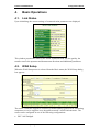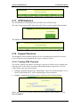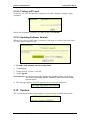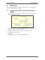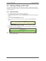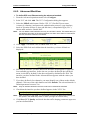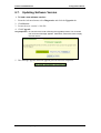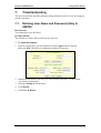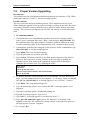
1
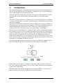
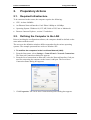
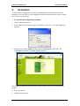
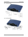
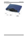
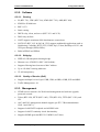
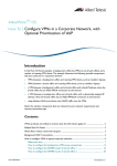
B-FOCuS™ 270/285/400PR Router Configuration Manual www.ecitele.com B-FOCuS 270/285/400 PR Configuration Manual Copyright by ECI Telecom 2001-2003. All rights reserved worldwide. The information contained in this document is proprietary and is subject to all relevant copyright, patent and other laws protecting intellectual property, as well as any specific agreement protecting ECI rights in the aforesaid information. Neither this document nor the information contained herein may be published, reproduced or disclosed to third parties, in whole or in part, without the express, prior, written permission of ECI. In addition, any use of this document or the information contained herein for any purposes other than those for which it was disclosed is strictly forbidden. ECI reserves the right, without prior notice or liability, to make changes in equipment design or specifications. Information supplied by ECI is believed to be accurate and reliable. However, no responsibility is assumed by ECI for the use thereof nor for the rights of third parties, which may be effected in any way by the use thereof. Any representation(s) in this document concerning performance of ECI product(s) are for informational purposes only and are not warranties of future performance, either express or implied. ECI standard limited warranty, stated in its sales contract or order confirmation form, is the only warranty offered by ECI in relation thereto. This document may contain flaws, omissions or typesetting errors; no warranty is granted nor liability assumed in relation thereto unless specifically undertaken in ECI sales contract or order confirmation. Information contained herein is periodically updated and changes will be incorporated into subsequent editions. If you have encountered an error, please notify ECI. All specifications are subject to change without prior notice. ECI Telecom Ltd. Proprietary 2 B-FOCuS 270/285/400 PR Configuration Manual Table of Contents 1. Introduction............................................................................................................5 2. Preparatory Actions ..............................................................................................7 2.1. Required Infrastructure.........................................................................................7 2.2. Defining the Computer in the LAN........................................................................7 3. Activation ...............................................................................................................9 4. Basic Operations .................................................................................................11 4.1. Link Status..........................................................................................................11 4.2. WAN Setup.........................................................................................................11 4.2.1. RFC 1483 Bridged ..................................................................................12 4.2.2. RFC 1483 Routed...................................................................................12 4.2.3. PPP Over Ethernet .................................................................................13 4.2.4. PPP Over ATM .......................................................................................13 4.2.5. Adding, Editing and Deleting Configurations ..........................................13 4.3. LAN Setup ..........................................................................................................14 4.4. Routing Setup.....................................................................................................14 4.5. Save & Reboot ...................................................................................................15 4.6. Erase & Reboot ..................................................................................................16 5. Advanced Operations .........................................................................................17 5.1. ADSL Mode ........................................................................................................17 5.2. DHCP .................................................................................................................17 5.2.1. The Router as a DHCP Server ...............................................................17 5.2.2. The Router as a DHCP Relay.................................................................18 5.3. Firewall ...............................................................................................................18 5.3.1. Users Control ..........................................................................................19 5.3.2. Access Control List (ACL).......................................................................20 5.3.3. Proxy.......................................................................................................21 5.3.4. IP Level Filtering .....................................................................................22 5.4. NAPT ..................................................................................................................24 5.4.1. Static IP address in WAN........................................................................25 5.4.2. Static Mapping of IP Addresses..............................................................25 5.4.3. Static Mapping of Port Numbers .............................................................26 5.5. Configure ............................................................................................................27 5.5.1. Defining Interface Parameters ................................................................27 5.5.2. Defining Virtual Channels .......................................................................30 5.5.3. Defining PPPoE ......................................................................................31 5.5.4. Defining PPPoA ......................................................................................31 5.6. IGMP Proxy ........................................................................................................32 5.7. Bridging ..............................................................................................................33 5.7.1. Bridge Parameters ..................................................................................33 5.7.2. Spanning Tree ........................................................................................34 5.7.3. Defining Filtering.....................................................................................35 5.8. Defining Time and Date......................................................................................36 5.9. Firewall Statistics................................................................................................37 5.10. System Statistics ................................................................................................38 5.11. ATM Statistics.....................................................................................................39 ECI Telecom Ltd. Proprietary 3 B-FOCuS 270/285/400 PR Configuration Manual 5.12. Support Services ................................................................................................39 5.12.1. Testing ATM Channels ...........................................................................39 5.12.2. Testing at IP Level ..................................................................................40 5.12.3. Updating Software Version .....................................................................40 5.13. Version ...............................................................................................................40 6. Workflows ............................................................................................................41 6.1. Changing User Name and Password (only in 400PR) .......................................41 6.2. Defining a Bridge per RFC 1483 ........................................................................42 6.2.1. Basic Workflow .......................................................................................42 6.2.2. Advanced Workflow ................................................................................43 6.3. Defining a Routed IPoA per RFC 1483 ..............................................................45 6.3.1. Basic Workflow .......................................................................................45 6.3.2. Advanced Workflow ................................................................................45 6.4. Defining Classical IPoA per RFC 1577...............................................................47 6.5. Defining PPP Over ATM .....................................................................................49 6.5.1. Basic Workflow .......................................................................................49 6.5.2. Basic Workflow .......................................................................................50 6.6. Defining PPP Over Ethernet...............................................................................51 6.6.1. Basic Workflow .......................................................................................51 6.6.2. Advanced Workflow ................................................................................52 6.7. Updating Software Version.................................................................................53 7. Troubleshooting ..................................................................................................55 7.1. Defining User Name and Password (Only in 400PR) .........................................55 7.2. Proper Version Upgrading ..................................................................................56 7.3. Hardware Reset..................................................................................................57 8. Specifications ......................................................................................................59 8.1. Connection Diagrams .........................................................................................59 8.1.1. B-FOCuS 270 Connections ....................................................................59 8.1.2. B-FOCuS 285PR Connections ...............................................................60 8.1.3. B-FOCuS 400PR Connections ...............................................................60 8.2. Indicators ............................................................................................................61 8.2.1. B-FOCuS 270PR ....................................................................................62 8.2.2. B-FOCuS 285PR ....................................................................................62 8.2.3. B-FOCuS 400PR ....................................................................................63 8.3. Specifications .....................................................................................................64 8.3.1. Standard Compliance .............................................................................64 8.3.2. Software..................................................................................................65 8.3.3. Management...........................................................................................65 8.3.4. Security...................................................................................................66 8.3.5. Physical Interface ...................................................................................66 8.3.6. Environment............................................................................................66 8.3.7. Power......................................................................................................67 8.3.8. Compliance.............................................................................................67 ECI Telecom Ltd. Proprietary 4 B-FOCuS 270/285/400 PR 1. Configuration Manual Introduction This manual describes the configuration procedures performed after installing the BFOCuS 270/285/400PR router. The manual is intended for use by skilled technicians with a solid background in telecommunications. The B-FOCuS router enables the connection of computers interconnected by a local area network (LAN) to the Wide Area Network (WAN) via an ADSL dial-up network. The FOCuS 270PR router has one Ethernet port. It can be connected to one computer or to up to 128 computers, by means of an Ethernet hub. The Ethernet port rate can be either 10 or100Mbps. The FOCuS 285PR router resembles the FOCuS 270PR router, but has an additional USB link (so you can connect it to two computers).The FOCuS 400PR router has an internal Ethernet hub with four ports. It can connect up to four computers to a common ADSL line. The Ethernet ports rates can be either 10 or100Mbps. The router can be installed either as a bridge (in layer 2 of the Communication model) or as a router (in layer 3 of the Communication model). It contains an internal dialer, as well as additional services, such as Dynamic Host Configuration Protocol (DHCP), Network Address Translation (NAT) and Firewall. The configuration software is burned into a flash memory. You can modify it to your needs according to the type of local network, the type of telephony infrastructure and the agreements you made with the suppliers of telephony and Internet services. The following figure describes a typical connection of the B-FOCuS 400PR router to the LAN and the WAN. The router routes the traffic among these networks. By definition, the IP address of each new router at the eth0 port at the LAN side is 192.168.1.1 and the subnet mask is 255.255.255.0. These definitions can be modified as part of the configuration. This manual describes all the configuration user interface features. It also presents typical workflows of using the configuration definition interface. ECI Telecom Ltd. Proprietary 5 B-FOCuS 270/285/400 PR ECI Telecom Ltd. Proprietary Configuration Manual 6 B-FOCuS 270/285/400 PR 2. Preparatory Actions 2.1. Required Infrastructure Configuration Manual To be connected to the router, the computer requires the following: • CPU: At least 266MHz. • An Ethernet Network Interface Card: Either 10Mbps or 100Mbps. • Operating System: Windows 98, NT, ME, 2000 or XP, Unix or Macintosh. • Browser: Internet Explorer, version 5.5 and above. 2.2. Defining the Computer in the LAN Prior to invoking the configuration software, the computer should be defined on the same subnet with the router. The access to the definition windows differs somewhat for the various operating systems. The example presented here refers to Windows XP. To redefine the computers in the Local Area Network (LAN): 1. From the Start menu, select Settings > Control Panel > Network Connections. The Network Connections dialog box appears. 2. From the list of connections to networks, select the Network Interface Card you used for connecting the computer to the router’s eth0 port. The Local Area Connection Status dialog box appears. 3. Click Properties. The Local Area Connection Properties dialog box appears. ECI Telecom Ltd. Proprietary 7 B-FOCuS 270/285/400 PR Configuration Manual 4. Check that the name of the Network Interface Card you used for connecting the computer to the router’s eth0 port appears in the Connect using field. Select Internet Protocol (TCP/IP) and then click Properties. The Internet Protocol (TCP/IP) Properties dialog box appears. 5. Select the Use the following IP address radio button. Define a unique IP address for the computer, in the same subnet where the router is defined (its format should be 192.168.1.n, where n is a unique integer from 2 to 255). In the Subnet mask field, enter 255.255.255.0. In the Default gateway field, enter 192.168.1.1 (the router’s IP address. 6. Click OK. The Local Area Connection Properties dialog box reappears. 7. Click OK. The Local Area Connection Status dialog box reappears. 8. Click Close to close the definition dialog box. ECI Telecom Ltd. Proprietary 8 B-FOCuS 270/285/400 PR 3. Configuration Manual Activation To activate the configuration software, you should first connect the router to the computer (or to the LAN), to the telephony network and to the electric power system (see Connection Diagram). To activate the configuration software: 1. Open an Internet browser. 2. In the address line enter the router’s IP address: 192.168.1.1. A login dialog box appears. 3. Enter the user name: admin and the password: Bezeqwow. Click OK. The configuration software’s opening window appears. The menus are displayed at the left side of the window. They are divided into two groups: • Basic operations. • Advanced operations. ECI Telecom Ltd. Proprietary 9 B-FOCuS 270/285/400 PR Configuration Manual The display on the right side of the window differs according to the menu selection on the left side. The display presents the default router parameters. Configurable fields can be used to modify the initial settings for customizing the router to specific needs. ECI Telecom Ltd. Proprietary 10 B-FOCuS 270/285/400 PR 4. Basic Operations 4.1. Link Status Configuration Manual Upon initializing, the current settings of communication parameters are displayed. This window presents the status of the ADSL communication, the line quality, the transfer rates in the upstream and downstream directions and additional parameters. 4.2. WAN Setup When the WAN Setup menu is selected from the Basic menu, the WAN Setup dialog box appears. The router’s software supports a collection of transformation protocols for connecting computers to service suppliers over the public network’s ADSL infrastructure. The router can be configured in one of the following configurations: • RFC 1483 Bridged. ECI Telecom Ltd. Proprietary 11 B-FOCuS 270/285/400 PR • RFC 1483 Routed. • PPPoE (PPP over Ethernet). • PPPoA (PPP over ATM). • MER (currently not applicable). Configuration Manual A newly installed router is configured as RFC 1483 bridged. In the following sections, we will explain how this default setting can be modified. As a first step, Permanent Virtual Circuits (PVC) and Virtual Channel Connection (VCC) should be defined in the ATM network. This definition is performed at the top of the WAN Setup dialog box. Define: • VPI within the range of 0 to 255. • VCI within the range of 0 to 65535. • The type of encapsulation, either LLC/SNAP or Vc Multiplexing. • Whether NAT is supported. At the bottom of the WAN Setup dialog box there is a table showing current definitions. You can add, remove or edit lines. In order to apply the new or updated definitions to the router, you must save the definitions made via the configuration software to the router’s flash memory and then reboot it. 4.2.1. RFC 1483 Bridged In this configuration, Ethernet frames are bridged over ATM virtual channels. The Ethernet frames are encapsulated using either the LLC/SNAP or Vc Multiplexing method. The router is only responsible for transferring the frames between the LAN and the Internet service provider. If the router’s DHCP server is activated, it assigns IP address to the computers for communication with the WAN. If the DHCP server is not activated, IP addresses are dynamically supplied by the Internet Service Provider (ISP). NAPT and Firewall are not supported. 4.2.2. RFC 1483 Routed In this configuration, IP packets are routed over ATM virtual channels. The Ethernet frames are encapsulated using either the LLC/SNAP or Vc Multiplexing method. The router is only responsible for transferring the packets between the LAN and the Internet service provider. If the router’s DHCP server is activated, it assigns IP addresses to the computers for communication with the WAN. If the DHCP server is not activated, a dummy IP address is assigned to each computer by itself, and this address can be used for communication with the WAN. In addition, an internal DHCP server and NAPT can be used for translating IP addresses between the WAN and the LAN (to avoid exposing the local addresses). ECI Telecom Ltd. Proprietary 12 B-FOCuS 270/285/400 PR Configuration Manual 4.2.3. PPP Over Ethernet In this configuration, additional management services can be activated, like authentication and efficient bandwidth management (by closing inactive sessions). Additional parameters should be defined: • User name, password and authentication protocol (in most of the cases PAP is used). • Whether the call is connected constantly (Direct) or the connection is established only when real communication activity with the WAN is performed (Auto). • In Auto state, define the length of idle time after which the call is disconnected. In PPP configuration, IP addresses for accessing the WAN are supplied by the ISP to the router. When the router is activating the internal DHCP, it supplies IP addresses to the computers in the LAN. This must be done to enable surfing the Internet from a computer in the LAN. In addition, NAPT must be activated to translate IP addresses between the LAN and the WAN. 4.2.4. PPP Over ATM In this configuration, authentication services can be activated. These additional parameters should be configured: user name, password and authentication protocol. In PPP configuration, IP addresses for accessing the WAN are supplied by the ISP to the router. When the router is activating the internal DHCP, it supplies IP addresses to the computers in the LAN. This must be done to enable surfing the Internet from a computer in the LAN. In addition, NAPT must be activated to translate IP addresses between the LAN and the WAN. 4.2.5. Adding, Editing and Deleting Configurations To add a new configuration: 1. Select the radio button representing the required configuration. 2. Modify the required parameters at the top of the WAN Setup dialog box. 3. Modify the required parameters in the area relevant to the selected configuration. 4. Click Add. 5. Check that the new configuration appears in the table at the bottom of the dialog box. To edit a configuration: 1. Select the line you want to edit from the table at the bottom of the dialog box. 2. Modify the required parameters at the top of the WAN Setup dialog box. 3. Modify the required parameters in the area relevant to the selected configuration. 4. Click Modify. 5. Check that the changes are reflected in the table at the bottom of the dialog box. ECI Telecom Ltd. Proprietary 13 B-FOCuS 270/285/400 PR Note: Configuration Manual You cannot change the VCI and VPI values using the Modify command. Instead, delete the old line from the table at the bottom of the dialog box and add a new line with the new parameters. To delete a configuration: 1. Select the line you want to delete from the table at the bottom of the dialog box. 2. Click Delete. 3. Check that the line is deleted from the table at the bottom of the dialog box. 4.3. LAN Setup When the LAN Setup menu is selected from the Basic menu, the LAN Setup dialog box appears: Define the IP address and subnet mask of the router towards the LAN (port eth0) and click Apply. 4.4. Routing Setup When the Routing Setup menu is selected from the Basic menu, the Routing Setup dialog box appears. The table displays all the routers recognized in the network. It contains both static routing lines that can be edited (added, edited, deleted) and dynamic routing lines, generated dynamically by the router’s communication protocol. The routing table defines through which port each packet is sent, according to its specified destination. ECI Telecom Ltd. Proprietary 14 B-FOCuS 270/285/400 PR Configuration Manual After a new router is installed, the RIP protocol is set by default to Off. To activate it, the status must be changed to On. In addition, you can define the RIP version to be used. For additional information concerning the RIP protocol, click RIP Information. The RIP List window appears. This list appears for the B-FOCuS 270/285PR. This list appears for the B-FOCuS 400PR. 4.5. Save & Reboot When a new configuration has been defined, it must be burned into the router’s internal flash memory. Then the router must be restarted. The new configuration becomes effective only after it has been saved and the router has been restarted. When selecting Save & Reboot from the Basic menu, the following dialog box appears. Click Save. When an acknowledgement is received, click Reboot. ECI Telecom Ltd. Proprietary 15 B-FOCuS 270/285/400 PR 4.6. Configuration Manual Erase & Reboot If you want to return to the default configuration settings, you must erase the changes you have made and restart the computer. The default configuration becomes effective only after the reboot. When selecting Erase & Reboot from the Basic menu, the following dialog box appears. Click Erase first. When an acknowledgement is received, click Reboot. ECI Telecom Ltd. Proprietary 16 B-FOCuS 270/285/400 PR 5. Advanced Operations 5.1. ADSL Mode Configuration Manual When selecting ADSL Mode from the Advanced menu, this dialog box appears. Currently only G.DMT is supported. 5.2. DHCP The DHCP protocol enables dynamic allocation of IP addresses for efficient use of the address reservoir. The router can operate in two modes: • As a server (allocating addresses to computers in the LAN). • As a relay (relaying the request from the LAN to a specific DHCP server at the WAN). When one mode of operation is selected, the second mode becomes inactive. Note: When there is a DHCP in the LAN, port eth0 can be defined as a client and receive an IP address from it. This mode can be configured using the Configure option in the Advanced menu. See Configure. 5.2.1. The Router as a DHCP Server The DHCP tab enables defining parameters when the router is configured as a DHCP server. Each line can be used to define a range of IP addresses to be allocated to each sub-network. Initially, each new line is in Stop mode. To activate it, select it and click the Start button (it immediately toggles itself to Stop). The router will implement the new definitions only after Save and Reboot are applied. To add a new line: 1. Click Add. The DHCP Server Configuration dialog box appears. ECI Telecom Ltd. Proprietary 17 B-FOCuS 270/285/400 PR Configuration Manual 2. Define: • Interface. Only eth0 is supported, as the router acts as a DHCP Server towards the LAN. • IP address range for allocation in the LAN. • Default gateway (the router’s IP address towards the LAN). • Subnet mask. • IP address of the Domain Name Server (DNS). Since the DNS resides in the WAN, enter the IP address of the default gateway used to access the WAN. • The number of days for leasing the address. 3. Click Apply. 4. Perform Save & Reboot. 5.2.2. The Router as a DHCP Relay To define the router as a DHCP relay: 1. Define the address of the DHCP in the WAN. 2. Change the DHCP Relay mode to Enable. 3. Click Apply. 4. Perform Save & Reboot. 5.3. Firewall The firewall filters the traffic between the LAN and the WAN. Logically, it is positioned before the router in the WAN, to filter the downstream traffic arriving from the Internet and before the router in the LAN, to filter the upstream traffic from the LAN towards the Internet. ECI Telecom Ltd. Proprietary 18 B-FOCuS 270/285/400 PR Configuration Manual The filtering is performed by defining users (of the router’s services); assigning for each user access permissions to the router and to the WAN; and defining filtering rules that apply to certain users and certain types of traffic. 5.3.1. Users Control The Access Control tab is used to define the router’s users and to control the permissions for accessing the router itself and the WAN via the router. Three users are defined by default: • admin is a user permitted to perform all the available definitions. In addition, he can use CLI (Telnet), HTTP or FTP to access the configuration user interface. To login as an administrator, use the user name: admin and the password: Bezeqwow (see Activation). • Pppoa and pppoe are users with administrator’s permissions, but they can access the configuration user interface only via HTTP. An administrator (as defined in the Permissions field), can add, modify and delete all the router’s parameters. An ordinary user can only view parameters defined by default or by the administrator. To add a new user: 1. Click Add, The User Configuration dialog box appears. 2. Define user name, password, access services and permissions. The length of the password should be at lease 16 characters. 3. Click Apply. To delete a user: 1. Select the required user using the radio button. ECI Telecom Ltd. Proprietary 19 B-FOCuS 270/285/400 PR Configuration Manual 2. Click Delete. To modify the parameters of an existing user: 1. Select the required user using the radio button. 2. Click Modify. The User Modification dialog box appears. 3. Modify the required parameters (user name, password, access services and permissions) and click Apply. To change the user’s password: 1. Select the required user using the radio button. 2. Click Change Password. The Change Password dialog box appears. 3. Enter the old password and the new password (twice). The length of the password should be at least 16 characters. 4. Click Apply. 5.3.2. Access Control List (ACL) This tab enables control over the traffic to and from the LAN. The control is performed by a proxy. The proxy must be defined both in the computer (using the browser’s software) and in the router (see Proxy). The proxy serves as a gatekeeper to the LAN. When a user wants to access the Internet via the router, it should first pass through the proxy, and then the ACL is applied. Note: The router’s restrictions are only implemented for HTTP proxy. ECI Telecom Ltd. Proprietary 20 B-FOCuS 270/285/400 PR Configuration Manual The ACL List displays the defined access rules. To add a new rule definition: 1. Click Add. The Access List Configuration dialog box appears. 2. Select whether you want to apply the rule to specific users (from the list of users defined at the Access Control tab) or to all users. If you check the User Name checkbox, you must define a specific user. Otherwise, the rule applies to all users. 3. Define these parameters: • The priority of this rule relative to other rules. • Destination address in the WAN. • IP address range in the LAN. • Domain name. • The applications to which the rule applies (for example: Audio All blocks downloading audio files). • Time range over which the rule applies (within a weekly frame). • Whether the defined traffic should be blocked or allowed. 4. To add the rule to the ACL list, click Apply. 5.3.3. Proxy The Proxies tab enables authentication of each user who tries to access the WAN from the LAN. ECI Telecom Ltd. Proprietary 21 B-FOCuS 270/285/400 PR Configuration Manual As a default, the proxy and the authentication process are disabled. If you want to apply the ACL rules, you must enable the proxy. Note: The proxy must be defined in the router as well as in all the LAN computers. 5.3.4. IP Level Filtering As a default, the firewall enables opening any session from the LAN to the WAN, but no session in the opposite direction. The traffic filtering is performed by rules (Policies) that are applied to it in a prioritized order. When a new package appears, the firewall checks whether the top priority rule applies to it. If it does, a decision is made whether to transfer or to block it (in accordance with the rule). If it does not apply, the next prioritized rule is applied, and so on, until the end of the list. The List of Firewall Policies presents the defined rules. Note that the priority is higher as the Precedence number is lower. Each rule has a unique identifier called FW Action ID. As a default, the rules presented in the figure (30000, 29000 and 20000) are applied. These rules cannot be deleted, yet they can be copied and assigned with lower priority. To add a new rule: 1. Click Add. The Firewall Configuration dialog box appears. ECI Telecom Ltd. Proprietary 22 B-FOCuS 270/285/400 PR Configuration Manual 2. Define the rule’s parameters: • Precedence (an integer from 1 to 64K). • Source IP address and subnet mask. • Destination IP address and subnet mask. • Source port range. • Destination port range (use the list). • Protocol. • When TCP is selected, you may define also specific flags. 5. Apply the rule to the traffic via the firewall. You can do this in one of two ways: • • Define a new Action ID. In this case you should define: • An interface (selected from the list). • The direction of traffic relative to the WAN (“In” refers to Upstream – from LAN to WAN, “Out” refers to Downstream – from WAN to LAN). • The action applied to the specified traffic – Allow or Deny. • Time range for the rule’s application. Apply an existing Action ID. ECI Telecom Ltd. Proprietary 23 B-FOCuS 270/285/400 PR Configuration Manual In this case, enter the number of an existing Action ID. The rule’s application parameters are copied from the original definition. You can redefine the precedence to apply this rule at a higher priority. 6. Click Apply. To view the rules you have defined: In the IP Filtering tab click View Actions. The List of Firewall Parameters dialog box appears. You can see the parameters common to all rules having the same Action ID. 5.4. NAPT The Network Address Port Translation (NAPT) protocol translates IP addresses from LAN to WAN and vice versa. This is performed for efficient use of the IP address range and for protection of privacy. Each package contains in its header the addresses of the source and the destination. In addition, it contains the identity of source and destination ports. This information is required to identify the application that has generated the data (such as: HTTP, FTP, Telnet, Yahoo Messenger). The NAPT service is characterized by two IP addresses: one towards the WAN and the other towards the LAN. From the WAN side, all the LAN computers reside under the same address. When a computer in the LAN initiates access to the WAN, the ECI Telecom Ltd. Proprietary 24 B-FOCuS 270/285/400 PR Configuration Manual NAPT translates its IP address and port number to other values. When the answer arrives from the WAN, the NAPT server knows how to route it to the originating computer. From the WAN side it is impossible to initiate access to a specific computer within the LAN, unless the proper permissions have been defined. The router supports three modes of operation: • Static IP address in WAN. • Mapping address from WAN to LAN. • Mapping port numbers from WAN to LAN. 5.4.1. Static IP address in WAN You can define a static IP address for the router, from the WAN side. The address is received from the ISP. To add a new line, click Add. The Static WAN Address Configuration dialog box appears. Enter the IP address you have received from the ISP and click Apply. 5.4.2. Static Mapping of IP Addresses Static mapping of IP addresses enables access from the WAN to the LAN, while preserving privacy. The static mapping list presents the router’s IP address towards the WAN and the range of IP addresses to be allocated to the LAN’s computers by the internal DHCP. A few lines can be used to map a few internal IP address ranges to a few WAN addresses. ECI Telecom Ltd. Proprietary 25 B-FOCuS 270/285/400 PR Configuration Manual To add a line to the list: 1. Click Add. The Static NAT Configuration dialog box appears. 2. Define the IP address towards the WAN and the IP addresses range for allocation in the LAN. Note: To enable traffic from the WAN to the LAN, define the same IP address in the Local Address From and in the Local Address To fields. In addition, open the applicable port in the Firewall (see IP Level Filtering ). 3. Click Apply. 5.4.3. Static Mapping of Port Numbers Static mapping of port numbers enables access from the WAN to the LAN while preserving privacy. The static mapping list shows the router’s IP address for the WAN, the IP address for the LAN and the port’s range for traffic from the WAN to the LAN. A few lines can be used to map a few port ranges in the WAN to a few internal IP addresses in the LAN. To add a line to the list: 1. Click Add. The Port Range Configuration dialog box appears. ECI Telecom Ltd. Proprietary 26 B-FOCuS 270/285/400 PR Configuration Manual 2. Define the public address, the public port range, the local address, the local port range and the layer 4 protocol (UDP or TCP). 3. Click Apply. Note: 5.5. In addition to these definitions, open the applicable port in the Firewall (see IP Level Filtering ). Configure The Configure menu enables detailed definition of the communication parameters in various sessions. You can see a summary table of all the interface definitions as well as the parameters of each interface separately. 5.5.1. Defining Interface Parameters The List of Interface Entries table in the Interface tab summarizes the parameters of all the definable interfaces. • eth0 – is the interface towards the LAN. ECI Telecom Ltd. Proprietary 27 B-FOCuS 270/285/400 PR Configuration Manual • mer0 – is not applicable. • adsl0 - is the interface towards the WAN (not definable). • lo0 – is the loop-back interface (not definable). • atm0-atm7 - are the interfaces for IOPA networks. • pppo-ppp7 – are the interfaces for the internal dialer within the router (not definable). The values presented in the above figure are the default values. At the bottom of the tab there are control buttons that enable operations on the displayed data. To configure the eth0 interface: 1. Select the radio button on the eth0 line and click Configure Interface. The Ethernet Interface Configuration dialog box appears. 2. Select the mode of defining the IP address – static or dynamic – from the DHCP server. 3. If the IP address is set to static mode, defined these parameters: • IP address and subnet mask. • Maximum size of a package (MTU). • Communication rate (auto, 10Mbps, 100Mbps). • Communication type (auto, half duplex, full duplex). 4. To activate the interface set the status to UP. 5. Click Apply. To configure the ATM Interface: 1. Select the radio button on the required line and click Configure Interface. The ATM Interface Configuration dialog box appears. ECI Telecom Ltd. Proprietary 28 B-FOCuS 270/285/400 PR Configuration Manual 2. Define: • IP address and subnet mask. • Maximal size of a package (MTU). 3. To activate the interface set the status to UP. 4. Click Apply. To define DNS and Default Gateway to all interfaces: 1. Select the radio button on the required line and click DNS & Default G/W. The DNS & Default Gateway Configuration dialog box appears. 2. Define: • Domain name in the WAN. • Primary and secondary DNS in the WAN. • IP address of the default gateway for accessing the WAN. 3. Click Apply. Note: As a default, the router is defined as the relay of the ISP parameters towards the LAN. To define a NAT for the ATM and PPP Interfaces: 1. Select NAT. The NAT Configuration dialog box appears, 2. Select an interface from the list and check the Enable NAT checkbox. 3. Click Apply. Note: NAT can be enabled only on active interfaces. ECI Telecom Ltd. Proprietary 29 B-FOCuS 270/285/400 PR Configuration Manual 5.5.2. Defining Virtual Channels The VCC tab displays the defined virtual channels. To see virtual channels in the IPoA network: Click List Ipoa. To Delete the encapsulation in a specific channel: Select the required radio button and click Delete Encap. To add a new Channel: 1. Click Add. The VCC Configuration dialog box appears. 2. This dialog box resembles the WAN Setup dialog box in the Basic Operations menu, yet it enables more detailed definitions. For example: traffic shaping parameters such as Peak Cell Rate, CDVT, traffic type (voice or data) and service type (CBR, UBR, NRTVBR, RTVBR). 3. Select the required protocol and define its parameters. 4. Click Apply. Note: If no radio button is selected, the default is EoA. ECI Telecom Ltd. Proprietary 30 B-FOCuS 270/285/400 PR Configuration Manual To view ATM parameters: Click Show VCC Quality. A list of VCCs and their parameters appears. 5.5.3. Defining PPPoE The PPPoE tab displays detailed parameters of the dial-up over Ethernet channels. Note that the table’s header consists of two lines, and two lines of data are displayed accordingly for each channel. A few channels can be defined simultaneously, and then one of them can be selected as a default. Each channel can be started and stopped individually using the Start and Stop buttons. Starting a channel activates dial-up from the router to the public network. 5.5.4. Defining PPPoA The PPPoA tab displays detailed parameters of the dial-up over ATM channels. Note that the table’s header consists of two lines, and two lines of data are displayed accordingly for each channel. A few channels can be defined simultaneously, and then one of them can be selected as a default. Each channel can be started and stopped individually using the Start and Stop buttons. Starting a channel activates dial-up from the router to the public network. ECI Telecom Ltd. Proprietary 31 B-FOCuS 270/285/400 PR 5.6. Configuration Manual IGMP Proxy The IGMP Proxy is used for transferring video and television channels over telephony infrastructure. You can see a summary table of all the interface definitions as well as the parameters of each interface separately. The IGMP-Proxy is configured on WAN interfaces. The IGMP-Proxy-router is configured on any available LAN interface. The IGMP-Proxy-Router periodically sends a query over all of the interfaces that are configured as IGMP-Proxy-Router interfaces. It does so in order to determine which groups have members on IGMPProxy-Router interfaces. The IGMP-Proxy-Router receives IGMP reports from IGMP hosts and maintains a list of group membership for each IGMP-Proxy-Router interface. If the IGMP-ProxyRouter finds a "new multicast group join," it will send an IGMP join report to the Multicast Router over the IGMP-Proxy interface. When the IGMP-Proxy-Router receives an IGMP leave report, it sends a group-specific query over the IGMP-ProxyRouter interfaces. If it doesn't receive any response to that group-specific query, and the WAN Multicast Router type is Version 2,then the IGMP-Proxy sends a leave report to the WAN Multicast Router over the IGMP-Proxy interface. After the IGMP-Proxy receives a general query from the WAN Multicast Router, the IGMP-Proxy starts timers for all registered multicast groups. Once timers expire, it will send a group-specific report to the WAN Multicast Router over the IGMP-Proxy interface. When the IGMP-Proxy receives the IGMP report for a specific group, the IGMPProxy stops the timer for that specific group and doesn’t send.an IGMP report for that specific group to the WAN Multicast Router. To add a new interface: 1. Click Add. The IGMP Proxy Configuration dialog box appears. 2. Define the proxy interface and the router interface and click Apply. ECI Telecom Ltd. Proprietary 32 B-FOCuS 270/285/400 PR 5.7. Configuration Manual Bridging Ethernet frames are bridged over ATM virtual channels (per RFC 1483). The frames are encapsulated either in LLC mode or in Vc Multiplexing mode. The Bridging menu enables viewing and defining the router’s parameters, when operated as a bridge. 5.7.1. Bridge Parameters The Bridge tab displays the defined bridge parameters. To delete an existing bridging group: Click Flush. To define a group of interfaces as a bridging group: 1. Click GroupInfo. The Group Interfaces dialog box appears. 2. Check the interfaces you want to include in the group and click Apply. To define an interface and an encapsulation type to an open PVC: 1. Click AddPVC. The Bridge Configuration dialog box appears. ECI Telecom Ltd. Proprietary 33 B-FOCuS 270/285/400 PR Configuration Manual 2. Select an interface from the list. You can only select interfaces that have previously been defined as members of the bridging group. 3. Define virtual channels (Vpi and Vci). 4. Select the type of encapsulation. 5. Click Apply. 6. Check that the interface has been added to the list. To delete an existing bridging group: Click Flush. To activate the defined bridge entries: Click Enable. Note: The workflow is as follows: Define an EoA configuration. Click Flush. Define a bridging group. Add an interface. Click Enable. Finally open the Configure menu and validate that the status of all the interfaces defined within the group is Bridged. 5.7.2. Spanning Tree The Spanning Tree tab presents the definition of links within the tree: links to bridges in the WAN, the state of transfer, priority and cost. To see additional parameters: Click STP Parameters. A list of Spanning Tree parameters appears. To modify the values of some parameters: 1. Click Config Port. The Port Configuration dialog box appears. ECI Telecom Ltd. Proprietary 34 B-FOCuS 270/285/400 PR Configuration Manual 2. Define the required port parameters and click Apply. To activate the definition Click Enable. 5.7.3. Defining Filtering The Filters tab presents the filtering parameters of Ethernet nodes. For every node in the tree (defined by means of a MAC address of a communication unit in the network), you can define the filtering parameter – whether data arriving from this node towards the WAN will be blocked or passed. The default is Dynamic, enabling passage from all nodes via the eth0 interface. If you block the passage from some nodes, the parameter in the Age column is changed to Static. Note: You cannot modify a line whose Age parameter is Dynamic. You can only add a similar line (referring to the same MAC address) whose age parameter is Static. Both lines are displayed, but the Static line has higher priority. To view more details: Click Filter Parameters. The List of Filter Parameters appears. To add filtering definitions: 1. Click Add. The Filter Configuration dialog box appears. ECI Telecom Ltd. Proprietary 35 B-FOCuS 270/285/400 PR Configuration Manual 2. Define the MAC address and Frame (Forward or Block). Click Apply. To modify filtering definitions: 1. Use the radio button to select the node you want to modify and click Modify. The Filter Configuration dialog box appears. 2. Modify the MAC address and define Frame (Forward or Block). Click Apply. To delete filtering definitions: Use the radio button to select the node you want to delete and click Delete. Note: 5.8. You cannot delete Dynamic definitions for eth0, which is the default. Defining Time and Date To apply time dependent rules, the router must be synchronized with local timing. For example: firewall blocking rules can change according to business hours. The Time & Date menu enables configuring the router with local parameters. Note: The router’s clock advances only when the router is running. Therefore, it is recommended to update this parameter when the router is restarted. ECI Telecom Ltd. Proprietary 36 B-FOCuS 270/285/400 PR 5.9. Configuration Manual Firewall Statistics The Firewall Statistics menu presents data for traffic that has passed via the firewall or has been blocked. The Traffic tab displays statistics for all sessions that have reached the firewall. The HTTP tab displays only sessions in the HTTP proxy protocol, sorted by the users that have initiated them. ECI Telecom Ltd. Proprietary 37 B-FOCuS 270/285/400 PR Configuration Manual 5.10. System Statistics The System Statistics menu presents general data on the system in which the router operates. The Interface tab displays general data about all interfaces, their statuses and the traffic that has passed through them. The TCP/IP tab displays data on the traffic in the IP, UDP, TCP and ICMP protocols. The DHCP tab displays data concerning IP addresses allocated by the router’s DHCP server, the connection and disconnection times and the MAC address of the connected computer. ECI Telecom Ltd. Proprietary 38 B-FOCuS 270/285/400 PR Configuration Manual 5.11. ATM Statistics The ATM Statistics tab displays data for traffic in the ATM network. The AAL5 tab presents traffic data at the AAL5 layer, used to transfer data channels. The SNDCP tab presents encapsulation data. 5.12. Support Services The Diagnostics menu enables support services, including the activation of various levels of fitness tests and updating the router’s software version. 5.12.1. Testing ATM Channels The OAM Loopback tab enables activating a connectivity fitness test by sending data from the router to the WAN, receiving it back and making a comparison. Two test (called Flow) types can be performed: • Sending a standard data package (identified by a specific content identifier) over a virtual ATM channel (F5), end-to-end along the selected channel. • Sending a standard data package along a segment of the selected channel. Define the flow type, the tested channel and the loopback content identifier. Click Start Loopback. ECI Telecom Ltd. Proprietary 39 B-FOCuS 270/285/400 PR Configuration Manual 5.12.2. Testing at IP Level At the IP level, you can check the connectivity to other computers using the Ping command. Define the destination computer’s IP address and click Submit. 5.12.3. Updating Software Version When a new version of the router’s software is released, it is sent to you in the form of a file with the extension .bin. To load a new software version to the router: 1. Click Browse. 2. Locate the new version’s *.bin file. 3. Click Upgrade. Very Important: Do not switch the router off during the upgrade process! You must wait until a success message appears. Afterwards, restart the router to apply the new version. 4. This message appears when the upgrade process has been completed. 5.13. Version The Version menu enables displaying the version currently installed in the router. ECI Telecom Ltd. Proprietary 40 B-FOCuS 270/285/400 PR 6. Configuration Manual Workflows This section describes typical workflows for using the B-FOCuS 270/400PR User Interface for performing typical operations. 6.1. Changing User Name and Password (only in 400PR) 1. Login as a PPPoA user, using user name: pppoa and password: user. The PPPoA Configuration dialog box appears. 2. Change the user name to the name received from your ISP. Use the format <user Name>@<domain>. For example: john@ISP. 3. Change the password to the one you have received from your ISP. 4. Check the Enable NAT checkbox. 5. Click Modify. 6. From the Basic operations menu, click Save & Reboot. ECI Telecom Ltd. Proprietary 41 B-FOCuS 270/285/400 PR 6.2. Configuration Manual Defining a Bridge per RFC 1483 You can define a bridge in two ways. The basic workflow is simple, but most of the parameters are defined by default. The advanced workflow enables detailed definition of most parameters. 6.2.1. Basic Workflow To define a bridge per RFC 1483 in the basic way: 1. From the Basic operations menu select WAN Setup. The WAN Setup dialog box appears. 2. Click the RFC 1483 Bridged radio button. 3. In the top line enter the VPI and VCI values and select the LLC/SNAP radio button. 4. At the bottom of the dialog box click Add. 5. Check that a new line, containing the values you have defined, is added to the table at the bottom of the dialog box. Note: When defining a bridge in the basic way, all the channels are opened by default under the atm0 interface. ECI Telecom Ltd. Proprietary 42 B-FOCuS 270/285/400 PR Configuration Manual 6.2.2. Advanced Workflow To define a bridge per RFC 1483 in the advanced way: 1. You have to assign the interfaces you want to define to the bridging group. From the Advanced operations menu select Bridging. 2. Click Flush. 3. In the Bridge tab, click GroupInfo. The Group Interfaces dialog box appears. 4. Check the interfaces you want to add to the group (in this example: etho, atm0, atm1). 5. Click Apply. This line is added to the List of Bridge Entries. 6. To define the bridge, from the Advanced operations menu click Configure. 7. In the VCC tab click Add. The VCC Configuration dialog box appears. As a default, the bridge definition radio button is selected. Enter the VCI and VPI values. Select the service type. Define the traffic shaping parameters. 8. Click Apply. A line is added to the VCC table. ECI Telecom Ltd. Proprietary 43 B-FOCuS 270/285/400 PR Configuration Manual 9. To define the encapsulation, select Bridging from the Advanced menu and click Add PVC. The Bridge Configuration dialog box appears. 10. Select one of the atm interfaces (in this example, atm1). Enter the VCI and VPI values and select the type of encapsulation. 11. Click Apply. The values you have defined appear in the atm line (in this example, atm1). 12. To activate the bridge, click Enable. 13. From the Advanced menu select Configure. Check that the status of all the group members (eth0, atm0, atm1) is Bridged. 14. From the Advanced menu select VCC. Check that all the values you have defined are displayed. ECI Telecom Ltd. Proprietary 44 B-FOCuS 270/285/400 PR 6.3. Configuration Manual Defining a Routed IPoA per RFC 1483 You can define a router in two ways. The basic workflow is simple, but most of the parameters are defined by default. The advanced workflow enables detailed definition of most parameters. 6.3.1. Basic Workflow To define a routed IPoA per RFC 1483 using the basic method: 1. From the Basic operations menu select WAN Setup. The WAN Setup dialog box appears. 2. Click the RFC 1483 Routed radio button. Define VPI, VCI, encapsulation type (LLC/SNAP) and check Enable NAPT. Define a WAN IP address and subnet mask. 3. At the bottom of the dialog box click Add. Check that a line is added to the table containing the values you have defined. 6.3.2. Advanced Workflow To define a routed IPoA per RFC 1483 using the advanced method: 1. From the Advanced menu click Configure. Select the radio button in a line with an available ATM interface (in this example: atm4). 2. At the bottom of the dialog box click Configure Interface. The ATM Interface Configuration dialog box appears. ECI Telecom Ltd. Proprietary 45 B-FOCuS 270/285/400 PR Configuration Manual 3. Define the selected interface, the IP address and subnet mask in the WAN, and the MTU value. Set the status to UP. Click Apply. 4. Check that the newly defined interface appears in the table in the Interface tab and that its status is UP. 5. Select the VCC tab and click Add. The VCC Configure dialog box appears. 6. Click the Routed radio button. Select the interface you want to define (atm4) from the list. Define VPI, VCI and all other parameters. 7. Click Apply. A new line is added to the VCC table. 8. To define NAT, return to the Interface tab and click NAT. The NAT Configuration dialog box appears. 9. Check Enable NAT and select the Interface you want to define (atm4). Click Apply and then click Continue. 10. In the VCC tab, click Show VCC Quality. A list of VCCs appears. Check that it contains the values you have defined. ECI Telecom Ltd. Proprietary 46 B-FOCuS 270/285/400 PR Configuration Manual 11. From the Basic menu select WAN Setup. Check that the channel you have defined appears in Router mode and that NAPT is in the On state. 6.4. Defining Classical IPoA per RFC 1577 Classical IPoA per RFC 1577 can only be done using the Advanced method. To define Classical IPoA: 1. From the Advanced menu select Configure. 2. From the list of interfaces select an available ATM interface (in this example atm5) and click Configure Interface. The ATM Interface Configuration dialog box appears. 3. Define the name of the interface, the IP address and subnet mask in the WAN and the MTU value. Change the status to UP. 4. Click Apply. Check that the definitions appear in the list of interfaces. 5. In the VCC tab click Add. 6. Define the VCC parameters. 7. Select the IPoA radio button. Select the ATM5 interface. ECI Telecom Ltd. Proprietary 47 B-FOCuS 270/285/400 PR Configuration Manual 8. There are two options: • If you check the Default PVC checkbox, you should define specific VC and VP and the traffic shaping parameters. • If you uncheck the Default PVC checkbox, define the next hop IP address – an address in the WAN from which the routing continues. 9. In both cases click Apply. Check that the newly defined interface appears in the VCC list. 10. Click Show VCC Quality and validate that the traffic shaping parameters appear as you have defined them. 11. Click Close to close the pop-up window. 12. To activate NAT, select the Interface tab and click NAT. The NAT Configuration dialog box appears. ECI Telecom Ltd. Proprietary 48 B-FOCuS 270/285/400 PR Configuration Manual 13. Select the interface (atm5). Check the Enable NAT checkbox. Click Apply and then click Continue. 14. Check that the interface you have defined appears in the WAN Setup table with NAPT in the On state. 6.5. Defining PPP Over ATM You can define PPP over ATM in two ways. The basic workflow is simple, but most of the parameters are defined by default. The advanced workflow enables detailed definition of most parameters. 6.5.1. Basic Workflow To define PPP over ATM using the basic method: 1. From the Basic operations menu select WAN Setup. The WAN Setup dialog box appears. 2. Click the PPPoA radio button. Define VPI, VCI and encapsulation type. Note that Enable NAPT is checked by default. Define user name (<name>@<domain>) and password, as received from your ISP and select the PAP authentication protocol. 3. Click Add. Check that a line is added to the table at the bottom of the dialog box. Note that although NAPT is enabled, it appears in the table in the Off state. The state will be changed to On when the router is actually connected to the ISP (after dialing). ECI Telecom Ltd. Proprietary 49 B-FOCuS 270/285/400 PR Configuration Manual 6.5.2. Basic Workflow To define PPP over ATM using the advanced method: 1. From the Advanced operations menu select WAN Configure. 2. In the VCC tab click Add. The VCC Configuration dialog box appears. 3. Select the PPPoA radio button. Define: VPI, VCI, Profile ID, user name (<name>@<domain>) and password, authentication protocol (PAP), a ppp interface, encapsulation type (VC), subnet mask and trace. Enable NAT. Note: You can define a few Profile IDs, but only one of them is active. This means that you can define a few users on the same interface, but when one of them is connected to the ISP, the others cannot be connected. 4. Click Apply. Check that a line is added in the VCC tab. 5. Select the PPPoA tab and check that the interfaces you have defined are displayed. 6. Note that the interface you have defined in the Basic menu appears in ppp0 (the first available ppp interface, before the one you have defined in the Advanced menu is selected by default). It has been assigned by default Profile ID 0. The interface you have defined in the Advanced menu appears with the values you have just defined. 7. If you have defined a few channels, you must identify one of them as the default channel. Click one of the radio buttons and click Default. The selected interface’s Default parameter becomes Yes. ECI Telecom Ltd. Proprietary 50 B-FOCuS 270/285/400 PR Configuration Manual 8. Check that the interface you have defined appears in the VCC list. Note: After connection to the WAN, you will be able to see the IP address allocated by the ISP (either in the WAN Setup menu or when you login as a PPPoA user). 9. Click Show VCC Quality and check that the traffic shaping parameters appear as you have defined them. 6.6. Defining PPP Over Ethernet You can define PPP over Ethernet in two ways. The basic workflow is simple, but most of the parameters are defined by default. The advanced workflow enables detailed definition of most parameters. 6.6.1. Basic Workflow To define PPP over Ethernet using the basic method: 1. From the Basic operations menu select WAN Setup. The WAN Setup dialog box appears. 2. Click the PPPoE radio button. Define VPI, VCI and encapsulation type (LLC). Note that Enable NAPT and Enable DHCP Server are checked by default. Define user name (<name>@<domain>) and password, as received from your ISP and select the PAP authentication protocol. Define the Mode; select Direct if the session is always connected; select Auto and define idle time if the session is disconnected when there is no traffic. 3. Click Add. Check that a line is added to the table. Note that although NAPT is enabled, it appears in the table in the Off state. The state will be changed to On when the router is actually connected to the ISP (after dialing). ECI Telecom Ltd. Proprietary 51 B-FOCuS 270/285/400 PR Configuration Manual 6.6.2. Advanced Workflow To define PPP over Ethernet using the advanced method: 1. From the Advanced operations menu select Configure. 2. In the VCC tab click Add. The VCC Configuration dialog box appears. 3. Select the PPPoE radio button. Define: VPI, VCI, Profile ID, user name (<name>@<domain>) and password, authentication protocol, a ppp interface, mode of operation (Direct or Auto and idle time), encapsulation type (LLC), subnet mask and trace. Enable NAT. Note: You can define a few Profile IDs, but only one of them is active. This means that you can define a few users on the same interface, but when one of them is connected to the ISP, the others cannot be connected. 4. Click Apply. Check that a line is added at the VCC tab. 5. Select the PPPoE tab and validate that the interfaces you have defined are displayed. 6. Note that the interface you have defined in the Basic menu appears in ppp2 (the first available ppp interface, before the one you have defined in the Advanced menu is selected by default). It has been assigned by default Profile ID 0. The interface you have defined in the Advanced menu appears with the values you have defined. 7. If you have defined a few channels, you must identify one of them as the default channel. Click one of the radio buttons and click Default. The selected interface’s Default parameter becomes Yes. Note: Only an interface defined in the Auto mode can be selected as a default. 8. Check that the interface you have defined appears in the VGCC list. Note: After connection to the WAN, you will be able to see the IP address allocated by the ISP (either in the WAN Setup menu or when you login as a PPPoA user). 9. Click Show VCC Quality and check that the traffic shaping parameters appear as you have defined them. ECI Telecom Ltd. Proprietary 52 B-FOCuS 270/285/400 PR 6.7. Configuration Manual Updating Software Version To load a new software version: 1. From the Advanced menu select Diagnostics and click the Upgrade tab. 2. Click Browse. 3. Locate the new version’s *.bin file. 4. Click Upgrade. Very Important: Do not switch the router off during the upgrade process! You must wait until a success message appears. Afterwards, restart the router to apply the new version. 5. This message appears when the upgrade process has been completed. ECI Telecom Ltd. Proprietary 53 B-FOCuS 270/285/400 PR ECI Telecom Ltd. Proprietary Configuration Manual 54 B-FOCuS 270/285/400 PR 7. Configuration Manual Troubleshooting This section describes possible problems arising when the router is used, and suggests possible solutions. 7.1. Defining User Name and Password (Only in 400PR) Phenomenon: You cannot dial up to the WAN. Possible solution: The defined user name and/or password are incorrect. To solve the problem: 1. Login as a pppoa user. Use the default user name: pppoa and the default password: user. The PPPoA Configuration dialog box appears. 2. Change the user name to the one you received from your ISP. Use the format <user name>@<domain>. 3. Check the Enable NAT checkbox. 4. Click Modify. 5. Click Save & Reboot. ECI Telecom Ltd. Proprietary 55 B-FOCuS 270/285/400 PR 7.2. Configuration Manual Proper Version Upgrading Phenomenon: You cannot access the Configuration definition graphical user interface (GUI). When defining the address 192.168.1.1, an error message appears. Possible solution: The new version has not been installed properly. There might have been a power failure during the upgrade, or the new file was faulty or wrong. In this case, the router uses a basic software version (called Recovery), which is always burned in its flash memory. This version is not supported by the GUI and must be accessed using other tools. To solve the problem: 1. Check that there is no communication problem between the computer and the router. Open a command line (Start > Run > cmd) and type: ping 192.168.1.1. If the communication fails, there might be a hardware problem, either in the router or in the connecting cable. If the communication is fit, continue to the next step. 2. Communicate with the router using the Telnet protocol. In the command line type: telnet 192.168.1.1. A login prompt appears. 3. Type admin. The word Password appears. 4. Type the password received from your ISP. 5. Type version. The name of the file in the flash memory appears. If the name is Recovery, this is the basic version. Continue to the next step for loading the upgrade version. If the name of the upgrade file appears (like in the shown example), this is not the case. Try restarting the router. login: admin Password: ]admin @ home]$ version INOVIA TELECOM ETHERNET ROUTER20030630 ]admin @ home$[ 6. To load an updated version when the GUI is not available, use FTP. Before you begin, copy the updated version to the computer’s C:\ directory. Open a command line and type: ftp 192.168.1.1. A message appears: User (192.168.1.1 (none)). 7. Type admin. The word Password appears. 8. Type the password you have received from the ISP. A message appears: User logged in. 9. Type ha. A message appears: Hash mark printing On. 10. Type bi. A message appears: Type set to I. 11. Type lcd C:\. A message appears: Local directory now C:\. 12. Type: put <file name.bin> app2, where “file name.bin” is the name of the updated version file. The version file is being loaded. At the end of the process, a message appears: Transfer Complete. 13. To exit type: bye. ECI Telecom Ltd. Proprietary 56 B-FOCuS 270/285/400 PR Configuration Manual 14. Switch the router’s power off. Wait for 5 seconds and switch it on. Try to access the Configuration GUI via the browser. 15. Use the Version option in the Advanced menu to check that the proper version is installed. 7.3. Hardware Reset In case you need to return to the default configurations and you cannot access the router via the configuration GUI, perform hardware reset. Note: Hardware reset should be performed only in necessary cases. To perform hardware reset: 1. Disconnect the ADSL cable from the router. 2. Press the Reset pushbutton on the back side of the router until the ADSL LED is illuminated. 3. Wait until the router restarts. 4. Reconnect the ADSL cable to the router. ECI Telecom Ltd. Proprietary 57 B-FOCuS 270/285/400 PR ECI Telecom Ltd. Proprietary Configuration Manual 58 B-FOCuS 270/285/400 PR 8. Configuration Manual Specifications This section contains useful information about the router: • Connection diagram. • Indicators. • Technical specifications. 8.1. Connection Diagrams The following figures show how the routers are connected to the computers, telephone network and power source. 8.1.1. B-FOCuS 270 Connections ECI Telecom Ltd. Proprietary 59 B-FOCuS 270/285/400 PR Configuration Manual 8.1.2. B-FOCuS 285PR Connections 8.1.3. B-FOCuS 400PR Connections ECI Telecom Ltd. Proprietary 60 B-FOCuS 270/285/400 PR 8.2. Configuration Manual Indicators The router’s front panel contains these LED indicators: LED Condition Power Off On Power is off. Power is on. Off The modem is operating properly. On The modem has a problem. Please call your service provider. Off The modem’s 10Base-T port is not connected to the computer. Alarm LAN 10 Link (270) On Blinking Off LAN 100 Link (only 270) On Blinking Off USB Link (only 285) On Blinking Off LAN Link 1-4 (only 400) On Blinking Network Activity ADSL Sync Off Status The modem’s 10Base-T port is connected to the computer and operating properly. Indicates data transfer between the computer and the modem, using a 10Base-T connection. The modem’s 100Base-T port is not connected to the computer. The modem’s 100Base-T port is connected to the computer and operating properly. Indicates data transfer between the computer and the modem using a 100Base-T connection. The modem’s USB port is not connected to the computer. The modem’s USB port is connected to the computer and operating properly. Indicates data transfer between the computer and the modem using a USB connection. The modem’s LAN Link 1-4 ports are not connected to the computer. The modem’s LAN Link 1-4 ports are connected to the computer and operating properly. Indicates data transfer between the computer and the modem using a LAN Link 1-4 ports connection. Data is not being transferred between the modem and the ADSL line. Blinking Data transfer is occurring between the ADSL line and the modem. Blinking The modem is trying to synchronize with the telephone exchange equipment. On The modem is synchronized and ready for operation. The following diagrams show the location of the routers’ indicators. ECI Telecom Ltd. Proprietary 61 B-FOCuS 270/285/400 PR Configuration Manual 8.2.1. B-FOCuS 270PR 8.2.2. B-FOCuS 285PR ADSL Sync Power Alarm LAN 10 USB LAN100 ECI Telecom Ltd. Proprietary Network Connectivity 62 B-FOCuS 270/285/400 PR Configuration Manual 8.2.3. B-FOCuS 400PR ECI Telecom Ltd. Proprietary 63 B-FOCuS 270/285/400 PR 8.3. Configuration Manual Specifications 8.3.1. Standard Compliance • ADSL (ANSI T1.413 Issue 2). • G.992.1 (G.dmt – including Category I). • G.992.2 (G.lite). • G.992.3 (ADSL2) Supported as of Q4/2003 • G.992.5 supported as of Q1/2004. • G.994.1 (G.hs – including handshake protocol). • Multi-Protocol Over AAL5 (RFC 1483 &2684). • ATM Forum UNI version 3.1 & 4.0 PVC. • Supports VC-based and LLC multiplexing for 32 VCs. • PPP over AAL5 (RFC 2364). • Classical IP over ATM (RFC 1577). • PPP (RFC 1661). • PPPoE (RFC 2516). • IpoA (RFC2225). • Supports fast and interleaved mode. • DMT Issue 2 frequency modulation-based ADSL physical layer. • ADSL (DMT Issue 2) interface. • Downstream data rate up to 8 Mbps. • Upstream data rate up to 1 Mbps. • ATM cell delineation adherent to ITU-T I.432. • Supports ATM Forum-compliant PVC. • Status LEDs indicating Ethernet and ADSL activity. • Built-in dying gasp (optional). • Supports SSH. ECI Telecom Ltd. Proprietary 64 B-FOCuS 270/285/400 PR Configuration Manual 8.3.2. Software 8.3.2.1. Routing • IP (RFC 791), UDP (RFC 768), ICMP (RFC 792), ARP (RFC 826). • IGMP for IP Multicast. • RIP V1/V2. • Static routing. • DHCP relay, client, and server (RFC 2131 and 2132). • DNS relay & client. • NAPT supports maximum 2000 simultaneous connections. • NAT/PAT (RFC 1631 & 2663 & 3235) supports multimedia applications such as NetMeeting, CuSeeMe, HTTP, FTP, ICMP, Pop3, Telnet, RealPlayer H.323, and VPN pass-through (PPP & IPSec). • Built-in PPPoE and PPPoA. 8.3.2.2. Bridging • IEEE 802.1D transparent learning bridge. • Ethernet over ATM PVCs (RFC 1483 &2684). • Supports filtering based on source MAC address. • Up to 128 MAC learning addresses. • VLAN transparency. 8.3.2.3. Quality of Service (QoS) • Supports multiple levels of QoS: UBR, CBR, nrtVBR, rtVBR, SCR and MBS. • Traffic Management v 4.1. 8.3.3. Management • HTML browser interface for Web-based management and software upgrade, password-secured. • Telnet (RFC 854), HTTP (RFC 1945), FTP (RFC 959), TFTP (RFC 1350), and CLI. • AOC and EOC management channel support (per ITU-T Recommendations G992.1 and G997.1). • Supports OAM F4/F5 loopback and AIS-RDI cells. • Supports OAM F5 continuity check functionality. • Supports SNMP agent and RFC1213 MIB II (via Telnet). ECI Telecom Ltd. Proprietary 65 B-FOCuS 270/285/400 PR Configuration Manual 8.3.4. Security 8.3.4.1. Stateful Firewall Security Extracts state-related information required for the security decision from all application layers. 8.3.4.2. Packet Filter Firewall Capable of filtering all information available in the IP packet: • Source and destination interface. • IP address and port. • TCP incoming/outgoing connections. • TCP header (SYN/ACK/URG). • Type of service, protocol, and ICMP type. • Arbitrary bytes in the packet header or packet. • Payload. • PAP, CHAP and PPP (RFC 1334) Authentication. 8.3.4.3. Content Filtering Filtering based on domain names. 8.3.5. Physical Interface • Dimensions: 175mm x 152mm x 31mm. • 1 RJ-11 port for ADSL connection. • 4 RJ-45 ports for 10100Base-T Ethernet (IEEE 802.3) or 100Base-T Ethernet (IEEE 802.3u) LAN. Auto sensing and half/full duplexing are supported: • PR270 and PR285: one port. • PR400: four ports. • USB 1.1 port – only in B-FOCuS PR285. • 1 power jack for AC power adapter. • Wall-mount option. 8.3.6. Environment • Ambient Temperature: -5°C to 45°C. • Relative Humidity: 5% to 95%. • Transportation Temperature: -40°C to 70°C (packaged). • Transportation Humidity: 95% (packaged). ECI Telecom Ltd. Proprietary 66 B-FOCuS 270/285/400 PR Configuration Manual 8.3.7. Power • • 110/220V AC +/-10%, 50 ~60Hz, • 270PR and 285PR: 9V 800mA. • 400PR: 9V 1.2A. Power Consumption: • 270PR and 285: lower or equal to 5W. • 400PR: lower or equal to 6W. • Auto Restart: Following a power failure and restoration, the router restarts automatically. • Spectral Mask: Complies with ITU-T Recommendations G992.3 (Annex A). Average PSD within the pass band is lower than -38 dBm/Hz. Pass band ripple is lower than +3.5 dB. • Loss of Power Indication: Complies with ITU-T Recommendations G992.1. 8.3.8. Compliance • FCC Part 15, Subpart B, Part 68. • UL 1950. • CE EN60950. ECI Telecom Ltd. Proprietary 67