1
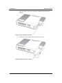
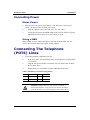
B-FOCuS O-4F2P Optical Network Termination (ONT) Installation and Configuration Manual 417006-2305-0H3-A04 B-FOCuS O-4F2P Installation and Configuration Manual August 2010 © Copyright by ECI Telecom, 2010. All rights reserved worldwide. This is a legal agreement between you, the end user, and ECI Telecom Ltd. (“ECI Telecom”). BY OPENING THE DOCUMENTATION AND/OR DISK PACKAGE, YOU ARE AGREEING TO BE BOUND BY THE TERMS OF THIS AGREEMENT. IF YOU DO NOT AGREE TO THE TERMS OF THIS AGREEMENT, PROMPTLY RETURN THE UNOPENED DOCUMENTATION AND/OR DISK PACKAGE AND THE ACCOMPANYING ITEMS (INCLUDING WRITTEN MATERIALS AND BINDERS OR OTHER CONTAINERS), TO THE PLACE FROM WHICH YOU OBTAINED THEM. The information contained in the documentation and/or disk is proprietary and is subject to all relevant copyright, patent, and other laws protecting intellectual property, as well as any specific agreement protecting ECI Telecom's rights in the aforesaid information. Neither this document nor the information contained in the documentation and/or disk may be published, reproduced, or disclosed to third parties, in whole or in part, without the express prior written permission of ECI Telecom. In addition, any use of this document, the documentation and/or the disk, or the information contained therein for any purposes other than those for which it was disclosed, is strictly forbidden. ECI Telecom reserves the right, without prior notice or liability, to make changes in equipment design or specifications. Information supplied by ECI Telecom is believed to be accurate and reliable. However, no responsibility whatsoever is assumed by ECI Telecom for the use thereof, nor for the rights of third parties, which may be affected in any way by the use and/or dissemination thereof. Any representation(s) in the documentation and/or disk concerning performance of ECI Telecom product(s) are for informational purposes only and are not warranties of product performance or otherwise, either express or implied. ECI Telecom's standard limited warranty, stated in its sales contract or order confirmation form, is the only warranty offered by ECI Telecom. The documentation and/or disk is provided “AS IS” and may contain flaws, omissions, or typesetting errors. No warranty is granted nor liability assumed in relation thereto, unless specifically undertaken in ECI Telecom's sales contract or order confirmation. Information contained in the documentation and in the disk is periodically updated, and changes will be incorporated in subsequent editions. If you have encountered an error, please notify ECI Telecom. All specifications are subject to change without prior notice. The documentation and/or disk and all information contained therein is owned by ECI Telecom and is protected by all relevant copyright, patent, and other applicable laws and international treaty provisions. Therefore, you must treat the information contained in the documentation and disk as any other copyrighted material (for example, a book or musical recording). Other Restrictions. You may not rent, lease, sell, or otherwise dispose of the documentation and disk, as applicable. YOU MAY NOT USE, COPY, MODIFY, OR TRANSFER THE DOCUMENTATION AND/OR DISK OR ANY COPY IN WHOLE OR PART, EXCEPT AS EXPRESSLY PROVIDED IN THIS LICENSE. ALL RIGHTS NOT EXPRESSLY GRANTED ARE RESERVED BY ECI TELECOM. All trademarks mentioned herein are the property of their respective holders. ECI Telecom shall not be liable to you or to any other party for any loss or damage whatsoever or howsoever caused, arising directly or indirectly in connection with this documentation and/or disk, the information contained therein, its use, or otherwise. Notwithstanding the generality of the aforementioned, you expressly waive any claim and/or demand regarding liability for indirect, special, incidental, or consequential loss or damage which may arise in respect of the documentation and/or disk and/or the information contained therein, howsoever caused, even if advised of the possibility of such damages. The end user hereby undertakes and acknowledges that they read the "Before You Start/Safety Guidelines" instructions and that such instructions were understood by them. It is hereby clarified that ECI Telecom shall not be liable to you or to any other party for any loss or damage whatsoever or howsoever caused, arising directly or indirectly in connection with you fulfilling and/or failed to fulfill in whole or in part the "Before You Start/Safety Guidelines" instructions. Contents About This Manual ........................................................................ vii Purpose .............................................................................................................. vii Intended Audience ............................................................................................. vii Overview ............................................................................................................ vii Document Conventions ..................................................................................... viii Obtaining Technical Documentation ................................................................... ix Technical Assistance............................................................................................x Product Description ................................................................ 1-1 Introduction....................................................................................................... 1-1 Services............................................................................................................ 1-2 Features ........................................................................................................... 1-2 Specifications ................................................................................................... 1-3 Safety ........................................................................................ 2-1 Electrical Safety ................................................................................................ 2-2 Laser Safety ..................................................................................................... 2-2 Installation................................................................................ 3-1 Get to Know the ONT ....................................................................................... 3-1 Site Preparation................................................................................................ 3-3 Wall or Table-Top Mounting ............................................................................. 3-4 Connecting to Network ..................................................................................... 3-5 Connecting The Telephone (POTS) Lines ....................................................... 3-7 Connecting Ethernet Lines ............................................................................... 3-8 Verify the Installation ........................................................................................ 3-8 Layer 3 Configuration ............................................................. 4-1 Status ............................................................................................................... 4-3 Network Configuration ...................................................................................... 4-5 Advanced Operations ....................................................................................... 4-9 Maintenance Operations ................................................................................ 4-13 Troubleshooting ...................................................................... 5-1 B-FOCuS O-4F2P Status LEDs ....................................................................... 5-1 Troubleshooting Procedures ............................................................................ 5-3 ECI Telecom Ltd. Proprietary i Contents ii B-FOCuS O-4F2P ECI Telecom Ltd. Proprietary List of Figures Figure 1: B-FOCuS O-4F2P ........................................................................................... 1-1 Figure 2: B-FOCuS O-4F2P product bottom label ......................................................... 2-1 Figure 3: ONT Top View ................................................................................................ 3-1 Figure 4: ONT Connector View ...................................................................................... 3-2 Figure 5: BBU Connector ............................................................................................... 3-2 Figure 6: ONT Mounting................................................................................................. 3-4 Figure 7: Remove the Laser Lock Door ......................................................................... 3-5 Figure 8: Plug in the fiber connector .............................................................................. 3-6 Figure 9: Attach the Laser Lock Door ............................................................................ 3-6 Figure 10: B-FOCuS O-4F2P has not yet been provisioned ......................................... 3-9 Figure 11: B-FOCuS O-4F2P has already been provisioned ........................................ 3-9 Figure 12: B-FOCuS O-4F2P Status LEDs location ...................................................... 5-1 ECI Telecom Ltd. Proprietary iii List of Tables Table 1: Physical specification ....................................................................................... 1-3 Table 2: Electrical specification ...................................................................................... 1-3 Table 3: Environmental specification ............................................................................. 1-3 Table 4: Compliance ...................................................................................................... 1-3 Table 5: Optical specification ......................................................................................... 1-4 Table 6: BBU Connector Pinout ..................................................................................... 3-2 Table 7: POTS RJ-11 connector wiring pattern ............................................................. 3-7 Table 8: Ethernet RJ-45 connector wiring pattern ......................................................... 3-8 Table 9: B-FOCuS O-4F2P Status LEDs description .................................................... 5-2 Table 10: Troubleshoot procedures ............................................................................... 5-3 ECI Telecom Ltd. Proprietary v About This Manual Purpose This guide describes how to install ECI’s Optical Network Termination (ONT) unit, B-FOCuS O-4F2P, at the customer premises. Intended Audience This document is intended for technicians responsible for: | Unpacking and mounting the ONT and power supply | Connecting the ONT to the PON network | Connecting external equipment to the ONT All ONT configurations are performed via the Element Management system with no configuration needed Overview This manual is organized as follows: | Chapter 1: Product Description Provides an introduction to the ONT including physical, electrical, environmental and optical specifications. | Chapter 2: Safety Provides electrical, electrostatic, and laser safety information; fiber optic cable handling techniques are also discussed. | Chapter 3: Installing the ONT Describes installation procedures including site preparation, unpacking and mounting the ONT, connecting power and fiber optic and cables, ECI Telecom Ltd. Proprietary vii About This Manual B-FOCuS O-4F2P connecting service cables, activating the ONT, and verifying the installation. | Chapter 4: Layer 3 Configuration Describes the procedures required to configure the system for layer 3 configuration. It details the GUI menu screens and lists the required parameters to be configured and options available | Chapter 5: Troubleshooting Explains ONT LED behavior and provides basic troubleshooting guidelines. Document Conventions If and where applicable, this manual uses the following conventions. Convention Indicates Example Italics New terms and emphasized Examples in text text Borders around text Notes, cautions, warnings, laser warnings, EDS warnings, tips, and important notes See examples below NOTE: Text set off in this manner presents clarifying information, specific instructions, commentary, sidelights, or interesting points of information. CAUTION: Text set off in this manner indicates that failure to follow directions could result in damage to equipment or loss of information. WARNING: Text set off in this manner indicates that failure to follow directions could result in bodily harm or loss of life. viii ECI Telecom Ltd. Proprietary B-FOCuS O-4F2P About This Manual LASER WARNING: Text set off in this manner indicates how to avoid personal injury. All personnel involved in equipment installation, operation, and maintenance must be aware that laser radiation is invisible. Therefore, although protective devices generally prevent direct exposure to the beam, personnel must strictly observe the applicable safety precautions and, in particular, must avoid staring into optical connectors, either directly or using optical instruments. ESD: Text set off in this manner indicates information on how to avoid discharge of static electricity and subsequent damage to the unit. TIP: Text set off in this manner includes helpful information and handy hints that can make your task easier. IMPORTANT: Text set off in this manner presents essential information you must pay attention to. Obtaining Technical Documentation To obtain technical documentation related to ECI Telecom products, please contact: ECI Telecom Ltd. Documentation Department 30 Hasivim St. Petach Tikva 49130 Israel Fax: +972-3-9268060 Email: [email protected] ECI Telecom Ltd. Proprietary ix About This Manual B-FOCuS O-4F2P Technical Assistance The configuration, installation, and operation of ECI Telecom products in a network are highly specialized processes. Due to the different nature of each installation, some planning aspects may not be covered in this manual. If you have questions or concerns about your network design or if you require installation personnel to perform the actual installation process, ECI Telecom maintains a staff of design engineers and highly trained field service personnel. The services of this group are available to customers at any time. If you are interested in obtaining design assistance or a network installation plan from ECI Telecom's Customer Support team, contact your ECI Telecom sales representative. With any support related issues, technical or logistic, please contact the ECI Telecom Customer Support center at your location. If you are not familiar with that location, please contact our central customer support center action line at: x Telephone +972-3-9266000 Telefax +972-3-9266370 Email [email protected] ECI Telecom Ltd. Proprietary 1 Product Description Introduction The B-FOCuS model O-4F2P Optical Network Terminal is an ITU-T G.984 compliant device that receives voice, data, and video traffic in the form of optical signal from the service provider’s passive optical network (PON) and transmitted it to the desired format at residential or business premises. Upstream traffic is likewise transmitted to the PON network via the fiber optic cable. A single optical fiber carries both upstream and downstream traffic. Figure 1: B-FOCuS O-4F2P ECI Telecom Ltd. Proprietary 1-1 Product Description B-FOCuS O-4F2P Services Equipped with ITU-T G.984 compliant 2.5Gbps Downlink and 1.25Gbps Uplink GPON interfaces, ONT O-4F2P supports the full Triple Play of services including voice, video (IPTV/VOD), and high speed internet access. B-FOCuS O-4F2P is equipped with the following service interfaces: | Four 10/100/1000 Base-T Ethernet ports for high speed internet access and IPTV/VOD services | Two POTS (VoIP) service ports for voice services ONT O-4F2P has built-in capability for remote management like supervision, monitoring, and maintenance. Note that two software version exist for this unit: | Bridge only: All four LAN ports act as bridge connections. | Home Gateway: Ports 1 and 2 are connected to a routed network connection, and ports 3 and 4 are bridge connections. Features The ONT incorporates the following features: 1 | Single fiber GPON interface with 1244Mbit/s upstream and 2488Mbit/s downstream data rates | Advanced data features such as VLAN tag manipulation, classification, and filtering. | Traffic classification and QoS capability | Analog Telephone Adapter (ATA) function integrated based on SIP (RFC3261), with various CLASS services supported - Caller ID, Call Waiting, Call Forwarding, Call Transfer, etc. 1 | 5 REN per line | Multiple voice Codec | Rich set of LED indications for alarming and maintenance These services may be unavailable within a specific carrier network and may require additional subscription. 1-2 ECI Telecom Ltd. Proprietary B-FOCuS O-4F2P Product Description Specifications The ONT’s physical, electrical, optical, and environmental specifications and compliance information are listed in the following tables. Table 1: Physical specification Dimensions 130mm (height) by 172mm (width) by 33mm (depth) Weight 0.4 KG excluding power adaptor GPON interface SC/APC angled optical connector POTS interface RJ-11 connector Ethernet interface RJ-45 connector Table 2: Electrical specification Input Power +12V DC power input Power Supply AC power supply with included power adapter Power Consumption Standard Table 3: Environmental specification Temperature -5 ~ 45° C Humidity 5 ~ 95% relative humidity Table 4: Compliance PON ITU-T G.984.1, G.984.2, G.984.2 amd1, G.984.3, G.984.4, G.983.2 EMC ETSI EN 300386, EN 55022 (Class B) Safety EN 60950 | Laser | | | ITU-T Rec.G.984.2 (Class B+), G983.3 FCC 47 CFR Part 15, Class B FDA 21 CFR 1040.10 and 1040.11, Class I IEC 60825, Class I ECI Telecom Ltd. Proprietary 1-3 Product Description B-FOCuS O-4F2P Table 5: Optical specification Minimum Nominal Maximum Wavelength 1260 nm 1310 nm 1360 nm Transmit power 0.5 dBm Notes Transmitter +5 dBm Digital receiver Wavelength 1480 nm Sensitivity -27 dBm Overload 1-4 1490 nm 1500 nm Minimum received power for BER<10-10 -8 dBm ECI Telecom Ltd. Proprietary Maximum received power for BER<10-10 2 Safety CAUTION: Product installation should be performed only by trained service personnel. Read and follow all warning notices and instructions marked on the product or included in its packaging, and observe all safety instructions listed in this guide while handling any ONT. Figure 2: B-FOCuS O-4F2P product bottom label ECI Telecom Ltd. Proprietary 2-1 Safety B-FOCuS O-4F2P Electrical Safety | Always use caution when handling live electrical connections. | Do not install electrical equipment in wet or damp conditions. | Ensure that the power source for the system is adequately rated to assure safe operation and provides current overload protection. | Do not allow anything to rest on the power cable, and do not place this product where people will stand or walk on the power cable. | To avoid electric shock of user which caused by over-voltage from PSTN, DO NOT connect the POTS port on this unit directly to external PSTN line. | This unit can only be used with the certified adaptor model included inside the package, which complies with the requirement of limited power source. WARNING: Do not open the enclosure without ECI’s permission and technical support, which is dangerous and voids the warranty. Laser Safety CAUTION: Use of controls or adjustments, or performance of procedures other than those specified herein may result in hazardous laser radiation exposure. Invisible laser radiation may be emitted from the ends of unterminated fiber cables or connectors. Never look directly into an un-terminated cable or connector. This ONT uses a class I laser device. WARNING: Personnel handling fiber optic cables must be trained for laser safety. CAUTION: Do not bend the fiber optic cable to a diameter smaller than 7.5 cm/3 inches. Doing so may damage the fiber or prevent the signal from passing through properly. 2-2 ECI Telecom Ltd. Proprietary 3 Installation Get to Know the ONT Look through the diagram below for getting an overview of several parts of the ONT. Laser Lock Door Figure 3: ONT Top View ECI Telecom Ltd. Proprietary 3-1 Installation B-FOCuS O-4F2P Power Connector Figure 4: ONT Connector View Two power connector types are available: The barrel (power) connector (as shown in Figure 4) is for use with the standard DC power adaptor. An 8-pin molex connector which can be connected either to a standard DC connector (supplied with the unit) or to a Battery Backup Unit (BBU a.k.a. UPS) The following defines the pin numbering of the 8-Pin Power BBU molex connector. Figure 5: BBU Connector Table 6: BBU Connector Pinout 3-2 Pin Pin Name Alarm Number 1 Power: Power Input (+12V) - 2 UPS Status: On Battery 1 3 UPS Status: Battery Missing 2 4 Signal Return - 5 Power: 12V Battery Return - 6 UPS Status: Replace Battery 3 7 UPS Status: Low Battery 4 8 NC Unused - ECI Telecom Ltd. Proprietary B-FOCuS O-4F2P Installation Site Preparation Environmental Requirements The ONT ambient temperature should not exceed 45° C and a relative humidity ranging from 5% to 95%. Installation Location The ONT should be located within 2 meters of the closest electrical point and within reach of the fiber termination point. Installation Options (application dependent) With BBU (Battery Backup Unit) or Ready for BBU When installed with a BBU or in preparation for a BBU to be added to the installation, the ONT must be installed on a wall with the connector side face down such that the cables leave the unit from the lower side. Wall installation is recommended for all applications. No BBU If no BBU is used, the ONT could also be installed flat on a desk or on the underside of a table. However, for this type of installation, special care must be taken to ensure that the ONT is fixed in place and that the fiber is protected. This is not the recommended installation procedure. Power Requirements The ONT is shipped with a universal power adaptor. However, before installation, check if the AC power input matches the specification printed on the power adaptor (input voltage, current, etc.) CAUTION: Please use the power adaptor within the package only, or the replacement unit that provided by ECI. Other power adaptor may cause damage to the ONT. ECI Telecom Ltd. Proprietary 3-3 Installation B-FOCuS O-4F2P Wall or Table-Top Mounting Wall Installation - Recommended The ONT must be installed with the cables leaving the ONT in the downward direction. The placement of the ONT should leave at least 8 cm of free space below the ONT for cables to exit with an adequate bend radius. Two centimeters should be left free on all sides of the unit to allow ventilation. 11 cm Figure 6: ONT Mounting On the wall, draw a horizontal line 3 cm from the top of where the ONT is to be placed. On the line that you have drawn, mark two holes as shown in Figure 6 showing how the ONT is to be mounted and drill 2 holes for 3.5 x30 mm screws. Fix the two mounting screw in place and slide the ONT onto the mounting screws until it is locked in place. 3-4 ECI Telecom Ltd. Proprietary B-FOCuS O-4F2P Installation Connecting to Network 1. Remove the screw and pull the Laser Lock Door in up to down direction, Push the corner of Laser Lock Door to 15 degree and pull at the same time. Figure 7: Remove the Laser Lock Door NOTE: If necessary, hold the unit steady while opening and closing the Laser Lock Door. 2. Remove the Laser Lock Door 3. Remove the dust covers from the SC/APC optical connectors. Clean the connector if necessary. ECI Telecom Ltd. Proprietary 3-5 Installation B-FOCuS O-4F2P 4. Plug in the fiber connector to connect the B-FOCuS O-4F2P to the network. Figure 8: Plug in the fiber connector 5. Attach the Laser Lock Door to the B-FOCuS O-4F2P. Figure 9: Attach the Laser Lock Door 3-6 ECI Telecom Ltd. Proprietary B-FOCuS O-4F2P Installation Connecting Power Mains Power 1. Plug the circle two pin (or 8-pin Molex ) 12V DC power connector of power converter to ONT O-4F2P power port 2. Plug the input of power converter into a live AC outlet 3. Verify that the power (POWER) LED on the ONT O-4F2P is lit green indicating that local power is on and voltage is good. Using a BBU When a BBU is used, connect the Molex connector from the BBU into the Power connector instead of the regular AC/DC adaptor. Connecting The Telephone (POTS) Lines 1. Locate the premises’ telephone wire pair. 2. If the wire pair is not terminated, follow local practices to attach an RJ11 connector. 3. Plug the wire pair with RJ-11 connector into one of the ONT O-4F2P RJ-11 phone jacks. 4. Repeat steps 2-3 as needed to connect additional phone lines. Table 7: POTS RJ-11 connector wiring pattern Pin Signal Pin Signal 1 Unused 3 Tip 2 Ring 4 Unused WARNING: Please make sure the wire pair connected is from/to the telephone. Using the wire pair from/to the PSTN network incorrectly may cause damage to user and the device. ECI Telecom Ltd. Proprietary 3-7 Installation B-FOCuS O-4F2P Connecting Ethernet Lines 1. Locate the premises’ Ethernet LAN cable. 2. If the cable is not terminated, follow local practices to attach an RJ-45 connector. Table shows Ethernet RJ-45 connector wiring information. 3. Plug the Ethernet cable into the B-FOCuS O-4F2P RJ-45 Ethernet port. 4. Repeat step 2-3 as needed to connect additional Ethernet cables. Table 8: Ethernet RJ-45 connector wiring pattern Pin Color Signal Pin Color Signal 1 Orange/White Tx + 5 Blue/White Unused 2 Orange Tx — 6 Green Rx — 3 Green/White Rx + 7 Brown/White Unused 4 Blue Unused 8 Brown Unused Verify the Installation Check LED states to verify ONT O-4F2P status. Services are not available until the ONT is ranged and provisioned in the PON network. The B-FOCuS O-4F2P is activated and configured through the E-OPS Element Manager. Refer to the E-OPS Hi-Care User Guide for details. Verifying B-FOCuS O-4F2P Status Once the B-FOCuS O-4F2P installation is complete, follow the procedure below for verifying B-FOCuS O-4F2P status. The figures below show the typical status LED display after the B-FOCuS O-4F2P boot sequence is complete. 3-8 ECI Telecom Ltd. Proprietary B-FOCuS O-4F2P Installation Figure 10: B-FOCuS O-4F2P has not yet been provisioned Figure 11: B-FOCuS O-4F2P has already been provisioned 1. Verify that the POWER LED lights green indicating that local power level is good. 2. Verify that the OPTICAL LED lights green indicating that the B-FOCuS O4F2P is operating normally. If the B-FOCuS O-4F2P has already been provisioned in the network, the OPTICAL LED lights green after the B-FOCuS O-4F2P boot sequence and PON ranging process is complete (approximately 1 minute after power up). During that ranging process, the OPTICAL LED flashes continually. The B-FOCuS O-4F2P is placed into service remotely through the OLT. Services to the B-FOCuS O-4F2P are likewise provisioned and turned up remotely through the PON network. 3. If the OPTICAL LED lights green, indicating that the B-FOCuS O-4F2P is communicating with the PON network, no further activation is necessary and you can proceed to Section Verifying Services. 4. If the OPTICAL LED does not light green, contact the NOC (Network Operation Center) to activate the line. You may be required to provide or confirm the following information about the B-FOCuS O-4F2P: vendor, model number, serial number. Once the B-FOCuS O-4F2P has been activated in the network, and the OPTICAL LED lights green, you can proceed to Section Verifying Services. ECI Telecom Ltd. Proprietary 3-9 Installation B-FOCuS O-4F2P Verifying Services Follow local practices to connect to each active service port in the B-FOCuS O4F2P to confirm service activation. 1. Connect to each active phone jack to verify telephone numbers and services. Verify that the POTS LED lights green when a line is off hook. 2. If Ethernet service is included in this installation, confirm that data is being received and transmitted normally. The LAN LED flashes during data transmission. Configuration of the B-FOCuS O-4F2P As mentioned above, the B-FOCuS O-4F2P is activated and configured through the E-OPS Element Manager. Refer to the E-OPS Hi-Care User Guide for details. No local management interface in the B-FOCuS O-4F2P is required unless L3 services are enabled or if password activation is used. The Layer 3 service (PPPoE/DHCP/NAT) is available through Ethernet port 1 or 2only. Layer 3 configuration is detailed in the chapter that follows. 3-10 ECI Telecom Ltd. Proprietary 4 Layer 3 Configuration This section describes the procedures required to configure the B-FOCuS O-4F2P Optical Network Terminal (ONT) system for layer 3 configuration. It details the GUI menu screens and lists the required parameters to be configured and options available. Logging In To log into the B-FOCuS’s GUI menu screens: 1. Connect the PC LAN connection to one of the Layer 3 UNI connections (Ethernet port 1 or 2). 2. Enter the device’s default gateway IP address as the URL in the Internet Web browser. 3. Log in to the GUI menu screens. ECI Telecom Ltd. Proprietary 4-1 Layer 3 Configuration B-FOCuS O-4F2P Default user name: root Default password: admin The default user name and password can be changed, as described in the Maintenance section below. Note: If the user name /password have been changed and are not known, you can reset the system and revert to the default user name /password values by pressing the Reset button for more than 5 seconds. Be aware that this will also reset all other configured values to the factory defaults. 4-2 ECI Telecom Ltd. Proprietary B-FOCuS O-4F2P Layer 3 Configuration Status The Status screens allow you to view the status details of the B-FOCuS ONT device and of the WAN connection. All values in these status screens are read only. Device Info The Status > Device Info screen is the initial screen shown when accessing the GUI. It presents information about the B-FOCuS ONT device. The following details are shown: • Equipment ID • Hardware Version • Software Version • Build date (Year-Month-Day) • Device Unique MAC Address • Current Time (date and system clock) ECI Telecom Ltd. Proprietary 4-3 Layer 3 Configuration B-FOCuS O-4F2P WAN Status The Status > WAN Status screen shows status details of the WAN connection. Note: These parameters are defined by the user in the Network > WAN screen, as detailed below. The following details are shown: 4-4 • Internet Connection Type (PPPoE, DHCP, or Static IP) • Connection status • IP Address • Subnet Mask • Default gateway • DNS Server 1 • DNS Server 2 ECI Telecom Ltd. Proprietary B-FOCuS O-4F2P Layer 3 Configuration Network Configuration Network configuration consists of defining the LAN and the WAN connection parameters. LAN Configuration The LAN configuration parameters can be configured. The following parameters are shown/can be configured: • MAC Address of the internal DHCP server is shown • Local IP Address of the internal DHCP server can be changed • Subnet Mask of the internal DHCP server is shown • Internal DHCP Server: Enable or Disable If Enable is selected, all the following parameters are enabled and can be edited. If Disable is selected, the following parameters are disabled. • DHCP Server - Starting IP Address • DHCP Server - Max Number of DHCP Users (valid values: 1-254) • DHCP Server - Client Lease Time (in minutes) (The value 0 means 3 days.) • DHCP Server - IP Address Range (as defined by the starting IP address and maximum number of users) is shown • Option60 Class ID1 ECI Telecom Ltd. Proprietary 4-5 Layer 3 Configuration B-FOCuS O-4F2P • Option60 Class ID1 - Starting IP Address • Option60 Class ID1 - Max Number of Option60 Users • Option60 Class ID2 • Option60 Class ID2 - Starting IP Address • Option60 Class ID2 - Max Number of Option60 Users WAN Configuration The WAN configuration parameters can be configured. There are three Internet connection types available – the ways to get the WAN IP address: PPPoE, DHCP, or Static IP. The screen will refresh with the appropriate parameters depending on the Internet connection type selected. Select the Internet Connection Type - PPPoE, DHCP, or Static IP PPPoE WAN Configuration: PPPoE internal dialer should be selected and configured when the client serviced by a High Speed Internet Provider uses a PPPoE/BRAS server. The following details are shown and can be configured: 4-6 • Connection status: Connected / Disconnected to the provider’s server • IP Address is obtain automatically from the provider when the PPPoE connection is up • Subnet Mask is supplied by the provider ECI Telecom Ltd. Proprietary B-FOCuS O-4F2P Layer 3 Configuration • Default gateway is supplied by the provider • DNS Server 1 is supplied by the provider • DNS Server 2 is supplied by the provider (optional) • User Name and Password (for PPPoE dialup, unique) is supplied by the provider • Connection Mode: select Keep Alive or Manual • Redial Period (in seconds) can be entered (valid values: 5-25) DHCP WAN Configuration: DHCP internal client should be selected and configured when the client serviced by a High Speed Internet Provider uses a DHCP server with dynamic IP Addresses distribution. If DHCP is selected, you can click to connect or disconnect the DHCP connection. The following details are shown: • Connection status: Connected / Disconnected to the provider’s server • Internal MAC Address of the DHCP client • IP Address is obtained automatically from the provider • Subnet Mask is supplied by the provider • Default gateway is supplied by the provider • DNS Server 1 is supplied by the provider • DNS Server 2 is supplied by the provider (optionally) ECI Telecom Ltd. Proprietary 4-7 Layer 3 Configuration B-FOCuS O-4F2P Static IP WAN Configuration: Static IP should be selected and configured when the client serviced by a High Speed Internet Provider uses a DHCP server with unique Static IP Address distribution. If Static IP is selected, the following details can be entered: 4-8 • A unique IP Address is supplied by the provider and should be entered by the customer • Subnet Mask is supplied by the provider and should be entered by the customer • Default gateway is supplied by the provider and should be entered by the customer • DNS Server 1 is supplied by the provider and should be entered by the customer • DNS Server 2 is supplied by provider (optionally) ECI Telecom Ltd. Proprietary B-FOCuS O-4F2P Layer 3 Configuration Advanced Operations The Advanced screens allow you to configure a few advanced features – SNTP, DDNS, port forwarding, and the firewall. SNTP Configuration The SNTP configuration parameters can be configured. Select to Enable or Disable the SNTP State. If the SNTP State is enabled, the screen refreshes and the following details can be entered: • SNTP Time Server – select one of the NTP time servers listed in the drop-down menu, or select Other and manually enter an address is the available field below it. • Time Zone – select a time zone (GMT +/-) from the drop-down list If the selected NTP time server is reachable, the system time will be synchronized according to the selected time zone. ECI Telecom Ltd. Proprietary 4-9 Layer 3 Configuration B-FOCuS O-4F2P DDNS Service The DDNS configuration parameters can be configured. Select the DDNS Service from the drop-down list (None, DynDNS.org, or TZO.com). The screen will refresh with the appropriate parameters that can be configured. If DynDNS.org is selected, the following details can be entered: • User Name • Password • Host Name If TZO.com is selected, the following details can be entered: 4-10 • Email Address • Tzo Password • Domain Name ECI Telecom Ltd. Proprietary B-FOCuS O-4F2P Layer 3 Configuration Port Forwarding Port forwarding rules can be configured. For each port forwarding operation required, enter the following parameters: • Application name • Start and end ports (valid values: 0-65535) • Protocol – select TCP, UDP or Both from the drop-down list • To IP Address • Start and end ports (valid values: 0-65535) • Check to enable ECI Telecom Ltd. Proprietary 4-11 Layer 3 Configuration B-FOCuS O-4F2P Firewall The firewall configuration parameters can be configured (Web access can be enabled/disabled) and you can make an internal host work as the DMZ host. The following parameters can be configured: 4-12 • Web Access from LAN – select Enable or Disable • Web Access from WAN – select Enable or Disable • DMZ – select Enable or Disable • DMZ Host – enter the IP address • UPnP Enable – select Enable or Disable ECI Telecom Ltd. Proprietary B-FOCuS O-4F2P Layer 3 Configuration Maintenance Operations The Maintenance screens allow you to configure a few maintenance features: • Changing the password • Restore to factory default • Reboot the device • Upgrade the firmware Change Password The default user name/password is root/admin. The password should be changed if security is required. In the Maintain > Password screen, enter, and re-enter to confirm, the new password. ECI Telecom Ltd. Proprietary 4-13 Layer 3 Configuration B-FOCuS O-4F2P Reset Factory Default You can reset the system configuration, including all configured values (as well as the defined user name and password) to their default factory values by clicking Reset in the Maintenance > Factory Default screen. Note: In addition to using this screen, the system configuration can be reset to the factory default values by pressing the Reset button on the back of the B-FOCuS for more than 5 seconds. Be aware that resetting to the factory default will reset all configured values and cannot be undone! Reboot Device You can reboot the system if needed by clicking Reboot in the Maintenance > Reboot Device screen. 4-14 ECI Telecom Ltd. Proprietary B-FOCuS O-4F2P Layer 3 Configuration Upgrade Firmware If a firmware upgrade is needed, you can select the firmware file to be uploaded in the Maintenance > Upgrade screen. The new firmware file (software image), supplied by the system vendor, should be saved on the local PC. To upgrade the firmware, click Browse to select the firmware file stored on the local PC, and click Upgrade. The firmware will automatically be uploaded to the device and installed. ECI Telecom Ltd. Proprietary 4-15 Layer 3 Configuration 4-16 B-FOCuS O-4F2P ECI Telecom Ltd. Proprietary 5 Troubleshooting B-FOCuS O-4F2P Status LEDs The B-FOCuS O-4F2P status LEDs located on the enclosure (Figure 12) assist with installation and maintenance procedures. These LEDs are described in detail in Table 9. Figure 12: B-FOCuS O-4F2P Status LEDs location ECI Telecom Ltd. Proprietary 5-1 Troubleshooting B-FOCuS O-4F2P Table 9: B-FOCuS O-4F2P Status LEDs description LED Name POWER OPTICAL Color Indicates Green/Solid B-FOCuS O-4F2P operating from AC power. Green/Flash System Booting. Red/Solid Optical interface abnormal (LOS/LOF). Green/Solid B-FOCuS O-4F2P working normally. Green/Flash B-FOCuS O-4F2P in ranging and synchronization process. Bridge At least one of the Ethernet links is up. PPPoE/DHCP signup completed successfully. Internet is now connected. Green/Flash At least one of the Ethernet links is up and there is activity of receiving and transmitting data. L2 path is completed and now is proceeding with PPPoE/DHCP signup. OFF No Ethernet link is up or the B-FOCuS O-4F2P is not ready for running Ethernet service. No service is configured or provisioned. Green/Flash The device in upgrading process, but the data traffic is not affected. Red/Solid Upgrade failure. OFF B-FOCuS O-4F2P working normally. Green/Solid No alarm with local access enabled Red/Flash Software out of order. Red/Solid Hardware out of order. OFF No alarm. Green/Solid At least one POTS interfaces is in off-hook condition. Green/Flash At least one POTS interfaces is in off-hook condition for at least one hour. OFF All POTS interfaces are in the on-hook condition or the BFOCuS O-4F2P is not ready for running POTS service. Green/Solid LAN UPDATE ALARM POTS 5-2 Gateway ECI Telecom Ltd. Proprietary B-FOCuS O-4F2P Troubleshooting Troubleshooting Procedures Table 10: Troubleshoot procedures Problem Possible Solutions Make sure the power cable connector is properly seated in the B-FOCuS O-4F2P power input. Verify that the power adapter is plugged into a live AC outlet. Check the power cable for shorts or breaks. The POWER LED is off Check the status of the POWER Button. If it is lit in red, push and release the button to turn on the power. Disconnect the power input connector at the B-FOCuS O4F2P and use a voltmeter to verify that the proper voltage level is present on the 12 V pin (power and power return) from the power adapter. Power cycle the B-FOCuS O-4F2P by unplugging it from The ALARM LED is red the power adapter, then plugging it back in. If the Bflashed or in red solid FOCuS O-4F2P fails the self test a second time, replace the unit. Check the optical path. The OPTICAL LED is in Reset the B-FOCuS O-4F2P by reset button. If the Bred solid FOCuS O-4F2P fails again, replace the unit. The OPTICAL LED is always green flashed This is normal at boot-up and may take up to 1 minute to turn green. If this state persists, contact the NOC (Network Operation Center) to verify that the B-FOCuS O-4F2P serial number, password, and vendor ID match those provisioned in the network database. If provisioning is correct, have the NOC determine whether there are alarms on the PON feeding the BFOCuS O-4F2P. If no alarms exist, use an optical power meter to troubleshoot the fiber network. The UPDATE LED is in red solid Contact NOC. The POTS LED is off Check the telephone connection, or voice service is when telephone off-hook disabled. Contact NOC for verification. ECI Telecom Ltd. Proprietary 5-3 Troubleshooting 5-4 B-FOCuS O-4F2P ECI Telecom Ltd. Proprietary